

#clmel
Understanding MPLS
BRKMPL - 1101
Khurram WaheedSystems Engineer
© 2015 Cisco and/or its affi liates. All rights reserved.BRKMPL-1101 Cisco Public
Session Goals
• Understand the problems MPLS is addressing
• Understand major MPLS technology components
• Understand typical MPLS applications
• Understand benefits of deploying MPLS
© 2015 Cisco and/or its affi liates. All rights reserved.BRKMPL-1101 Cisco Public
Agenda
• Introduction
• MPLS Basics
• MPLS Layer-3 VPNs
• MPLS Layer-2 VPNs
• MPLS Traffic Engineering
• Summary

Introduction
© 2015 Cisco and/or its affi liates. All rights reserved.BRKMPL-1101 Cisco Public
Why Multi-Protocol Label Switching?
• SP/Carrier perspective
– Reduce costs (CAPEX/OPEX); consolidate networks and maximise utilisation of resources.
– Consolidated network for multiple Layer-2/3 services over same infrastructure
– Support increasingly stringent SLAs (Voice + Video etc.)
• Enterprise/end-user perspective
– Campus/LAN
– Need for network segmentation (users, applications, etc.)
© 2015 Cisco and/or its affi liates. All rights reserved.BRKMPL-1101 Cisco Public
What is MPLS?
• It’s all about labels …
• Use the best of both worlds– Layer-2: efficient forwarding and traffic engineering
– Layer-3: flexible and scalable
• MPLS forwarding plane– Use of labels for forwarding Layer-2/3 data traffic
– Labeled packets are switched; instead of routed• Leverage layer-2 forwarding efficiency
• MPLS control/signalling plane– Use of existing IP control protocols extensions + new protocols
to exchange label information• Leverage layer-3 control protocol flexibility and scalability
Brief Summary

MPLS Basics
© 2015 Cisco and/or its affi liates. All rights reserved.BRKMPL-1101 Cisco Public
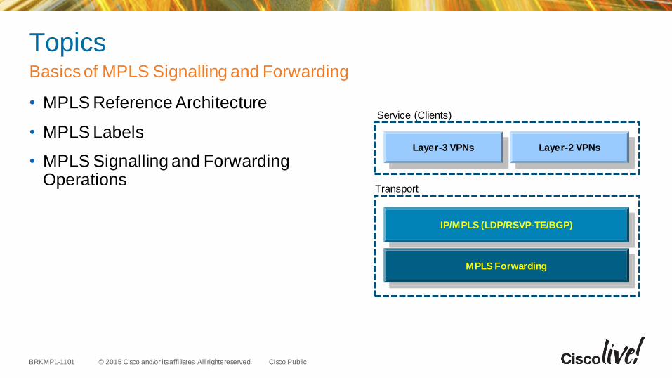
Topics
• MPLS Reference Architecture
• MPLS Labels
• MPLS Signalling and Forwarding Operations
Basics of MPLS Signalling and Forwarding
Transport
MPLS Forwarding
IP/MPLS (LDP/RSVP-TE/BGP)
Layer-3 VPNs Layer-2 VPNs
Service (Clients)
© 2015 Cisco and/or its affi liates. All rights reserved.BRKMPL-1101 Cisco Public
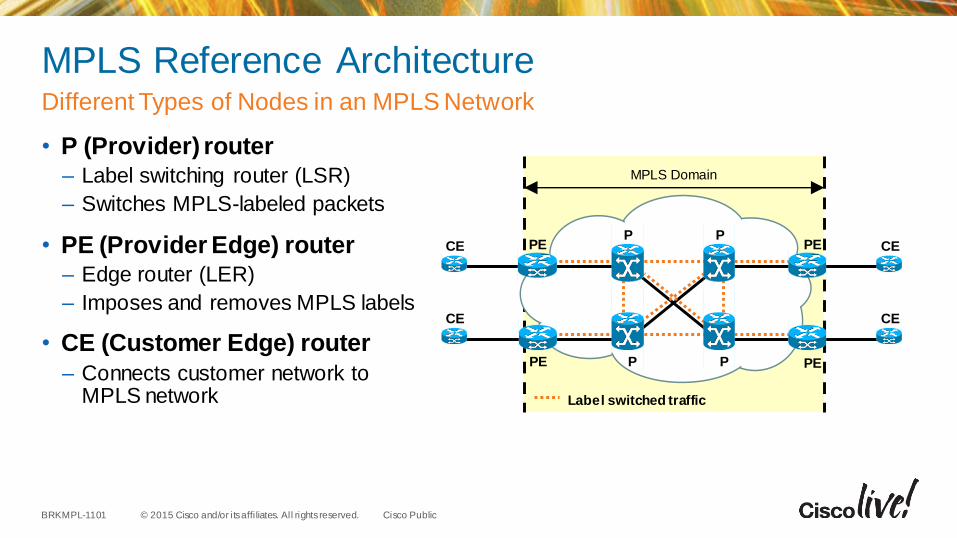
MPLS Reference Architecture
• P (Provider) router – Label switching router (LSR)
– Switches MPLS-labeled packets
• PE (Provider Edge) router– Edge router (LER)
– Imposes and removes MPLS labels
• CE (Customer Edge) router
– Connects customer network to MPLS network
Different Types of Nodes in an MPLS Network
MPLS Domain
CE
CE
CE
CE
Label switched traffic
P
P
P
P
PE
PE PE
PE
© 2015 Cisco and/or its affi liates. All rights reserved.BRKMPL-1101 Cisco Public
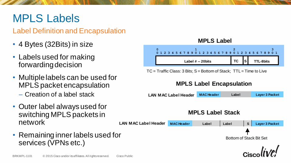
MPLS Labels
• 4 Bytes (32Bits) in size
• Labels used for making forwarding decision
• Multiple labels can be used for MPLS packet encapsulation
– Creation of a label stack
• Outer label always used for switching MPLS packets in network
• Remaining inner labels used for services (VPNs etc.)
Label Definition and Encapsulation
TC = Traffic Class: 3 Bits; S = Bottom of Stack; TTL = Time to Live
0 1 2 30 1 2 3 4 5 6 7 8 9 0 1 2 3 4 5 6 7 8 9 0 1 2 3 4 5 6 7 8 9 0 1
Label # – 20bits TC S TTL-8bits
MPLS Label
MPLS Label Encapsulation
LAN MAC Label Header LabelMAC Header Layer 3 Packet
MPLS Label Stack
LAN MAC Label Header LabelMAC Header Layer 3 PacketLabel S
Bottom of Stack Bit Set
© 2015 Cisco and/or its affi liates. All rights reserved.BRKMPL-1101 Cisco Public
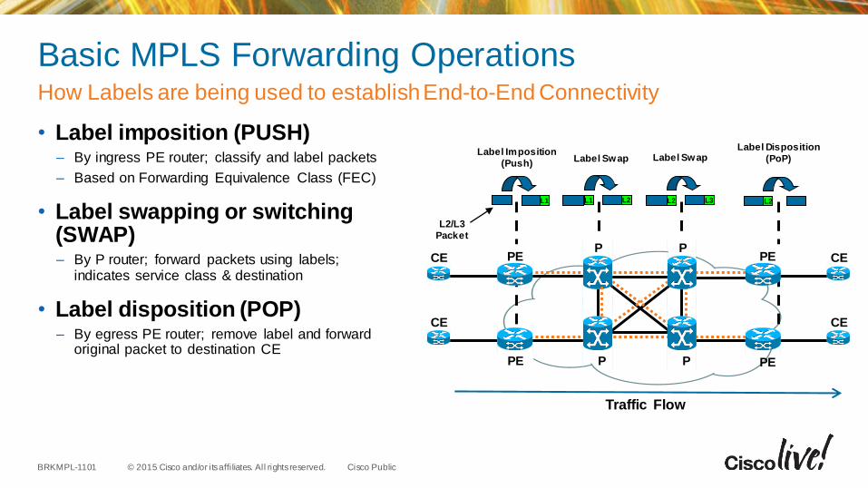
Basic MPLS Forwarding Operations
• Label imposition (PUSH)– By ingress PE router; classify and label packets
– Based on Forwarding Equivalence Class (FEC)
• Label swapping or switching (SWAP)– By P router; forward packets using labels;
indicates service class & destination
• Label disposition (POP)– By egress PE router; remove label and forward
original packet to destination CE
How Labels are being used to establish End-to-End Connectivity
CE
CE
CE
CE
PE
PE
PE
L1
Label Imposition
(Push)
L2/L3
Packet
Label Swap Label Swap
PE
Label Disposition
(PoP)
P
P
P
P
L2L1 L3L2 L2
Traffic Flow
© 2015 Cisco and/or its affi liates. All rights reserved.BRKMPL-1101 Cisco Public
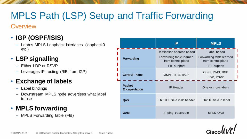
MPLS Path (LSP) Setup and Traffic Forwarding
• IGP (OSPF/ISIS)– Learns MPLS Loopback Interfaces (loopback0
etc.)
• LSP signalling– Either LDP or RSVP
– Leverages IP routing (RIB from IGP)
• Exchange of labels– Label bindings
– Downstream MPLS node advertises what label to use
• MPLS forwarding– MPLS Forwarding table (FIB)
Overview
IP MPLS
Forwarding
Destination address based
Forwarding table learned
from control plane
TTL support
Label based
Forwarding table learned
from control plane
TTL support
Control Plane OSPF, IS-IS, BGPOSPF, IS-IS, BGP
LDP, RSVP
Packet
EncapsulationIP Header One or more labels
QoS 8 bit TOS field in IP header 3 bit TC field in label
OAM IP ping, traceroute MPLS OAM
© 2015 Cisco and/or its affi liates. All rights reserved.BRKMPL-1101 Cisco Public
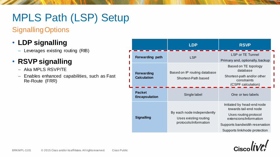
MPLS Path (LSP) Setup
• LDP signalling– Leverages existing routing (RIB)
• RSVP signalling– Aka MPLS RSVP/TE
– Enables enhanced capabilities, such as Fast Re-Route (FRR)
SignallingOptions
LDP RSVP
Forwarding path LSPLSP or TE Tunnel
Primary and, optionally, backup
Forwarding
Calculation
Based on IP routing database
Shortest-Path based
Based on TE topology
database
Shortest-path and/or other constraints
(CSPF calculation)
Packet
EncapsulationSingle label One or two labels
Signalling
By each node independently
Uses existing routing
protocols/information
Initiated by head-end node
towards tail-end node
Uses routing protocolextensions/information
Supports bandwidth reservation
Supports link/node protection
© 2015 Cisco and/or its affi liates. All rights reserved.BRKMPL-1101 Cisco Public
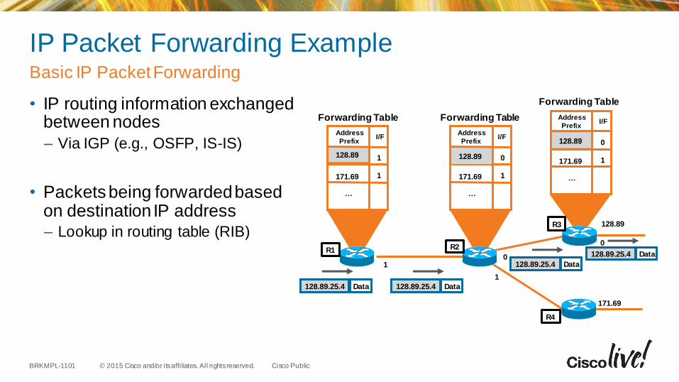
IP Packet Forwarding Example
• IP routing information exchanged between nodes
– Via IGP (e.g., OSFP, IS-IS)
• Packets being forwarded based on destination IP address– Lookup in routing table (RIB)
Basic IP Packet Forwarding
0
1
1
128.89
171.69
0
128.89.25.4 Data
128.89.25.4 Data
128.89.25.4 Data
…
128.89
171.69
Address
PrefixI/F
1
1
…
128.89
171.69
Address
PrefixI/F
0
1 …
128.89
171.69
Address
PrefixI/F
0
1
Forwarding Table Forwarding Table
Forwarding Table
128.89.25.4 DataR1 R2
R3
R4
© 2015 Cisco and/or its affi liates. All rights reserved.BRKMPL-1101 Cisco Public
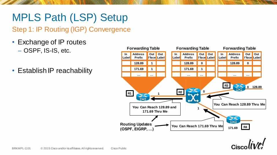
MPLS Path (LSP) Setup
• Exchange of IP routes– OSPF, IS-IS, etc.
• Establish IP reachability
Step 1: IP Routing (IGP) Convergence
128.89
171.69
01
In
Label
Address
Prefix
…
Out
I’face
128.89 1
171.69 1
…
Out
Label
In
Label
Address
Prefix
…
Out
I’face
128.89 0
171.69 1
…
Out
Label
In
Label
Address
Prefix
128.89
…
Out
I’face
0
…
Out
Label
0
You Can Reach 171.69 Thru Me
You Can Reach 128.89 and
171.69 Thru Me
Routing Updates
(OSPF, EIGRP, …)
You Can Reach 128.89 Thru Me
Forwarding Table Forwarding Table Forwarding Table
1
R1 R2
R3
R4
© 2015 Cisco and/or its affi liates. All rights reserved.BRKMPL-1101 Cisco Public
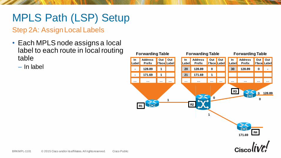
MPLS Path (LSP) Setup
• Each MPLS node assigns a local label to each route in local routing table– In label
Step 2A: Assign Local Labels
1
128.89
01
0
171.69
In
Label
Address
Prefix
128.89
171.69
…
Out
I’face
1
1
…
Out
Label
In
Label
Address
Prefix
128.89
171.69
…
Out
I’face
0
1
…
Out
Label
In
Label
Address
Prefix
128.89
…
Out
I’face
0
…
Out
Label
…
-
-
… …
20
21
…
-
…
30
…
Forwarding Table Forwarding Table Forwarding Table
0
R1 R2
R3
R4
© 2015 Cisco and/or its affi liates. All rights reserved.BRKMPL-1101 Cisco Public
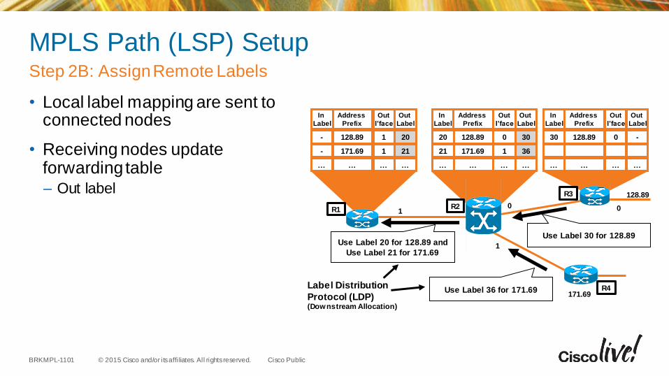
MPLS Path (LSP) Setup
• Local label mapping are sent to connected nodes
• Receiving nodes update forwarding table– Out label
Step 2B: Assign Remote Labels
1
128.89
01
Use Label 30 for 128.89Use Label 20 for 128.89 and
Use Label 21 for 171.69
Label Distribution
Protocol (LDP)(Downstream Allocation)
171.69Use Label 36 for 171.69
In
Label
Address
Prefix
128.89
171.69
…
Out
I’face
1
1
…
Out
Label
In
Label
Address
Prefix
128.89
171.69
…
Out
I’face
0
1
…
Out
Label
In
Label
Address
Prefix
128.89
…
Out
I’face
0
…
Out
Label
20
21
…
-
-
…
30
36
…
20
21
…
-
…
30
…
0R1 R2
R3
R4
© 2015 Cisco and/or its affi liates. All rights reserved.BRKMPL-1101 Cisco Public
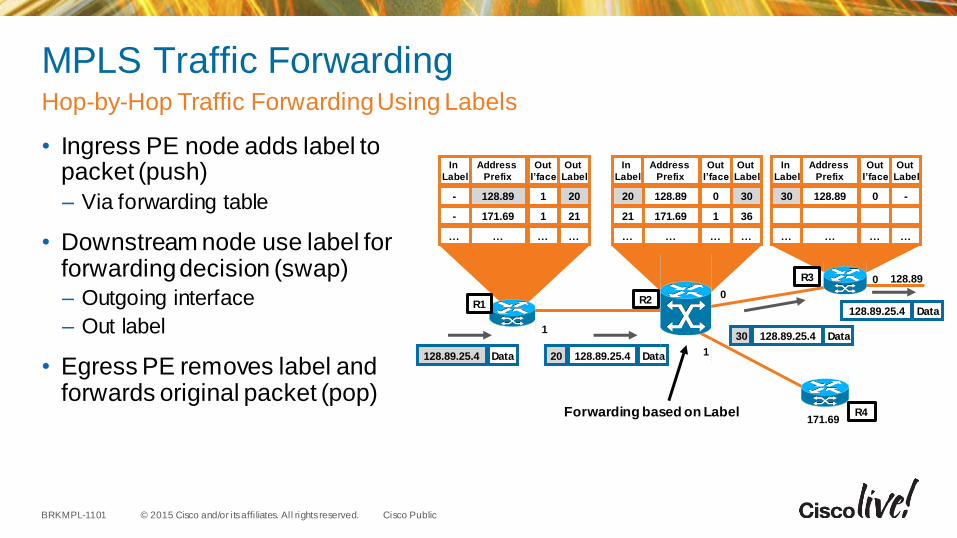
MPLS Traffic Forwarding
• Ingress PE node adds label to packet (push)
– Via forwarding table
• Downstream node use label for forwarding decision (swap)– Outgoing interface
– Out label
• Egress PE removes label and forwards original packet (pop)
Hop-by-Hop Traffic Forwarding Using Labels
1
0
128.89.25.4 Data 128.89.25.4 Data20
128.89.25.4 Data30
Forwarding based on Label
128.89.25.4 Data
128.890
171.69
In
Label
Address
Prefix
128.89
171.69
…
Out
I’face
1
1
…
Out
Label
In
Label
Address
Prefix
128.89
171.69
…
Out
I’face
0
1
…
Out
Label
In
Label
Address
Prefix
128.89
…
Out
I’face
0
…
Out
Label
20
21
…
-
-
…
30
36
…
20
21
…
-
…
30
…
1
R1 R2
R3
R4
© 2015 Cisco and/or its affi liates. All rights reserved.BRKMPL-1101 Cisco Public
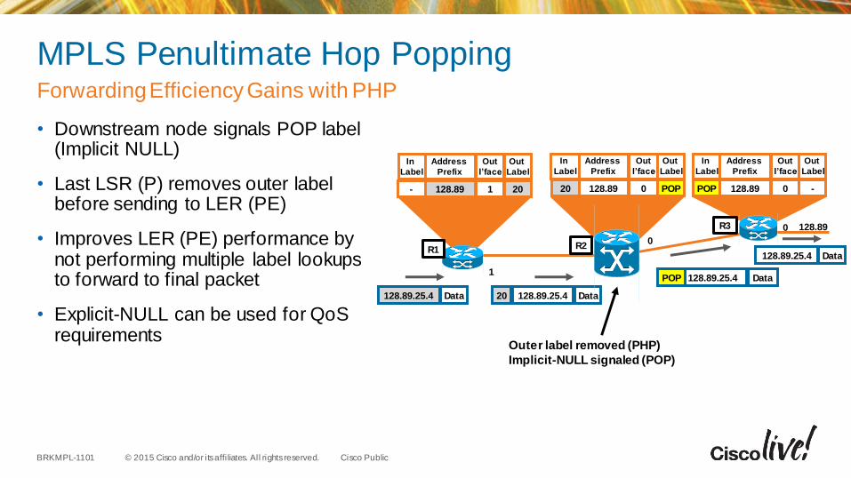
MPLS Penultimate Hop Popping
• Downstream node signals POP label (Implicit NULL)
• Last LSR (P) removes outer label before sending to LER (PE)
• Improves LER (PE) performance by not performing multiple label lookups to forward to final packet
• Explicit-NULL can be used for QoSrequirements
Forwarding Efficiency Gains with PHP
0
128.89.25.4 Data 128.89.25.4 Data20
128.89.25.4 DataPOP
Outer label removed (PHP)
Implicit-NULL signaled (POP)
128.89.25.4 Data
128.890
In
Label
Address
Prefix
128.89
Out
I’face
1
Out
Label
In
Label
Address
Prefix
128.89
Out
I’face
0
Out
Label
In
Label
Address
Prefix
128.89
Out
I’face
0
Out
Label
20- POP20 -POP
1
R1 R2
R3
© 2015 Cisco and/or its affi liates. All rights reserved.BRKMPL-1101 Cisco Public
Summary…So Far...
• MPLS networks consist of PE routers at in/egress and P routers in core
• Traffic is encapsulated with label(s) at ingress (PE router)
• Labels are removed at egress (PE router)
• MPLS forwarding operations include label imposition (PUSH), swapping (SWAP), and disposition (POP)
• Penultimate Hop Popping (PHP) is used to improve LER performance.
• LDP and/or RSVP can be used for signalling label mapping information to set up an end-to-end Label Switched Path (LSP)
Key Takeaways

MPLS Virtual Private Networks
© 2015 Cisco and/or its affi liates. All rights reserved.BRKMPL-1101 Cisco Public
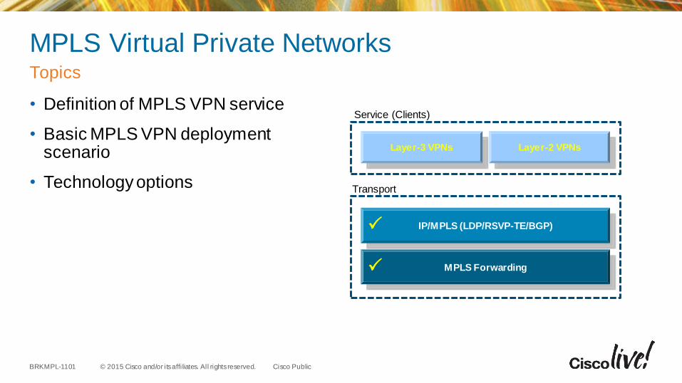
MPLS Virtual Private Networks
• Definition of MPLS VPN service
• Basic MPLS VPN deployment scenario
• Technology options
Topics
Transport
MPLS Forwarding
IP/MPLS (LDP/RSVP-TE/BGP)
Layer-3 VPNs Layer-2 VPNs
Service (Clients)
© 2015 Cisco and/or its affi liates. All rights reserved.BRKMPL-1101 Cisco Public
What is a Virtual Private Network?
• Set of sites which communicate with each other– Typically over a shared public or private network infrastructure
• Defined by a set of administrative policies– Policies established by VPN customers themselves (DIY)
– Policies implemented by VPN service provider (managed/unmanaged)
• Different inter-site connectivity schemes possible
– Full mesh, partial mesh, hub-and-spoke, etc.
• VPN sites may be either within the same or in different organisations
– VPN can be either intranet (same org) or extranet (multiple orgs)
Definition
© 2015 Cisco and/or its affi liates. All rights reserved.BRKMPL-1101 Cisco Public
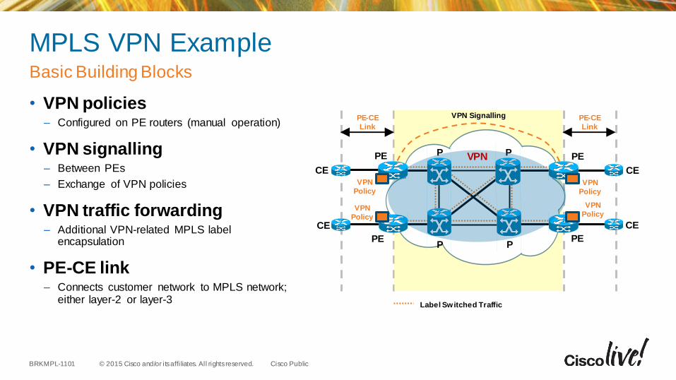
MPLS VPN Example
• VPN policies– Configured on PE routers (manual operation)
• VPN signalling– Between PEs
– Exchange of VPN policies
• VPN traffic forwarding– Additional VPN-related MPLS label
encapsulation
• PE-CE link– Connects customer network to MPLS network;
either layer-2 or layer-3
Basic Building Blocks
Label Switched Traffic
P
P
PE
PE
CE
PE-CE
Link
PE-CE
Link
P
P
CE
PE
PE
CE
CEVPN
Policy
VPN
Policy
VPN
Policy
VPN
Policy
VPN Signalling
VPN
© 2015 Cisco and/or its affi liates. All rights reserved.BRKMPL-1101 Cisco Public
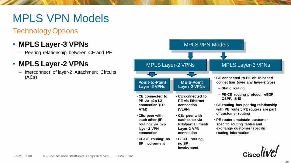
MPLS VPN Models
• MPLS Layer-3 VPNs– Peering relationship between CE and PE
• MPLS Layer-2 VPNs– Interconnect of layer-2 Attachment Circuits
(ACs)
Technology Options
26
MPLS VPN Models
• CE connected to PE via IP-based
connection (over any layer-2 type)
– Static routing
– PE-CE routing protocol; eBGP, OSPF, IS-IS
• CE routing has peering relationship
with PE router; PE routers are part of customer routing
• PE routers maintain customer-
specific routing tables and exchange customer=specific
routing information
MPLS Layer-3 VPNsMPLS Layer-2 VPNs
Point-to-PointLayer-2 VPNs
Multi-PointLayer-2 VPNs
• CE connected to
PE via p2p L2connection (FR,
ATM)
• CEs peer with each other (IP
routing) via p2p
layer-2 VPNconnection
• CE-CE routing; no
SP involvement
• CE connected to
PE via Ethernet connection
(VLAN)
• CEs peer with each other via
fully/partial mesh
Layer-2 VPNconnection
• CE-CE routing;
no SP involvement
MPLS Layer-3 Virtual Private Networks
© 2015 Cisco and/or its affi liates. All rights reserved.BRKMPL-1101 Cisco Public
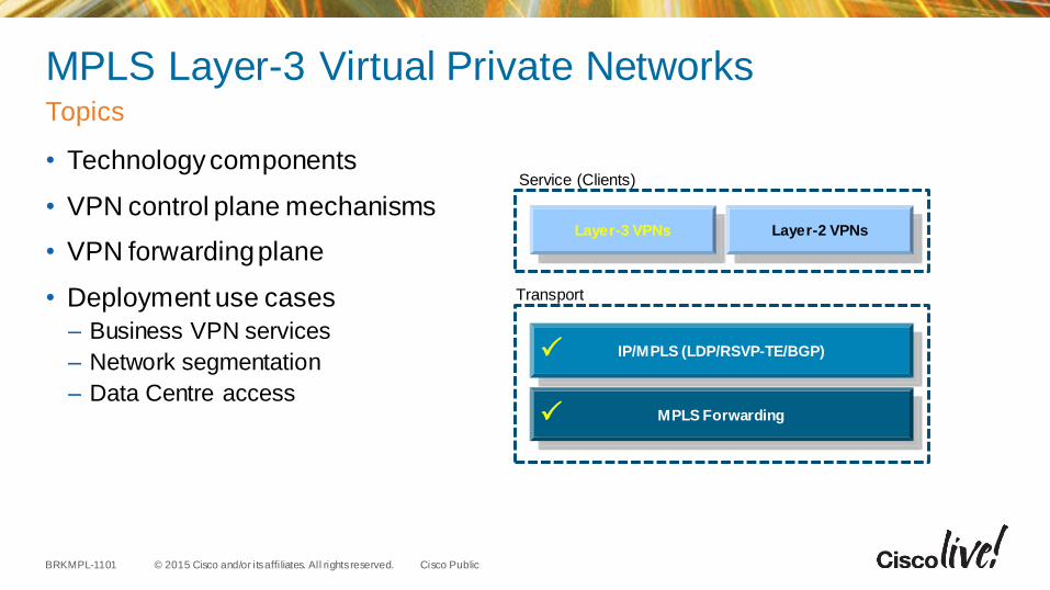
MPLS Layer-3 Virtual Private Networks
• Technology components
• VPN control plane mechanisms
• VPN forwarding plane
• Deployment use cases
– Business VPN services
– Network segmentation
– Data Centre access
Topics
Transport
MPLS Forwarding
IP/MPLS (LDP/RSVP-TE/BGP)
Layer-3 VPNs Layer-2 VPNs
Service (Clients)
© 2015 Cisco and/or its affi liates. All rights reserved.BRKMPL-1101 Cisco Public
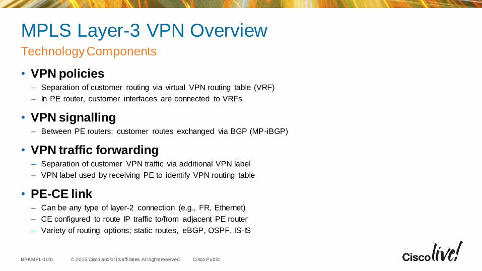
MPLS Layer-3 VPN Overview
• VPN policies– Separation of customer routing via virtual VPN routing table (VRF)
– In PE router, customer interfaces are connected to VRFs
• VPN signalling– Between PE routers: customer routes exchanged via BGP (MP-iBGP)
• VPN traffic forwarding– Separation of customer VPN traffic via additional VPN label
– VPN label used by receiving PE to identify VPN routing table
• PE-CE link– Can be any type of layer-2 connection (e.g., FR, Ethernet)
– CE configured to route IP traffic to/from adjacent PE router
– Variety of routing options; static routes, eBGP, OSPF, IS-IS
Technology Components
© 2015 Cisco and/or its affi liates. All rights reserved.BRKMPL-1101 Cisco Public
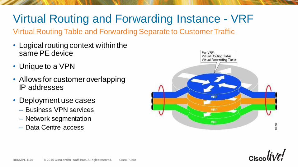
Virtual Routing and Forwarding Instance - VRF
• Logical routing context within the same PE device
• Unique to a VPN
• Allows for customer overlapping IP addresses
• Deployment use cases
– Business VPN services
– Network segmentation
– Data Centre access
Virtual Routing Table and Forwarding Separate to Customer Traffic
© 2015 Cisco and/or its affi liates. All rights reserved.BRKMPL-1101 Cisco Public
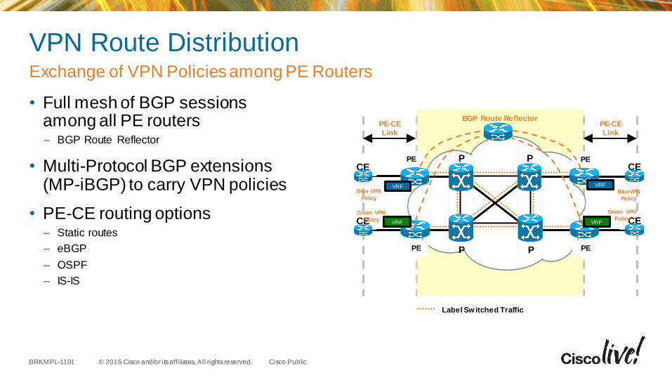
VPN Route Distribution
• Full mesh of BGP sessions among all PE routers– BGP Route Reflector
• Multi-Protocol BGP extensions (MP-iBGP) to carry VPN policies
• PE-CE routing options– Static routes
– eBGP
– OSPF
– IS-IS
Exchange of VPN Policies among PE Routers
Label Switched Traffic
P
P
PE
PE
CE
PE-CE
Link
PE-CE
Link
P
P
CEPE
PE
CE
CE
VRFBlue VPN
PolicyBlueVPN
Policy
VRF
Green VPN
Policy
Green VPN
Policy
BGP Route Reflector
VRF
VRF
© 2015 Cisco and/or its affi liates. All rights reserved.BRKMPL-1101 Cisco Public
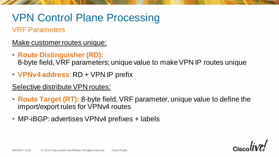
VPN Control Plane Processing
Make customer routes unique:
• Route Distinguisher (RD): 8-byte field, VRF parameters; unique value to make VPN IP routes unique
• VPNv4 address: RD + VPN IP prefix
Selective distribute VPN routes:
• Route Target (RT): 8-byte field, VRF parameter, unique value to define the import/export rules for VPNv4 routes
• MP-iBGP: advertises VPNv4 prefixes + labels
VRF Parameters
© 2015 Cisco and/or its affi liates. All rights reserved.BRKMPL-1101 Cisco Public
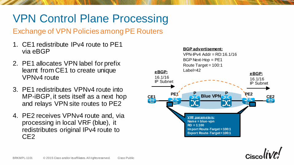
VPN Control Plane Processing
1. CE1 redistribute IPv4 route to PE1 via eBGP
2. PE1 allocates VPN label for prefix learnt from CE1 to create unique VPNv4 route
3. PE1 redistributes VPNv4 route into MP-iBGP, it sets itself as a next hop and relays VPN site routes to PE2
4. PE2 receives VPNv4 route and, via processing in local VRF (blue), it redistributes original IPv4 route to CE2
Exchange of VPN Policies among PE Routers
Blue VPN
BGP advertisement:
VPN-IPv4 Addr = RD:16.1/16
BGP Next-Hop = PE1
Route Target = 100:1
Label=42
PPE1
eBGP:
16.1/16 IP Subnet
PCE1
PE2CE2
eBGP:
16.1/16 IP Subnet
ip vrf blue-vpn
RD 1:100
route-target export 1:100
route-target import 1:100
VRF parameters:
Name = blue-vpn
RD = 1:100
Import Route-Target = 100:1
Export Route-Target = 100:1
© 2015 Cisco and/or its affi liates. All rights reserved.BRKMPL-1101 Cisco Public
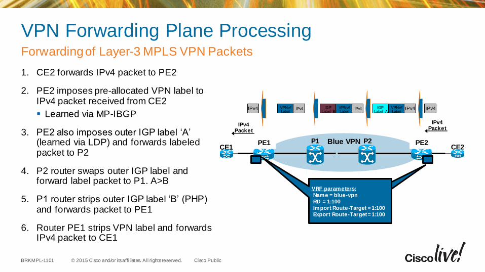
VPN Forwarding Plane Processing
1. CE2 forwards IPv4 packet to PE2
2. PE2 imposes pre-allocated VPN label to IPv4 packet received from CE2
Learned via MP-IBGP
3. PE2 also imposes outer IGP label ‘A’ (learned via LDP) and forwards labeled packet to P2
4. P2 router swaps outer IGP label and forward label packet to P1. A>B
5. P1 router strips outer IGP label ‘B’ (PHP) and forwards packet to PE1
6. Router PE1 strips VPN label and forwards IPv4 packet to CE1
Forwarding of Layer-3 MPLS VPN Packets
Blue VPNP1PE1 P2CE1
PE2CE2
ip vrf blue-vpn
RD 1:100
route-target export 1:100
route-target import 1:100
VRF parameters:
Name = blue-vpn
RD = 1:100
Import Route-Target = 1:100
Export Route-Target = 1:100
IPv4Packet
IPv4IPv4VPNv4Label
IGPLabel A
IPv4VPNv4Label
IGPLabel B
IPv4VPNv4Label
IPv4Packet
IPv4
© 2015 Cisco and/or its affi liates. All rights reserved.BRKMPL-1101 Cisco Public
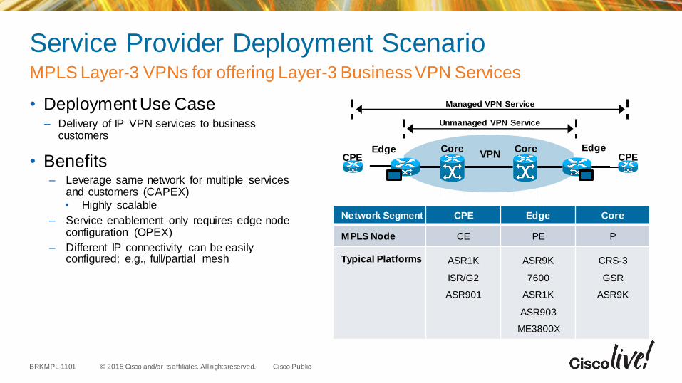
Service Provider Deployment Scenario
• Deployment Use Case– Delivery of IP VPN services to business
customers
• Benefits– Leverage same network for multiple services
and customers (CAPEX)
• Highly scalable
– Service enablement only requires edge node configuration (OPEX)
– Different IP connectivity can be easily configured; e.g., full/partial mesh
MPLS Layer-3 VPNs for offering Layer-3 Business VPN Services
VPNCoreEdge Core
CPEEdge
CPE
Managed VPN Service
Unmanaged VPN Service
Network Segment CPE Edge Core
MPLS Node CE PE P
Typical Platforms ASR1K
ISR/G2
ASR901
ASR9K
7600
ASR1K
ASR903
ME3800X
CRS-3
GSR
ASR9K
© 2015 Cisco and/or its affi liates. All rights reserved.BRKMPL-1101 Cisco Public
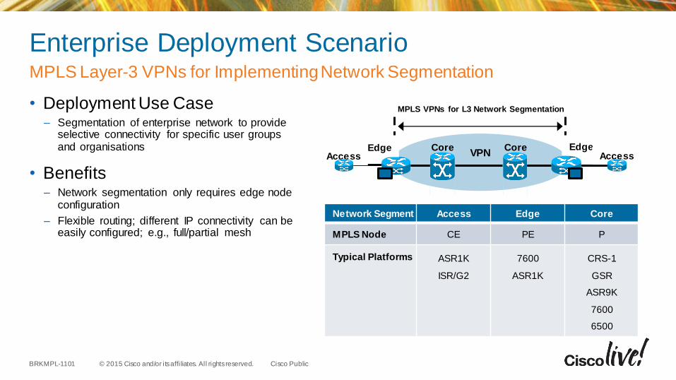
Enterprise Deployment Scenario
• Deployment Use Case– Segmentation of enterprise network to provide
selective connectivity for specific user groups and organisations
• Benefits– Network segmentation only requires edge node
configuration
– Flexible routing; different IP connectivity can be easily configured; e.g., full/partial mesh
MPLS Layer-3 VPNs for Implementing Network Segmentation
VPNCoreEdge Core
AccessEdge
Access
MPLS VPNs for L3 Network Segmentation
Network Segment Access Edge Core
MPLS Node CE PE P
Typical Platforms ASR1K
ISR/G2
7600
ASR1K
CRS-1
GSR
ASR9K
7600
6500
© 2015 Cisco and/or its affi liates. All rights reserved.BRKMPL-1101 Cisco Public
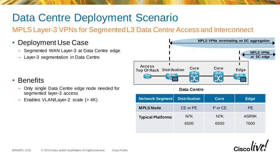
Data Centre Deployment Scenario
• Deployment Use Case– Segmented WAN Layer-3 at Data Centre edge
– Layer-3 segmentation in Data Centre
• Benefits– Only single Data Centre edge node needed for
segmented layer-3 access
– Enables VLAN/Layer-2 scale (> 4K)
MPLS Layer-3 VPNs for Segmented L3 Data Centre Access and Interconnect
CoreDistribution CoreAccess
Top Of Rack Edge
MPLS VPNs terminating on DC aggregation
Network Segment Distribution Core Edge
MPLS Node CE or PE P or CE PE
Typical Platforms N7K
6500
N7K
6500
ASR9K
7600
MPLS VPNs
at DC edge
Data Centre

MPLS Layer-2 Virtual Private Networks
© 2015 Cisco and/or its affi liates. All rights reserved.BRKMPL-1101 Cisco Public
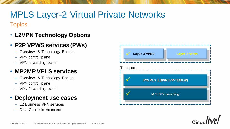
MPLS Layer-2 Virtual Private Networks
• L2VPN Technology Options
• P2P VPWS services (PWs)– Overview & Technology Basics
– VPN control plane
– VPN forwarding plane
• MP2MP VPLS services– Overview & Technology Basics
– VPN control plane
– VPN forwarding plane
• Deployment use cases– L2 Business VPN services
– Data Centre Interconnect
Topics
Transport
MPLS Forwarding
IP/MPLS (LDP/RSVP-TE/BGP)
Layer-3 VPNs Layer-2 VPNs
© 2015 Cisco and/or its affi liates. All rights reserved.BRKMPL-1101 Cisco Public
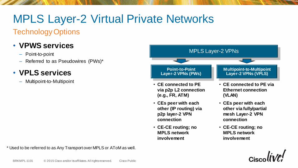
MPLS Layer-2 Virtual Private Networks
• VPWS services– Point-to-point
– Referred to as Pseudowires (PWs)*
• VPLS services– Multipoint-to-Multipoint
Technology Options
* Used to be referred to as Any Transport over MPLS or AToM as well.
MPLS Layer-2 VPNs
Point-to-PointLayer-2 VPNs (PWs)
Multipoint-to-MultipointLayer-2 VPNs (VPLS)
• CE connected to PE
via p2p L2 connection (e.g., FR, ATM)
• CEs peer with each
other (IP routing) via
p2p layer-2 VPN
connection
• CE-CE routing; no
MPLS network
involvement
• CE connected to PE via
Ethernet connection (VLAN)
• CEs peer with each
other via fully/partial
mesh Layer-2 VPN
connection
• CE-CE routing; no
MPLS network
involvement
© 2015 Cisco and/or its affi liates. All rights reserved.BRKMPL-1101 Cisco Public
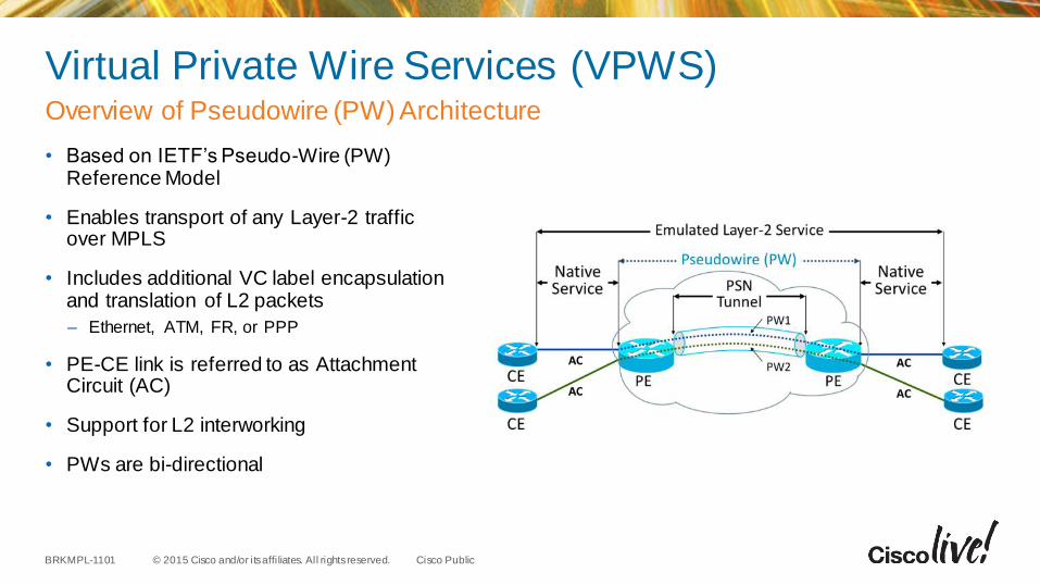
Virtual Private Wire Services (VPWS)
• Based on IETF’s Pseudo-Wire (PW) Reference Model
• Enables transport of any Layer-2 traffic over MPLS
• Includes additional VC label encapsulation and translation of L2 packets
– Ethernet, ATM, FR, or PPP
• PE-CE link is referred to as Attachment Circuit (AC)
• Support for L2 interworking
• PWs are bi-directional
Overview of Pseudowire (PW) Architecture
© 2015 Cisco and/or its affi liates. All rights reserved.BRKMPL-1101 Cisco Public
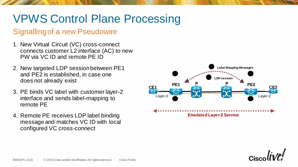
VPWS Control Plane Processing
1. New Virtual Circuit (VC) cross-connect connects customer L2 interface (AC) to new PW via VC ID and remote PE ID
2. New targeted LDP session between PE1 and PE2 is established, in case one does not already exist
3. PE binds VC label with customer layer-2 interface and sends label-mapping to remote PE
4. Remote PE receives LDP label binding message and matches VC ID with local configured VC cross-connect
Signallingof a new Pseudowire
2 LDP session
3 Label Mapping Messages
1 1
44
PPE1 PCE1
PE2CE2
Layer-2 Layer-2
Emulated Layer-2 Service
© 2015 Cisco and/or its affi liates. All rights reserved.BRKMPL-1101 Cisco Public
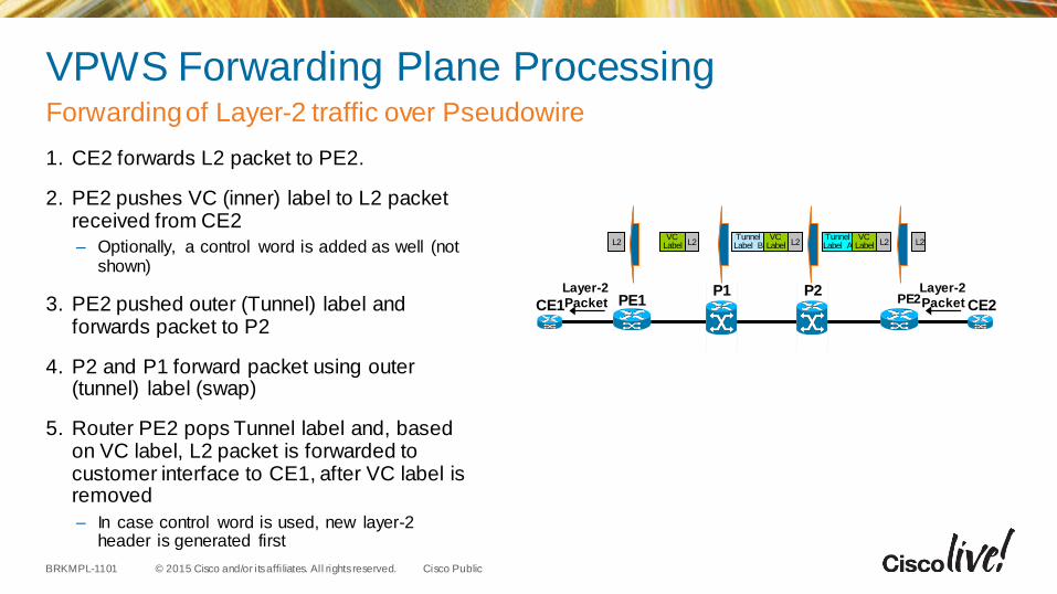
VPWS Forwarding Plane Processing
1. CE2 forwards L2 packet to PE2.
2. PE2 pushes VC (inner) label to L2 packet received from CE2
– Optionally, a control word is added as well (not shown)
3. PE2 pushed outer (Tunnel) label and forwards packet to P2
4. P2 and P1 forward packet using outer (tunnel) label (swap)
5. Router PE2 pops Tunnel label and, based on VC label, L2 packet is forwarded to customer interface to CE1, after VC label is removed
– In case control word is used, new layer-2 header is generated first
Forwarding of Layer-2 traffic over Pseudowire
P2P1PE1 PE2
CE1 CE2
Layer-2Packet
Layer-2Packet
L2L2VC
LabelTunnelLabel AL2
VCLabel
TunnelLabel BL2
VCLabelL2
© 2015 Cisco and/or its affi liates. All rights reserved.BRKMPL-1101 Cisco Public
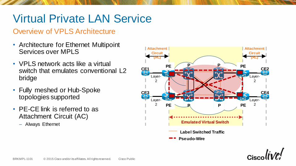
Virtual Private LAN Service
• Architecture for Ethernet Multipoint Services over MPLS
• VPLS network acts like a virtual switch that emulates conventional L2 bridge
• Fully meshed or Hub-Spoke topologies supported
• PE-CE link is referred to as Attachment Circuit (AC)– Always Ethernet
Overview of VPLS Architecture
Label Switched Traffic
P
P
PE
PE
CE3
Attachment
Circuit (AC)
Attachment
Circuit (AC)
P
P
CE1PE
PE
CE4
CE2
Pseudo-Wire
Emulated Virtual Switch
Layer-
2
Layer-
2
Layer-
2
Layer-
2
© 2015 Cisco and/or its affi liates. All rights reserved.BRKMPL-1101 Cisco Public
Virtual Private LAN Service (VPLS)
• VPN policies– Virtual Switching Instance or VSI
– One or more customer interfaces are connected to VSI
– One or more PWs for interconnection with related VSI instances on remote PE
• VPN signalling– Full mesh of targeted LDP* (VC exchange) and/or BGP sessions (discovery and VC exchange)
– Virtual Connection (VC)-label negotiation, withdrawal, error notification
• VPN traffic forwarding– 1 VC label used for encapsulation + 1 (IGP) label for forwarding
– Inner de-multiplexer (VC) label: identifies VSI
– Outer tunnel (IGP) label: to get from ingress to egress PE using MPLS LSP
• PE-CE link– Referred to as Attachment Circuit (AC)
– Ethernet VCs are either port mode or VLAN ID
Technology Components
© 2015 Cisco and/or its affi liates. All rights reserved.BRKMPL-1101 Cisco Public
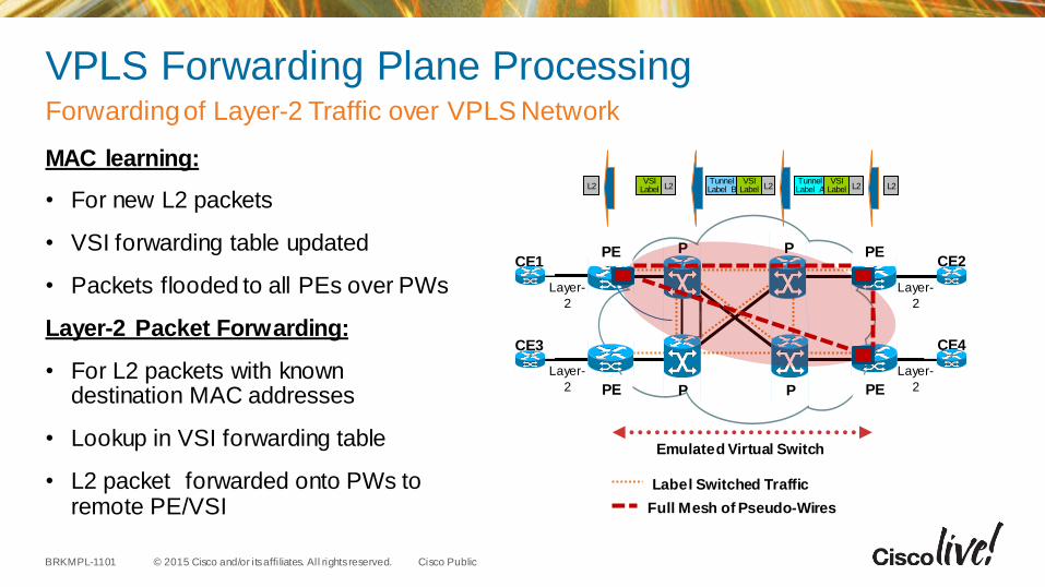
VPLS Forwarding Plane Processing
MAC learning:
• For new L2 packets
• VSI forwarding table updated
• Packets flooded to all PEs over PWs
Layer-2 Packet Forwarding:
• For L2 packets with known destination MAC addresses
• Lookup in VSI forwarding table
• L2 packet forwarded onto PWs to remote PE/VSI
Forwarding of Layer-2 Traffic over VPLS Network
Label Switched Traffic
P
P
PE
PE
CE3
P
P
CE1PE
PE
CE4
CE2
Full Mesh of Pseudo-Wires
Emulated Virtual Switch
Layer-
2
Layer-
2
Layer-
2
Layer-
2
L2L2VSI
LabelTunnelLabel AL2
VSILabel
TunnelLabel BL2
VSILabelL2
© 2015 Cisco and/or its affi liates. All rights reserved.BRKMPL-1101 Cisco Public
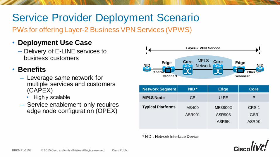
Service Provider Deployment Scenario
• Deployment Use Case– Delivery of E-LINE services to
business customers
• Benefits– Leverage same network for
multiple services and customers (CAPEX)• Highly scalable
– Service enablement only requires edge node configuration (OPEX)
PWs for offering Layer-2 Business VPN Services (VPWS)
Network Segment NID * Edge Core
MPLS Node CE U-PE P
Typical Platforms M3400
ASR901
ME3800X
ASR903
ASR9K
CRS-1
GSR
ASR9K
MPLS
NetworkCoreEdge Core
NIDEdge
NID
Layer-2 VPN Service
Ethernet
xconnect xconnect
Ethernet
* NID : Network Interface Device
© 2015 Cisco and/or its affi liates. All rights reserved.BRKMPL-1101 Cisco Public
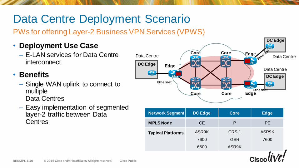
Data Centre Deployment Scenario
• Deployment Use Case– E-LAN services for Data Centre
interconnect
• Benefits
– Single WAN uplink to connect to multiple Data Centres
– Easy implementation of segmented layer-2 traffic between Data Centres
PWs for offering Layer-2 Business VPN Services (VPWS)
Network Segment DC Edge Core Edge
MPLS Node CE P PE
Typical Platforms ASR9K
7600
6500
CRS-1
GSR
ASR9K
ASR9K
7600
Core
Core
Edge
Core
Core
DC Edge
Edge
Edge
DC Edge
Ethernet
Data Centre Data Centre
DC Edge
Data Centre
Ethernet
© 2015 Cisco and/or its affi liates. All rights reserved.BRKMPL-1101 Cisco Public
Summary Layer 2 VPN
• L2VPNs enable transport of any Layer-2 traffic over MPLS network
• L2 packets encapsulated into additional VC label
• Both LDP and BGP can be used for L2VPN signalling
• PWs suited for implementing transparent point-to-point connectivity between Layer-2 circuits (E-LINE services)
• VPLS suited for implementing transparent point-to-multipoint connectivity between Ethernet links/sites (E-LAN services)
• Typical applications of L2VPNs are layer-2 business VPN services and Data Centre interconnect
Technology Components

MPLS Traffic Engineering
© 2015 Cisco and/or its affi liates. All rights reserved.BRKMPL-1101 Cisco Public
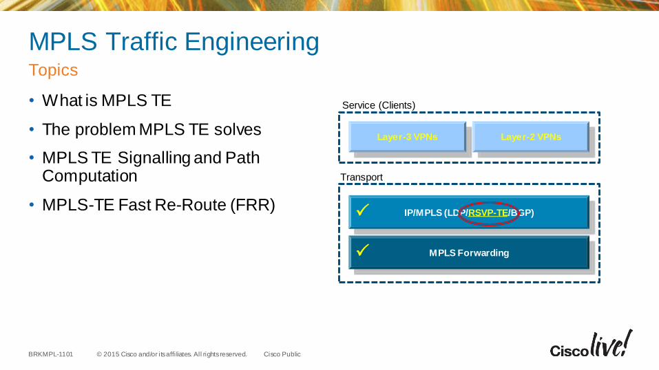
MPLS Traffic Engineering
• What is MPLS TE
• The problem MPLS TE solves
• MPLS TE Signalling and Path Computation
• MPLS-TE Fast Re-Route (FRR)
Topics
Transport
MPLS Forwarding
IP/MPLS (LDP/RSVP-TE/BGP)
Layer-3 VPNs Layer-2 VPNs
Service (Clients)
© 2015 Cisco and/or its affi liates. All rights reserved.BRKMPL-1101 Cisco Public
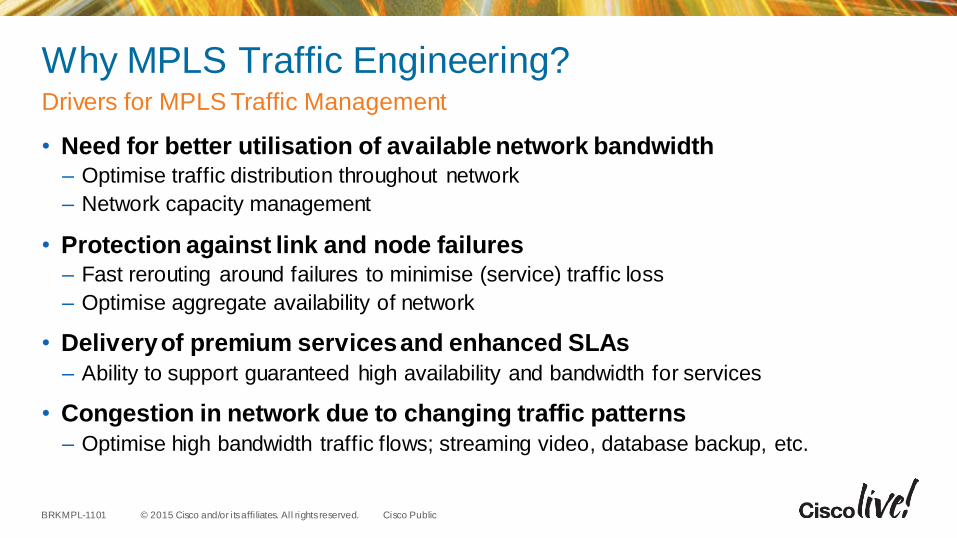
Why MPLS Traffic Engineering?
• Need for better utilisation of available network bandwidth– Optimise traffic distribution throughout network
– Network capacity management
• Protection against link and node failures– Fast rerouting around failures to minimise (service) traffic loss
– Optimise aggregate availability of network
• Delivery of premium services and enhanced SLAs
– Ability to support guaranteed high availability and bandwidth for services
• Congestion in network due to changing traffic patterns
– Optimise high bandwidth traffic flows; streaming video, database backup, etc.
Drivers for MPLS Traffic Management
© 2015 Cisco and/or its affi liates. All rights reserved.BRKMPL-1101 Cisco Public
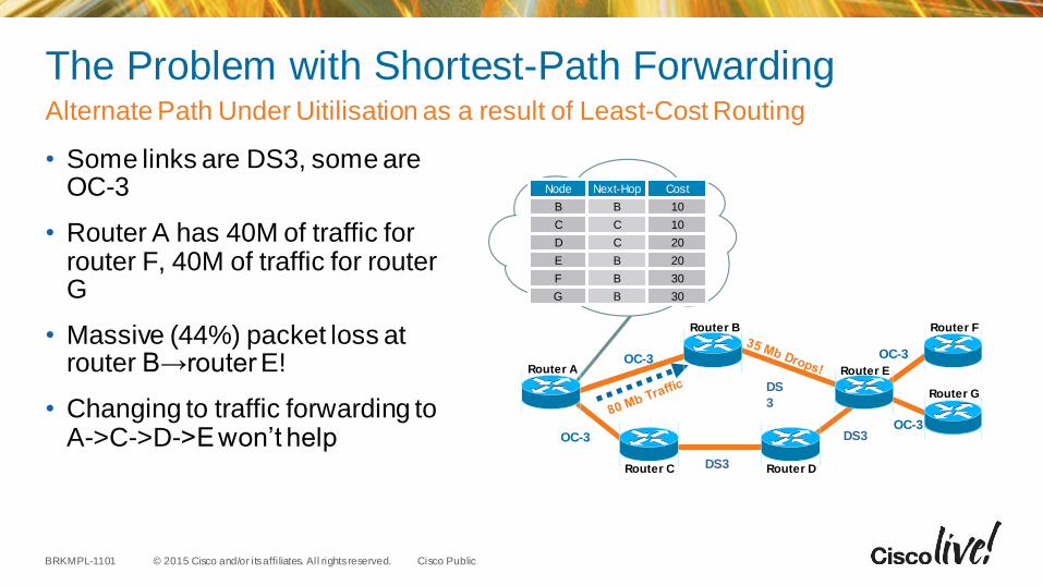
The Problem with Shortest-Path Forwarding
• Some links are DS3, some are OC-3
• Router A has 40M of traffic for router F, 40M of traffic for router G
• Massive (44%) packet loss at router B→router E!
• Changing to traffic forwarding to A->C->D->E won’t help
Alternate Path Under Uitilisation as a result of Least-Cost Routing
Router F
Router C Router D
Router A
Router B
OC-3
OC-3
DS
3
DS3
DS3OC-3
OC-3
Router E
Router G
Node Next-Hop Cost
B B 10
C C 10
D C 20
E B 20
F B 30
G B 30
© 2015 Cisco and/or its affi liates. All rights reserved.BRKMPL-1101 Cisco Public
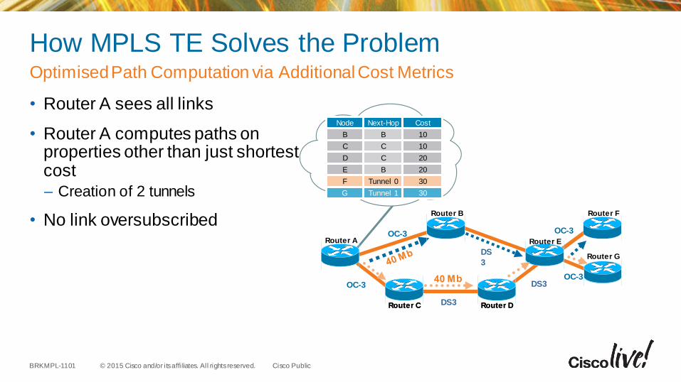
How MPLS TE Solves the Problem
• Router A sees all links
• Router A computes paths on properties other than just shortest cost– Creation of 2 tunnels
• No link oversubscribed
OptimisedPath Computation via Additional Cost Metrics
Router C Router D
OC-3
OC-3
DS
3
DS3
DS3OC-3
OC-3
Router F
Router C Router D
Router G
Router A
Router B
Router E
Node Next-Hop Cost
B B 10
C C 10
D C 20
E B 20
F Tunnel 0 30
G Tunnel 1 30
© 2015 Cisco and/or its affi liates. All rights reserved.BRKMPL-1101 Cisco Public
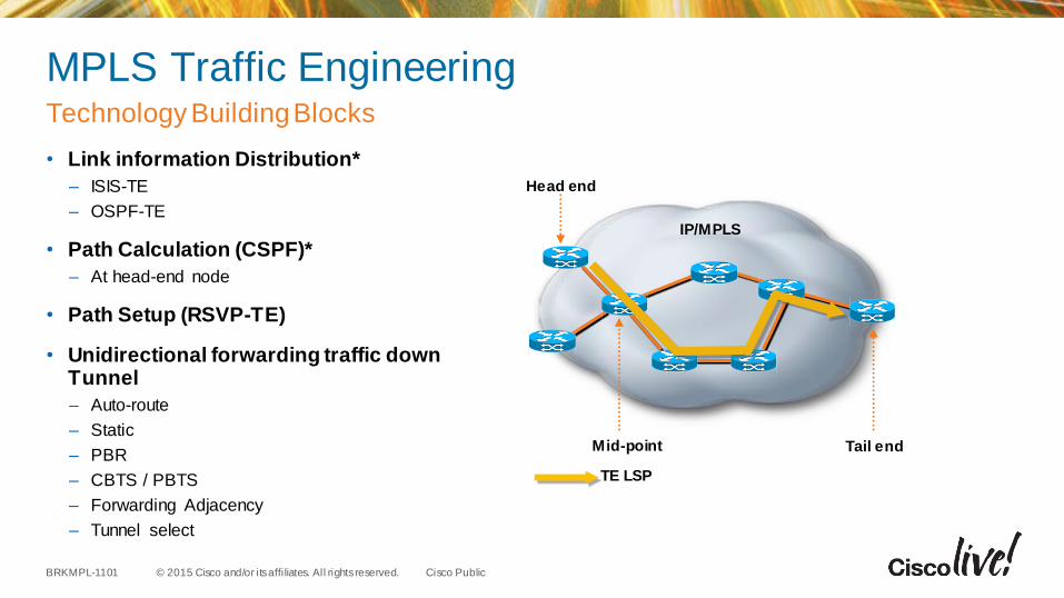
MPLS Traffic Engineering
• Link information Distribution*
– ISIS-TE
– OSPF-TE
• Path Calculation (CSPF)*
– At head-end node
• Path Setup (RSVP-TE)
• Unidirectional forwarding traffic down Tunnel
– Auto-route
– Static
– PBR
– CBTS / PBTS
– Forwarding Adjacency
– Tunnel select
Technology Building Blocks
IP/MPLS
Head end
Mid-point Tail end
TE LSP
© 2015 Cisco and/or its affi liates. All rights reserved.BRKMPL-1101 Cisco Public
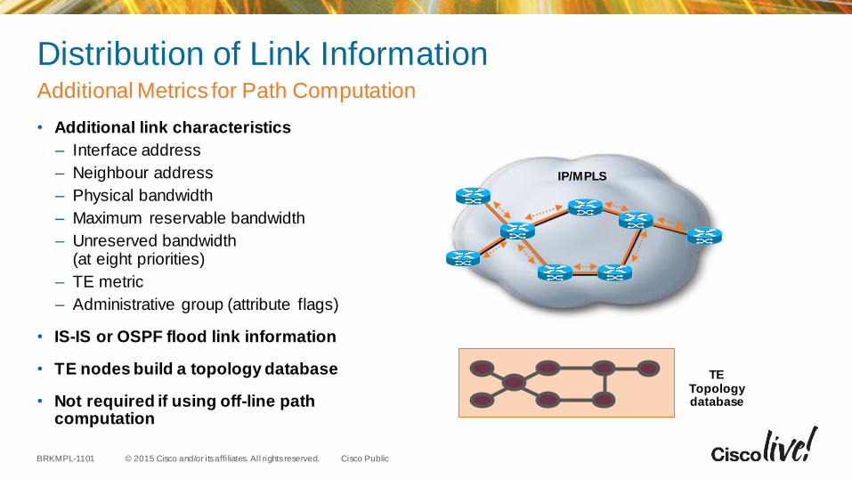
Distribution of Link Information
• Additional link characteristics
– Interface address
– Neighbour address
– Physical bandwidth
– Maximum reservable bandwidth
– Unreserved bandwidth (at eight priorities)
– TE metric
– Administrative group (attribute flags)
• IS-IS or OSPF flood link information
• TE nodes build a topology database
• Not required if using off-line path computation
Additional Metrics for Path Computation
IP/MPLS
TE Topology database
© 2015 Cisco and/or its affi liates. All rights reserved.BRKMPL-1101 Cisco Public
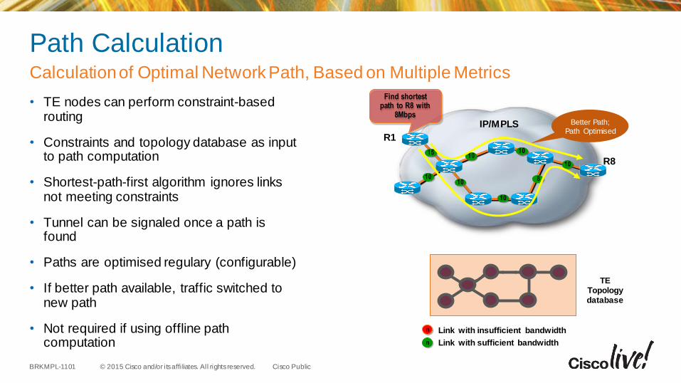
Path Calculation
• TE nodes can perform constraint-based routing
• Constraints and topology database as input to path computation
• Shortest-path-first algorithm ignores links not meeting constraints
• Tunnel can be signaled once a path is found
• Paths are optimised regulary (configurable)
• If better path available, traffic switched to new path
• Not required if using offline path computation
Calculation of Optimal Network Path, Based on Multiple Metrics
TE Topology database
Link with insufficient bandwidth
Link with sufficient bandwidth
n
n
IP/MPLS
53
10
15
10
10
8
10
R1
R8
Find shortest path to R8 with
8Mbps
1010
Better Path;
Path Optimised
© 2015 Cisco and/or its affi liates. All rights reserved.BRKMPL-1101 Cisco Public
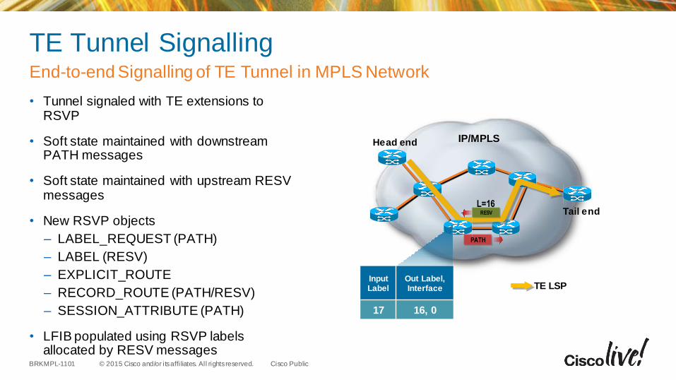
TE Tunnel Signalling
• Tunnel signaled with TE extensions to RSVP
• Soft state maintained with downstream PATH messages
• Soft state maintained with upstream RESV messages
• New RSVP objects
– LABEL_REQUEST (PATH)
– LABEL (RESV)
– EXPLICIT_ROUTE
– RECORD_ROUTE (PATH/RESV)
– SESSION_ATTRIBUTE (PATH)
• LFIB populated using RSVP labels allocated by RESV messages
End-to-end Signalling of TE Tunnel in MPLS Network
IP/MPLSHead end
Tail end
PATH
RESV
L=16
TE LSPInput Label
Out Label, Interface
17 16, 0
© 2015 Cisco and/or its affi liates. All rights reserved.BRKMPL-1101 Cisco Public
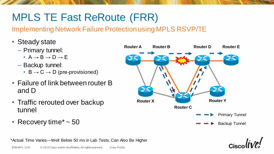
MPLS TE Fast ReRoute (FRR)
• Steady state– Primary tunnel:
• A → B → D → E
– Backup tunnel: • B → C → D (pre-provisioned)
• Failure of link between router B and D
• Traffic rerouted over backup tunnel
• Recovery time* ~ 50
Implementing Network Failure Protection using MPLS RSVP/TE
*Actual Time Varies—Well Below 50 ms in Lab Tests, Can Also Be Higher
Router D
Router C
Router A Router B Router E
Router YRouter X
Primary Tunnel
Backup Tunnel
© 2015 Cisco and/or its affi liates. All rights reserved.BRKMPL-1101 Cisco Public
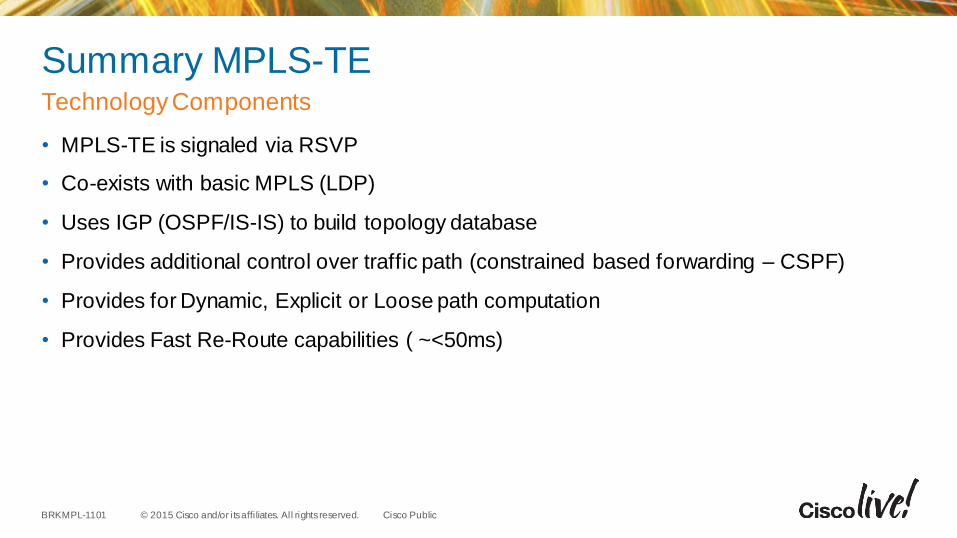
Summary MPLS-TE
• MPLS-TE is signaled via RSVP
• Co-exists with basic MPLS (LDP)
• Uses IGP (OSPF/IS-IS) to build topology database
• Provides additional control over traffic path (constrained based forwarding – CSPF)
• Provides for Dynamic, Explicit or Loose path computation
• Provides Fast Re-Route capabilities ( ~<50ms)
Technology Components

Summary
© 2015 Cisco and/or its affi liates. All rights reserved.BRKMPL-1101 Cisco Public
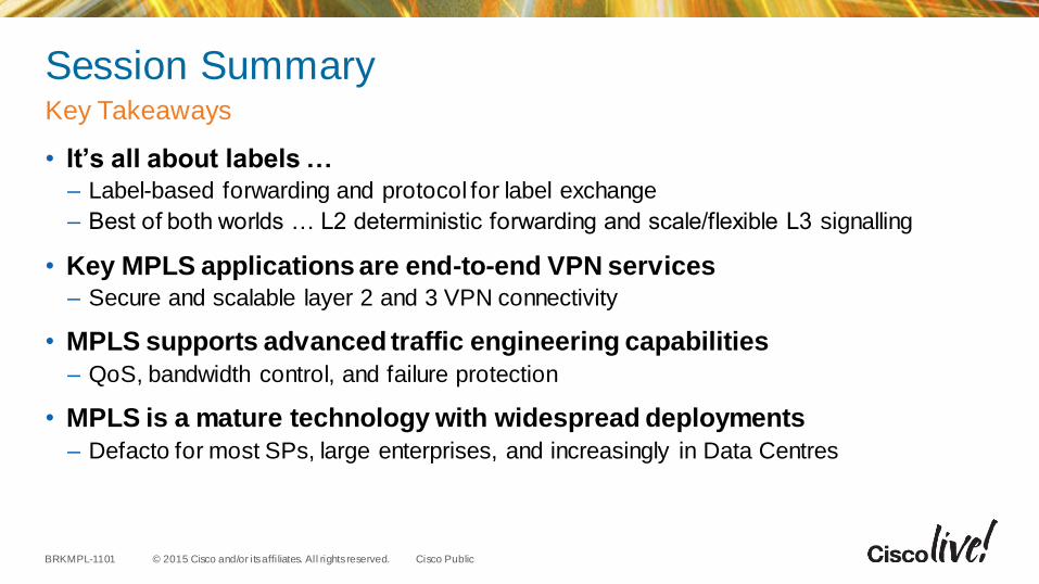
Session Summary
• It’s all about labels … – Label-based forwarding and protocol for label exchange
– Best of both worlds … L2 deterministic forwarding and scale/flexible L3 signalling
• Key MPLS applications are end-to-end VPN services– Secure and scalable layer 2 and 3 VPN connectivity
• MPLS supports advanced traffic engineering capabilities
– QoS, bandwidth control, and failure protection
• MPLS is a mature technology with widespread deployments
– Defacto for most SPs, large enterprises, and increasingly in Data Centres
Key Takeaways
© 2015 Cisco and/or its affi liates. All rights reserved.BRKMPL-1101 Cisco Public
Cisco Live Sessions
• Segment Routing and SDN– BRKRST-3370 – Advances In Routing
• IPv6 Deployment– BRKSPG-3300 – Service Provider IPv6 Deployment
• Cloud Enablement Architecture
– BRKSPG-3864 - Cloud Enablement Architecture and NFV Services Delivery
Recommended

Q & A
© 2015 Cisco and/or its affi liates. All rights reserved.BRKMPL-1101 Cisco Public
Give us your feedback and receive a
Cisco Live 2015 T-Shirt!
Complete your Overall Event Survey and 5 Session
Evaluations.
• Directly from your mobile device on the Cisco Live
Mobile App
• By visiting the Cisco Live Mobile Site
http://showcase.genie-connect.com/clmelbourne2015
• Visit any Cisco Live Internet Station located
throughout the venue
T-Shirts can be collected in the World of Solutions
on Friday 20 March 12:00pm - 2:00pm
Complete Your Online Session Evaluation
Learn online with Cisco Live! Visit us online after the conference for full
access to session videos and
presentations. www.CiscoLiveAPAC.com

Thank you.


References
© 2015 Cisco and/or its affi liates. All rights reserved.BRKMPL-1101 Cisco Public
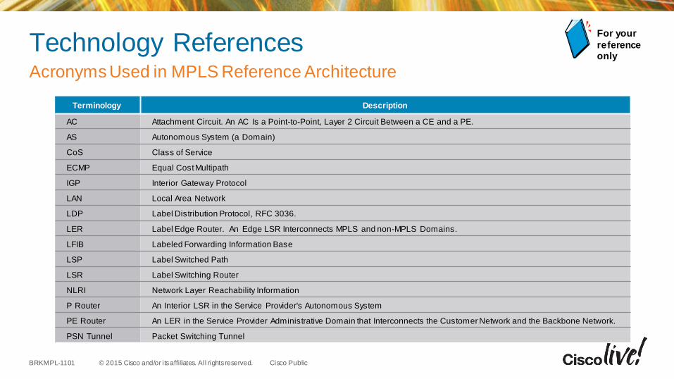
Technology ReferencesAcronyms Used in MPLS Reference Architecture
Terminology Description
AC Attachment Circuit. An AC Is a Point-to-Point, Layer 2 Circuit Between a CE and a PE.
AS Autonomous System (a Domain)
CoS Class of Service
ECMP Equal Cost Multipath
IGP Interior Gateway Protocol
LAN Local Area Network
LDP Label Distribution Protocol, RFC 3036.
LER Label Edge Router. An Edge LSR Interconnects MPLS and non-MPLS Domains.
LFIB Labeled Forwarding Information Base
LSP Label Switched Path
LSR Label Switching Router
NLRI Network Layer Reachability Information
P Router An Interior LSR in the Service Provider's Autonomous System
PE Router An LER in the Service Provider Administrative Domain that Interconnects the Customer Network and the Backbone Network.
PSN Tunnel Packet Switching Tunnel
For your
reference only
© 2015 Cisco and/or its affi liates. All rights reserved.BRKMPL-1101 Cisco Public
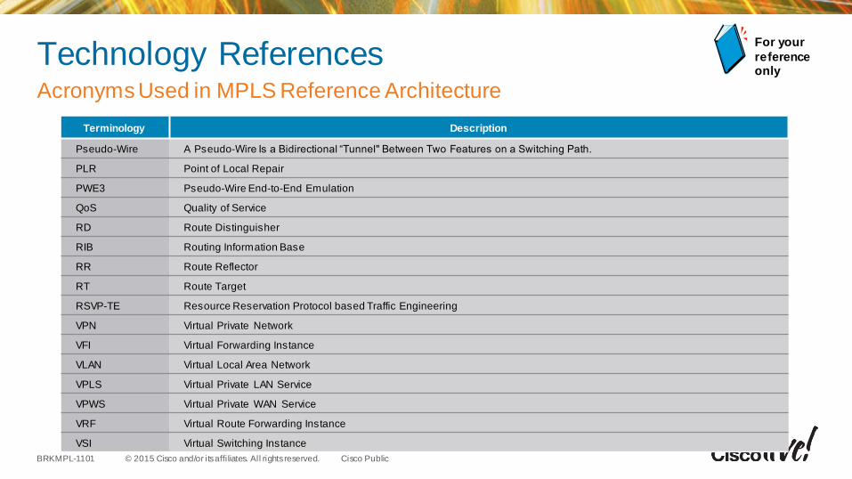
Technology ReferencesAcronyms Used in MPLS Reference Architecture
For your
reference only
Terminology Description
Pseudo-Wire A Pseudo-Wire Is a Bidirectional “Tunnel" Between Two Features on a Switching Path.
PLR Point of Local Repair
PWE3 Pseudo-Wire End-to-End Emulation
QoS Quality of Service
RD Route Distinguisher
RIB Routing Information Base
RR Route Reflector
RT Route Target
RSVP-TE Resource Reservation Protocol based Traffic Engineering
VPN Virtual Private Network
VFI Virtual Forwarding Instance
VLAN Virtual Local Area Network
VPLS Virtual Private LAN Service
VPWS Virtual Private WAN Service
VRF Virtual Route Forwarding Instance
VSI Virtual Switching Instance
© 2015 Cisco and/or its affi liates. All rights reserved.BRKMPL-1101 Cisco Public
Further Reading
• http://www.cisco.com/go/mpls
• http://www.ciscopress.com
• MPLS and VPN Architectures — Cisco Press®
– Jim Guichard, Ivan Papelnjak
• Traffic Engineering with MPLS — Cisco Press®
– Eric Osborne, Ajay Simha
• Layer 2 VPN Architectures — Cisco Press®
– Wei Luo, Carlos Pignataro, Dmitry Bokotey, and Anthony Chan
• MPLS QoS — Cisco Press ®– Santiago Alvarez
MPLS References at Cisco Press and cisco.com
© 2015 Cisco and/or its affi liates. All rights reserved.BRKMPL-1101 Cisco Public
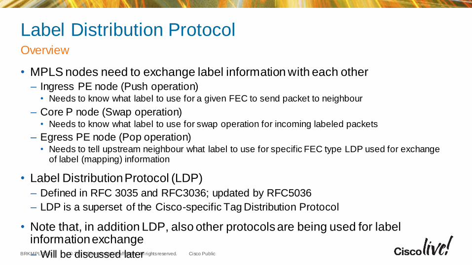
Label Distribution Protocol
• MPLS nodes need to exchange label information with each other– Ingress PE node (Push operation)
• Needs to know what label to use for a given FEC to send packet to neighbour
– Core P node (Swap operation)• Needs to know what label to use for swap operation for incoming labeled packets
– Egress PE node (Pop operation)• Needs to tell upstream neighbour what label to use for specific FEC type LDP used for exchange
of label (mapping) information
• Label Distribution Protocol (LDP)
– Defined in RFC 3035 and RFC3036; updated by RFC5036
– LDP is a superset of the Cisco-specific Tag Distribution Protocol
• Note that, in addition LDP, also other protocols are being used for label information exchange
– Will be discussed later
Overview
© 2015 Cisco and/or its affi liates. All rights reserved.BRKMPL-1101 Cisco Public
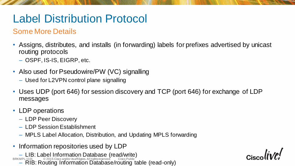
Label Distribution Protocol
• Assigns, distributes, and installs (in forwarding) labels for prefixes advertised by unicast routing protocols
– OSPF, IS-IS, EIGRP, etc.
• Also used for Pseudowire/PW (VC) signalling
– Used for L2VPN control plane signalling
• Uses UDP (port 646) for session discovery and TCP (port 646) for exchange of LDP messages
• LDP operations
– LDP Peer Discovery
– LDP Session Establishment
– MPLS Label Allocation, Distribution, and Updating MPLS forwarding
• Information repositories used by LDP
– LIB: Label Information Database (read/write)
– RIB: Routing Information Database/routing table (read-only)
Some More Details
© 2015 Cisco and/or its affi liates. All rights reserved.BRKMPL-1101 Cisco Public
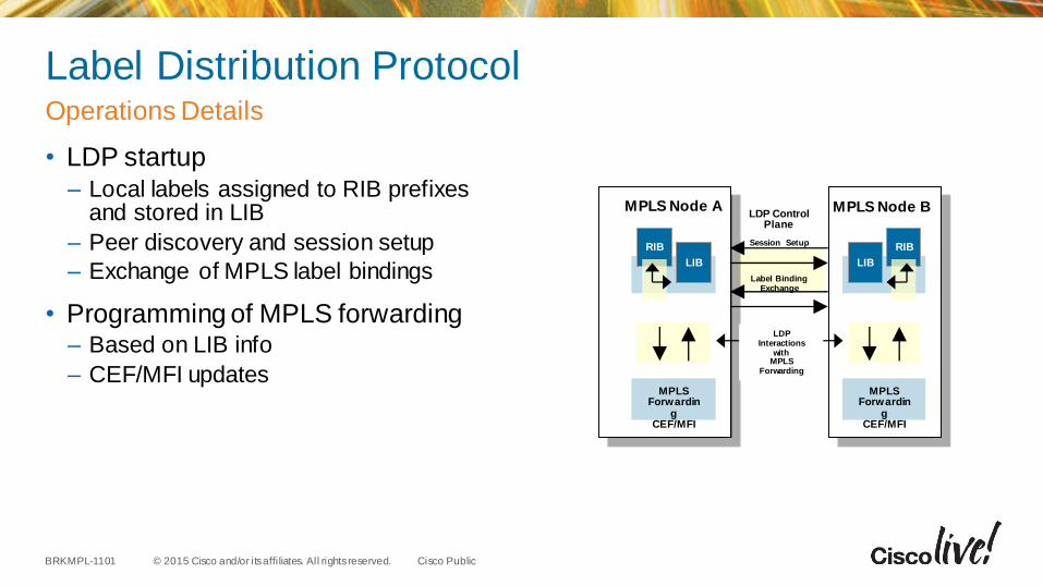
Label Distribution Protocol
• LDP startup– Local labels assigned to RIB prefixes
and stored in LIB
– Peer discovery and session setup
– Exchange of MPLS label bindings
• Programming of MPLS forwarding– Based on LIB info
– CEF/MFI updates
Operations Details
LDP Control Plane
MPLS Node A MPLS Node B
Session Setup
Label Binding Exchange
MPLS Forwardin
gCEF/MFI
RIB
LIB
MPLS Forwardin
gCEF/MFI
LDP Interactions
with MPLS
Forwarding
LIB
RIB
© 2015 Cisco and/or its affi liates. All rights reserved.BRKMPL-1101 Cisco Public
Why MPLS QoS
• Typically different traffic types (packets) sent over MPLS networks– E.g., Web HTTP, VoIP, FTP, etc.
• Not all traffic types/flows have the same performance requirements …– Some require low latency to work correctly; e.g., video
• MPLS QoS used for traffic prioritisation to guarantee minimal traffic loss and delay for high priority traffic– Involves packet classification and queuing
• MPLS leverages mostly existing IP QoS architecture– Based on Differentiated Services (DiffServ) model; defines per-hop behaviour based on
IP Type of Service (ToS) field
The Need for Differentiated Services
© 2015 Cisco and/or its affi liates. All rights reserved.BRKMPL-1101 Cisco Public
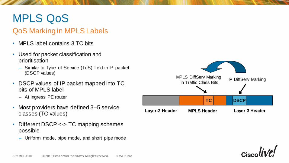
MPLS QoS
• MPLS label contains 3 TC bits
• Used for packet classification and prioritisation
– Similar to Type of Service (ToS) field in IP packet (DSCP values)
• DSCP values of IP packet mapped into TC bits of MPLS label
– At ingress PE router
• Most providers have defined 3–5 service classes (TC values)
• Different DSCP <-> TC mapping schemes possible
– Uniform mode, pipe mode, and short pipe mode
QoS Marking in MPLS Labels
MPLS HeaderLayer-2 Header Layer 3 Header
MPLS DiffServ Marking
in Traffic Class BitsIP DiffServ Marking
TC DSCP
© 2015 Cisco and/or its affi liates. All rights reserved.BRKMPL-1101 Cisco Public
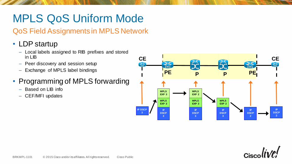
MPLS QoS Uniform Mode
• LDP startup– Local labels assigned to RIB prefixes and stored
in LIB
– Peer discovery and session setup
– Exchange of MPLS label bindings
• Programming of MPLS forwarding– Based on LIB info
– CEF/MFI updates
QoS Field Assignments in MPLS Network
PPPE PE
CE CE
IP DSCP
3IP
DSCP
3
MPLS
EXP 3
MPLS
EXP 3
IP
DSCP
2
IP
DSCP
3
MPLS
EXP 3
MPLS
EXP 2
IP
DSCP
3
MPLS
EXP 2
IP
DSCP
2
© 2015 Cisco and/or its affi liates. All rights reserved.BRKMPL-1101 Cisco Public
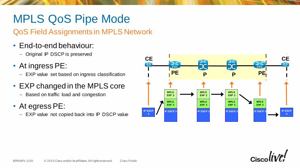
MPLS QoS Pipe Mode
• End-to-end behaviour: – Original IP DSCP is preserved
• At ingress PE:– EXP value set based on ingress classification
• EXP changed in the MPLS core – Based on traffic load and congestion
• At egress PE:– EXP value not copied back into IP DSCP value
QoS Field Assignments in MPLS Network
PPPE PE
CE CE
IP DSCP
3IP DSCP 3
MPLS
EXP 3
MPLS
EXP 3
IP DSCP
3IP DSCP 3
MPLS
EXP 3
MPLS
EXP 2
IP DSCP 3
MPLS
EXP 2
IP DSCP 3
MPLS
EXP 3
MPLS
EXP 2
© 2015 Cisco and/or its affi liates. All rights reserved.BRKMPL-1101 Cisco Public
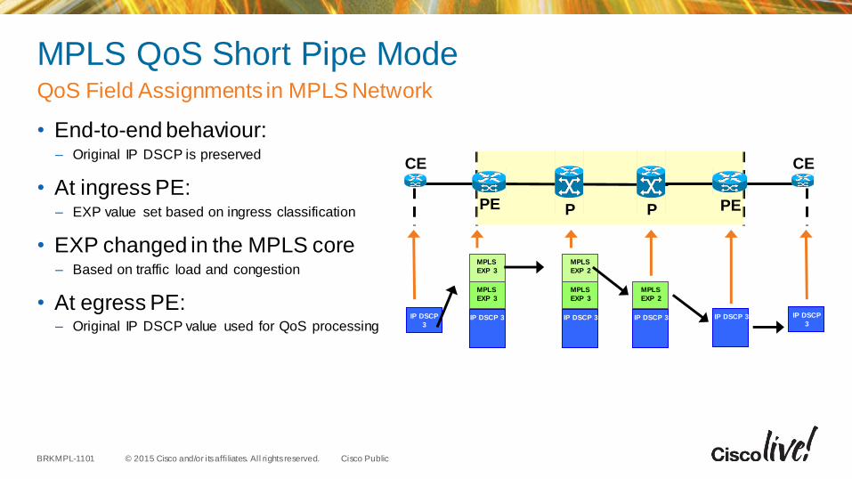
MPLS QoS Short Pipe Mode
• End-to-end behaviour:– Original IP DSCP is preserved
• At ingress PE:– EXP value set based on ingress classification
• EXP changed in the MPLS core – Based on traffic load and congestion
• At egress PE:– Original IP DSCP value used for QoS processing
QoS Field Assignments in MPLS Network
PPPE PE
CE CE
IP DSCP
3IP DSCP 3
MPLS
EXP 3
MPLS
EXP 3
IP DSCP
3IP DSCP 3
MPLS
EXP 3
MPLS
EXP 2
IP DSCP 3
MPLS
EXP 2
IP DSCP 3
© 2015 Cisco and/or its affi liates. All rights reserved.BRKMPL-1101 Cisco Public
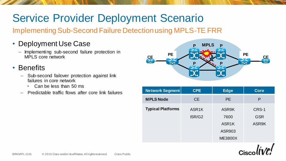
Service Provider Deployment Scenario
• Deployment Use Case– Implementing sub-second failure protection in
MPLS core network
• Benefits– Sub-second failover protection against link
failures in core network
• Can be less than 50 ms
– Predictable traffic flows after core link failures
Implementing Sub-Second Failure Detection using MPLS-TE FRR
MPLS
PECE CE
Network Segment CPE Edge Core
MPLS Node CE PE P
Typical Platforms ASR1K
ISR/G2
ASR9K
7600
ASR1K
ASR903
ME3800X
CRS-1
GSR
ASR9K
PE
P P
P P
© 2015 Cisco and/or its affi liates. All rights reserved.BRKMPL-1101 Cisco Public
Summary Layer 3 VPN
• MPLS Layer-3 VPNs provide IP connectivity among CE sites – MPLS VPNs enable full-mesh, hub-and-spoke, and hybrid IP connectivity
• CE sites connect to the MPLS network via IP peering across PE-CE links
• MPLS Layer-3 VPNs are implemented via VRFs on PE edge nodes – VRFs providing customer routing and forwarding segmentation
• BGP used for signalling customer VPN (VPNv4) routes between PE nodes
• To ensure traffic separation, customer traffic is encapsulated in an additional VPN label when forwarded in MPLS network
• Key applications are layer-3 business VPN services, enterprise network segmentation, and segmented layer-3 Data Centre access
81
Key Takeaways

Advanced Topics
© 2015 Cisco and/or its affi liates. All rights reserved.BRKMPL-1101 Cisco Public
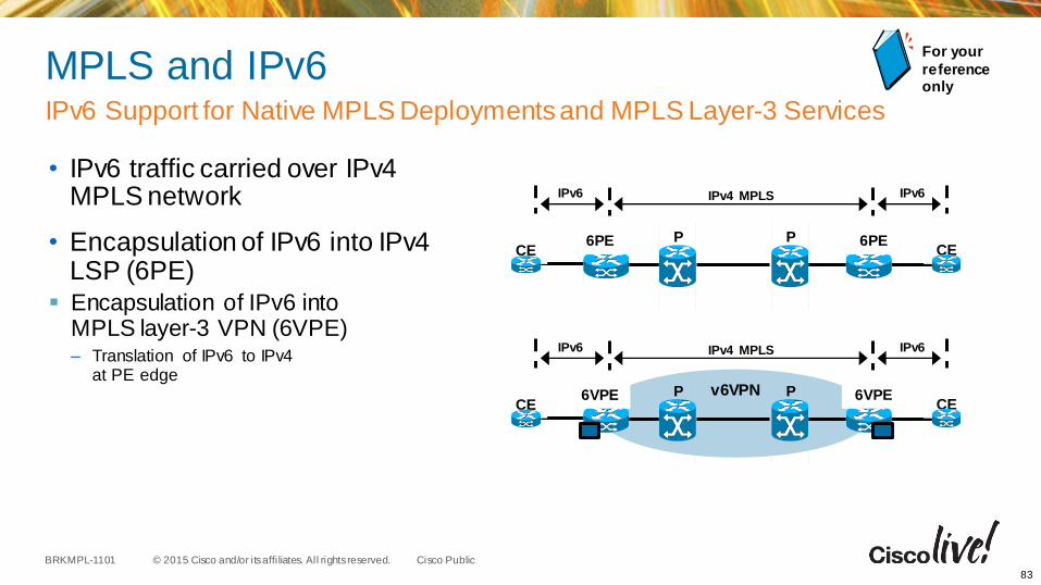
MPLS and IPv6
• IPv6 traffic carried over IPv4 MPLS network
• Encapsulation of IPv6 into IPv4 LSP (6PE)
Encapsulation of IPv6 into MPLS layer-3 VPN (6VPE)– Translation of IPv6 to IPv4
at PE edge
For your
reference only
83
P6PE PCE
6PECE
IPv6 IPv4 MPLS IPv6
v6VPNP6VPE PCE
6VPECE
IPv6 IPv4 MPLS IPv6
IPv6 Support for Native MPLS Deployments and MPLS Layer-3 Services
© 2015 Cisco and/or its affi liates. All rights reserved.BRKMPL-1101 Cisco Public
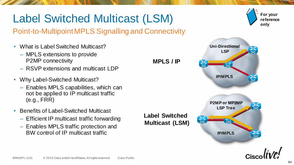
Label Switched Multicast (LSM)
• What is Label Switched Multicast?
– MPLS extensions to provideP2MP connectivity
– RSVP extensions and multicast LDP
• Why Label-Switched Multicast?
– Enables MPLS capabilities, which can not be applied to IP multicast traffic (e.g., FRR)
• Benefits of Label-Switched Multicast
– Efficient IP multicast traffic forwarding
– Enables MPLS traffic protection and BW control of IP multicast traffic
For your
reference only
84
IP/MPLS
Uni-Directional
LSP
IP/MPLS
P2MP or MP2MP
LSP Tree
MPLS / IP
Label Switched
Multicast (LSM)
Point-to-Multipoint MPLS Signalling and Connectivity
© 2015 Cisco and/or its affi liates. All rights reserved.BRKMPL-1101 Cisco Public
MPLS SNMP MIBs
• MPLS-LSR-STD-MIB– Provides LSP end-point and LSP cross-connect information
• MPLS-LDP-STD-MIB– Provides LDP session configuration and status information
– Frequently used: LDP session status Trap notifications
• MPLS-L3VPN-STD-MIB– Provides VRF configuration and status information and associated interface mappings
– Frequently used: VRF max-route Trap notifications
• MPLS-TE-STD-MIB– Provides TE tunnel configuration and status information
– Frequently used: TE Tunnel status Trap notifications
85
SNMP Management Access to MPLS Resources
© 2015 Cisco and/or its affi liates. All rights reserved.BRKMPL-1101 Cisco Public
MPLS OAM
• MPLS LSP Ping– Used for testing end-to-end MPLS connectivity similar to IP ping
– Can we used to validate reach ability of LDP-signaled LSPs, TE tunnels, and PWs
• MPLS LSP Trace– Used for testing hop-by-hop tracing of MPLS path similar to traceroute
– Can we used for path tracing LDP-signaled LSPs and TE tunnels
• MPLS LSP Multipath (ECMP) Tree Trace– Used to discover of all available equal cost LSP paths between PEs
– Unique capability for MPLS OAM; no IP equivalent!
86
Tools for Reactive and Proactive Troubleshooting of MPLS Connectivity
Recommended