UNDERSTANDING SAFETY INTEGRITY LEVEL
S p e c i a l A p p l i c at i o n S e r i e s
M I L E S T O N E
TUV (Bavaria) Microcomputers inSafety-Related Systems (1984)
Health & Safety Executive (UK)
Programmable Electronic Systems in
Safety Related Applications (1987)
OSHA (29 CFR 1910.119) (1992):
Process Safety Management of
Highly Hazardous Chemicals
Instrument Society of America
ANSI/ISA 84 (2004):
Safety Instrumented Systems for
the Process Industries
International Electrotechnical
Commission (1998-2003)
IEC 61508 (2000): A general
approach to Functional Safety Systems
IEC 61511 (2003): Process sector
implementation of IEC 61508
On the morning of 12/11/05, the largest detonation sincethe end of WWII rocked the Buncefield Petrol Depot north ofLondon. 72 million gallons of fuel ignited causing a shockthat registered 2.4 on the Richter scale. Catastrophic eventslike Buncefield, Texas City and Bhopal are what the informa-tion in this brochure is meant to prevent.
Industrial safety in pre-digital eras centered mainly around safe work
practices, hazardous materials control, and the protective “armoring”
of personnel and equipment. Today, safety penetrates far deeper into
more complex manufacturing infrastructures, extending its protective
influence all the way to a company’s bottom line. Contemporary safety
systems reduce risk with operational advancements that frequently
improve reliability, productivity and profitability as well.
Nothing is more important than safety to the process control industries.
High temperature and pressure, flammable and toxic materials are just
some of the issues faced on a daily basis. Reliability is a key component
of safety; the more reliable the device, the safer the critical process. After
years of work by the ISA SP84 committee, IEC 61508 and IEC 61511
have recently come together to yield a safety standard that the world is
embracing. IEC 61511 is particularly important as it is written specifical-
ly for the Process Industries. This standard quantifies safety issues as
never before. Although the safety issues addressed are critical to users
with installations like Emergency Shutdown Systems (ESD), the reliability
defined in this specification is being used by all users to separate great
products from good ones. SIL (Safety Integrity Level) and SFF (Safe
Failure Fraction) are two of the key values that customers can use as an
objective comparison of instrument reliability from various suppliers.
Reliability. Although this brochure targets safety applications and instal-
lations like Emergency Shutdown Systems, more than 90% of all applica-
tions are not safety-related. Those people are now using the SIL data as
an indicator for reliability, i.e., the better the numbers, the more reliable
the instrument.
THE NEW STANDARDS IN SAFETY
BuncefieldPetrol Depot Explosion
2
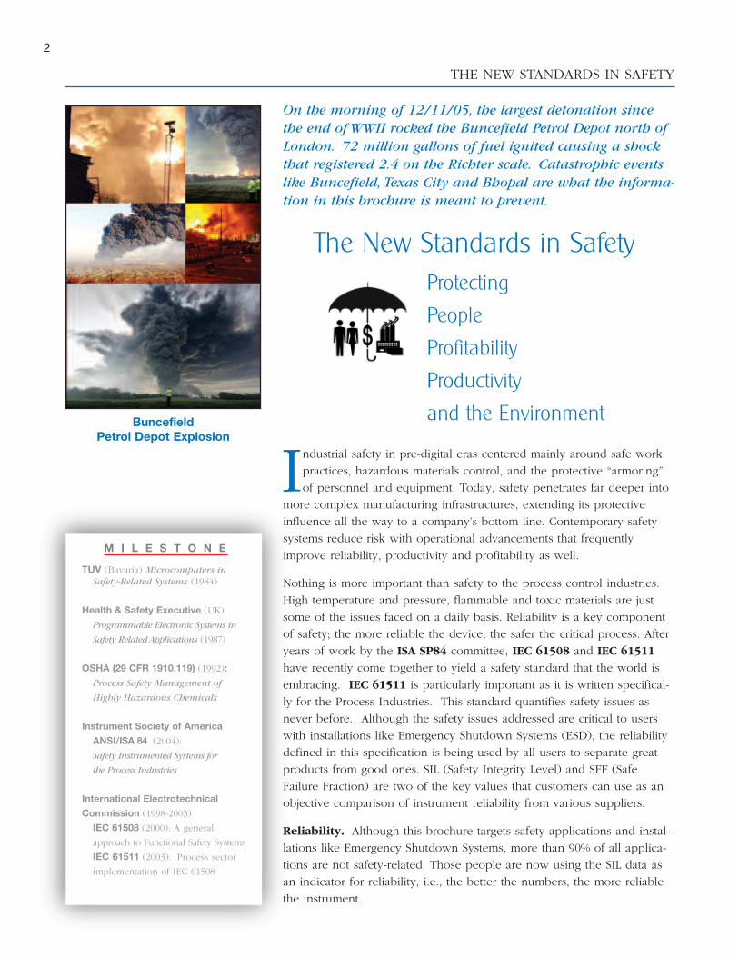
The New Standards in SafetyProtecting
People
Profitability
Productivity
and the Environment
Understanding Risk. All safety standards exist to reduce risk,
which is inherent wherever manufacturing or processing occurs.
The goal of eliminating risk and bringing about a state of absolute
safety is not attainable. More realistically, risk can be categorized as
being either negligible, tolerable or unacceptable. The foundation
for any modern safety system, then, is to reduce risk to an accept-
able or tolerable level. In this context, safety can be defined as
“freedom from unacceptable risk.”
The formula for risk is:
RISK = HAZARD FREQUENCY x HAZARD CONSEQUENCE
Risk can be minimized initially by inherently safe process design, by
the Basic Process Control System (BPCS), and finally by a safety
shutdown system.
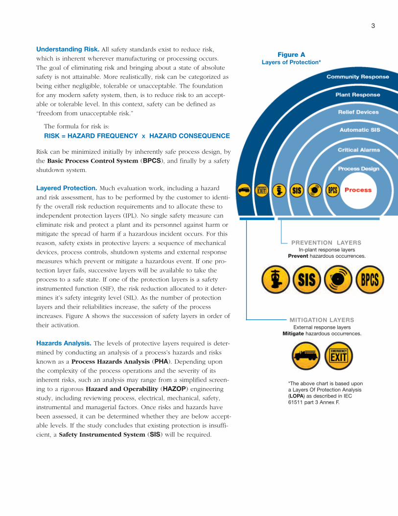
Layered Protection. Much evaluation work, including a hazard
and risk assessment, has to be performed by the customer to identi-
fy the overall risk reduction requirements and to allocate these to
independent protection layers (IPL). No single safety measure can
eliminate risk and protect a plant and its personnel against harm or
mitigate the spread of harm if a hazardous incident occurs. For this
reason, safety exists in protective layers: a sequence of mechanical
devices, process controls, shutdown systems and external response
measures which prevent or mitigate a hazardous event. If one pro-
tection layer fails, successive layers will be available to take the
process to a safe state. If one of the protection layers is a safety
instrumented function (SIF), the risk reduction allocated to it deter-
mines it’s safety integrity level (SIL). As the number of protection
layers and their reliabilities increase, the safety of the process
increases. Figure A shows the succession of safety layers in order of
their activation.
Hazards Analysis. The levels of protective layers required is deter-
mined by conducting an analysis of a process’s hazards and risks
known as a Process Hazards Analysis (PHA). Depending upon
the complexity of the process operations and the severity of its
inherent risks, such an analysis may range from a simplified screen-
ing to a rigorous Hazard and Operability (HAZOP) engineeringstudy, including reviewing process, electrical, mechanical, safety,
instrumental and managerial factors. Once risks and hazards have
been assessed, it can be determined whether they are below accept-
able levels. If the study concludes that existing protection is insuffi-
cient, a Safety Instrumented System (SIS) will be required.
In-plant response layersPrevent hazardous occurrences.
External response layersMitigate hazardous occurrences.
Figure ALayers of Protection*
PREVENTION LAYERS
MITIGATION LAYERS
3
*The above chart is based upona Layers Of Protection Analysis(LOPA) as described in IEC61511 part 3 Annex F.
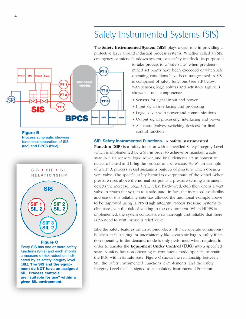
Safety Instrumented Systems (SIS)The Safety Instrumented System (SIS) plays a vital role in providing a
protective layer around industrial process systems. Whether called an SIS,
emergency or safety shutdown system, or a safety interlock, its purpose is
to take process to a “safe state” when pre-deter-
mined set points have been exceeded or when safe
operating conditions have been transgressed. A SIS
is comprised of safety functions (see SIF below)
with sensors, logic solvers and actuators. Figure B
shows its basic components:
• Sensors for signal input and power
• Input signal interfacing and processing
• Logic solver with power and communications
• Output signal processing, interfacing and power
• Actuators (valves, switching devices) for final
control function
SIF: Safety Instrumented Functions. A Safety Instrumented
Function (SIF) is a safety function with a specified Safety Integrity Level
which is implemented by a SIS in order to achieve or maintain a safe
state. A SIF’s sensors, logic solver, and final elements act in concert to
detect a hazard and bring the process to a safe state. Here’s an example
of a SIF: A process vessel sustains a buildup of pressure which opens a
vent valve. The specific safety hazard is overpressure of the vessel. When
pressure rises above the normal set points a pressure-sensing instrument
detects the increase. Logic (PLC, relay, hard-wired, etc.) then opens a vent
valve to return the system to a safe state. In fact, the increased availability
and use of this reliability data has allowed the traditional example above
to be improved using HIPPS (High Integrity Process Pressure System) to
eliminate even the risk of venting to the environment. When HIPPS is
implemented, the system controls are so thorough and reliable that there
is no need to vent, or use a relief valve.
Like the safety features on an automobile, a SIF may operate continuous-
ly like a car’s steering, or intermittently like a car’s air bag. A safety func-
tion operating in the demand mode is only performed when required in
order to transfer the Equipment Under Control (EUC) into a specified
state. A safety function operating in continuous mode operates to retain
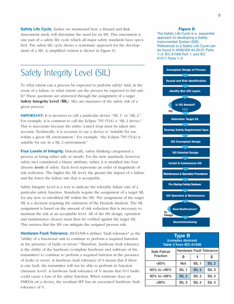
the EUC within its safe state. Figure C shows the relationship between
SIS, the Safety Instrumented Functions it implements, and the Safety
Integrity Level that’s assigned to each Safety Instrumented Function.
SIL 2SIF 1
SIS
Figure CEvery SIS has one or more safetyfunctions (SIFs) and each affordsa measure of risk reduction indi-cated by its safety integrity level(SIL). The SIS and the equip-ment do NOT have an assignedSIL. Process controlsare “suitable for use” within agiven SIL environment.
SIL 2SIF 2
SIL 2SIF 3
S I S • S I F • S I LR E L A T I O N S H I P
Figure BProcess schematic showingfunctional separation of SIS(red) and BPCS (blue).
4
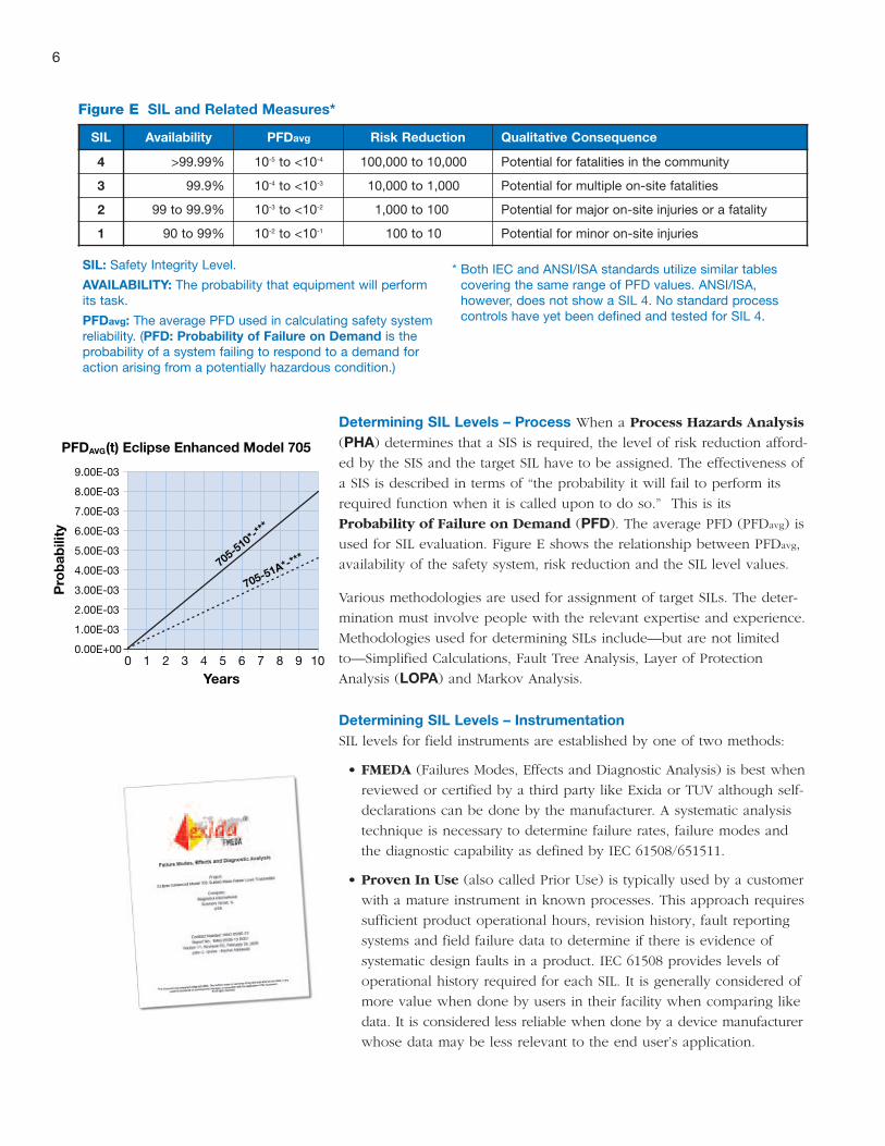
Safety Life Cycle. Earlier we mentioned how a Hazard and Risk
Assessment study will determine the need for an SIS. This assessment is
one part of a safety life cycle which all major safety standards have speci-
fied. The safety life cycle shows a systematic approach for the develop-
ment of a SIS. A simplified version is shown in Figure D.
Safety Integrity Level (SIL)To what extent can a process be expected to perform safely? And, in the
event of a failure, to what extent can the process be expected to fail safe-
ly? These questions are answered through the assignment of a target
Safety Integrity Level (SIL). SILs are measures of the safety risk of a
given process.
IMPORTANT: It is incorrect to call a particular device “SIL 1” or “SIL 2.”
For example, it is common to call the Eclipse 705 (51A) a “SIL 2 device.”
This is inaccurate because the entire control loop must be taken into
account. Technically, it is accurate to say a device is “suitable for use
within a given SIL environment.” For example, “the Eclipse 705 (51A) is
suitable for use in a SIL 2 environment.”
Four Levels of Integrity. Historically, safety thinking categorized a
process as being either safe or unsafe. For the new standards, however,
safety isn’t considered a binary attribute; rather, it is stratified into four
discrete levels of safety. Each level represents an order of magnitude of
risk reduction. The higher the SIL level, the greater the impact of a failure
and the lower the failure rate that is acceptable.
Safety Integrity Level is a way to indicate the tolerable failure rate of a
particular safety function. Standards require the assignment of a target SIL
for any new or retrofitted SIF within the SIS. The assignment of the target
SIL is a decision requiring the extension of the Hazards Analysis. The SIL
assignment is based on the amount of risk reduction that is necessary to
maintain the risk at an acceptable level. All of the SIS design, operation
and maintenance choices must then be verified against the target SIL.
This ensures that the SIS can mitigate the assigned process risk.
Hardware Fault Tolerance. IEC61508-4 defines "fault tolerance" as the
"ability of a functional unit to continue to perform a required function
in the presence of faults or errors." Therefore, hardware fault tolerance
is the ability of the hardware (complete hardware and software of the
transmitter) to continue to perform a required function in the presence
of faults or errors. A hardware fault tolerance of 0 means that if there
is one fault, the transmitter will not be able to perform its function
(measure level). A hardware fault tolerance of N means that N+1 faults
could cause a loss of the safety function. When someone does an
FMEDA on a device, the resultant SFF has an associated hardware fault
tolerance of 0.
Figure DThe Safety Life Cycle is a sequentialapproach to developing a SafetyInstrumented System (SIS).References to a Safety Life Cycle canbe found in ANSI/ISA 84.00.01 Parts1–3; IEC 61508 Part 1; and IEC61511 Parts 1–3.
5
Type B(complex devices)
Table 3 from IEC-61508
Safe FailureFraction
Hardware Fault Tolerance
0 1 2
<60% Not SIL 1 SIL 2
60% to <90% SIL 1 SIL 2 SIL 3
90% to <99% SIL 2 SIL 3 SIL 4
≥99% SIL 3 SIL 4 SIL 4
Determining SIL Levels – Process When a Process Hazards Analysis
(PHA) determines that a SIS is required, the level of risk reduction afford-
ed by the SIS and the target SIL have to be assigned. The effectiveness of
a SIS is described in terms of “the probability it will fail to perform its
required function when it is called upon to do so.” This is its
Probability of Failure on Demand (PFD). The average PFD (PFDavg) is
used for SIL evaluation. Figure E shows the relationship between PFDavg,
availability of the safety system, risk reduction and the SIL level values.
Various methodologies are used for assignment of target SILs. The deter-
mination must involve people with the relevant expertise and experience.
Methodologies used for determining SILs include—but are not limited
to—Simplified Calculations, Fault Tree Analysis, Layer of Protection
Analysis (LOPA) and Markov Analysis.
Determining SIL Levels – InstrumentationSIL levels for field instruments are established by one of two methods:
• FMEDA (Failures Modes, Effects and Diagnostic Analysis) is best when
reviewed or certified by a third party like Exida or TUV although self-
declarations can be done by the manufacturer. A systematic analysis
technique is necessary to determine failure rates, failure modes and
the diagnostic capability as defined by IEC 61508/651511.
• Proven In Use (also called Prior Use) is typically used by a customer
with a mature instrument in known processes. This approach requires
sufficient product operational hours, revision history, fault reporting
systems and field failure data to determine if there is evidence of
systematic design faults in a product. IEC 61508 provides levels of
operational history required for each SIL. It is generally considered of
more value when done by users in their facility when comparing like
data. It is considered less reliable when done by a device manufacturer
whose data may be less relevant to the end user’s application.
6
SIL Availability PFDavg Risk Reduction Qualitative Consequence
4 >99.99% 10-5 to <10-4 100,000 to 10,000 Potential for fatalities in the community
3 99.9% 10-4 to <10-3 10,000 to 1,000 Potential for multiple on-site fatalities
2 99 to 99.9% 10-3 to <10-2 1,000 to 100 Potential for major on-site injuries or a fatality
1 90 to 99% 10-2 to <10-1 100 to 10 Potential for minor on-site injuries
SIL: Safety Integrity Level.
AVAILABILITY: The probability that equipment will performits task.
PFDavg: The average PFD used in calculating safety systemreliability. (PFD: Probability of Failure on Demand is theprobability of a system failing to respond to a demand foraction arising from a potentially hazardous condition.)
* Both IEC and ANSI/ISA standards utilize similar tablescovering the same range of PFD values. ANSI/ISA,however, does not show a SIL 4. No standard processcontrols have yet been defined and tested for SIL 4.
Figure E SIL and Related Measures*
9.00E-03
8.00E-03
7.00E-03
6.00E-03
5.00E-03
4.00E-03
3.00E-03
2.00E-03
1.00E-03
0.00E+000 1 2 3 4 5 6 7 8 9 10
Years
PFDAVG(t) Eclipse Enhanced Model 705
Pro
bab
ility
705-510*-*
**
705-51A*-***
7
If you are using Manufacturer’s prior use data because a selected product
does not reach the required level under FMEDA analysis, be aware that
there are significant requirements on the end user. A mature product
must generally be used to have the required field experience, and the
design and assembly must be “frozen in time” in such a way that no
upgrades, modifications or even configuration changes may be allowed
that may render the “Proven In Use” data useless.
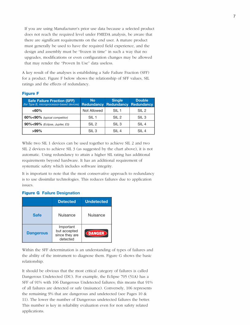
A key result of the analyses is establishing a Safe Failure Fraction (SFF)
for a product. Figure F below shows the relationship of SFF values, SIL
ratings and the effects of redundancy.
While two SIL 1 devices can be used together to achieve SIL 2 and two
SIL 2 devices to achieve SIL 3 (as suggested by the chart above), it is not
automatic. Using redundancy to attain a higher SIL rating has additional
requirements beyond hardware. It has an additional requirement of
systematic safety which includes software integrity.
It is important to note that the most conservative approach to redundancy
is to use dissimilar technologies. This reduces failures due to application
issues.
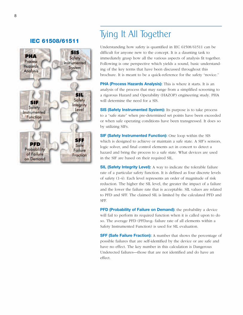
Within the SFF determination is an understanding of types of failures and
the ability of the instrument to diagnose them. Figure G shows the basic
relationship.
It should be obvious that the most critical category of failures is called
Dangerous Undetected (DU). For example, the Eclipse 705 (51A) has a
SFF of 91% with 106 Dangerous Undetected failures; this means that 91%
of all failures are detected or safe (nuisance). Conversely, 106 represents
the remaining 9% that are dangerous and undetected (see Pages 10 &
11). The lower the number of Dangerous undetected failures the better.
This number is key in reliability evaluation even for non safety related
applications.
Safe Failure Fraction (SFF)(for Type B, microprocessor-based devices)
NoRedundancy
SingleRedundancy
DoubleRedundancy
<60% Not Allowed SIL 1 SIL 2
60%<90% (typical competitor) SIL 1 SIL 2 SIL 3
90%<99% (Eclipse, Jupiter, E3) SIL 2 SIL 3 SIL 4
>99% SIL 3 SIL 4 SIL 4
Figure F
Detected Undetected
Safe Nuisance Nuisance
Dangerous
Importantbut acceptedsince they aredetected
Figure G Failure Designation
8
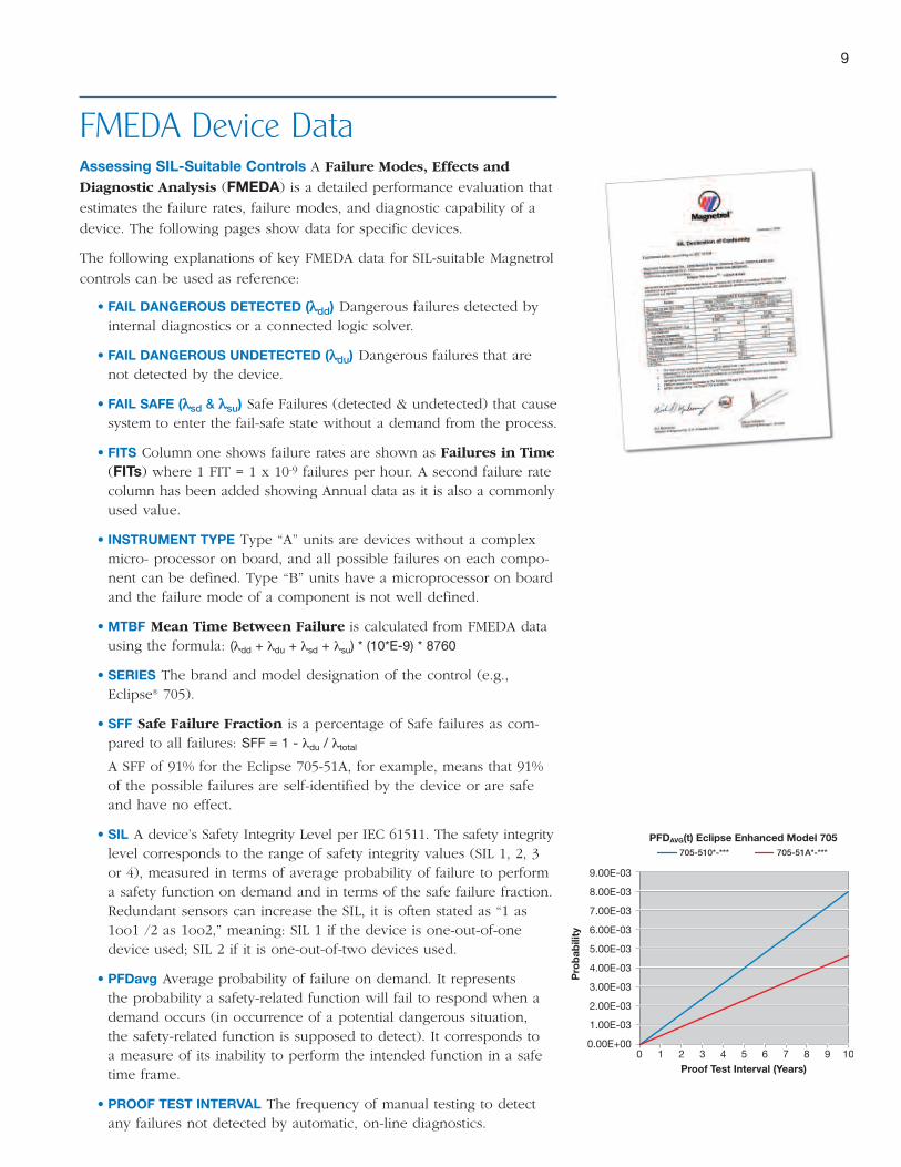
Tying It All TogetherUnderstanding how safety is quantified in IEC 61508/61511 can be
difficult for anyone new to the concept. It is a daunting task to
immediately grasp how all the various aspects of analysis fit together.
Following is one perspective which yields a sound, basic understand-
ing of the key terms that have been discussed throughout this
brochure. It is meant to be a quick-reference for the safety “novice.”
PHA (Process Hazards Analysis): This is where it starts. It is an
analysis of the process that may range from a simplified screening to
a rigorous Hazard and Operability (HAZOP) engineering study. PHA
will determine the need for a SIS.
SIS (Safety Instrumented System): Its purpose is to take process
to a “safe state” when pre-determined set points have been exceeded
or when safe operating conditions have been transgressed. It does so
by utilizing SIFs.
SIF (Safety Instrumented Function): One loop within the SIS
which is designed to achieve or maintain a safe state. A SIF’s sensors,
logic solver, and final control elements act in concert to detect a
hazard and bring the process to a safe state. What devices are used
in the SIF are based on their required SIL.
SIL (Safety Integrity Level): A way to indicate the tolerable failure
rate of a particular safety function. It is defined as four discrete levels
of safety (1-4). Each level represents an order of magnitude of risk
reduction. The higher the SIL level, the greater the impact of a failure
and the lower the failure rate that is acceptable. SIL values are related
to PFD and SFF. The claimed SIL is limited by the calculated PFD and
SFF.
PFD (Probability of Failure on Demand): the probability a device
will fail to perform its required function when it is called upon to do
so. The average PFD (PFDavg- failure rate of all elements within a
Safety Instrumented Function) is used for SIL evaluation.
SFF (Safe Failure Fraction): A number that shows the percentage of
possible failures that are self-identified by the device or are safe and
have no effect. The key number in this calculation is Dangerous
Undetected failures—those that are not identified and do have an
effect.
IEC 61508/61511
9
FMEDA Device DataAssessing SIL-Suitable Controls A Failure Modes, Effects and
Diagnostic Analysis (FMEDA) is a detailed performance evaluation that
estimates the failure rates, failure modes, and diagnostic capability of a
device. The following pages show data for specific devices.
The following explanations of key FMEDA data for SIL-suitable Magnetrol
controls can be used as reference:
• FAIL DANGEROUS DETECTED (λλdd) Dangerous failures detected byinternal diagnostics or a connected logic solver.
• FAIL DANGEROUS UNDETECTED (λλdu) Dangerous failures that arenot detected by the device.
• FAIL SAFE (λλsd & λλsu) Safe Failures (detected & undetected) that causesystem to enter the fail-safe state without a demand from the process.
• FITS Column one shows failure rates are shown as Failures in Time(FITs) where 1 FIT = 1 x 10⁻⁹ failures per hour. A second failure ratecolumn has been added showing Annual data as it is also a commonlyused value.
• INSTRUMENT TYPE Type “A” units are devices without a complexmicro- processor on board, and all possible failures on each compo-nent can be defined. Type “B” units have a microprocessor on boardand the failure mode of a component is not well defined.
• MTBF Mean Time Between Failure is calculated from FMEDA datausing the formula: (λdd + λdu + λsd + λsu) * (10*E-9) * 8760
• SERIES The brand and model designation of the control (e.g.,Eclipse® 705).
• SFF Safe Failure Fraction is a percentage of Safe failures as com-pared to all failures: SFF = 1 - λdu / λtotal
A SFF of 91% for the Eclipse 705-51A, for example, means that 91%of the possible failures are self-identified by the device or are safeand have no effect.
• SIL A device’s Safety Integrity Level per IEC 61511. The safety integritylevel corresponds to the range of safety integrity values (SIL 1, 2, 3or 4), measured in terms of average probability of failure to performa safety function on demand and in terms of the safe failure fraction.Redundant sensors can increase the SIL, it is often stated as “1 as1oo1 /2 as 1oo2,” meaning: SIL 1 if the device is one-out-of-onedevice used; SIL 2 if it is one-out-of-two devices used.
• PFDavg Average probability of failure on demand. It representsthe probability a safety-related function will fail to respond when ademand occurs (in occurrence of a potential dangerous situation,the safety-related function is supposed to detect). It corresponds toa measure of its inability to perform the intended function in a safetime frame.
• PROOF TEST INTERVAL The frequency of manual testing to detectany failures not detected by automatic, on-line diagnostics.
9.00E-03
8.00E-03
7.00E-03
6.00E-03
5.00E-03
4.00E-03
3.00E-03
2.00E-03
1.00E-03
0.00E+000
705-510*-*** 705-51A*-***
1 2 3 4 5 6 7 8 9 10
Pro
bab
ility
Proof Test Interval (Years)
PFDAVG(t) Eclipse Enhanced Model 705
SW
ITC
HES
TRA
NSM
ITTE
RS
10
Series and Description Model
Eclipse® Guided Wave Radar Level TransmitterThe Model 705 is a 24 VDC loop-powered transmitter that utilizes a variety of Coaxial,Twin, and Single rod probes. The performance of the Model 705 is not process depend-ent, and it is capable of measuring low dielectric liquids or solids.
705 (510)
705 (51A)
Pulsar® Thru-Air Radar Level TransmitterPulsar is the latest loop-powered, 24 VDC, thru-air radar transmitter. It offers fasterresponse time, easy operation and is not process dependent. 5.8/6.3 GHz offers superiorperformance in applications of turbulence, vapor, buildup and some foam.
RX5
Modulevel® Displacer Level TransmitterE3 takes displacer transmitters to the next level. Set up in as few as two steps withoutlevel movement. Microprocessor-based, HART, AMS and PACTware compatible, E3 offersstable, reliable 4-20 mA output in most applications, including interface.
E3
Aurora® Magnetic Level Indicator Aurora is a patented, redundant, Magnetic level Indicator combined with an EclipseGuided Wave Radar Transmitter. In the event of float failure, the Eclipse radar transmitterwill continue to provide an accurate 4-20 mA output signal.
705 (510)
705 (51A)
Jupiter® Magnetostrictive Level TransmitterA loop-powered level transmitter with HART communications, PACTware DTM interface,LCD display and push buttons for simple configuration. It may be externally mounted to aMLI or directly into a vessel.
20X/22X/24X
26X
TA2 Thermal Mass Flow MeterTA2 thermal mass flow meter provides reliable flow measurement of air and gases.Provides excellent low flow sensitivity, high turndown and low pressure drop. Pre-calibratedand configured for the user’s application. Integral or remote electronics.
TA2
Echotel® Compact Ultrasonic Level SwitchesEchotel Models 940/941 switches are economical and compact integral mount units.These switches utilize pulsed signal technology for superior performance in difficultprocess conditions.
940Relay
941Current Shift
Echotel Single Point Ultrasonic Level SwitchesEchotel Model 961 switches feature advanced self-testing that continuously monitors theelectronics, transducer and piezoelectric crystals. An adjustable time delay is provided forreliable measurement in turbulent processes.
961-5Current Shift
961-2/7Relay
Echotel Dual Point Ultrasonic Level SwitchesEchotel Model 962 switches are designed for dual point level measurement or pump con-trol. A tip sensitive lower gap allows measurement to within ¼" of the vessel bottom. Theflow-through upper gap allows up to a 125" (318 cm) separation between switch points.
962-5Current Shift
962-2/7Relay
External Cage Float Level SwitchesThese field-proven switches are self-contained units designed for external mounting onthe side of a vessel, tank or bridle. Over 30 models of mechanical switches have proventheir reliability and repeatability for decades in numerous applications.
SPDT
DPDT
Single-stage Displacer Level SwitchesModels A10, A15 and External Caged Displacer Switches offer reliable and repeatableoperation in sumps, storage and process vessels. Displacer switches offer flexibility inapplication and are not affected by dirty liquids, coating, foam, turbulence or agitation.
Low Level(DPDT)
High Level(DPDT)
Thermatel TD Series Flow, Level Interface SwitchesWith continuous self diagnostics these switches provide reliable operation for flow, level,or interface detection. Temperature compensation provides repeatable switch operationwith varying process temperature. Gas or liquid flow applications.
TD1
TD2
Thermatel TG Series Flow, Level Interface SwitchesProviding a two-wire intrinsically safe circuit between the probe and remote DIN rail enclo-sure these switches are suitable for liquid or gas flow, level, or interface detection. 24 VDCinput power, relay plus mA signal for flow trending/indication.
TG1/TG2
SIL-Suitable
Controls
• The SIL indicated below is per IEC 61508/61511.• Failure rates expressed in FITS and Annual.• PFDavg is calculated according to a proof test interval of one year, though other proof test intervalscan be applied.
• Transmitter failure rates assume the logic solver can detect both over-scale and under-scale currents.• Contact Magnetrol for complete FMEDA reports.
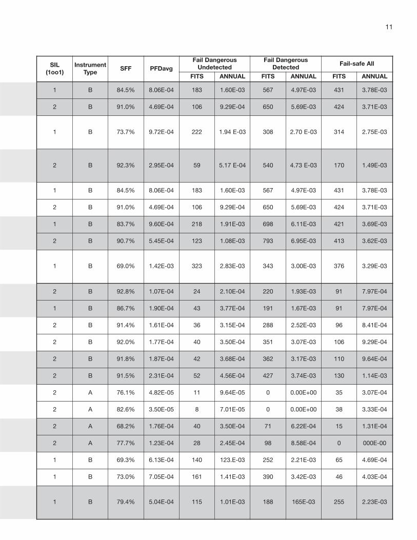
SIL(1oo1)
InstrumentType
SFF PFDavgFail Dangerous
UndetectedFail Dangerous
DetectedFail-safe All
FITS ANNUAL FITS ANNUAL FITS ANNUAL
1 B 84.5% 8.06E-04 183 1.60E-03 567 4.97E-03 431 3.78E-03
2 B 91.0% 4.69E-04 106 9.29E-04 650 5.69E-03 424 3.71E-03
1 B 73.7% 9.72E-04 222 1.94 E-03 308 2.70 E-03 314 2.75E-03
2 B 92.3% 2.95E-04 59 5.17 E-04 540 4.73 E-03 170 1.49E-03
1 B 84.5% 8.06E-04 183 1.60E-03 567 4.97E-03 431 3.78E-03
2 B 91.0% 4.69E-04 106 9.29E-04 650 5.69E-03 424 3.71E-03
1 B 83.7% 9.60E-04 218 1.91E-03 698 6.11E-03 421 3.69E-03
2 B 90.7% 5.45E-04 123 1.08E-03 793 6.95E-03 413 3.62E-03
1 B 69.0% 1.42E-03 323 2.83E-03 343 3.00E-03 376 3.29E-03
2 B 92.8% 1.07E-04 24 2.10E-04 220 1.93E-03 91 7.97E-04
1 B 86.7% 1.90E-04 43 3.77E-04 191 1.67E-03 91 7.97E-04
2 B 91.4% 1.61E-04 36 3.15E-04 288 2.52E-03 96 8.41E-04
2 B 92.0% 1.77E-04 40 3.50E-04 351 3.07E-03 106 9.29E-04
2 B 91.8% 1.87E-04 42 3.68E-04 362 3.17E-03 110 9.64E-04
2 B 91.5% 2.31E-04 52 4.56E-04 427 3.74E-03 130 1.14E-03
2 A 76.1% 4.82E-05 11 9.64E-05 0 0.00E+00 35 3.07E-04
2 A 82.6% 3.50E-05 8 7.01E-05 0 0.00E+00 38 3.33E-04
2 A 68.2% 1.76E-04 40 3.50E-04 71 6.22E-04 15 1.31E-04
2 A 77.7% 1.23E-04 28 2.45E-04 98 8.58E-04 0 000E-00
1 B 69.3% 6.13E-04 140 123.E-03 252 2.21E-03 65 4.69E-04
1 B 73.0% 7.05E-04 161 1.41E-03 390 3.42E-03 46 4.03E-04
1 B 79.4% 5.04E-04 115 1.01E-03 188 165E-03 255 2.23E-03
11
CORPORATE HEADQUARTERS5300 Belmont Road • Downers Grove, Illinois 60515-4499 USA
Phone: 630-969-4000 • Fax: 630-969-9489magnetrol.com • [email protected]
EUROPEAN HEADQUARTERSHeikensstraat 6 • 9240 Zele, Belgium
Phone: 052 45.11.11 • Fax: 052 45.09.93
BRAZIL: Av. Dr. Mauro Lindemberg Monteiro • 185-Jd. Santa Fé, Osasco • São Paulo CEP 06278-010
CANADA: 145 Jardin Drive, Units 1 & 2 • Concord, Ontario L4K 1X7
CHINA: Room #8008 • Overseas Chinese Mansion • 129 Yan An Road (W) • Shanghai 200040
DEUTSCHLAND: Alte Ziegelei 2–4 • D-51491 Overath
DUBAI: DAFZA Office 5AE 722, P.O. Box 293671 • Dubai, United Arab Emirates
INDIA: C-20 Community Centre • Janakpuri, New Delhi 110 021
ITALIA: Via Arese, 12 • 20159 Milano
SINGAPORE: No. 48 Toh Guan Road East #05-123 • Enterprise Hub • Singapore 608586
UNITED KINGDOM: Regent Business Centre • Jubilee Road • Burgess Hill, West Sussex RH15 9TL
Magnetrol & Magnetrol logotype, Echotel®, Eclipse®, Modulevel®, Thermatel®, Pulsar®,Aurora® and Jupiter® are trademarks of Magnetrol International.
PACTware™ is trademark of PACTware Consortium
Copyright © 2009 Magnetrol International. All rights reserved. Printed in the USA.Bulletin: 41-299.2 • Effective: February 2009
Visit magnetrol.com for more information on SIL-suitable Magnetrol controls including complete FMEDAreports. For further information regarding SIS, SIL and general process safety we recommend theseonline resources:
Subject: www:
IEC standards & bookstore...........................................................................iec.ch/home
ISA standards & bookstore ...........................................................................isa.org
Exida engineering guides..............................................................................exida.com
TUV functional safety services......................................................................tuv-global.com
UK Health & Safety Executive ......................................................................hse.gov.uk
Institution of Chemical Engineers .................................................................icheme.org
IHS/Global engineering documents..............................................................global.ihs.com
Factory Mutual process safety .....................................................................fm global.com
OSHA process safety standards...................................................................osha.gov
Center for Chemical Process Safety ............................................................aiche.org
S p e c i a l A p p l i c at i o n S e r i e s
Recommended