1
Sales Bulletin
Attention: All Furuno Distributors/Subsidiaries
SB No: FSB19-0008
Number of Pages: 20
Date: April 5, 2019
Unique, Advanced Technology in FURUNO Radar
1. Unique, Advanced Technology in FURUNO Radar
2. UHD & Auto by Digital Processing
3. RezBoost™
4. Target Analyzer by Doppler and Analog
4.1. Target Analyzer by Doppler – DRS4D-NXT and DRS6A-NXT
4.2. Target Analyzer by Analog – FAR-15xx and FAR-2xx8 (Non-IMO Mode)
5. ACE – Automatic Clutter Elimination
6. Sensitive Receiver & Long Pulse TX
6.1. Catching Small Targets in Short Range
6.2. Sharp Resolution in Long Range
7. Fast ARPA Target Tracking (TT)
8. Auto Acquire by Doppler
INDEX
9-52 Ashihara-cho, Nisinomiya, 662-8580, Japan
www.furuno.co.jp

2
1. Unique, Advanced Technology in FURUNO Radar
The latest FURUNO Radar models for commercial to recreational market segments have unique, advanced technology.
UHD & Auto by Digital Processing (See Section 2)
RezBoost™ (See Section 3)
Target Analyzer by Doppler (See Section 4.1)
Target Analyzer by Analog (See Section 4.2)
ACE – Automatic Clutter Elimination (See Section 5)
Sensitive Receiver & Long Pulse TX (See Section 6)
Quick ARPA Target Tracking (TT) (See Section 7)
Auto Acquire by Doppler (See Section 8)
The table in the next page shows the compatibility of these technologies by model types and later sections describe each
detail.

3
Unique, Advanced Technology – Compatibility Table
✓: Available / – : Not available
Radar UHD & Auto
by Digital RezBoost™
Target Analyzer
by Doppler
Target Analyzer
by Analog ACE
Sensitive Receiver
& Long Pulse TX
Fast ARPA
Target Tracking (TT)
Auto Acquire
by Doppler
DRS2D/4D/4A/6A/12A/25A
✓ - - - - - - -
DRS4D-NXT / DRS6A-NXT
✓ ✓ ✓ - - - ✓ ✓
DRS6A/12A/25A X-Class
✓ - - - - ✓ ✓ -
FAR-3000
- - - - ✓ ✓ ✓ -
FAR-2xx8
- - - ✓ ✓ ✓ ✓ -
FAR-15x8
- - - ✓ ✓ ✓ ✓ -
FAR-15x3
- - - ✓ ✓ - ✓ -
4
2. UHD & Auto by Digital Processing
Radar UHD & Auto by Digital
DRS2D/4D/4A/6A/12A/25A ✓
DRS4D-NXT / DRS6A-NXT ✓
DRS6A/12A/25A X-Class ✓
FAR-3000 -
FAR-2xx8 -
FAR-15x8 -
FAR-15x3 -
Conventional analog Radar required manual tuning and adjustment every time the Radar is operated. The best setting
of yesterday is not necessarily appropriate today because manual adjustment was sensitive to environmental conditions.
Operators needed to keep adjusting the Radar.
With the first generation of DRS series, DRS2D/4D/4A/6A/12A/25A, digital signal processing
eliminated this limitation. All the TX/RX signals are processed inside the Radar dome or gearbox
including the tuning and adjustment. Everything is processed digitally, and fine-tuned echo images
are available in Ultra High Definition (UHD) automatically, i.e. without manual adjustment.
This digital signal processing has also been utilized in the latest generation of DRS series Radar Sensors:
DRS4D-/6A-NXT and DRS6A/12A/25A X-Class.
E.g. 1 – DRS6A X-Class (Left)
Noise and clutter are automatically
eliminated from the screen, and only the
targets such as boats are clearly shown on the
screen. This is very suitable to navigation
purposes.
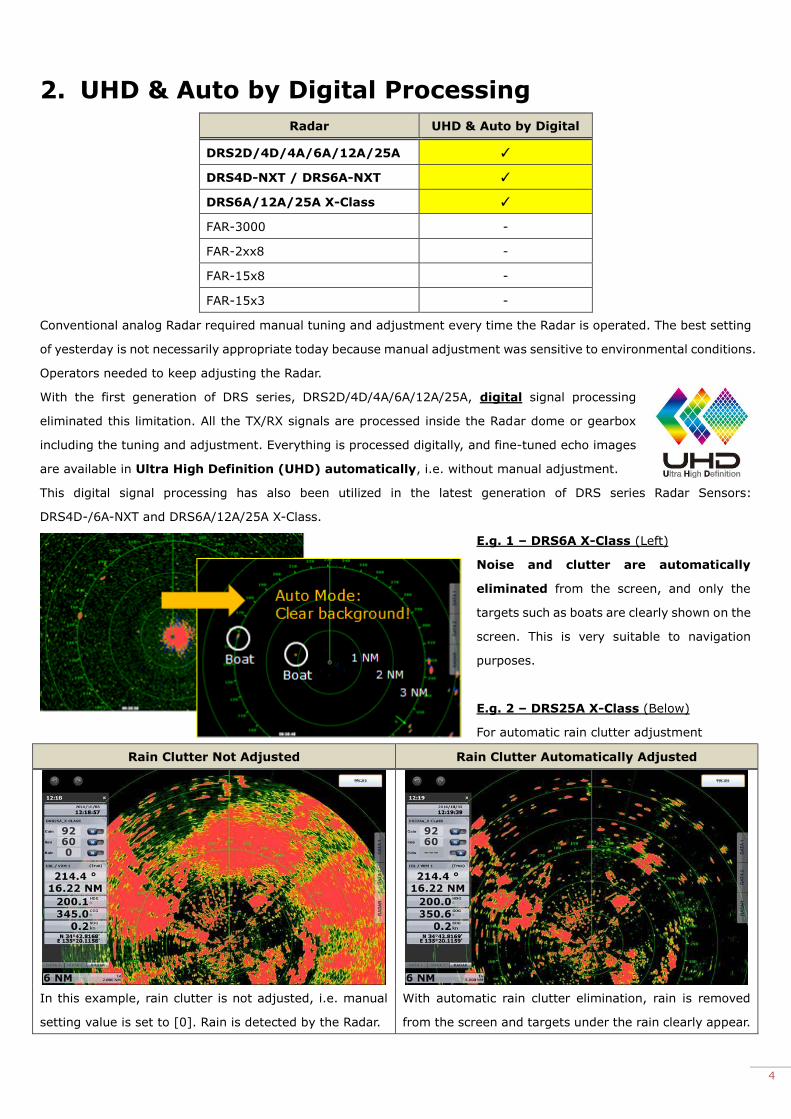
E.g. 2 – DRS25A X-Class (Below)
For automatic rain clutter adjustment
Rain Clutter Not Adjusted Rain Clutter Automatically Adjusted
In this example, rain clutter is not adjusted, i.e. manual
setting value is set to [0]. Rain is detected by the Radar.
With automatic rain clutter elimination, rain is removed
from the screen and targets under the rain clearly appear.
5
3. RezBoost™
Radar RezBoost™
DRS2D/4D/4A/6A/12A/25A -
DRS4D-NXT / DRS6A-NXT ✓
DRS6A/12A/25A X-Class -
FAR-3000 -
FAR-2xx8 -
FAR-15x8 -
FAR-15x3 -
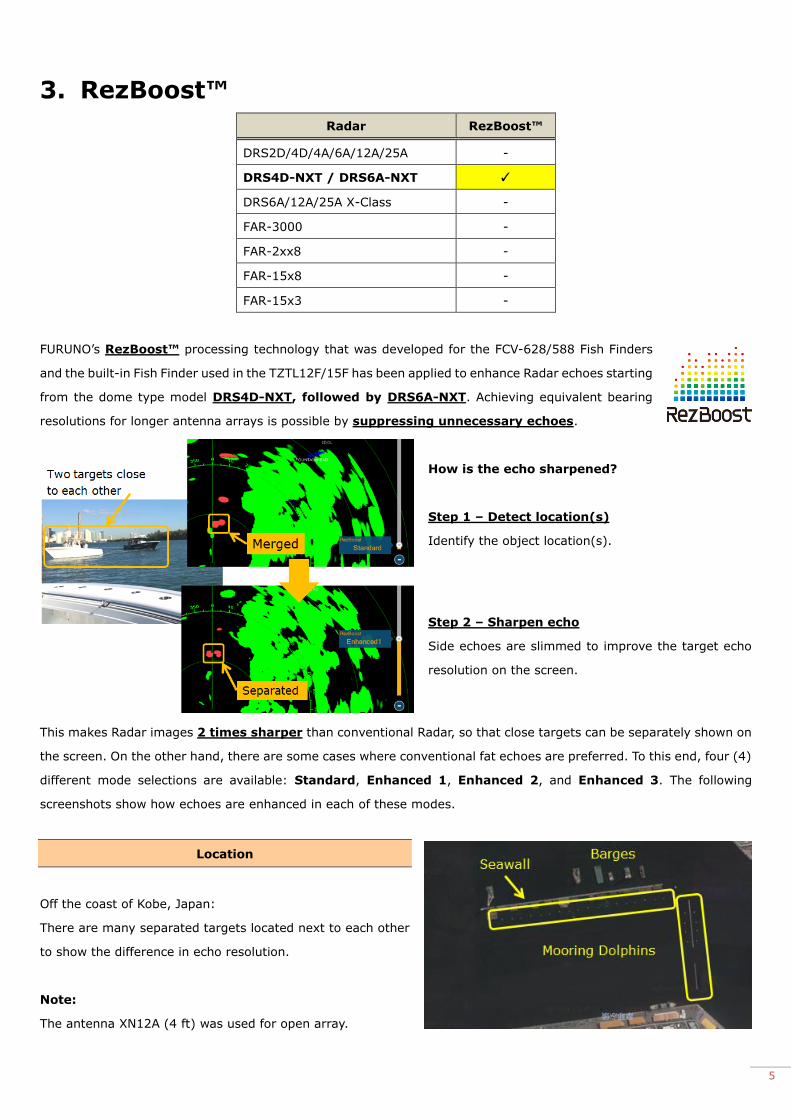
FURUNO’s RezBoost™ processing technology that was developed for the FCV-628/588 Fish Finders
and the built-in Fish Finder used in the TZTL12F/15F has been applied to enhance Radar echoes starting
from the dome type model DRS4D-NXT, followed by DRS6A-NXT. Achieving equivalent bearing
resolutions for longer antenna arrays is possible by suppressing unnecessary echoes.
How is the echo sharpened?
Step 1 – Detect location(s)
Identify the object location(s).
Step 2 – Sharpen echo
Side echoes are slimmed to improve the target echo
resolution on the screen.
This makes Radar images 2 times sharper than conventional Radar, so that close targets can be separately shown on
the screen. On the other hand, there are some cases where conventional fat echoes are preferred. To this end, four (4)
different mode selections are available: Standard, Enhanced 1, Enhanced 2, and Enhanced 3. The following
screenshots show how echoes are enhanced in each of these modes.
Location
Off the coast of Kobe, Japan:
There are many separated targets located next to each other
to show the difference in echo resolution.
Note:
The antenna XN12A (4 ft) was used for open array.
6
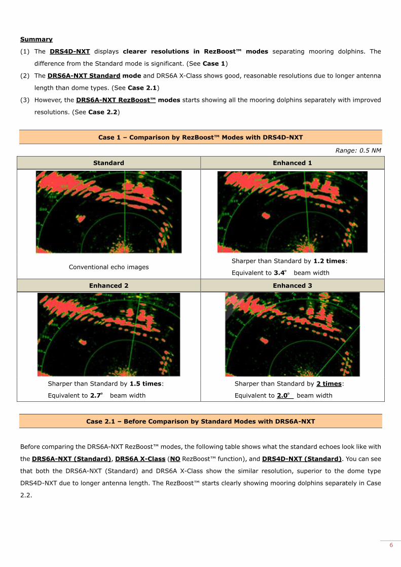
Summary
(1) The DRS4D-NXT displays clearer resolutions in RezBoost™ modes separating mooring dolphins. The
difference from the Standard mode is significant. (See Case 1)
(2) The DRS6A-NXT Standard mode and DRS6A X-Class shows good, reasonable resolutions due to longer antenna
length than dome types. (See Case 2.1)
(3) However, the DRS6A-NXT RezBoost™ modes starts showing all the mooring dolphins separately with improved
resolutions. (See Case 2.2)
Case 1 – Comparison by RezBoost™ Modes with DRS4D-NXT
Range: 0.5 NM
Standard Enhanced 1
Conventional echo images Sharper than Standard by 1.2 times:
Equivalent to 3.4° beam width
Enhanced 2 Enhanced 3
Sharper than Standard by 1.5 times:
Equivalent to 2.7° beam width
Sharper than Standard by 2 times:
Equivalent to 2.0° beam width
Case 2.1 – Before Comparison by Standard Modes with DRS6A-NXT
Before comparing the DRS6A-NXT RezBoost™ modes, the following table shows what the standard echoes look like with
the DRS6A-NXT (Standard), DRS6A X-Class (NO RezBoost™ function), and DRS4D-NXT (Standard). You can see
that both the DRS6A-NXT (Standard) and DRS6A X-Class show the similar resolution, superior to the dome type
DRS4D-NXT due to longer antenna length. The RezBoost™ starts clearly showing mooring dolphins separately in Case
2.2.

7
Range: 0.5 NM
DRS6A-NXT (Standard) DRS6A X-Class DRS4D-NXT (Standard)
Case 2.2 – Comparison by RezBoost™ Modes with DRS6A-NXT
Now, the RezBoost™ modes of DRS6A-NXT are compared. You can see the resolutions gradually improve.
Range: 0.5 NM
Standard Enhanced 1
Conventional echo images Sharper than Standard by 1.2 times:
Dolphins at top start showing good separation.
Enhanced 2 Enhanced 3
Sharper than Standard by 1.5 times:
Dolphins at right start showing good separation.
Sharper than Standard by 2 times:
Dolphins are separated more sharply.
Note:
When RezBoost™ is set to higher value such as [Enhanced 3], echoes from thin targets such as seawalls may look
partially interrupted while sharpening the echoes too highly. Make sure to find the most appropriate setting depending
on the conditions.

8
4. Target Analyzer by Doppler and Analog
Radar Target Analyzer by Doppler Target Analyzer by Analog
DRS2D/4D/4A/6A/12A/25A - -
DRS4D-NXT / DRS6A-NXT ✓ -
DRS6A/12A/25A X-Class - -
FAR-3000 - -
FAR-2xx8 - ✓
FAR-15x8 - ✓
FAR-15x3 - ✓
4.1. Target Analyzer by Doppler – DRS4D-NXT and DRS6A-NXT
The Target Analyzer feature allows you to easily
identify moving or important targets with two (2)
helpful modes. Approaching (moving) targets, rain, and
other targets are color coded to make identification
Target Mode Rain Mode
Approaching targets: RED
Others : GREEN
Approaching targets: RED
Rain : BLUE
Others : GREEN
easier, as outlined in the tables at right. This function is achieved by instantly identify target’s speed with Doppler signal
processing. A demonstration of the Target Analyzer’s function is shown below, showing two (2) moving targets in RED.
Target Analyzer (Target Mode) – ON Target Analyzer - OFF
9
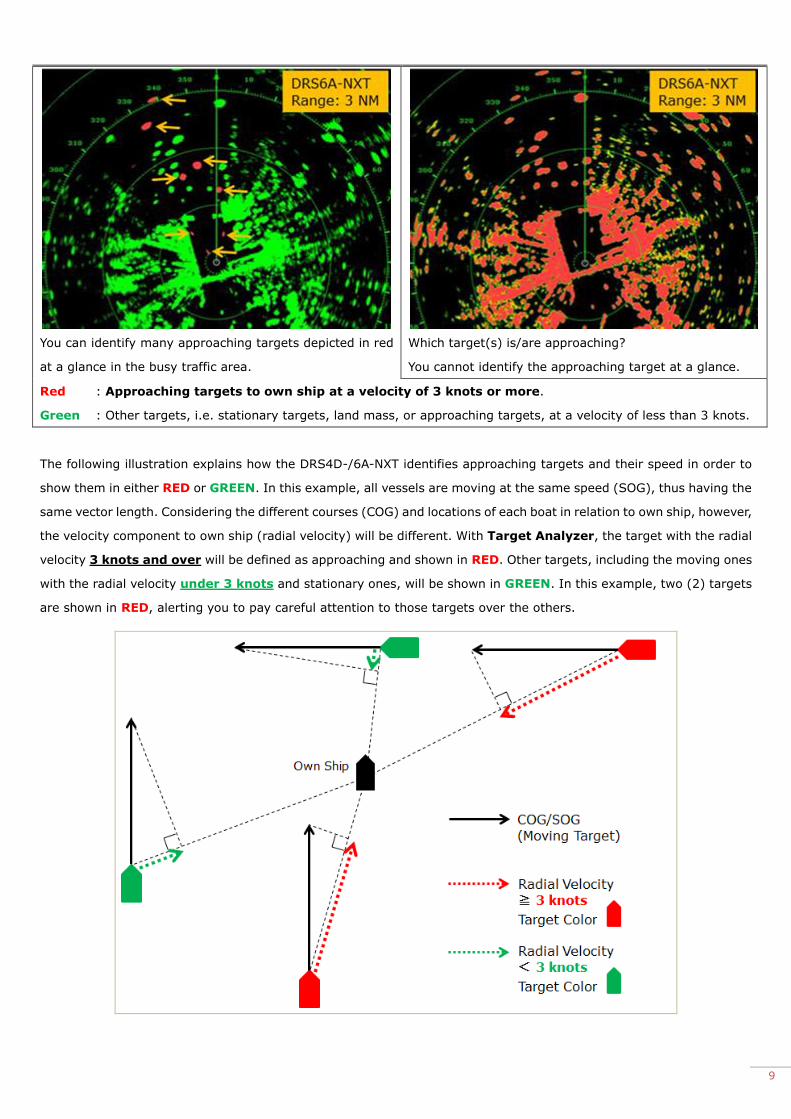
You can identify many approaching targets depicted in red
at a glance in the busy traffic area.
Which target(s) is/are approaching?
You cannot identify the approaching target at a glance.
Red : Approaching targets to own ship at a velocity of 3 knots or more.
Green : Other targets, i.e. stationary targets, land mass, or approaching targets, at a velocity of less than 3 knots.
The following illustration explains how the DRS4D-/6A-NXT identifies approaching targets and their speed in order to
show them in either RED or GREEN. In this example, all vessels are moving at the same speed (SOG), thus having the
same vector length. Considering the different courses (COG) and locations of each boat in relation to own ship, however,
the velocity component to own ship (radial velocity) will be different. With Target Analyzer, the target with the radial
velocity 3 knots and over will be defined as approaching and shown in RED. Other targets, including the moving ones
with the radial velocity under 3 knots and stationary ones, will be shown in GREEN. In this example, two (2) targets
are shown in RED, alerting you to pay careful attention to those targets over the others.

10
Note on Target Speed Limitation
A target with the radial velocity over 50 knots (approx.) may be shown in GREEN rather RED.
Tips – Chasing Targets
Target Analyzer works when you follow boats from behind. As shown in the examples below, the target with the velocity
component 3 knots and over will be defined as approaching and shown in RED. In the following example, own ship is
chasing three (3) vessels.
RED and GREEN dotted arrows show the
difference between the speed of own ship
and the other targets.
Target Color Descriptions
(1) GREEN Own ship is moving slower than this target.
(2) GREEN Own ship is moving slightly faster than this target, thus the velocity
component to own ship is under 3 knots.
(3) RED Own ship is moving much faster than this target, thus the velocity
component to own ship is over 3 knots.
Advanced Operation – Rain Mode
Unique Doppler signal processing offers another benefit: The Rain
Mode is the other mode of Target Analyzer that differentiates rain
and targets in colors. As shown in the example at right, it is useful to
identify approaching targets (RED) under the rain (BLUE).
Target Analyzer – Rain Mode: ON / Echo Trail: OFF
Auto Mode Target Analyzer – Rain Mode

11
4.2. Target Analyzer by Analog – FAR-15xx and FAR-2xx8 (Non-IMO Mode)
Overview
The FAR-15x3, FAR-15x8 (Non-IMO mode), and
FAR-2xx8 (Non-IMO mode) achieve the Target
Analyzer feature by utilizing advanced image
processing inside the powerful processor.
While the Target Analyzer on the DRS4D-/6A-NXT offers
the simple color variation and runs on Auto mode (Auto
Gain/Sea/Rain) to help immediately focus on the
approaching target, the FAR-series models are
customized for more professional use with more
color variations.
Targets are classified into five (5) categories with different colors, which will make it easier for operators to
concentrate on watching and monitoring all of the targets around the boat carefully. A variety of color types
on the screen will also aid an operator to make appropriate adjustments, because the operator can immediately find the
type of targets to be focused on at a glance.
Target Type Target Color (different by presentation mode)
Single-Color Mode Multi-Color Mode
Moving target
(Approaching) Magenta White
Moving target
(NOT approaching) Red Magenta
Stationary target Defined by user such as Yellow
Sea Dark green
(incremental color variation)
Rain Gray
(incremental color variation)
Note:
The Target Analyzer function is available on Non-IMO operation only, i.e. FAR-2xx8 (Non-IMO), FAR-15x8 (Non-IMO
mode), and FAR-15x3.The FAR-2xx8 and FAR-15x8 (IMO mode) are NOT allowed to have multiple color variations by
regulation.

12
Defining Approaching Targets
Basic Process
The Radar checks the motion of targets shown on the screen by sampling targets for 6 times of scan to define the moving
targets and others, then it colors them according to the classified target types.
Moving or Not
Consistently moving targets for 6 scans are regarded as moving.
Approaching or Not
If the newer echo is located relatively closer to Own Ship than the older echo, it becomes a candidate for an approaching
target. However, only targets expected to crash to Own Ship will be regarded as approaching. If the target crosses
in front of Own Ship but very far beyond, it will not be regarded as approaching, but just moving.
Scenes from Navigation
Here are some screens from navigation with Target Analyzer. In this example, the echo is in the single YELLOW color
mode: [BRILLIANCE (1/2)] – [1 ECHO COLOR] – [YEL] (yellow).
(1) Right after the Target Analyzer
is turned on, all the echoes are
still in yellow.
(2) After several antenna sweeps,
moving (not approaching)
targets turned into RED.

13
(3) In the area with heavy marine traffic, the color of approaching targets changed to MAGENTA.
(4) The following scene has approaching targets in MAGENTA, moving targets (not approaching) in RED, and
stationary targets in YELLOW.
14
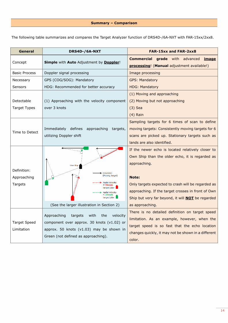
Summary – Comparison
The following table summarizes and compares the Target Analyzer function of DRS4D-/6A-NXT with FAR-15xx/2xx8.
General DRS4D-/6A-NXT FAR-15xx and FAR-2xx8
Concept Simple with Auto Adjustment by Doppler! Commercial grade with advanced image
processing! (Manual adjustment available!)
Basic Process Doppler signal processing Image processing
Necessary
Sensors
GPS (COG/SOG): Mandatory
HDG: Recommended for better accuracy
GPS: Mandatory
HDG: Mandatory
Detectable
Target Types
(1) Approaching with the velocity component
over 3 knots
(1) Moving and approaching
(2) Moving but not approaching
(3) Sea
(4) Rain
Time to Detect Immediately defines approaching targets,
utilizing Doppler shift
Sampling targets for 6 times of scan to define
moving targets: Consistently moving targets for 6
scans are picked up. Stationary targets such as
lands are also identified.
Definition:
Approaching
Targets
(See the larger illustration in Section 2)
If the newer echo is located relatively closer to
Own Ship than the older echo, it is regarded as
approaching.
Note:
Only targets expected to crash will be regarded as
approaching. If the target crosses in front of Own
Ship but very far beyond, it will NOT be regarded
as approaching.
Target Speed
Limitation
Approaching targets with the velocity
component over approx. 30 knots (v1.02) or
approx. 50 knots (v1.03) may be shown in
Green (not defined as approaching).
There is no detailed definition on target speed
limitation. As an example, however, when the
target speed is so fast that the echo location
changes quickly, it may not be shown in a different
color.

15
Presentation DRS4D-/6A-NXT FAR-15xx and FAR-2xx8
Target Color:
Moving and
Approaching
Red Magenta (single-color presentation mode)
or White (multi-color presentation mode)
Target Color:
Moving but NOT
Approaching
Green Red (single-color presentation mode)
or Magenta (multi-color presentation mode)
Target Color:
Stationary Green Defined by user such as Yellow
Target Color:
Sea Green Dark green (incremental color variation)
Target Color:
Rain
Green (Target Mode)
Blue (Rain Mode) Gray (incremental color variation)
Comparison DRS4D-/6A-NXT FAR-15xx and FAR-2xx8
Advantage
(1) Just a single scan to define approaching
targets
(2) Rain mode also available
(3) Consistent performance in both short and
long range scales
(1) Achieved even with magnetron (no Doppler)
(2) Rain and target are shown in different colors
(3) Lower risk of misjudging of stationary and
moving targets thanks to longer sampling time (6
scans)
Limitation
(1) Speed limitation of approaching targets:
The approaching target velocity component
should be over 3 knots and under approx. 30
knots (v1.02) or 50 knots (v1.03)
(1) Longer time to analyze target (6 scans)
(2) In long range scales, it may take longer to
define moving targets because target echoes can
be small with shorter pixel motions on the screen.
16
5. ACE – Automatic Clutter Elimination
Radar ACE
DRS2D/4D/4A/6A/12A/25A -
DRS4D-NXT / DRS6A-NXT -
DRS6A/12A/25A X-Class -
FAR-3000 ✓
FAR-2xx8 ✓
FAR-15x8 ✓
FAR-15x3 ✓
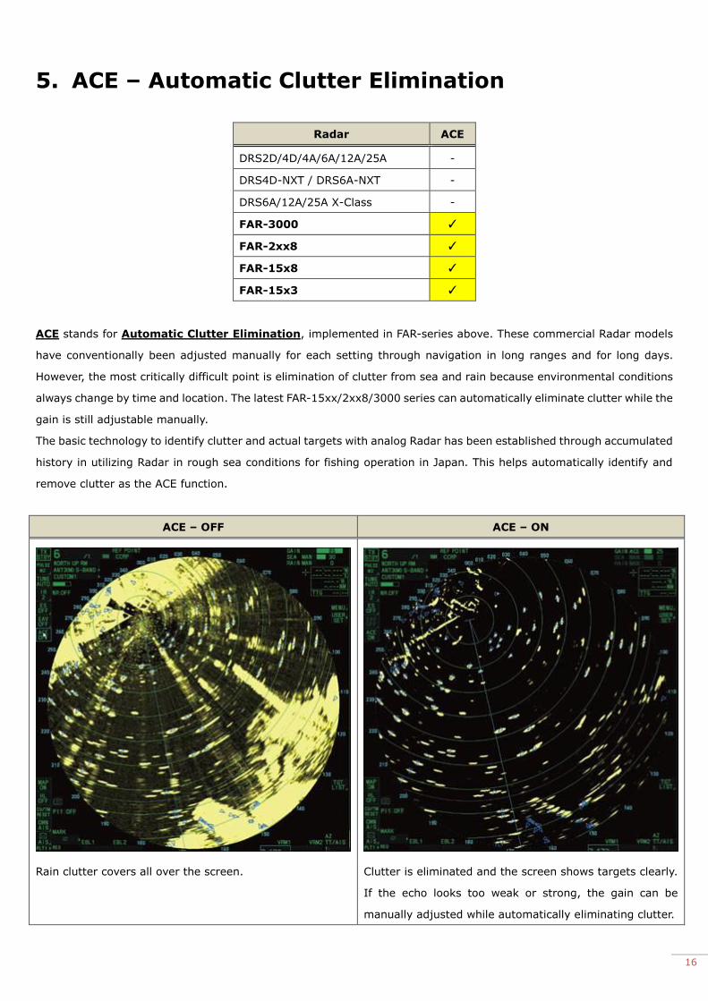
ACE stands for Automatic Clutter Elimination, implemented in FAR-series above. These commercial Radar models
have conventionally been adjusted manually for each setting through navigation in long ranges and for long days.
However, the most critically difficult point is elimination of clutter from sea and rain because environmental conditions
always change by time and location. The latest FAR-15xx/2xx8/3000 series can automatically eliminate clutter while the
gain is still adjustable manually.
The basic technology to identify clutter and actual targets with analog Radar has been established through accumulated
history in utilizing Radar in rough sea conditions for fishing operation in Japan. This helps automatically identify and
remove clutter as the ACE function.
ACE – OFF ACE – ON
Rain clutter covers all over the screen. Clutter is eliminated and the screen shows targets clearly.
If the echo looks too weak or strong, the gain can be
manually adjusted while automatically eliminating clutter.
17
6. Sensitive Receiver & Long Pulse TX
Radar Sensitive Receiver & Long Pulse TX
DRS2D/4D/4A/6A/12A/25A -
DRS4D-NXT / DRS6A-NXT -
DRS6A/12A/25A X-Class ✓ (Max. 1.2 μs)
FAR-3000 ✓ (Max. 1.2 μs)
FAR-2xx8 ✓ (Max. 1.2 μs)
FAR-15x8 ✓ (Max. 1.2 μs)
FAR-15x3 - (Max. 0.8 μs)
6.1. Catching Small Targets in Short Range
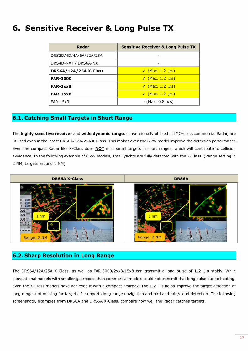
The highly sensitive receiver and wide dynamic range, conventionally utilized in IMO-class commercial Radar, are
utilized even in the latest DRS6A/12A/25A X-Class. This makes even the 6 kW model improve the detection performance.
Even the compact Radar like X-Class does NOT miss small targets in short ranges, which will contribute to collision
avoidance. In the following example of 6 kW models, small yachts are fully detected with the X-Class. (Range setting in
2 NM, targets around 1 NM)
DRS6A X-Class DRS6A
6.2. Sharp Resolution in Long Range
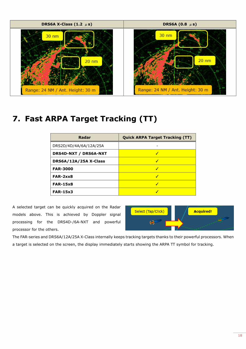
The DRS6A/12A/25A X-Class, as well as FAR-3000/2xx8/15x8 can transmit a long pulse of 1.2 μs stably. While
conventional models with smaller gearboxes than commercial models could not transmit that long pulse due to heating,
even the X-Class models have achieved it with a compact gearbox. The 1.2 μs helps improve the target detection at
long range, not missing far targets. It supports long range navigation and bird and rain/cloud detection. The following
screenshots, examples from DRS6A and DRS6A X-Class, compare how well the Radar catches targets.
18
DRS6A X-Class (1.2 μs) DRS6A (0.8 μs)
7. Fast ARPA Target Tracking (TT)
Radar Quick ARPA Target Tracking (TT)
DRS2D/4D/4A/6A/12A/25A -
DRS4D-NXT / DRS6A-NXT ✓
DRS6A/12A/25A X-Class ✓
FAR-3000 ✓
FAR-2xx8 ✓
FAR-15x8 ✓
FAR-15x3 ✓
A selected target can be quickly acquired on the Radar
models above. This is achieved by Doppler signal
processing for the DRS4D-/6A-NXT and powerful
processor for the others.
The FAR-series and DRS6A/12A/25A X-Class internally keeps tracking targets thanks to their powerful processors. When
a target is selected on the screen, the display immediately starts showing the ARPA TT symbol for tracking.

19
8. Auto Acquire by Doppler
Radar Auto Acquire by Doppler
DRS2D/4D/4A/6A/12A/25A -
DRS4D-NXT / DRS6A-NXT ✓
DRS6A/12A/25A X-Class -
FAR-3000 -
FAR-2xx8 -
FAR-15x8 -
FAR-15x3 -
With the conventional ARPA Target Tracking feature, target acquisition and tracking were done automatically, but
only within a set guard zone. The DRS4D-/6A-NXT, however, is different. Thanks to Doppler signal processing, targets
in any direction within a 3 NM range can be automatically acquired and tracked. The table below compares the
differences between the new Auto Acquire by Doppler and conventional target tracking.
Items DRS4D-/6A-NXT Conventional Models
Auto Acquisition in Guard Zone Available Available
Auto Acquire by Doppler Acquiring approaching targets within 3 NM
Velocity component: Over 3 knots as shown NOT available
In the example at right, targets within 3 NM are acquired and tracked
automatically. Their velocity components are over 3 knots. The vector
lines from the ARPA Target Tracking symbols show the directions in
which the targets are moving. In addition to echo trails, the Auto Acquire
by Doppler feature allows the operator to see the approaching target’s
direction in relation to own ship.
Note:
This feature uses RED and GREEN target symbols. Targets that have
triggered the CPA/TCPA alarm are shown in RED symbols much like conventional ARPA Target Tracking.

20
Advanced Operation – Combination with Target Analyzer
Combination of Target Analyzer with Auto Acquire by Doppler
enables the ability to show approaching targets in RED with the
vector of automatically tracked targets, so that the moving direction
of surrounding targets can be more easily identified. The vector
length representing the speed element also helps to identify targets
approaching fast. In the example at right, two (2) targets are heading
to own ship, while the target at left is expected to go across behind
own ship. The example at right shows that two (2) targets are approaching.
You can see that the target with the longer vector is approaching faster.
In addition, with the CPA/TCPA alarm set to on, acquired targets expected to
approach within a preset range are shown in red symbols to alert you, as
shown in the example at left.
Note on Target Speed Limitation
The target with the velocity component over 50 knots (approx.) may NOT be automatically acquired.
--- END ---
- All brand and product names are registered trademarks, trademarks or service marks of their respective holders.
Recommended