Users Guide to the Integrated Analog Trunk Measurements CID 132167
Version 1.1
Avaya, Inc. 307 Middletown-Lincroft Rd Lincroft, NJ 07738 http://www.avaya.com

ii

i
Contents
General Information .................................................................................................................1 Introduction................................................................................................................................1
Loss ...........................................................................................................................................2 Noise ........................................................................................................................................2 Crosstalk ..................................................................................................................................3 Local Echo ..............................................................................................................................3
Measurements ...........................................................................................................................5 Measurement considerations..............................................................................................6
Administration of trunks.....................................................................................................6 Gateway Trunks as Test Lines ...........................................................................................7 Measurements Between Gateways ...............................................................................7
CLI.............................................................................................................................................7 Loss...............................................................................................................................................8
Measuring Loss in the Subscriber loop ...............................................................................8 Measuring End to End Loss .............................................................................................10
Compensating for subscriber loop loss............................................................................13 Adjusting Receive Gain ..................................................................................................13 Adjusting Transmit Gain ..................................................................................................13
Noise ..........................................................................................................................................14 Measuring Noise on the Subscriber Loop........................................................................14
Measuring End to End Noise ..........................................................................................16 Crosstalk ....................................................................................................................................19
Measuring Crosstalk on the Subscriber Loop..................................................................19 Local Echo................................................................................................................................24
Hybrid Balance ....................................................................................................................24 Examples ...........................................................................................................................24 Measuring Hybrid Balance on the Subscriber loop ...................................................24 Measuring End to End hybrid balance ........................................................................26
Finding the Optimum Hybrid Balance .............................................................................28 Match on Subscriber loop..............................................................................................29 Match on an end to end connection .........................................................................31
Using the Optimum Hybrid Balance.....................................................................................33 CLI reference ...........................................................................................................................34 Errors...........................................................................................................................................34

1
General Information
This document applies to the following gateway analog circuits. G250 Analog hardware vintage 5 and greater G250 DS1 hardware vintage 1 and greater G250 BRI hardware vintage 2 and greater G350 hardware vintage 6 and greater IG550 and all analog TIMs: TIM508 TIM514 TIM516 TIM518 Analog media modules: MM711 hardware vintage 30 and greater MM714 hardware vintage 10 and greater MM716 all hardware vintages Gateway firmware (G250, G350, G450, G700, IG550) must be 28.16.0 or greater. Media Module firmware must be vintage 91 or greater.
Introduction
Most of today’s Voice Over Internet Protocol (VOIP) networks include gateways that convert analog signals from the traditional telephone network interfaces to VOIP. These traditional telephone interfaces provide access the Public Switched Telephone Network (PSTN) via analog trunks. Voice quality within the VOIP network depends on good quality audio signals from the gateway analog trunks and the PSTN. Audio quality in the PSTN and analog trunks basically consists of the parameters; loudness, noise, echo and distortion. Throughout the PSTN, these parameters are engineered to meet grade of service objectives. However this is not always the case for the last leg in the telephone network, the analog connection between the Central Office and the customer’s equipment known as the subscriber loop. This document is intended to guide the user in measuring impairments, and administering custom changes to transmission parameters on the media gateway analog trunks.
2
Loss
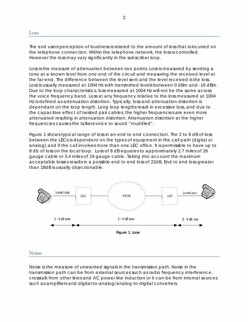
The end users perception of loudness is related to the amount of loss that is incurred on the telephone connection. Within the telephone network, the loss is controlled. However the loss may vary significantly in the subscriber loop. Loss is the measure of attenuation between two points. Loss is measured by sending a tone at a known level from one end of the circuit and measuring the received level at the far-end. The difference between the level sent and the level received is the loss. Loss is usually measured at 1004 Hz with transmitted levels between 0 dBm and -16 dBm. Due to the loop characteristics, loss measured at 1004 Hz will not be the same across the voice frequency band. Loss at any frequency relative to the loss measured at 1004 Hz is defined as attenuation distortion. Typically, loss and attenuation distortion is dependant on the loop length. Long loop lengths result in excessive loss, and due to the capacitive effect of twisted pair cables, the higher frequencies are even more attenuated resulting in attenuation distortion. Attenuation distortion at the higher frequencies causes the talkers voice to sound “muddled”. Figure 1 shows typical range of loss in an end to end connection. The 2 to 6 dB of loss between the LECs is dependent on the types of equipment in the call path (digital or analog) and if the call involves more than one LEC office. It is permissible to have up to 8 db of loss on the local loop. Loss of 8 dB equates to approximately 2.7 miles of 26 gauge cable or 3.4 miles of 24 gauge cable. Taking into account the maximum acceptable losses results in a possible end to end loss of 22dB. End to end loss greater than 18dB is usually objectionable.
Figure 1, Loss
Noise
Noise is the measure of unwanted signals in the transmission path. Noise in the transmission path can be from external sources such as radio frequency interference, crosstalk from other lines and AC power line induction or it can be from internal sources such as amplifiers and digital-to-analog/analog-to-digital converters.

3
Noise on telephone circuits is measured as a power level over the voice frequency band using weighting filters. The weighting filters used are 3 kHz flat and, C-Message for North America or psophometric elsewhere. C-Message and psophometric weighting were developed years ago to simulate the frequency response the 500 type telephone set and have significant low frequency roll-off. The frequency response of today’s circuits match more closely with the 3 kHz flat weighting. The reference noise level, 0 dBrn, is one picowatt. 0 dBrn corresponds to -90 dBm. It is desirable to have the noise level less than 20 dbrn. However noise levels less than 30 dBrn are acceptable and noise levels greater than 40 dbrn are usually objectionable.
Crosstalk
Crosstalk is the unwanted coupling of voice signals between any two voice paths. Crosstalk coupling is measured by sending a tone at a known level from one voice path, the disturbing path, and measuring the tone level on another voice path, the disturbed path. It is desirable to have the crosstalk coupling less than -80 db. However crosstalk coupling of less than -70 dB is acceptable and crosstalk coupling greater than -65 db is usually objectionable.
Local Echo
Local echo is caused by signal reflections at impedance discontinuities, which occur at the 2-wire to 4-wire interfaces on the analog port circuits and where impedance mismatches occur on the two wire loops. Two forms of echo exist: talker echo and listener echo. Talker echo is the reflection of the talker’s voice back to the talker. This form of echo is always present and is known as sidetone. Sidetone is usually not objectionable unless it is excessive. Also, if there is enough delay between the talker’s spoken words and the time the sidetone is heard, the talker will find it objectionable. Listener echo occurs when the signal passes through two reflection points and is added to the transmitted speech. The feedback can cause a talkers voice to sound “hollow” to the listener. Echo is controlled within the VOIP network primarily with echo cancellers. The echo cancellers do an excellent job in eliminating objectionable echo. However, echo cancellers require some time to learn about the echo. During this training time some echo may be heard. Also, at times, the echo may be too loud for the echo canceller to handle. Echo control is always best managed at or as close as possible to its source. For the local echo on the analog trunks, this would be at the 2 to 4 wire hybrid. The hybrid, shown in Figure 3, separates the send and receive signals from the common two-way telephone pair. For the hybrid to work properly, it must be balanced against the loop impedance of the line it is connected to. If the loop and the balance impedances are identical, there will be no part of the send signal in the receive path. The balance impedance is specific for individual countries. For the United States, the standard balance impedance is either set to 600 ohms (typically used for trunk to trunk

4
connections) or to a complex impedance that represents the average loop impedance. Since it is most likely that the actual loop impedance does not match the balance impedance, some of the send signal will appear in the receive path. The measure of amount of the send signal in the receive path, referenced to the send signal is known as trans-hybrid loss (THL). The loss is not necessarily the same across the voice frequency band so THL is measured verses frequency. Echo Return Loss (ERL) is an average over the voice band.
Trunk/Tel Set
Trunk/Tel SetHybrid Hybrid
Talker Path Echo
Listener Path Echo
Figure 2, Echo Path

5
Figure 3, Hybrid
The greater the ERL number the less likelihood of objectionable echo. Also the THL should be as flat as possible over the voice band. THL at any frequency should not be negative.
Measurements
DSP features in the new analog port circuitry make it possible to measure loss, noise, crosstalk, and trans-hybrid loss and to implement customized changes to account for some of these conditions. The impairments discussed in this document are concerned with the analog trunk circuits and the local loop connecting the trunk circuit to the LEC. Measuring the local loop is typically accomplished using a Remote Office Test Line (ROTL) provided by the LEC. In general, trunk lines in a telephone network are tested automatically. The trunk lines to be tested are chosen under the control of a computerized system known as Centralized Automatic Reporting on Trunks (CAROT). In addition to choosing the trunks to be tested, the CAROT system receives and analyzes data representing test results from particular trunks.
Tests can also be carried out on with external test equipment connected to the subscriber loop. The external test equipment, such as a SAGE Instruments Communications Test Set, can access the CAROT test lines and perform transmission measurements.
Test Lines
6
The measurements performed by the analog trunk ports in the gateway are based on some of the more common CAROT test lines; TEST 100, TEST 102 and TEST 105.
The TEST 100 line answers an incoming call, sends a 1004 Hz tone at 0 dBm for 5.5 seconds then remains quiet until it is disconnected. This test line is also known as the quiet termination. The TEST 102 line answers an incoming call, sends a 1004 Hz tone at 0 dBm for 9 seconds then remains quiet for 1 second. The line repeats the 1004Hz/quiet sequence until disconnected. This test line is also known as the milliwatt test line. The TEST 105 line answers an incoming call then: • sends a 1004 Hz tone at -16 dBm for 9 seconds • remains quiet for 1 second • sends a 404 Hz tone at -16 dBm for 9 seconds • remains quiet for 1 second • sends a 2804 Hz tone at -16 dBm for 9 seconds • remains quiet for 30 second • sends a 2225 Hz tone (progress tone) at -16 dBm for half a second • forces disconnect
Since the primary purpose of the integrated testing is to measure the subscriber loop, the test lines if possible should be the ones provided by the local switching office. Test lines are accessed by dialing a specific number prescribed by the local switching office.
Also, as part of the integrated testing, trunk ports can be configured to act as the test line.
Measurement considerations
Administration of trunks
Ports should be administered then taken out of service. If an analog port has not been previously administered and placed into service, measurements associated with the port may not be accurate and may even fail. Until the port is administered, there is no way to know anything about the specific trunk such as whether it is DID, Ground Start, etc. Since all measurements are performed at the gateway level, the CM has no indication that the ports may be in use by the gateway during a measurement. Therefore to prevent confusion the ports involved in a measurement should be taken out of service. In the event the port is not taken out of service, any action by the CM associated with the ports involved in a measurement will cause the measurement to abort. Also, the gateway must be registered with CM. The measurements use the gateway DTMF tones. If the gateway is not registered, the gateway DTMF tones are not available.
7
Gateway Trunks as Test Lines The analog trunks can be set up as a TEST 100, Test 102, or TEST 105 line only and external test equipment can be used to make measurements. This is done by launching a test profile with only the responder port and type fields filled in the profile. If this type of profile is launched, it will run indefinitely until the profile is cancelled. This allows multiple tests, at the user’s discretion, to be performed on the trunk using the external equipment.
Measurements between Gateways The user can make measurements between gateways by configuring TEST 100/102 lines on one gateway and launching a test profile on the other gateway.
CLI
CLI examples assume that the user is working with a new profile ID, or has executed the clear profile command on a previously created profile. CLI examples also assume that the user has already entered the analog-test context before entering any of the CLI commands.

8
Loss
Measuring Loss in the Subscriber loop
Far End is Local Switching Office
This method is the most accurate way for measuring subscriber loop loss. It involves dialing into the local switching office’s TEST102 line. Measuring the subscriber loop when the far end is the local switching office can only be made on loop-start and ground start trunks since the measurement requires originating a call from the port under test.
For this measurement, create a test profile which includes the following:
1. set port to the port under test 2. set test type to loss 3. set destination to the number of the local switching office’s TEST102 line
Create the profile G350-005(super-analog-test)# profile measure1 G350-005(super-analog-test/profile measure1)# set port v401 G350-005(super-analog-test/profile measure1)# set type receive-loss G350-005(super-analog-test/profile measure1)# set destination 7771234
Check the profile G350-005(super-analog-test/profile measure1)# show Id Port State Type Destination ---------- ---- -------------------- ------------- -------------- measure1 v401 idle receive-loss 7771234 Resp. Resp. type X. Port X. Destination X. Resp. X. Resp. type ----- ---------- ------- -------------- -------- ------------- - - - - - - Done! G350-005(super-analog-test/profile measure1)# exit
Run the profile G350-005(super-analog-test)# launch measure1
Get the results G350-005(super-analog-test)# profile measure1 G350-005(super-analog-test/profile measure1)# show result Loss: +4.43 dB
What takes place during this measurement.

9
After the test is launched: • Port v401 goes off-hook , • Waits for dial tone • Dials 7771234 using DTMF signaling • Waits for 1000 Hz tone from local switching office • Makes the measurement
Far End is Another Port in the Gateway
This method actually measures the combined loss of the two subscriber loops involved as well as any loss inserted by the local switching office for the end-to-end connection. When making this type of measurement, the responder port can be any trunk type (loop-start, ground-start, DID). However the other port under test can only be a loop-start or ground start trunk since the measurement requires originating a call from this port.
For this measurement, create a test profile which includes the following:
1. set port to one of the ports under test 2. set responder port to the other port under test 3. set responder type to 102 4. set test type to loss 5. set destination to the telephone number of the line connected to the port used
as the TEST 102 line.
Create the profile G350-005(super-analog-test)# profile measure1 G350-005(super-analog-test/profile measure1)# set port v401 G350-005(super-analog-test/profile measure1)# set responder v402 G350-005(super-analog-test/profile measure1)# set responder-type 102 G350-005(super-analog-test/profile measure1)# set type receive-loss G350-005(super-analog-test/profile measure1)# set destination 5551234
Check the profile G350-005(super-analog-test/profile measure1)# show Id Port State Type Destination ---------- ---- -------------------- ------------- -------------- measure1 v401 idle receive-loss 5551234 Resp. Resp. type X. Port X. Destination X. Resp. X. Resp. type ----- ---------- ------- -------------- -------- ------------- v402 102 - - - - Done! G350-005(super-analog-test/profile measure1)# exit
Run the profile G350-005(super-analog-test)# launch measure1
Get the results

10
G350-005(super-analog-test)# profile measure1 G350-005(super-analog-test/profile measure1)# show result Loss: +4.43 dB
What takes place during this measurement. After the test is launched: • Port v402 is configured as a TEST102 line • Port v401 goes off-hook • Port v401 waits for dial tone • Port v401 Dial 5551234 using DTMF signaling • Port v401 then waits for 1000 Hz tone from port v402 • Port v402 detects ringing and answers • Port V402 sends 1000Hz 0dBm tone • Port v401 makes the measurement
Measuring End to End Loss
Making the measurement from equipment at the far end
This method actually measures the combined loss of the subscriber loop connected to the port under test, the subscriber loop connected to the test equipment, and any loss inserted by the telephone network for the end-to-end connection. When making this type of measurement, the responder can be any trunk type (loop-start, ground-start, DID). When the only setting in the profile is a responder, the user must cancel the profile after finishing the measurement, since there is no automatic way to know when the user has completed the measurements at the far end.
This method requires that test equipment be connected to the trunk at the far end.
For this measurement, create a test profile which includes the following: 1. set responder port to the port under test 2. set responder type to 102
We then need to launch the profile then execute the loss test from the test equipment at the far end.
Create the profile G350-005(super-analog-test)# profile measure1 G350-005(super-analog-test/profile measure1)# set responder v402 G350-005(super-analog-test/profile measure1)# set responder-type 102 G350-005(super-analog-test/profile measure1)# set type passive
Check the profile G350-005(super-analog-test/profile measure1)# show Id Port State Type Destination

11
---------- ---- -------------------- ------------- -------------- measure1 - idle passive - Resp. Resp. type X. Port X. Destination X. Resp. X. Resp. type ----- ---------- ------- -------------- -------- ------------- v402 102 - - - - Done! G350-005(super-analog-test/profile measure1)# exit
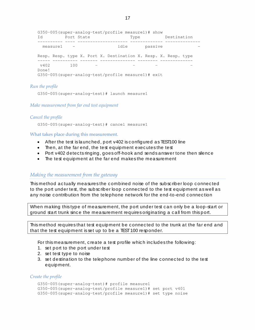
Run the profile G350-005(super-analog-test)# launch measure1
Make measurement from far end test equipment
Cancel the profile G350-005(super-analog-test)# cancel measure1
What takes place during this measurement. • After the test is launched, port v402 is configured as TEST102 line • Then, at the far end, the test equipment executes the test • Port v402 detects ringing, goes off-hook and sends 1000Hz 0 dBm tone • The test equipment makes the measurement
Making the measurement from the gateway
This method actually measures the combined loss of the subscriber loop connected to the port under test, the subscriber loop connected to the test equipment, and any loss inserted by the telephone network for the end-to-end connection. When making this type of measurement, the port under test can only be a loop-start or ground start trunk since the measurement requires originating a call from this port. This method requires that test equipment be connected to the trunk at the far end and that the test equipment is set up to be a TEST 102 responder.
For this measurement, create a test profile which includes the following:
1. set port to the port under test 2. set test type to loss 3. set destination to the telephone number of the line connected to the test
equipment.
Create the profile G350-005(super-analog-test)# profile measure1 G350-005(super-analog-test/profile measure1)# set port v401 G350-005(super-analog-test/profile measure1)# set type receive-loss G350-005(super-analog-test/profile measure1)# set destination 2015551234

12
Check the profile G350-005(super-analog-test/profile measure1)# show Id Port State Type Destination ---------- ---- -------------------- ------------- -------------- measure1 v401 idle receive-loss 2015551234 Resp. Resp. type X. Port X. Destination X. Resp. X. Resp. type ----- ---------- ------- -------------- -------- ------------- - - - - - - Done! G350-005(super-analog-test/profile measure1)# exit
Run the profile G350-005(super-analog-test)# launch measure1
Get the results G350-005(super-analog-test)# profile measure1 G350-005(super-analog-test/profile measure1)# show result Loss: +4.43 dB
What takes place during this measurement. After the test is launched: • Port v401 goes off-hook , • Waits for dial tone • Dials 2015551234 using DTMF signaling • Waits for 1000 Hz tone from far end • The test equipment goes off-hook and sends 1000Hz 0dBm tone • Port v401 makes the measurement
Measuring loss on an established connection
This method actually measures the combined loss of the subscriber loop connected to the port under test, the subscriber loop connected to the test equipment, and any loss inserted by the telephone network for the end-to-end connection. This method requires that test equipment be connected to the trunk at the far end and that the test equipment is sending a 0dbm 1000 Hz tone.
For this measurement, create a test profile which includes the following: 1. set port to the port under test 2. set test type to loss
Create the profile G350-005(super-analog-test)# profile measure1 G350-005(super-analog-test/profile measure1)# set port v401 G350-005(super-analog-test/profile measure1)# set type receive-loss

13
Check the profile G350-005(super-analog-test/profile measure1)# show Id Port State Type Destination ---------- ---- -------------------- ------------- -------------- measure1 v401 idle receive-loss - Resp. Resp. type X. Port X. Destination X. Resp. X. Resp. type ----- ---------- ------- -------------- -------- ------------- - - - - - - Done! G350-005(super-analog-test/profile measure1)# exit
Run the profile G350-005(super-analog-test)# launch measure1
Get the results G350-005(super-analog-test)# profile measure1 G350-005(super-analog-test/profile measure1)# show result Loss: +4.43 dB
What takes place during this measurement. • The test equipment at far end sends 1000Hz 0dBm tone
After the test is launched: • Port v401 makes the measurement
Compensating for subscriber loop loss
Loop loss can be compensated for by adding as much as 3 db of gain and as much as 6 db of loss on each individual analog trunk port in the gateway. This compensation is in the trunk port circuitry and is not part of the loss plan.
Adjusting Receive Gain
Example To add 1.5 db of gain in the receive direction for port 201: G350-005(super-analog-test)# set receive-gain v201 1.5
Adjusting Transmit Gain
Example To add 3 db of loss in the transmit direction for port 201: G350-005(super-analog-test)# set transmit-gain v201 -3

14
Noise
Measuring Noise on the Subscriber Loop
Far End is Local Switching Office
This method is the most accurate way for measuring subscriber loop loss. It involves dialing into the local switching office’s TEST100 line. Measuring the subscriber loop when the far end is the local switching office can only be made on loop-start and ground start trunks since the measurement requires originating a call from the port under test.
For this measurement, create a test profile which includes the following:
1. set port to the port under test 2. set test type to noise 3. set destination to the number of the local switching office’s TEST100 line
Create the profile G350-005(super-analog-test)# profile measure1 G350-005(super-analog-test/profile measure1)# set port v401 G350-005(super-analog-test/profile measure1)# set type noise G350-005(super-analog-test/profile measure1)# set destination 7771234
Check the profile G350-005(super-analog-test/profile measure1)# show Id Port State Type Destination ---------- ---- -------------------- ------------- -------------- measure1 v401 idle noise 7771234 Resp. Resp. type X. Port X. Destination X. Resp. X. Resp. type ----- ---------- ------- -------------- -------- ------------- - - - - - - Done! G350-005(super-analog-test/profile measure1)# exit
Run the profile G350-005(super-analog-test)# launch measure1
Get the results G350-005(super-analog-test)# profile measure1 G350-005(super-analog-test/profile measure1)# show result Noise: +4.56 dBrnC, +8.76 dBrn 3kHz flat
What takes place during this measurement.

15
After the test is launched: • Port v401 goes off-hook , • Waits for dial tone • Dials 7771234 using DTMF signaling • Waits for answer tone from local switching office • Waits for silence from local switching office • Makes the measurement
Far End is Another Port in the Gateway
This method actually measures the combined noise of the two subscriber loops involved as well as any noise contribution from the local switching office for the end-to-end connection.
When making this type of measurement, the responder port can be any trunk type (loop-start, ground-start, DID). However the other port under test can only be a loop-start or ground start trunk since the measurement requires originating a call from this port.
For this measurement, create a test profile which includes the following:
1. set port to one of the ports under test 2. set responder port to the other port under test 3. set responder type to 100 4. set test type to noise 5. set destination to the telephone number of the line connected to the port used
as the TEST 100 line.
Create the profile G350-005(super-analog-test)# profile measure1 G350-005(super-analog-test/profile measure1)# set port v401 G350-005(super-analog-test/profile measure1)# set responder v402 G350-005(super-analog-test/profile measure1)# set responder-type 100 G350-005(super-analog-test/profile measure1)# set type noise G350-005(super-analog-test/profile measure1)# set destination 5551234
Check the profile G350-005(super-analog-test/profile measure1)# show Id Port State Type Destination ---------- ---- -------------------- ------------- -------------- measure1 v401 idle noise 5551234 Resp. Resp. type X. Port X. Destination X. Resp. X. Resp. type ----- ---------- ------- -------------- -------- ------------- v402 100 - - - - Done! G350-005(super-analog-test/profile measure1)# exit
Run the profile G350-005(super-analog-test)# launch measure1

16
Get the results G350-005(super-analog-test)# profile measure1 G350-005(super-analog-test/profile measure1)# show result Noise: +4.56 dBrnC, +8.76 dBrn 3kHz flat
What takes place during this measurement. After the test is launched: • Port v402 is configured as a TEST100 line • Port v401 goes off-hook • Port v401 waits for dial tone • Port v401 Dial 5551234 using DTMF signaling • Port v401 then waits answer tone from port v402 • Port v402 detects ringing and answers • Port V402 sends answer tone then silence • Port v401 waits for silence then makes the measurement
Measuring End to End Noise
Making the measurement from equipment at the far end
This method actually measures the combined noise of the subscriber loop connected to the port under test, the subscriber loop connected to the test equipment as well as any noise contribution from the telephone network for the end-to-end connection When making this type of measurement, the responder can be any trunk type (loop-start, ground-start, DID). When the only setting in the profile is a responder, the user must cancel the profile after finishing the measurement, since there is no automatic way to know when the user has completed the measurements at the far end.
This method requires that test equipment be connected to the trunk at the far end.
1. For this measurement, create a test profile which includes the following: 2. set responder port to the port under test 3. set responder type to 100 We then need to launch the profile then make the noise measurement from the test
equipment at the far end.
Create the profile G350-005(super-analog-test)# profile measure1 G350-005(super-analog-test/profile measure1)# set responder v402 G350-005(super-analog-test/profile measure1)# set responder-type 100 G350-005(super-analog-test/profile measure1)# set type passive
Check the profile
17
G350-005(super-analog-test/profile measure1)# show Id Port State Type Destination ---------- ---- -------------------- ------------- -------------- measure1 - idle passive - Resp. Resp. type X. Port X. Destination X. Resp. X. Resp. type ----- ---------- ------- -------------- -------- ------------- v402 100 - - - - Done! G350-005(super-analog-test/profile measure1)# exit
Run the profile G350-005(super-analog-test)# launch measure1
Make measurement from far end test equipment
Cancel the profile G350-005(super-analog-test)# cancel measure1
What takes place during this measurement. • After the test is launched, port v402 is configured as TEST100 line • Then, at the far end, the test equipment executes the test • Port v402 detects ringing, goes off-hook and sends answer tone then silence • The test equipment at the far end makes the measurement
Making the measurement from the gateway
This method actually measures the combined noise of the subscriber loop connected to the port under test, the subscriber loop connected to the test equipment as well as any noise contribution from the telephone network for the end-to-end connection When making this type of measurement, the port under test can only be a loop-start or ground start trunk since the measurement requires originating a call from this port. This method requires that test equipment be connected to the trunk at the far end and that the test equipment is set up to be a TEST 100 responder.
For this measurement, create a test profile which includes the following: 1. set port to the port under test 2. set test type to noise 3. set destination to the telephone number of the line connected to the test
equipment.
Create the profile G350-005(super-analog-test)# profile measure1 G350-005(super-analog-test/profile measure1)# set port v401 G350-005(super-analog-test/profile measure1)# set type noise

18
G350-005(super-analog-test/profile measure1)# set destination 2015551234
Check the profile G350-005(super-analog-test/profile measure1)# show Id Port State Type Destination ---------- ---- -------------------- ------------- -------------- measure1 v401 idle noise 2015551234 Resp. Resp. type X. Port X. Destination X. Resp. X. Resp. type ----- ---------- ------- -------------- -------- ------------- - - - - - - Done! G350-005(super-analog-test/profile measure1)# exit
Run the profile G350-005(super-analog-test)# launch measure1
Get the results G350-005(super-analog-test)# profile measure1 G350-005(super-analog-test/profile measure1)# show result Noise: +4.56 dBrnC, +8.76 dBrn 3kHz flat
What takes place during this measurement. After the test is launched: • Port v401 goes off-hook , • Waits for dial tone • Dials 2015551234 using DTMF signaling • Waits for answer tone from far end • The test equipment goes off-hook and sends answer tone then silence • Port v401 detects answer tone, waits for silence then makes the measurement
Measuring Noise on an established connection
This method actually measures the combined noise of the local loop connected to the port under test, the local loop connected to the test equipment as well as any noise contribution from the telephone network for the end-to-end connection This method requires that both ends have some type of silent termination (endpoints on hold without music or announcements, endpoints on mute).
For this measurement, create a test profile which includes the following:
1. set port to the port under test 2. set test type to noise
Create the profile G350-005(super-analog-test)# profile measure1 G350-005(super-analog-test/profile measure1)# set port v401 G350-005(super-analog-test/profile measure1)# set type noise

19
Check the profile G350-005(super-analog-test/profile measure1)# show Id Port State Type Destination ---------- ---- -------------------- ------------- -------------- measure1 v401 idle noise - Resp. Resp. type X. Port X. Destination X. Resp. X. Resp. type ----- ---------- ------- -------------- -------- ------------- - - - - - - Done! G350-005(super-analog-test/profile measure1)# exit
Run the profile G350-005(super-analog-test)# launch measure1
Get the results G350-005(super-analog-test)# profile measure1 G350-005(super-analog-test/profile measure1)# show result Noise: +4.56 dBrnC, +8.76 dBrn 3kHz flat
What takes place during this measurement. • Port v401 makes the measurement
Crosstalk
Measuring Crosstalk on the Subscriber Loop
Far End is Local Switching Office
This method is the most accurate way for measuring subscriber loop loss. It involves dialing into the local switching office’s TEST100 line. Measuring the subscriber loop when the far end is the local switching office can only be made on loop-start and ground start trunks since the measurement requires originating a call from the port under test.
For this measurement, create a test profile which includes the following:
1. set port to the port under test 2. set test type to crosstalk 3. set destination to the number of the local switching office’s TEST100 responder 4. set crosstalk port to the other port under test 5. set crosstalk destination to the number of the local switching office’s TEST100
responder
Create the profile

20
G350-005(super-analog-test)# profile measure1 G350-005(super-analog-test/profile measure1)# set port v401 G350-005(super-analog-test/profile measure1)# set type crosstalk G350-005(super-analog-test/profile measure1)# set destination 7771234 G350-005(super-analog-test/profile measure1)# set crosstalk-port v405 G350-005(super-analog-test/profile measure1)# set crosstalk-destination
7771234 G350-005(super-analog-test/profile measure1)# set crosstalk-responder none
Check the profile G350-005(super-analog-test/profile measure1)# show Id Port State Type Destination ---------- ---- -------------------- ------------- -------------- measure1 v401 idle crosstalk 7771234 Resp. Resp. type X. Port X. Destination X. Resp. X. Resp. type ----- ---------- ------- -------------- -------- ------------- - - v405 7771234 - - Done! G350-005(super-analog-test/profile measure1)# exit
Run the profile G350-005(super-analog-test)# launch measure1
Get the results G350-005(super-analog-test)# profile measure1 G350-005(super-analog-test/profile measure1)# show result Crosstalk coupling vs. frequency (frequency in Hz, coupling in dB):
( 400,-88.12) (1200,-99.28) (3000,-76.48)
What takes place during this measurement. After the test is launched: • Port v401 goes off-hook , • Waits for dial tone • Dials 7771234 using DTMF signaling • Waits for answer tone from local switching office • Waits for silence from local switching office • Port v405 goes off-hook , • Waits for dial tone • Dials 7771234 using DTMF signaling • Waits for answer tone from local switching office • Waits for silence from local switching office • Tones are sent on port v401 and measurement is made on v405
Far end is another port in the gateway

21
This method actually measures the combined crosstalk of the subscriber loops involved as well as any crosstalk contribution from the local switching office for the end-to-end connections. When making this type of measurement, the responder can be any trunk type (loop-start, ground-start, DID). However the other port under test can only be a loop-start or ground start trunk since the measurement requires originating a call from this port.
For this measurement we need to create a test profile which includes the following: 1. set port to the port under test 2. set test type to crosstalk 3. set responder port to port x 4. set crosstalk responder port to port y 5. set destination to the responder port’s LOCAL SWITCHING OFFICE telephone
number 6. set crosstalk port to the other port under test 7. set crosstalk destination to the crosstalk responder port’s LOCAL SWITCHING
OFFICE telephone number
Create the profile G350-005(super-analog-test)# profile measure1 G350-005(super-analog-test/profile measure1)# set port v401 G350-005(super-analog-test/profile measure1)# set type crosstalk G350-005(super-analog-test/profile measure1)# set responder v202 G350-005(super-analog-test/profile measure1)# set destination 5551234 G350-005(super-analog-test/profile measure1)# set crosstalk-port v403 G350-005(super-analog-test/profile measure1)# set crosstalk-responder v201 G350-005(super-analog-test/profile measure1)# set crosstalk-destination
5556789
Check the profile G350-005(super-analog-test/profile measure1)# show Id Port State Type Destination ---------- ---- -------------------- ------------- -------------- measure1 v401 idle crosstalk 5551234 Resp. Resp. type X. Port X. Destination X. Resp. X. Resp. type ----- ---------- ------- -------------- -------- ------------- v202 100 v403 5556789 v201 100 Done! G350-005(super-analog-test/profile measure1)# exit
Run the profile G350-005(super-analog-test)# launch measure1
Get the results G350-005(super-analog-test)# profile measure1 G350-005(super-analog-test/profile measure1)# show result
22
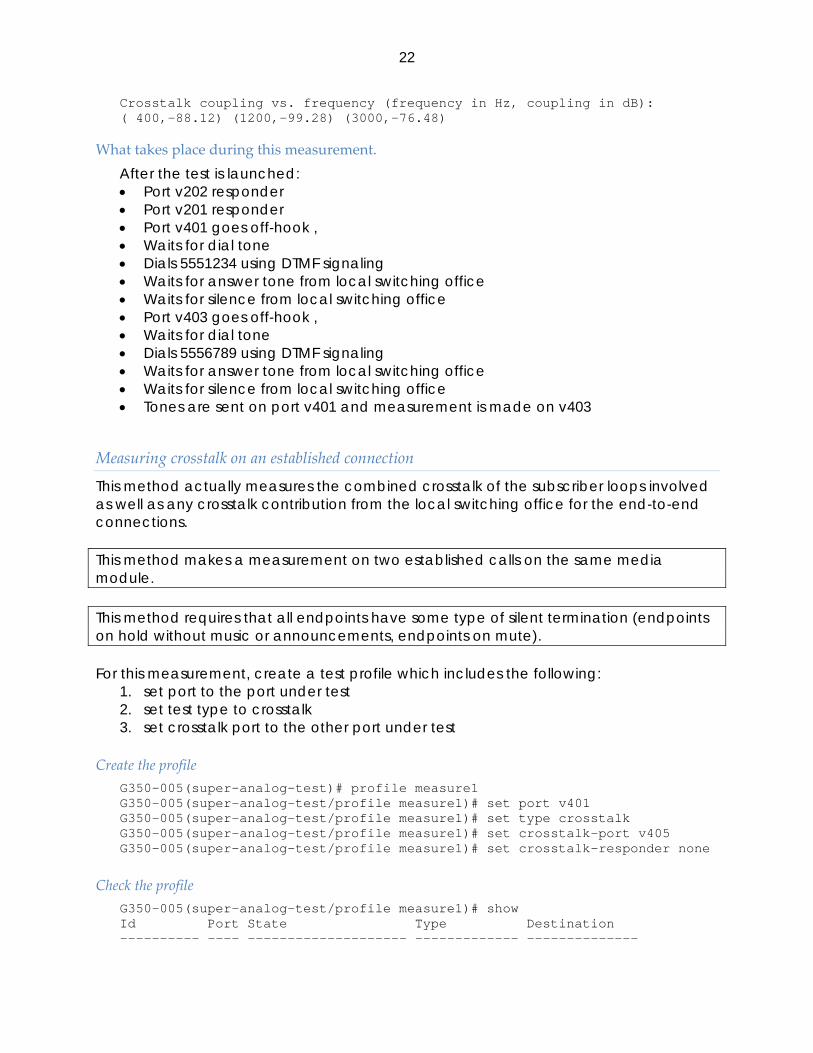
Crosstalk coupling vs. frequency (frequency in Hz, coupling in dB): ( 400,-88.12) (1200,-99.28) (3000,-76.48)
What takes place during this measurement. After the test is launched: • Port v202 responder • Port v201 responder • Port v401 goes off-hook , • Waits for dial tone • Dials 5551234 using DTMF signaling • Waits for answer tone from local switching office • Waits for silence from local switching office • Port v403 goes off-hook , • Waits for dial tone • Dials 5556789 using DTMF signaling • Waits for answer tone from local switching office • Waits for silence from local switching office • Tones are sent on port v401 and measurement is made on v403
Measuring crosstalk on an established connection
This method actually measures the combined crosstalk of the subscriber loops involved as well as any crosstalk contribution from the local switching office for the end-to-end connections. This method makes a measurement on two established calls on the same media module. This method requires that all endpoints have some type of silent termination (endpoints on hold without music or announcements, endpoints on mute).
For this measurement, create a test profile which includes the following:
1. set port to the port under test 2. set test type to crosstalk 3. set crosstalk port to the other port under test
Create the profile G350-005(super-analog-test)# profile measure1 G350-005(super-analog-test/profile measure1)# set port v401 G350-005(super-analog-test/profile measure1)# set type crosstalk G350-005(super-analog-test/profile measure1)# set crosstalk-port v405 G350-005(super-analog-test/profile measure1)# set crosstalk-responder none
Check the profile G350-005(super-analog-test/profile measure1)# show Id Port State Type Destination ---------- ---- -------------------- ------------- --------------

23
measure1 v401 idle crosstalk - Resp. Resp. type X. Port X. Destination X. Resp. X. Resp. type ----- ---------- ------- -------------- -------- ------------- - - v405 - - - Done! G350-005(super-analog-test/profile measure1)# exit
Run the profile G350-005(super-analog-test)# launch measure1
Get the results G350-005(super-analog-test)# profile measure1 G350-005(super-analog-test/profile measure1)# show result Crosstalk coupling vs. frequency (frequency in Hz, coupling in dB): ( 400,-88.12) (1200,-99.28) (3000,-76.48)
What takes place during this measurement. After the test is launched: • Tones are sent on port v401 and measurement is made on v405

24
Local Echo
Hybrid Balance
Examples
Measuring Hybrid Balance on the Subscriber loop
Far End is Local Switching Office
This method is the most accurate way for measuring subscriber loop hybrid balance. However it involves using the local switching office’s TEST100 test line. Measuring the subscriber loop when the far end is the local switching office can only be made on loop-start and ground start trunks since the measurement requires originating a call from the port under test.
For this measurement, create a test profile which includes the following:
1. set port to the port under test 2. set test type to balance 3. set destination to the number of the local switching office’s TEST100 responder
Create the profile G350-005(super-analog-test)# profile measure1 G350-005(super-analog-test/profile measure1)# set port v401 G350-005(super-analog-test/profile measure1)# set type balance G350-005(super-analog-test/profile measure1)# set destination 7771234
Check the profile G350-005(super-analog-test/profile measure1)# show Id Port State Type Destination ---------- ---- -------------------- ------------- -------------- measure1 v401 idle balance 7771234 Resp. Resp. type X. Port X. Destination X. Resp. X. Resp. type ----- ---------- ------- -------------- -------- ------------- - - - - - - Done! G350-005(super-analog-test/profile measure1)# exit
Run the profile G350-005(super-analog-test)# launch measure1

25
Get the results G350-005(super-analog-test)# profile measure1 G350-005(super-analog-test/profile measure1)# show result Trans-hybrid Loss vs. frequency (frequency in Hz, loss in dB): ( 200,+7.45) ( 300,+6.22) ( 400,+6.12) ( 500,+6.10) ( 600,+6.10) ( 700,+6.10) ( 800,+6.11) ( 900,+6.11) (1000,+6.10) (1100,+6.09) (1200,+6.06) (1300,+6.04) (1400,+6.01) (1500,+5.98) (1600,+5.96) (1700,+5.94) (1800,+5.92) (1900,+5.92) (2000,+5.92) (2100,+5.93) (2200,+5.95) (2300,+5.97) (2400,+5.99) (2500,+6.01) (2600,+6.02) (2700,+6.03) (2800,+6.04) (2900,+6.03) (3000,+6.02) (3100,+5.99) (3200,+5.95) (3300,+5.98) (3400,+6.34)
What takes place during this measurement. After the test is launched: • Port v401 goes off-hook , • Waits for dial tone • Dials 7771234 using DTMF signaling • Waits for answer tone from local switching office • Waits for silence from local switching office • Makes the measurement
Far end is another port in the gateway
The results of this measurement will include reflections from the far end termination.
When making this type of measurement, the responder can be any trunk type (loop-start, ground-start, DID). However the other port under test can only be a loop-start or ground start trunk since the measurement requires originating a call from this port.
For this measurement, create a test profile which includes the following:
1. set port to one of the ports under test 2. set responder port to the other port under test 3. set responder type to 100 4. set test type to balance 5. set destination to the responder port’s local switching office telephone number
Create the profile G350-005(super-analog-test)# profile measure1 G350-005(super-analog-test/profile measure1)# set port v401 G350-005(super-analog-test/profile measure1)# set responder v402 G350-005(super-analog-test/profile measure1)# set responder-type 100 G350-005(super-analog-test/profile measure1)# set type balance G350-005(super-analog-test/profile measure1)# set destination 5551234
Check the profile G350-005(super-analog-test/profile measure1)# show

26
Id Port State Type Destination ---------- ---- -------------------- ------------- -------------- measure1 v401 idle balance 5551234 Resp. Resp. type X. Port X. Destination X. Resp. X. Resp. type ----- ---------- ------- -------------- -------- ------------- v402 100 - - - - Done! G350-005(super-analog-test/profile measure1)# exit
Run the profile G350-005(super-analog-test)# launch measure1
Get the results G350-005(super-analog-test)# profile measure1 G350-005(super-analog-test/profile measure1)# show result Trans-hybrid Loss vs. frequency (frequency in Hz, loss in dB): ( 200,+7.45) ( 300,+6.22) ( 400,+6.12) ( 500,+6.10) ( 600,+6.10) ( 700,+6.10) ( 800,+6.11) ( 900,+6.11) (1000,+6.10) (1100,+6.09) (1200,+6.06) (1300,+6.04) (1400,+6.01) (1500,+5.98) (1600,+5.96) (1700,+5.94) (1800,+5.92) (1900,+5.92) (2000,+5.92) (2100,+5.93) (2200,+5.95) (2300,+5.97) (2400,+5.99) (2500,+6.01) (2600,+6.02) (2700,+6.03) (2800,+6.04) (2900,+6.03) (3000,+6.02) (3100,+5.99) (3200,+5.95) (3300,+5.98) (3400,+6.34)
What takes place during this measurement. After the test is launched: • Port v402 is configured as a TEST100 line • Port v401 goes off-hook • Port v401 waits for dial tone • Port v401 Dial 5551234 using DTMF signaling • Port v401 then waits answer tone from port v402 • Port v402 detects ringing and answers • Port V402 sends answer tone then silence • Port v401 waits for silence then makes the measurement
Measuring End to End hybrid balance
Making the measurement from the gateway
This method requires that test equipment be connected to the trunk at the far end and that the test equipment is set up to be a TEST 100 test line. The results of this measurement will include reflections from the far end termination. When making this type of measurement, the port under test can only be a loop-start or ground start trunk since the measurement requires originating a call from this port.

27
For this measurement, create a test profile which includes the following: 1. set port to the port under test 2. set test type to balance 3. set destination to the telephone number of the line connected to the test
equipment.
Create the profile G350-005(super-analog-test)# profile measure1 G350-005(super-analog-test/profile measure1)# set port v401 G350-005(super-analog-test/profile measure1)# set type balance G350-005(super-analog-test/profile measure1)# set destination 2015551234
Check the profile G350-005(super-analog-test/profile measure1)# show Id Port State Type Destination ---------- ---- -------------------- ------------- -------------- measure1 v401 idle balance 2015551234 Resp. Resp. type X. Port X. Destination X. Resp. X. Resp. type ----- ---------- ------- -------------- -------- ------------- - - - - - - Done! G350-005(super-analog-test/profile measure1)# exit
Run the profile G350-005(super-analog-test)# launch measure1
Get the results G350-005(super-analog-test)# profile measure1 G350-005(super-analog-test/profile measure1)# show result Trans-hybrid Loss vs. frequency (frequency in Hz, loss in dB): ( 200,+7.45) ( 300,+6.22) ( 400,+6.12) ( 500,+6.10) ( 600,+6.10) ( 700,+6.10) ( 800,+6.11) ( 900,+6.11) (1000,+6.10) (1100,+6.09) (1200,+6.06) (1300,+6.04) (1400,+6.01) (1500,+5.98) (1600,+5.96) (1700,+5.94) (1800,+5.92) (1900,+5.92) (2000,+5.92) (2100,+5.93) (2200,+5.95) (2300,+5.97) (2400,+5.99) (2500,+6.01) (2600,+6.02) (2700,+6.03) (2800,+6.04) (2900,+6.03) (3000,+6.02) (3100,+5.99) (3200,+5.95) (3300,+5.98) (3400,+6.34)
What takes place during this measurement. After the test is launched: • Port v401 goes off-hook , • Waits for dial tone • Dials 2015551234 using DTMF signaling • Waits for answer tone from far end • The test equipment goes off-hook and sends answer tone then silence • Port v401 detects answer tone, waits for silence then makes the measurement
28
Measuring hybrid balance on an established connection
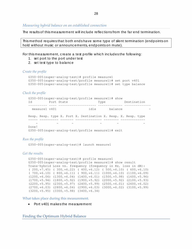
The results of this measurement will include reflections from the far end termination. This method requires that both ends have some type of silent termination (endpoints on hold without music or announcements, endpoints on mute).
For this measurement, create a test profile which includes the following:
1. set port to the port under test 2. set test type to balance
Create the profile G350-005(super-analog-test)# profile measure1 G350-005(super-analog-test/profile measure1)# set port v401 G350-005(super-analog-test/profile measure1)# set type balance
Check the profile G350-005(super-analog-test/profile measure1)# show Id Port State Type Destination ---------- ---- -------------------- ------------- -------------- measure1 v401 idle balance - Resp. Resp. type X. Port X. Destination X. Resp. X. Resp. type ----- ---------- ------- -------------- -------- ------------- - - - - - - Done! G350-005(super-analog-test/profile measure1)# exit
Run the profile G350-005(super-analog-test)# launch measure1
Get the results G350-005(super-analog-test)# profile measure1 G350-005(super-analog-test/profile measure1)# show result Trans-hybrid Loss vs. frequency (frequency in Hz, loss in dB): ( 200,+7.45) ( 300,+6.22) ( 400,+6.12) ( 500,+6.10) ( 600,+6.10) ( 700,+6.10) ( 800,+6.11) ( 900,+6.11) (1000,+6.10) (1100,+6.09) (1200,+6.06) (1300,+6.04) (1400,+6.01) (1500,+5.98) (1600,+5.96) (1700,+5.94) (1800,+5.92) (1900,+5.92) (2000,+5.92) (2100,+5.93) (2200,+5.95) (2300,+5.97) (2400,+5.99) (2500,+6.01) (2600,+6.02) (2700,+6.03) (2800,+6.04) (2900,+6.03) (3000,+6.02) (3100,+5.99) (3200,+5.95) (3300,+5.98) (3400,+6.34)
What takes place during this measurement. • Port v401 makes the measurement
Finding the Optimum Hybrid Balance

29
Measures THL for all balance settings, ranks the results in order of best match first.
Match on Subscriber loop
Far End is Local Switching Office
This method is the most accurate way for measuring subscriber loop hybrid balance and obtaining the best match. However it involves using the local switching office’s TEST100 test line. Measuring the subscriber loop when the far end is the local switching office can only be made on loop-start and ground start trunks since the measurement requires originating a call from the port under test.
For this measurement, create a test profile which includes the following:
1. set port to the port under test 2. set test type to match 3. set destination to the number of the local switching office’s TEST100 responder
Create the profile G350-005(super-analog-test)# profile measure1 G350-005(super-analog-test/profile measure1)# set port v401 G350-005(super-analog-test/profile measure1)# set type match G350-005(super-analog-test/profile measure1)# set destination 7771234
Check the profile G350-005(super-analog-test/profile measure1)# show Id Port State Type Destination ---------- ---- -------------------- ------------- -------------- measure1 v401 idle match 7771234 Resp. Resp. type X. Port X. Destination X. Resp. X. Resp. type ----- ---------- ------- -------------- -------- ------------- - - - - - - Done! G350-005(super-analog-test/profile measure1)# exit
Run the profile G350-005(super-analog-test)# launch measure1
Get the results G350-005(super-analog-test)# profile measure1 G350-005(super-analog-test/profile measure1)# show result Coefficient match, (coefficient table, ERL in dB): ( 7, +6.49) ( 4, +4.19) ( 2, +3.88) ( 1, +3.46) ( 6, +3.44) ( 8, +3.41) ( 0, +3.33) ( 3, +3.03) ( 5, +2.63) Measurements are shown in the order of best match first. Coefficient table 7 is the best match.

30
What takes place during this measurement. After the test is launched: • Port v401 goes off-hook , • Waits for dial tone • Dials 7771234 using DTMF signaling • Waits for answer tone from local switching office • Waits for silence from local switching office • Makes the measurement
Far end is another port in the gateway
The results of this measurement will include reflections from the far end termination. When making this type of measurement, the responder can be any trunk type (loop-start, ground-start, DID). However the other port under test can only be a loop-start or ground start trunk since the measurement requires originating a call from this port.
For this measurement, create a test profile which includes the following:
1. set port to one of the ports under test 2. set responder port to the other port under test 3. set responder type to 100 4. set test type to match 5. set destination to the responder port’s local switching office telephone number
Create the profile G350-005(super-analog-test)# profile measure1 G350-005(super-analog-test/profile measure1)# set port v401 G350-005(super-analog-test/profile measure1)# set responder v402 G350-005(super-analog-test/profile measure1)# set responder-type 100 G350-005(super-analog-test/profile measure1)# set type match G350-005(super-analog-test/profile measure1)# set destination 5551234
Check the profile G350-005(super-analog-test/profile measure1)# show Id Port State Type Destination ---------- ---- -------------------- ------------- -------------- measure1 v401 idle match 5551234 Resp. Resp. type X. Port X. Destination X. Resp. X. Resp. type ----- ---------- ------- -------------- -------- ------------- v402 100 - - - - Done! G350-005(super-analog-test/profile measure1)# exit
Run the profile G350-005(super-analog-test)# launch measure1
Get the results

31
G350-005(super-analog-test)# profile measure1 G350-005(super-analog-test/profile measure1)# show result Coefficient match, (coefficient table, ERL in dB): ( 7, +6.49) ( 4, +4.19) ( 2, +3.88) ( 1, +3.46) ( 6, +3.44) ( 8, +3.41) ( 0, +3.33) ( 3, +3.03) ( 5, +2.63) Measurements are shown in the order of best match first. Coefficient table 7 is the best match.
What takes place during this measurement. After the test is launched: • Port v402 is configured as a TEST100 line • Port v401 goes off-hook • Port v401 waits for dial tone • Port v401 Dial 5551234 using DTMF signaling • Port v401 then waits answer tone from port v402 • Port v402 detects ringing and answers • Port V402 sends answer tone then silence • Port v401 waits for silence then makes the measurement
Match on an end to end connection
Making the measurement from the gateway
The results of this measurement will include reflections from the far end termination. When making this type of measurement, the port under test can only be a loop-start or ground start trunk since the measurement requires originating a call from this port. This method requires that test equipment be connected to the trunk at the far end and that the test equipment is set up to be a TEST 100 responder.
For this measurement, create a test profile which includes the following:
1. set port to the port under test 2. set test type to balance 3. set destination to the telephone number of the line connected to the test
equipment.
Create the profile G350-005(super-analog-test)# profile measure1 G350-005(super-analog-test/profile measure1)# set port v401 G350-005(super-analog-test/profile measure1)# set type match G350-005(super-analog-test/profile measure1)# set destination 2015551234
Check the profile G350-005(super-analog-test/profile measure1)# show Id Port State Type Destination ---------- ---- -------------------- ------------- -------------- measure1 v401 idle match 2015551234
32
Resp. Resp. type X. Port X. Destination X. Resp. X. Resp. type ----- ---------- ------- -------------- -------- ------------- - - - - - - Done! G350-005(super-analog-test/profile measure1)# exit
Run the profile G350-005(super-analog-test)# launch measure1
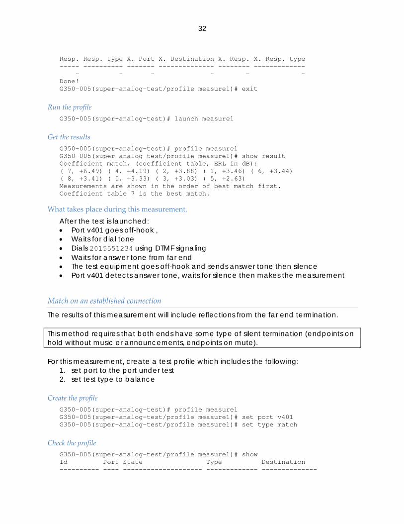
Get the results G350-005(super-analog-test)# profile measure1 G350-005(super-analog-test/profile measure1)# show result Coefficient match, (coefficient table, ERL in dB): ( 7, +6.49) ( 4, +4.19) ( 2, +3.88) ( 1, +3.46) ( 6, +3.44) ( 8, +3.41) ( 0, +3.33) ( 3, +3.03) ( 5, +2.63) Measurements are shown in the order of best match first. Coefficient table 7 is the best match.
What takes place during this measurement. After the test is launched: • Port v401 goes off-hook , • Waits for dial tone • Dials 2015551234 using DTMF signaling • Waits for answer tone from far end • The test equipment goes off-hook and sends answer tone then silence • Port v401 detects answer tone, waits for silence then makes the measurement
Match on an established connection
The results of this measurement will include reflections from the far end termination. This method requires that both ends have some type of silent termination (endpoints on hold without music or announcements, endpoints on mute).
For this measurement, create a test profile which includes the following:
1. set port to the port under test 2. set test type to balance
Create the profile G350-005(super-analog-test)# profile measure1 G350-005(super-analog-test/profile measure1)# set port v401 G350-005(super-analog-test/profile measure1)# set type match
Check the profile G350-005(super-analog-test/profile measure1)# show Id Port State Type Destination ---------- ---- -------------------- ------------- --------------

33
measure1 v401 idle match - Resp. Resp. type X. Port X. Destination X. Resp. X. Resp. type ----- ---------- ------- -------------- -------- ------------- - - - - - - Done! G350-005(super-analog-test/profile measure1)# exit
Run the profile G350-005(super-analog-test)# launch measure1
Get the results G350-005(super-analog-test)# profile measure1 G350-005(super-analog-test/profile measure1)# show result Coefficient match, (coefficient table, ERL in dB): ( 7, +6.49) ( 4, +4.19) ( 2, +3.88) ( 1, +3.46) ( 6, +3.44) ( 8, +3.41) ( 0, +3.33) ( 3, +3.03) ( 5, +2.63) Measurements are shown in the order of best match first. Coefficient table 7 is the best match.
What takes place during this measurement. • Port v401 makes the measurement
Using the Optimum Hybrid Balance
To change the hybrid balance coefficients table to one that is a better match for the particular port:
G350-31(analog-test)# set balance v401 4

34
CLI reference
Errors
condition Corresponding
profile stateMedia module went out of service during the test failed-interrupted General measurement failure Failed Hardware does not support this particular test failed-hardware Abort, port busy failed-port-busy Abort, CM seized the port aborted-port-seized Incorrect port type failed-port-type Incorrect port state failed-port-state No dialtone failed-dialtone No answer failed-answer Far end disconnected the call Failed-farend No test tone failed-no-test-tone Tone detected where there should be silence failed-heard-tone Measurement error failed-measurement Crosstalk port, no dialtone failed-x-dialtone Crosstalk port, no answer failed-x-answer Crosstalk port, far end disconnected failed-x-farend Crosstalk port, sync error failed-x-sync Crosstalk responder port, far end disconnected failed-x-resp-farend Crosstalk responder port, sync error failed-x-resp-sync
Recommended