Vapor and Combined Power Vapor and Combined Power CyclesCycles
Chapter 10Chapter 10
Introduction to Power and Introduction to Power and Refrigeration CyclesRefrigeration Cycles
Two important areas of application for Two important areas of application for thermodynamics are Power Generation and thermodynamics are Power Generation and Refrigeration.Refrigeration.Both power generation and refrigeration are Both power generation and refrigeration are usually accomplished by a system that usually accomplished by a system that operates on a thermodynamics cycle.operates on a thermodynamics cycle.Thermodynamics cycles can be divided into Thermodynamics cycles can be divided into two generation categories:two generation categories:
Power CyclesPower CyclesRefrigeration Cycles Refrigeration Cycles
Introduction to Power and Introduction to Power and Refrigeration CyclesRefrigeration Cycles
The devices or systems used to produce a The devices or systems used to produce a net power outputnet power output are often called are often called enginesengines and the thermodynamics cycles they operate and the thermodynamics cycles they operate on are called on are called power cyclepower cycle..
The devices or systems use to produce The devices or systems use to produce refrigerationrefrigeration are called are called refrigeratorsrefrigerators , , air air conditionersconditioners or or heat pumpsheat pumps and the cycles and the cycles they operates on are called they operates on are called refrigeration refrigeration cycles.cycles.
The Carnot Vapor CycleThe Carnot Vapor Cycle
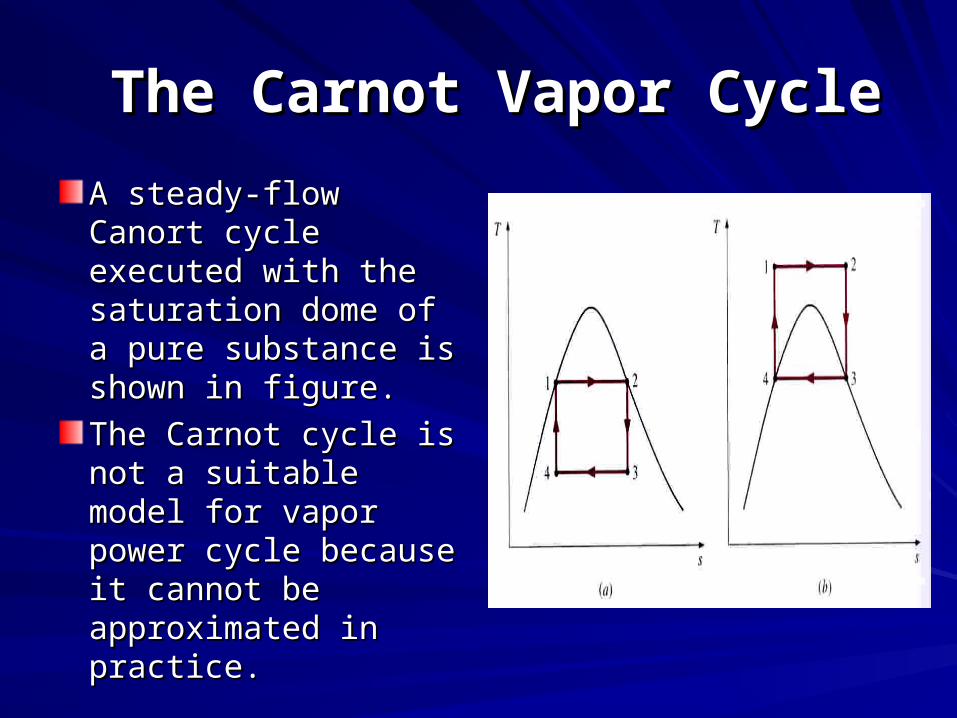
A steady-flow Canort A steady-flow Canort cycle executed with cycle executed with the saturation dome the saturation dome of a pure substance is of a pure substance is shown in figure.shown in figure.
The Carnot cycle is The Carnot cycle is not a suitable model not a suitable model for vapor power cycle for vapor power cycle because it cannot be because it cannot be approximated in approximated in practice. practice.
Rankine CycleRankine CycleThe impracticalities associated with Carnot cycle The impracticalities associated with Carnot cycle can be eliminated by:can be eliminated by:
1.1. superheating the steam in the boiler.superheating the steam in the boiler.
2.2. condensing it completely in the condenser.condensing it completely in the condenser.
Such cycle is called the Rankine cycle, Such cycle is called the Rankine cycle, which is which is the ideal cycle for vapor power plantsthe ideal cycle for vapor power plants. .
The ideal Rankine cycle dose not involve any The ideal Rankine cycle dose not involve any internal irreversibilities internal irreversibilities
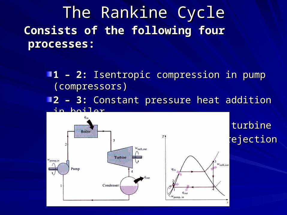
The Rankine CycleThe Rankine Cycle Consists of the following four processes:Consists of the following four processes:
1 – 2:1 – 2: Isentropic compression in pump (compressors) Isentropic compression in pump (compressors)
2 – 3:2 – 3: Constant pressure heat addition in boiler Constant pressure heat addition in boiler
3 – 4: 3 – 4: Isentropic expansion in turbineIsentropic expansion in turbine
4 – 1: 4 – 1: Constant pressure heat rejection in a condenserConstant pressure heat rejection in a condenser
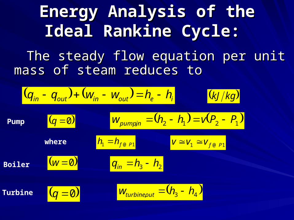
Energy Analysis of the Ideal Energy Analysis of the Ideal Rankine Cycle:Rankine Cycle:
The steady flow equation per unit mass of The steady flow equation per unit mass of steam reduces to steam reduces to
ieoutinoutin hhwwqq kgkJ
Pump 1212, PPvhhw inpump
Boiler 0w
0q
where 1@1 Pfhh 1@1 Pfvvv
23 hhqin
Turbine 43, hhw outturbine 0q
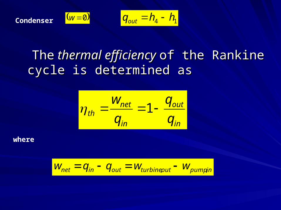
TheThe thermal efficiency thermal efficiency of the Rankine cycle of the Rankine cycle is determined asis determined as
Condenser
where
0w 14 hhqout
in
out
in
netth q
q
q
w 1
inpumpoutturbineoutinnet wwqqw ,,
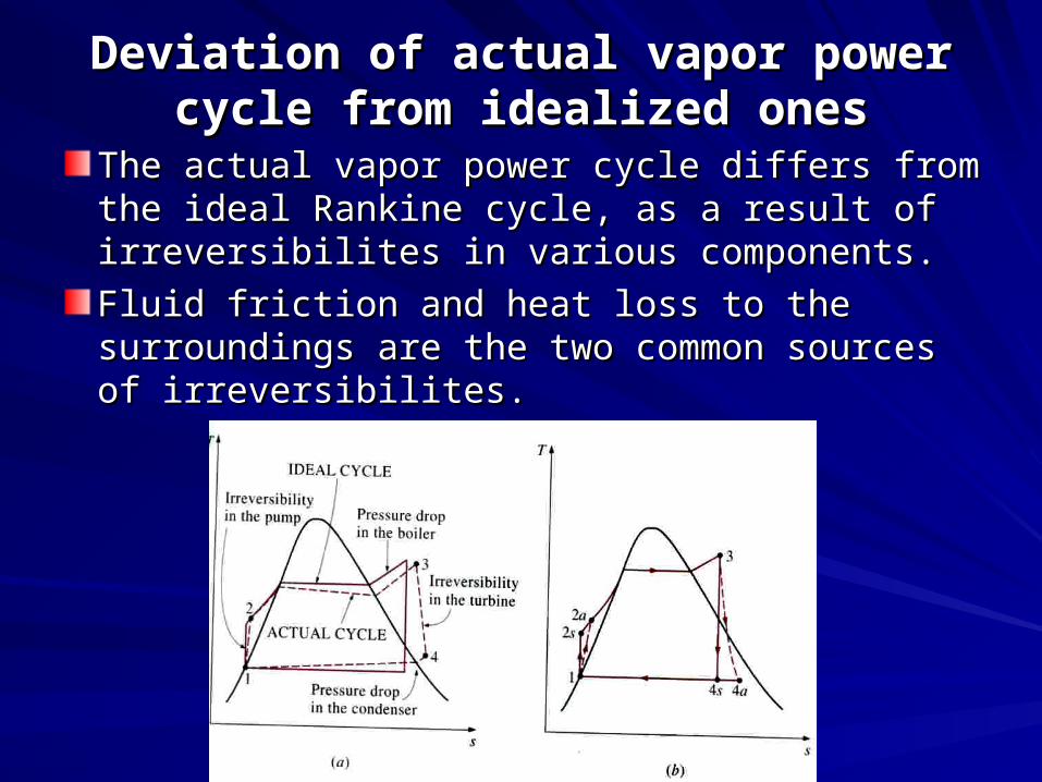
Deviation of actual vapor power cycle Deviation of actual vapor power cycle from idealized onesfrom idealized ones
The actual vapor power cycle differs from the The actual vapor power cycle differs from the ideal Rankine cycle, as a result of irreversibilites ideal Rankine cycle, as a result of irreversibilites in various components.in various components.
Fluid friction and heat loss to the surroundings Fluid friction and heat loss to the surroundings are the two common sources of irreversibilites.are the two common sources of irreversibilites.
Fluid friction causes pressure drop in the Fluid friction causes pressure drop in the boiler, the condenser and the piping boiler, the condenser and the piping between various components. between various components.
Also the pressure at the turbine inlet is Also the pressure at the turbine inlet is somewhat lower than that at the boiler exit somewhat lower than that at the boiler exit due to the pressure drop in the connecting due to the pressure drop in the connecting pipes.pipes.
To compensate for these pressure drops, To compensate for these pressure drops, the water must be pumped to a sufficiently the water must be pumped to a sufficiently higher pressure than the ideal cycle. This higher pressure than the ideal cycle. This requires a requires a large pump and larger work large pump and larger work input to the pumpinput to the pump..
The other major source of irreversibility is The other major source of irreversibility is the heat loss from the steam to the the heat loss from the steam to the surrounding as the steam flows through surrounding as the steam flows through various components.various components.
Particular important are the irreversibilites Particular important are the irreversibilites occurring within the pump and the turbine.occurring within the pump and the turbine.
A pump require a greater work input, and A pump require a greater work input, and a turbine produces a smaller work output a turbine produces a smaller work output as a result of irreversibilties.as a result of irreversibilties.
Under the ideal condition the flow through Under the ideal condition the flow through these devices is isentropic.these devices is isentropic.
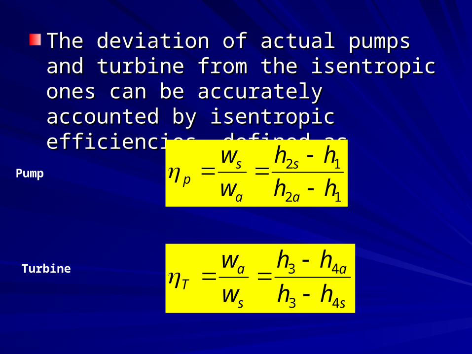
The deviation of actual pumps and turbine The deviation of actual pumps and turbine from the isentropic ones can be accurately from the isentropic ones can be accurately accounted by isentropic efficiencies, accounted by isentropic efficiencies, defined as defined as
12
12
hh
hh
w
w
a
s
a
sp
Pump
Turbine
s
a
s
aT hh
hh
w
w
43
43
Increasing the efficiency of Increasing the efficiency of the Rankine cycle?the Rankine cycle?
Three ways:Three ways:
1.1. Lowering the condenser pressure (Lowers TLowering the condenser pressure (Lowers T low, low,
avav).).
2.2. Superheating the steam to high temperatures Superheating the steam to high temperatures (Increases T(Increases Thigh, avhigh, av).).
3.3. Increasing the boiler pressure (Increases TIncreasing the boiler pressure (Increases Thigh, avhigh, av))
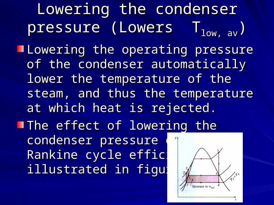
Lowering the condenser pressure Lowering the condenser pressure (Lowers T(Lowers Tlow, avlow, av))
Lowering the operating pressure of the Lowering the operating pressure of the condenser automatically lower the condenser automatically lower the temperature of the steam, and thus the temperature of the steam, and thus the temperature at which heat is rejected.temperature at which heat is rejected.
The effect of lowering the condenser The effect of lowering the condenser pressure on the Rankine cycle efficiency is pressure on the Rankine cycle efficiency is illustrated in figure illustrated in figure
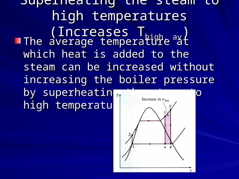
Superheating the steam to high Superheating the steam to high temperatures (Increases Ttemperatures (Increases Thigh, avhigh, av))The average temperature at which heat is The average temperature at which heat is added to the steam can be increased added to the steam can be increased without increasing the boiler pressure by without increasing the boiler pressure by superheating the steam to high superheating the steam to high temperatures. temperatures.
Superheating the steam to high Superheating the steam to high temperatures (Increases Ttemperatures (Increases Thigh, avhigh, av))
Superheating the steam to higher Superheating the steam to higher temperatures has very desirable effect: It temperatures has very desirable effect: It decreases the moisture content of the decreases the moisture content of the steam at the turbine exit as can be seen in steam at the turbine exit as can be seen in T-T-ss diagram. diagram.
The temperature to which steam can be The temperature to which steam can be superheated is limited by metallurgical superheated is limited by metallurgical consideration. consideration.
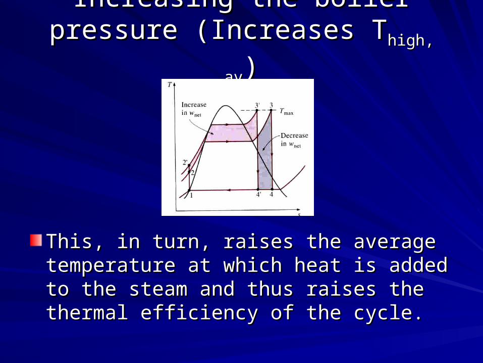
Increasing the boiler pressure Increasing the boiler pressure (Increases T(Increases Thigh, avhigh, av))
The average temperature during the heat The average temperature during the heat addition process is to increase the addition process is to increase the operating pressure of the boiler, which operating pressure of the boiler, which automatically raises the temperature at automatically raises the temperature at which boiling take place. which boiling take place.
This, in turn, raises the average This, in turn, raises the average temperature at which heat is added to the temperature at which heat is added to the steam and thus raises the thermal steam and thus raises the thermal efficiency of the cycle.efficiency of the cycle.
Increasing the boiler pressure Increasing the boiler pressure (Increases T(Increases Thigh, avhigh, av))
This, in turn, raises the average This, in turn, raises the average temperature at which heat is added to the temperature at which heat is added to the steam and thus raises the thermal steam and thus raises the thermal efficiency of the cycle.efficiency of the cycle.
The Ideal Reheat Rankine CycleThe Ideal Reheat Rankine Cycle
The efficiency of the Rankine cycle can The efficiency of the Rankine cycle can increase by expanding the steam in the increase by expanding the steam in the turbine in two stages, and turbine in two stages, and reheatreheat it in it in between.between.
In other words, modify the simple ideal In other words, modify the simple ideal Rankine cycle with reheat process.Rankine cycle with reheat process.
Reheating is a practical solution to the Reheating is a practical solution to the excessive moisture problem in turbines, excessive moisture problem in turbines, and it is commonly used in modern steam and it is commonly used in modern steam power plants. power plants.
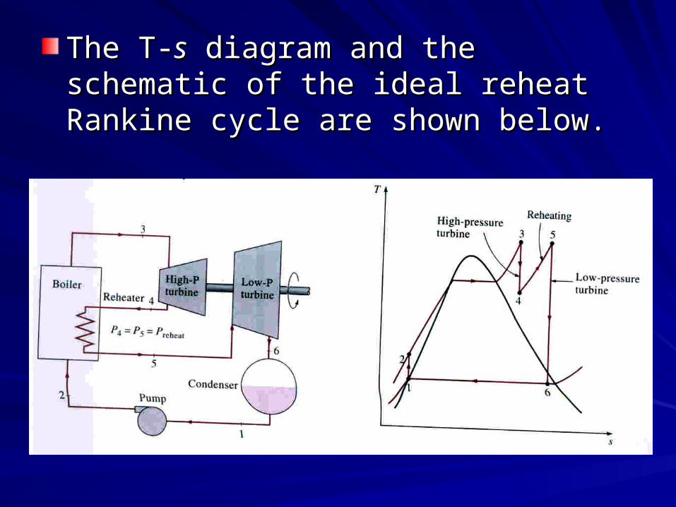
The T-The T-ss diagram and the schematic of the diagram and the schematic of the ideal reheat Rankine cycle are shown ideal reheat Rankine cycle are shown below. below.
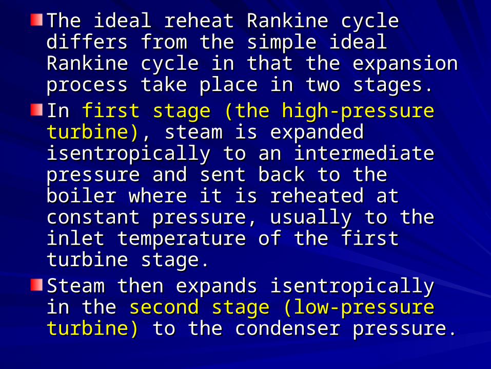
The ideal reheat Rankine cycle differs The ideal reheat Rankine cycle differs from the simple ideal Rankine cycle in that from the simple ideal Rankine cycle in that the expansion process take place in two the expansion process take place in two stages. stages. In In first stage (the high-pressure turbine)first stage (the high-pressure turbine), , steam is expanded isentropically to an steam is expanded isentropically to an intermediate pressure and sent back to the intermediate pressure and sent back to the boiler where it is reheated at constant boiler where it is reheated at constant pressure, usually to the inlet temperature pressure, usually to the inlet temperature of the first turbine stage. of the first turbine stage. Steam then expands isentropically in the Steam then expands isentropically in the second stage (low-pressure turbine)second stage (low-pressure turbine) to the to the condenser pressure. condenser pressure.
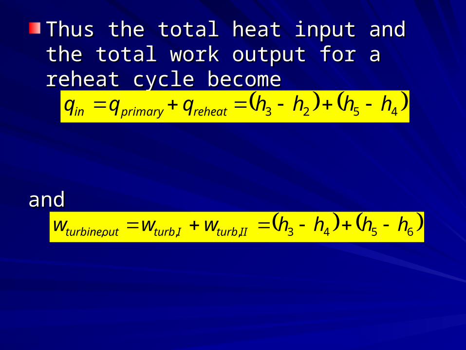
Thus the total heat input and the total work Thus the total heat input and the total work output for a reheat cycle becomeoutput for a reheat cycle become
andand
4523 hhhhqqq reheatprimaryin
6543,,, hhhhwww IIturbIturboutturbine

The Ideal Regenerative Rankine The Ideal Regenerative Rankine CycleCycle
The T-s diagram for the Rankine cycle The T-s diagram for the Rankine cycle shows that heat transferred to the working shows that heat transferred to the working fluid during process 2-2’ at a relatively low fluid during process 2-2’ at a relatively low temperature. temperature.
This lowers the average heat-addition This lowers the average heat-addition temperature and thus the cycle efficiency.temperature and thus the cycle efficiency.
Another way of increasing the thermal Another way of increasing the thermal efficiency of the Rankine cycle is by efficiency of the Rankine cycle is by regenerationregeneration. During a regeneration . During a regeneration process, liquid water (feedwater) leaves process, liquid water (feedwater) leaves the pump is heated by steam bled off the the pump is heated by steam bled off the turbine at some intermediate pressure in turbine at some intermediate pressure in devices called feedwater heaters.devices called feedwater heaters.
There are two type of feedwater HeatersThere are two type of feedwater HeatersOpen Feedwater HeaterOpen Feedwater Heater
Closed Feedwater Heater Closed Feedwater Heater
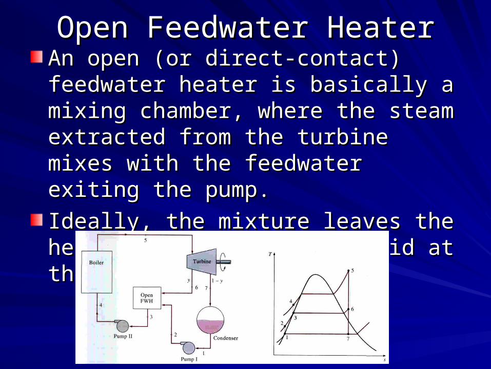
Open Feedwater HeaterOpen Feedwater HeaterAn open (or direct-contact) feedwater An open (or direct-contact) feedwater heater is basically a mixing chamber, heater is basically a mixing chamber, where the steam extracted from the where the steam extracted from the turbine mixes with the feedwater exiting turbine mixes with the feedwater exiting the pump. the pump.
Ideally, the mixture leaves the heater as a Ideally, the mixture leaves the heater as a saturated liquid at the heater pressure. saturated liquid at the heater pressure.
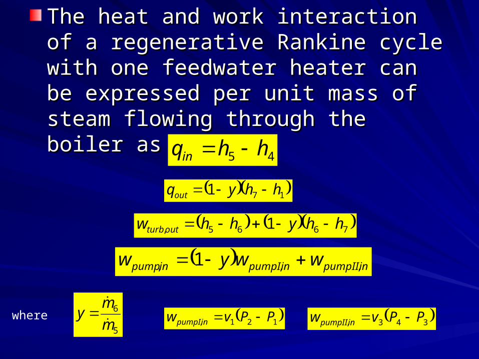
The heat and work interaction of a The heat and work interaction of a regenerative Rankine cycle with one regenerative Rankine cycle with one feedwater heater can be expressed per feedwater heater can be expressed per unit mass of steam flowing through the unit mass of steam flowing through the boiler as follows: boiler as follows:
45 hhqin
171 hhyqout
7665, 1 hhyhhw outturb
inpumpIIinpumpIinpump wwyw ,,, 1
5
6
m
my
121, PPvw inpumpI 343, PPvw inpumpII where
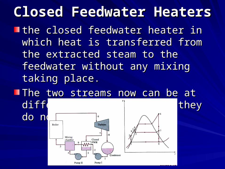
Closed Feedwater HeatersClosed Feedwater Heaters the closed feedwater heater in which heat the closed feedwater heater in which heat is transferred from the extracted steam to is transferred from the extracted steam to the feedwater without any mixing taking the feedwater without any mixing taking place. place.
The two streams now can be at different The two streams now can be at different pressure, since they do not mix. pressure, since they do not mix.
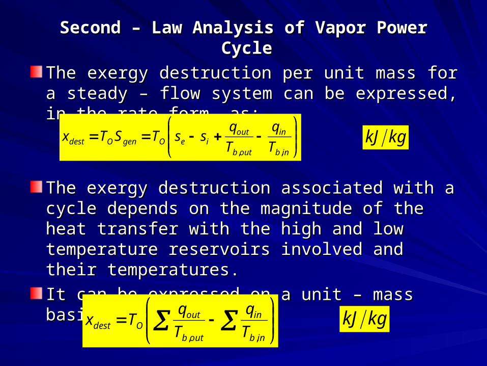
Second – Law Analysis of Vapor Power CycleSecond – Law Analysis of Vapor Power Cycle
The exergy destruction per unit mass for a The exergy destruction per unit mass for a steady – flow system can be expressed, in the steady – flow system can be expressed, in the rate form, as:rate form, as:
The exergy destruction associated with a cycle The exergy destruction associated with a cycle depends on the magnitude of the heat transfer depends on the magnitude of the heat transfer with the high and low temperature reservoirs with the high and low temperature reservoirs involved and their temperatures.involved and their temperatures.
It can be expressed on a unit – mass basis as It can be expressed on a unit – mass basis as
inb
in
outb
outieOgenOdest T
q
T
qssTSTx
,,
kgkJ
inb
in
outb
outOdest T
q
T
qTx
,,
kgkJ
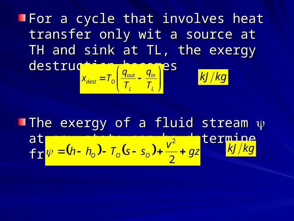
For a cycle that involves heat transfer only For a cycle that involves heat transfer only wit a source at TH and sink at TL, the wit a source at TH and sink at TL, the exergy destruction becomesexergy destruction becomes
The exergy of a fluid stream The exergy of a fluid stream at any state at any state can be determine from can be determine from
L
in
L
outOdest T
q
T
qTx
gzv
ssThh OOO 2
2
kgkJ
kgkJ
CogenerationCogeneration
The production of more than one useful The production of more than one useful form of energy (such as process heat and form of energy (such as process heat and electric power) from the same energy electric power) from the same energy source is called cogeneration. source is called cogeneration.
Cogeneration plants produce electric Cogeneration plants produce electric power while meeting the process heat power while meeting the process heat requirements of certain industrial requirements of certain industrial processes. processes.
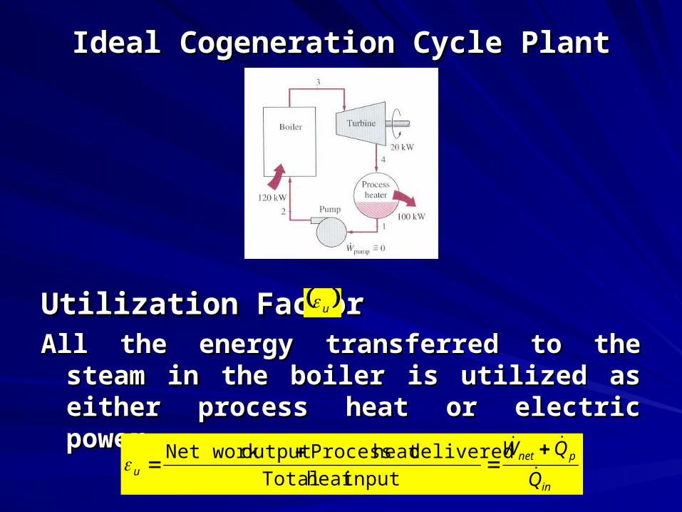
Ideal Cogeneration Cycle PlantIdeal Cogeneration Cycle Plant
Utilization Factor Utilization Factor All the energy transferred to the steam in the All the energy transferred to the steam in the
boiler is utilized as either process heat or boiler is utilized as either process heat or electric power.electric power.
u
in
pnetu Q
QW
inputheat Total
deliveredheat Process output Net work
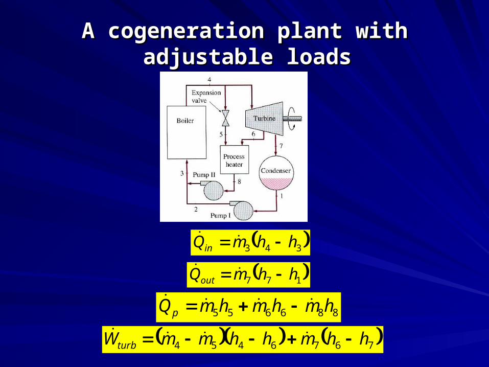
A cogeneration plant with adjustable A cogeneration plant with adjustable loadsloads
343 hhmQin
177 hhmQout
886655 hmhmhmQp
7676454 hhmhhmmWturb
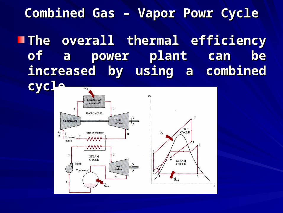
Combined Gas – Vapor Powr CycleCombined Gas – Vapor Powr Cycle
The overall thermal efficiency of a The overall thermal efficiency of a power plant can be increased by using power plant can be increased by using a combined cycle.a combined cycle.
Recommended