Technical GuideTechnical GuideTechnical GuideTechnical GuideTechnical Guide
Feature Overview and Configuration Guide
Virtual LANs (VLANs)
VLAN IntroductionThis guide describes Virtual LANs (VLANs), VLAN features and configuration on the
switch.
It begins with a description of what a VLAN is, its evolution and purpose, and also
provides the meaning of some common VLAN terminology.
This is followed with a detailed look at VLAN implementation. Port-based VLAN
membership is the most common way to split a network into sets of virtual LANs. We look
at how this is achieved using the VLAN tagging.
The use of double-tagging (or VLAN stacking) to tunnel VLANs across Layer 2 networks is
described, and an example is provided for the configuration of VLAN stacking.
Next we discuss private VLANs and the communication rules that limit what is possible
between devices operating within the VLAN. AlliedWare Plus™ has two private VLAN
solutions:
private VLANs for ports in Access Mode
private VLANs for ports in Trunked Mode
Configuration examples are provided for both of these solutions.
Then, we look at combining private VLANs with other features, such as: EPSR, ARP, LLDP,
GVRP, Link aggregation, and management servers. The guide ends with a section on
configuring protocol based VLANs and then describes how data counters are used to
count both the number of received frames or the number of received bytes (octets)
belonging to a particular VLAN.
x alliedtelesis.comC613-22001-00 REV C
Products and software version that apply to this guide
This guide applies to all AlliedWare Plus™ products, running version 5.4.4 or later.
However, not all features in this guide are supported on all products. To see whether a
product supports a particular feature or command, see the following documents:
The AlliedWare Plus Datasheet
The product’s Datasheet
The product’s Command Reference
These documents are available from the above links on our website at alliedtelesis.com.
Feature support may change in later versions. For the latest information, see the above
documents.
ContentsVLAN Introduction .............................................................................................................. 1
Products and software version that apply to this guide .............................................. 2
Virtual LANs........................................................................................................................ 4
What is a VLAN?.......................................................................................................... 4
The purpose of VLANs................................................................................................. 4
Using routers to segment LANs................................................................................... 5
Using switches to segment LANs................................................................................ 5
Domain terminology..................................................................................................... 6
Using VLANs to segment LANs................................................................................... 6
Implementing VLANs.......................................................................................................... 8
Port-based VLANs....................................................................................................... 8
Distributing a single VLAN across multiple switches................................................... 8
How does tagging work?............................................................................................. 9
Mixing tagged and untagged packets on the same port........................................... 10
Only accepting packets that match the port’s VLAN configuration (ingress filtering) 11
Configuring VLANs .................................................................................................... 12
VLAN Double Tagging (VLAN Stacking) ........................................................................... 14
How double-tagged VLANs work .............................................................................. 14
VLAN rules for double tagging................................................................................... 16
Configuring double-tagged VLANs............................................................................ 16
Private VLANs .................................................................................................................. 19
AlliedWare Plus private VLAN solutions .................................................................... 20
Private VLANs for Ports in Access Mode......................................................................... 20
Page 2 | Products and software version that apply to this guide
Membership rules for private VLANs in access mode ...............................................21
Promiscuous ports .....................................................................................................21
Host ports...................................................................................................................22
Private VLAN operation with ports in access mode...................................................23
Access mode private VLAN configuration examples .................................................25
Private VLANs for trunked ports.................................................................................27
Trunked port private VLAN configuration example.....................................................29
Mixed tagged and untagged private VLANs example................................................32
Combining Private VLANs with Other Features - Limitations ...........................................33
Using private VLANs with EPSR.................................................................................33
Using private VLANs with ARP...................................................................................33
Using private VLANs with LLDP .................................................................................34
Using private VLANs with GVRP ................................................................................34
Using private VLANs with link aggregation ................................................................34
Using private VLANs with management utility servers...............................................34
Protocol-Based VLANS.....................................................................................................35
Protocol based VLAN configuration example ............................................................36
VLAN Statistics .................................................................................................................38
Counter operation.......................................................................................................39
Products and software version that apply to this guide | Page 3
Virtual LANsA VLAN is a logical, software-defined subnetwork. It allows similar devices on the network
to be grouped together into one broadcast domain, irrespective of their physical position
in the network. Multiple VLANs can be used to group workstations, servers, and other
network equipment connected to the switch, according to similar data and security
requirements.
What is a VLAN?
In simple terms, a VLAN is a set of workstations within a LAN that can communicate with
each other as though they were on a single, isolated LAN. What does it mean to say that
they “communicate with each other as though they were on a single, isolated LAN”?
Among other things, it means that:
broadcast packets sent by one of the workstations will reach all the others in the VLAN.
broadcasts sent by one of the workstations in the VLAN will not reach any workstations
that are not in the VLAN.
broadcasts sent by workstations that are not in the VLAN will never reach workstations
that are in the VLAN.
the workstations can all communicate with each other without needing to go through
a gateway. For example, IP connections would be established by ARPing for the
destination.
IP and sending packets directly to the destination workstation—there would be no
need to send packets to the IP gateway to be forwarded on.
the workstations can communicate with each other using non-routable protocols.
The purpose of VLANs
The basic reason for splitting a network into VLANs is to reduce congestion on a large
LAN. To understand this problem, we need to look briefly at how LANs have developed
over the years. Initially LANs were very flat—all the workstations were connected to a
single piece of coaxial cable, or to sets of chained hubs. In a flat LAN, every packet that
any device puts onto the wire gets sent to every other device on the LAN.
As the number of workstations on the typical LAN grew, they started to become
hopelessly congested; there were just too many collisions, because most of the time
when a workstation tried to send a packet, it would find that the wire was already
occupied by a packet sent by some other device.
Page 4 | What is a VLAN?
This next section describes the three solutions for this congestion that were developed:
Using routers to segment LANs on page 5
Using switches to segment LANs on page 5
Using VLANs to segment LANs on page 6
Using routers to segment LANs
The early solution to this problem was to segment the network using routers. This would
split the network into a number of smaller LANs. There would be less workstations on
each LAN, and so less congestion.
Of course, routable data being sent between LANs would have to be routed, so the layer 3
addresses would have to be organized so that each LAN had an identifiable set of
addresses that could be routed to—such as an IP subnet or an AppleTalk zone. Non-
routable protocols would have to be bridged, which is not quite so congestion-reducing,
because bridges forward all broadcasts. But, at least for unicast packets, a bridge only
forwards packets if it knows that the destination address is not in the originating LAN.
Using switches to segment LANs
As switches became more available, there was a move from chained hubs to a set of hubs
connected to a switch. A switch only sends traffic to a given port if the traffic has to go to
that port. So switches have the effect of reducing congestion at workstations, by stopping
the workstations from seeing all the traffic from the other ports of the switch.
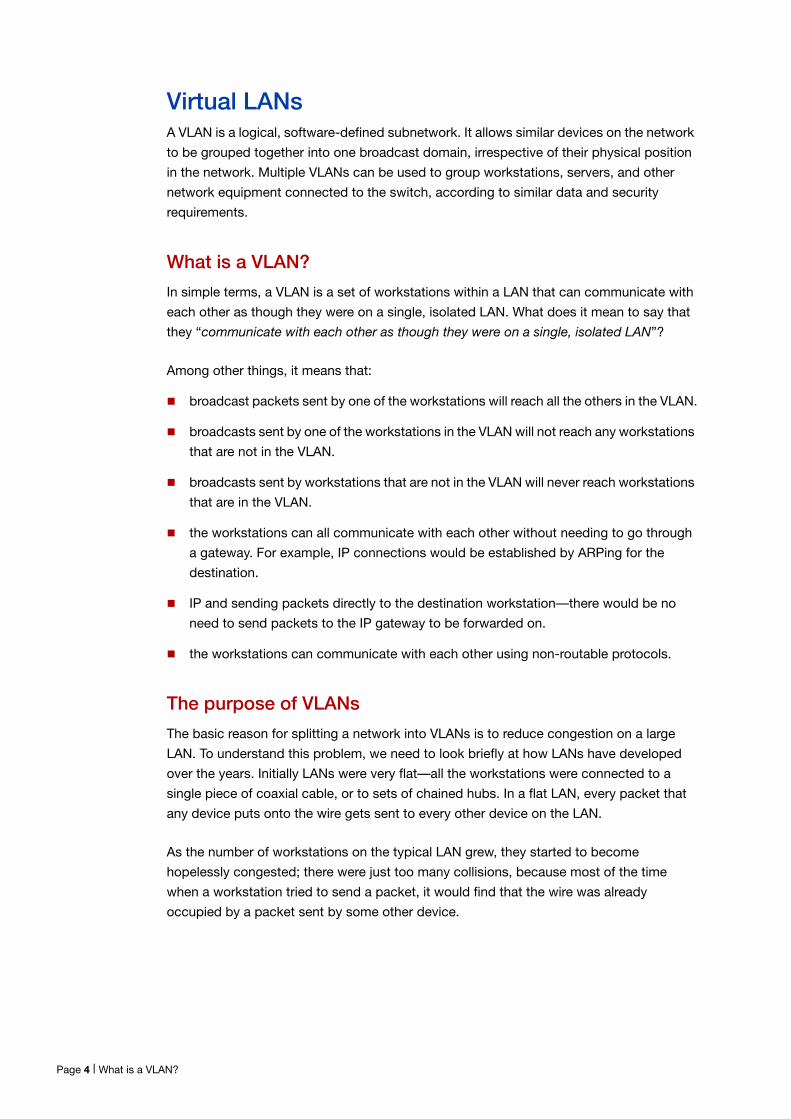
A simple switched network, though, still needs routers to set the boundaries of where
broadcasts are sent (referred to as “broadcast containment”). So, the typical LAN was set
up as shown below in Figure 1.
Figure 1: Typical VLAN
bridge orswitch
workstation
LAN segments(Collision Domains)
LAN(Broadcast Domain)
hub hub
bridge orswitch
router
hub hub
hub hub
Using routers to segment LANs | Page 5
Domain terminology
The above figure introduces the concept of a LAN segment. This is also referred to as a
collision domain, because when a device is trying to send a packet, it can only collide with
packets sent by other devices on the same segment. Each LAN segment consists of all
the devices attached to a single switch port—the switch stops packets from different
ports from colliding with each other.
The LAN itself is referred to as a broadcast domain, because if any device within the LAN
sends out a broadcast packet, it will be transmitted to all devices in that LAN, but not to
devices beyond the LAN.
Using VLANs to segment LANs
As LANs became larger, data rates became faster, and users desired greater flexibility, the
routers in a network started to become a bottleneck. This is because:
routers typically forward data in software, and so are not as fast as switches.
splitting up a LAN using routers meant that a LAN typically corresponded to a particular
physical location. This became limiting when many users had laptops, and wanted to
be able to move between buildings, but still have the same network environment
wherever they plugged in.
Switch vendors started implementing methods for defining “virtual LANs”—sets of switch
ports, usually distributed across multiple switches, that somehow interacted as though
they were in a single isolated LAN. This way, workstations could be separated off into
separate LANs without being physically divided up by routers.
At about the same time, hubs became less popular and have been largely replaced by L2
switches. This has made the whole concept of a collision domain somewhat historical. In
modern networks, a “collision domain” mostly consists of a single device attached to an
L2 switch port, or possibly a PC with something like an IP phone attached to it.
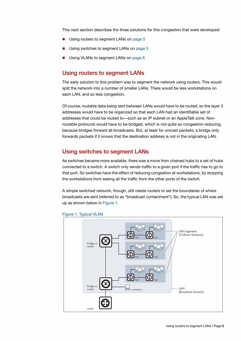
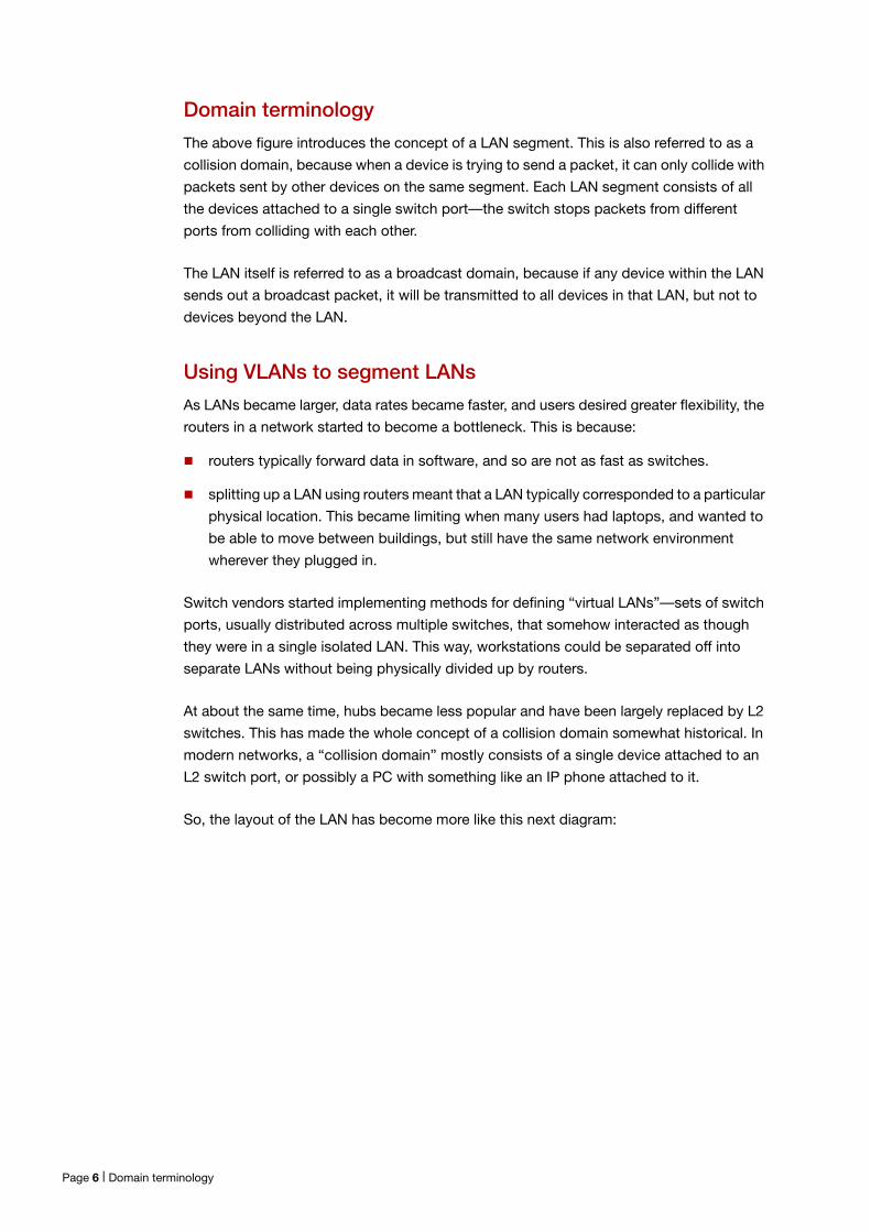
So, the layout of the LAN has become more like this next diagram:
Page 6 | Domain terminology
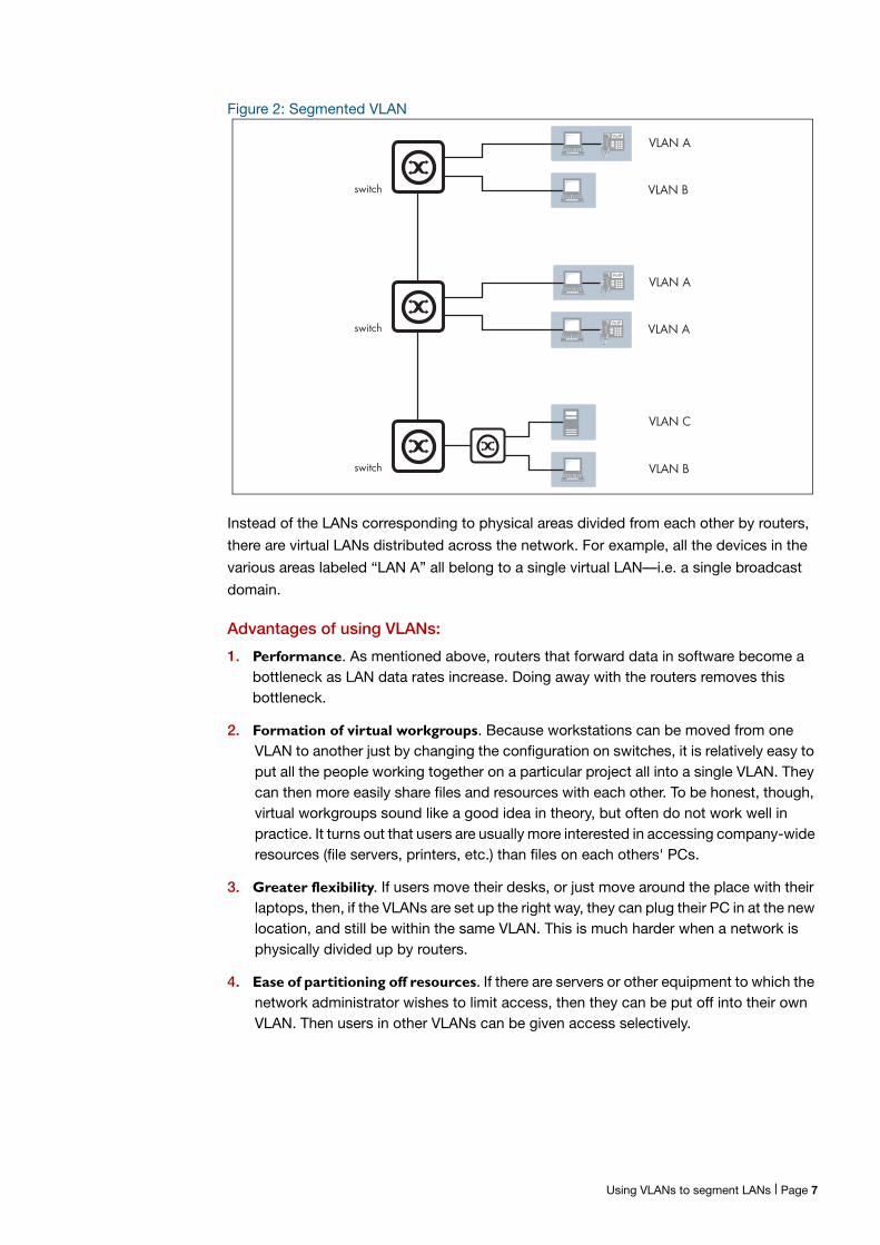
Figure 2: Segmented VLAN
Instead of the LANs corresponding to physical areas divided from each other by routers,
there are virtual LANs distributed across the network. For example, all the devices in the
various areas labeled “LAN A” all belong to a single virtual LAN—i.e. a single broadcast
domain.
Advantages of using VLANs:
1. Performance. As mentioned above, routers that forward data in software become a bottleneck as LAN data rates increase. Doing away with the routers removes this bottleneck.
2. Formation of virtual workgroups. Because workstations can be moved from one VLAN to another just by changing the configuration on switches, it is relatively easy to put all the people working together on a particular project all into a single VLAN. They can then more easily share files and resources with each other. To be honest, though, virtual workgroups sound like a good idea in theory, but often do not work well in practice. It turns out that users are usually more interested in accessing company-wide resources (file servers, printers, etc.) than files on each others' PCs.
3. Greater flexibility. If users move their desks, or just move around the place with their laptops, then, if the VLANs are set up the right way, they can plug their PC in at the new location, and still be within the same VLAN. This is much harder when a network is physically divided up by routers.
4. Ease of partitioning off resources. If there are servers or other equipment to which the network administrator wishes to limit access, then they can be put off into their own VLAN. Then users in other VLANs can be given access selectively.
VoIP
switch
switch
switch VLAN B
VLAN C
VLAN A
VLAN A
VoIP
VoIP
VLAN A
VLAN B
Using VLANs to segment LANs | Page 7
Implementing VLANs
Port-based VLANs
In the previous section, we simply stated that the network is split up into sets of virtual
LANs. It is one thing to say this, it is quite another thing to understand how this is actually
achieved.
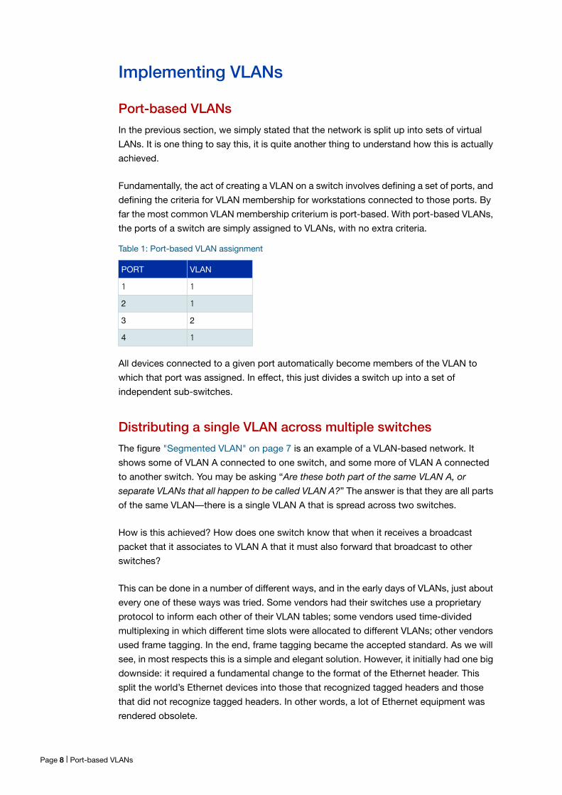
Fundamentally, the act of creating a VLAN on a switch involves defining a set of ports, and
defining the criteria for VLAN membership for workstations connected to those ports. By
far the most common VLAN membership criterium is port-based. With port-based VLANs,
the ports of a switch are simply assigned to VLANs, with no extra criteria.
All devices connected to a given port automatically become members of the VLAN to
which that port was assigned. In effect, this just divides a switch up into a set of
independent sub-switches.
Distributing a single VLAN across multiple switches
The figure "Segmented VLAN" on page 7 is an example of a VLAN-based network. It
shows some of VLAN A connected to one switch, and some more of VLAN A connected
to another switch. You may be asking “Are these both part of the same VLAN A, or
separate VLANs that all happen to be called VLAN A?” The answer is that they are all parts
of the same VLAN—there is a single VLAN A that is spread across two switches.
How is this achieved? How does one switch know that when it receives a broadcast
packet that it associates to VLAN A that it must also forward that broadcast to other
switches?
This can be done in a number of different ways, and in the early days of VLANs, just about
every one of these ways was tried. Some vendors had their switches use a proprietary
protocol to inform each other of their VLAN tables; some vendors used time-divided
multiplexing in which different time slots were allocated to different VLANs; other vendors
used frame tagging. In the end, frame tagging became the accepted standard. As we will
see, in most respects this is a simple and elegant solution. However, it initially had one big
downside: it required a fundamental change to the format of the Ethernet header. This
split the world’s Ethernet devices into those that recognized tagged headers and those
that did not recognize tagged headers. In other words, a lot of Ethernet equipment was
rendered obsolete.
Table 1: Port-based VLAN assignment
PORT VLAN
1 1
2 1
3 2
4 1
Page 8 | Port-based VLANs
How does tagging work?
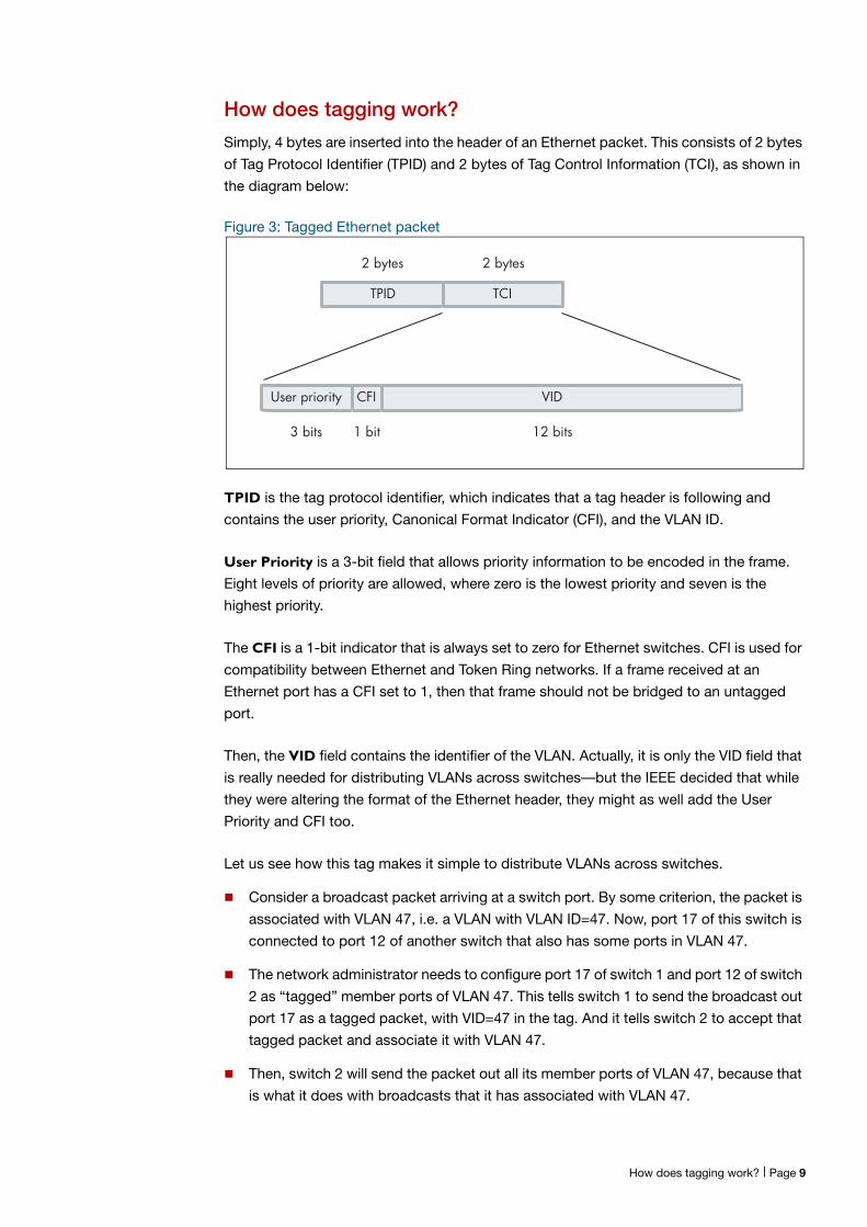
Simply, 4 bytes are inserted into the header of an Ethernet packet. This consists of 2 bytes
of Tag Protocol Identifier (TPID) and 2 bytes of Tag Control Information (TCI), as shown in
the diagram below:
Figure 3: Tagged Ethernet packet
TPID is the tag protocol identifier, which indicates that a tag header is following and
contains the user priority, Canonical Format Indicator (CFI), and the VLAN ID.
User Priority is a 3-bit field that allows priority information to be encoded in the frame.
Eight levels of priority are allowed, where zero is the lowest priority and seven is the
highest priority.
The CFI is a 1-bit indicator that is always set to zero for Ethernet switches. CFI is used for
compatibility between Ethernet and Token Ring networks. If a frame received at an
Ethernet port has a CFI set to 1, then that frame should not be bridged to an untagged
port.
Then, the VID field contains the identifier of the VLAN. Actually, it is only the VID field that
is really needed for distributing VLANs across switches—but the IEEE decided that while
they were altering the format of the Ethernet header, they might as well add the User
Priority and CFI too.
Let us see how this tag makes it simple to distribute VLANs across switches.
Consider a broadcast packet arriving at a switch port. By some criterion, the packet is
associated with VLAN 47, i.e. a VLAN with VLAN ID=47. Now, port 17 of this switch is
connected to port 12 of another switch that also has some ports in VLAN 47.
The network administrator needs to configure port 17 of switch 1 and port 12 of switch
2 as “tagged” member ports of VLAN 47. This tells switch 1 to send the broadcast out
port 17 as a tagged packet, with VID=47 in the tag. And it tells switch 2 to accept that
tagged packet and associate it with VLAN 47.
Then, switch 2 will send the packet out all its member ports of VLAN 47, because that
is what it does with broadcasts that it has associated with VLAN 47.
2 bytes2 bytes
TPID TCI
User priority CFI VID
3 bits 1 bit 12 bits
How does tagging work? | Page 9
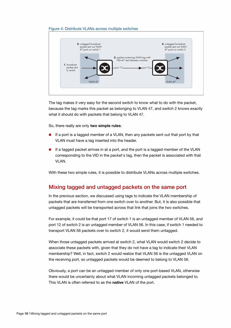
Figure 4: Distribute VLANs across multiple switches
The tag makes it very easy for the second switch to know what to do with the packet,
because the tag marks this packet as belonging to VLAN 47, and switch 2 knows exactly
what it should do with packets that belong to VLAN 47.
So, there really are only two simple rules:
If a port is a tagged member of a VLAN, then any packets sent out that port by that
VLAN must have a tag inserted into the header.
If a tagged packet arrives in at a port, and the port is a tagged member of the VLAN
corresponding to the VID in the packet's tag, then the packet is associated with that
VLAN.
With these two simple rules, it is possible to distribute VLANs across multiple switches.
Mixing tagged and untagged packets on the same port
In the previous section, we discussed using tags to indicate the VLAN membership of
packets that are transferred from one switch over to another. But, it is also possible that
untagged packets will be transported across that link that joins the two switches.
For example, it could be that port 17 of switch 1 is an untagged member of VLAN 56, and
port 12 of switch 2 is an untagged member of VLAN 56. In this case, if switch 1 needed to
transport VLAN 56 packets over to switch 2, it would send them untagged.
When those untagged packets arrived at switch 2, what VLAN would switch 2 decide to
associate these packets with, given that they do not have a tag to indicate their VLAN
membership? Well, in fact, switch 2 would realize that VLAN 56 is the untagged VLAN on
the receiving port, so untagged packets would be deemed to belong to VLAN 56.
Obviously, a port can be an untagged member of only one port-based VLAN, otherwise
there would be uncertainty about what VLAN incoming untagged packets belonged to.
This VLAN is often referred to as the native VLAN of the port.
VLAN 47
port 17 port 121. broadcast packet sent to switch
2. untagged broadcast packet sent out VLAN 47 ports on switch 1
3. packet containing VLAN tag with VID=47 sent between switches
VLAN 47
4. untagged broadcast packet sent out VLAN 47 ports on switch 2
Page 10 | Mixing tagged and untagged packets on the same port
Often, you might not want to associate a native VLAN with the port that connects a switch
to another switch, so that all packets coming into that port must use a VLAN tag to
indicate their VLAN membership. This stops the switch from accepting any untagged
packets on the port. In AlliedWare Plus, this is achieved by configuring a port to trunk
mode and not configuring a native VLAN on it. In AlliedWare, it is achieved by setting the
parameter acceptable=vlan on the port, so that the port will only accept VLAN-tagged
packets.
Only accepting packets that match the port’s VLAN configuration (ingress filtering)
Consider a port that is connected to a normal workstation. Normal applications on the
workstation will never send tagged packets, so there is no requirement for the switch port
to accept tagged packets.
But, is there any harm if the port does accept tagged packets if they happen to come
along? Well, the answer is “quite possibly yes”. If the workstation does send tagged
packets, then it is very likely doing so for malicious reasons.
To guard against such maliciousness, most switches provide the ability to configure
ingress filtering. When ingress filtering is applied to a port, packets will only be accepted
into a port if they match the VLAN configuration of that port. So, if the port is an untagged
member of one VLAN, and nothing else, then only untagged packets will be accepted on
the port. If the port is tagged for a set of VLANs, then a tagged packet will be accepted
into the port only if it is tagged with the VID of one of the tagged VLANs configured on the
port.
We highly recommend that you configure ingress filtering on all switch ports, because
there is seldom a good reason for a port to accept packets from VLANs that are not
configured on that port. Under AlliedWare Plus, ingress filtering is enabled on all ports by
default.
The switch passes VLAN status information to the Internet Protocol (IP) module that
indicates whether a VLAN is up or down. This information is used to determine route
availability.
The device supports up to 4094 VLANs (the maximum allowed by the VID field in the
802.1Q tag). On some devices a few of these VLANs may be reserved for management
purposes. When the switch is first powered up (and therefore unconfigured), it creates a
default VLAN with a VID of 1 and an interface name of vlan1. In this initial condition, the
switch attaches all its ports to this default VLAN.
The default VLAN cannot be deleted, and ports can only be removed from it if they also
belong to at least one other VLAN. If all the devices on the physical LAN belong to the
same logical LAN, that is, the same broadcast domain, then the default settings will be
acceptable, and no additional VLAN configuration is required.
Only accepting packets that match the port’s VLAN configuration (ingress filtering) | Page 11
Configuring VLANs
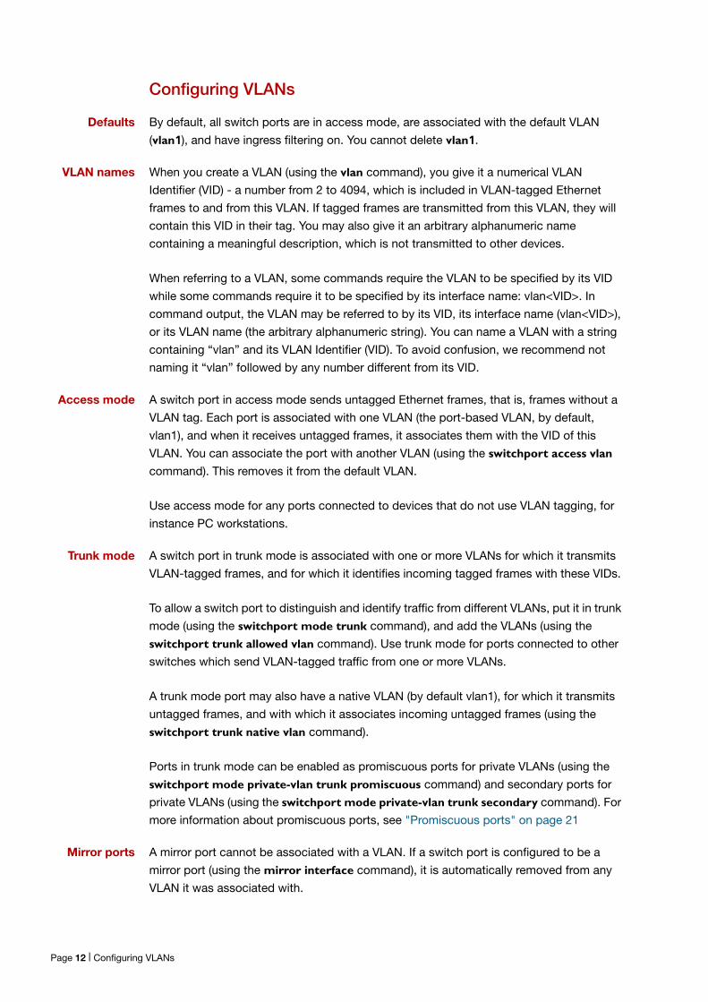
Defaults By default, all switch ports are in access mode, are associated with the default VLAN
(vlan1), and have ingress filtering on. You cannot delete vlan1.
VLAN names When you create a VLAN (using the vlan command), you give it a numerical VLAN
Identifier (VID) - a number from 2 to 4094, which is included in VLAN-tagged Ethernet
frames to and from this VLAN. If tagged frames are transmitted from this VLAN, they will
contain this VID in their tag. You may also give it an arbitrary alphanumeric name
containing a meaningful description, which is not transmitted to other devices.
When referring to a VLAN, some commands require the VLAN to be specified by its VID
while some commands require it to be specified by its interface name: vlan<VID>. In
command output, the VLAN may be referred to by its VID, its interface name (vlan<VID>),
or its VLAN name (the arbitrary alphanumeric string). You can name a VLAN with a string
containing “vlan” and its VLAN Identifier (VID). To avoid confusion, we recommend not
naming it “vlan” followed by any number different from its VID.
Access mode A switch port in access mode sends untagged Ethernet frames, that is, frames without a
VLAN tag. Each port is associated with one VLAN (the port-based VLAN, by default,
vlan1), and when it receives untagged frames, it associates them with the VID of this
VLAN. You can associate the port with another VLAN (using the switchport access vlan
command). This removes it from the default VLAN.
Use access mode for any ports connected to devices that do not use VLAN tagging, for
instance PC workstations.
Trunk mode A switch port in trunk mode is associated with one or more VLANs for which it transmits
VLAN-tagged frames, and for which it identifies incoming tagged frames with these VIDs.
To allow a switch port to distinguish and identify traffic from different VLANs, put it in trunk
mode (using the switchport mode trunk command), and add the VLANs (using the
switchport trunk allowed vlan command). Use trunk mode for ports connected to other
switches which send VLAN-tagged traffic from one or more VLANs.
A trunk mode port may also have a native VLAN (by default vlan1), for which it transmits
untagged frames, and with which it associates incoming untagged frames (using the
switchport trunk native vlan command).
Ports in trunk mode can be enabled as promiscuous ports for private VLANs (using the
switchport mode private-vlan trunk promiscuous command) and secondary ports for
private VLANs (using the switchport mode private-vlan trunk secondary command). For
more information about promiscuous ports, see "Promiscuous ports" on page 21
Mirror ports A mirror port cannot be associated with a VLAN. If a switch port is configured to be a
mirror port (using the mirror interface command), it is automatically removed from any
VLAN it was associated with.
Page 12 | Configuring VLANs
VLANs and channel groups
All the ports in a channel group must have the same VLAN configuration: they must
belong to the same VLANs and have the same tagging status, and can only be operated
on as a group.
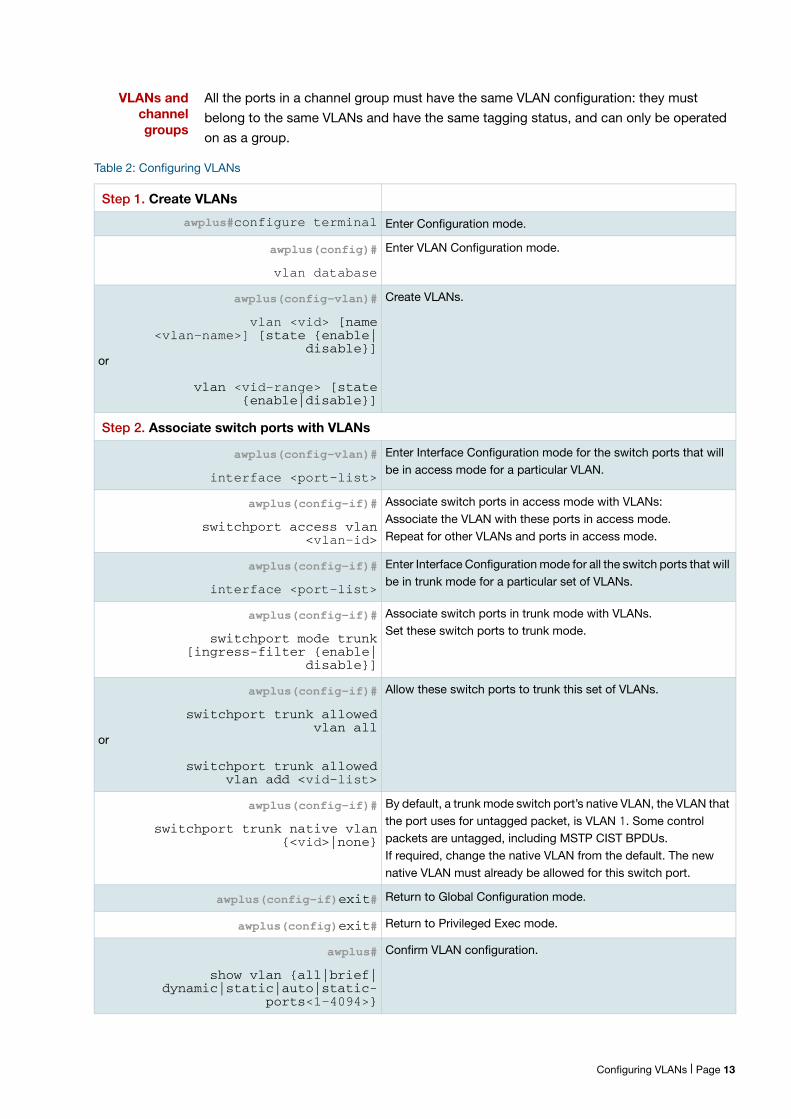
Table 2: Configuring VLANs
Step 1. Create VLANs
awplus#configure terminal Enter Configuration mode.
awplus(config)#
vlan database
Enter VLAN Configuration mode.
awplus(config-vlan)#
vlan <vid> [name <vlan-name>] [state {enable|
disable}]or
vlan <vid-range> [state {enable|disable}]
Create VLANs.
Step 2. Associate switch ports with VLANs
awplus(config-vlan)#
interface <port-list>
Enter Interface Configuration mode for the switch ports that will be in access mode for a particular VLAN.
awplus(config-if)#
switchport access vlan <vlan-id>
Associate switch ports in access mode with VLANs:Associate the VLAN with these ports in access mode.Repeat for other VLANs and ports in access mode.
awplus(config-if)#
interface <port-list>
Enter Interface Configuration mode for all the switch ports that will be in trunk mode for a particular set of VLANs.
awplus(config-if)#
switchport mode trunk [ingress-filter {enable|
disable}]
Associate switch ports in trunk mode with VLANs.Set these switch ports to trunk mode.
awplus(config-if)#
switchport trunk allowed vlan all
or
switchport trunk allowed vlan add <vid-list>
Allow these switch ports to trunk this set of VLANs.
awplus(config-if)#
switchport trunk native vlan {<vid>|none}
By default, a trunk mode switch port’s native VLAN, the VLAN that the port uses for untagged packet, is VLAN 1. Some control packets are untagged, including MSTP CIST BPDUs.If required, change the native VLAN from the default. The new native VLAN must already be allowed for this switch port.
awplus(config-if)exit# Return to Global Configuration mode.
awplus(config)exit# Return to Privileged Exec mode.
awplus#
show vlan {all|brief|dynamic|static|auto|static-
ports<1-4094>}
Confirm VLAN configuration.
Configuring VLANs | Page 13
VLAN Double Tagging (VLAN Stacking)Double tagged VLANs are used to overlay a private Layer 2 network over a public Layer 2
network. The feature is also known as Nested VLANs, VLAN stacking, and Q-in-Q. It
provides a method of transporting different clients' traffic across a shared Ethernet infrastructure.
Network service providers often have customers whose VLAN IDs overlap, therefore, a solution is required to control each client's traffic when the traffic from different clients is mixed together within the service providers' infrastructure, (i.e. different customers will allocate the same VIDs to their VLANs). With a nested VLAN configuration, each customer
is given a customer-ID (S-Tag), which is a unique identifier within the service provider
infrastructure. Traffic from individual customers is tagged with the S-Tag and segregated
from other customer’s traffic. The VLAN identification of the customer’s network can be
preserved while the traffic is tunneled through the network service provider’s
infrastructure. You may need a special feature licence to use nested VLANs. See your
Allied Telesis distributor or reseller for more information.
How double-tagged VLANs work
In a nested VLAN environment VLAN tagging exists at two levels:
client tagging (C-tag)
service provider tagging (S-tag)
When nested VLAN functionality is enabled, the service provider assigns to each of its
clients an individual 12 bit customer VID called an S-tag. The S-tag field has an identical
structure to the VLAN tag field.
The switch that performs the double tagging has two sets of specially designated ports:
Customer edge ports —that face the customer networks from which single-tagged
packets are arriving.
Provider ports (or Core ports)— that connect into the service provider infrastructure, on
which double-tagged packets are arriving and leaving.
A customer edge port will always be a member of ONE service provider VLAN. A provider
port can be a member of multiple service provider VLANs. Packets entering the customer
port of the service provider switch are VLAN tagged packets with original VLAN identifiers
(C-tag VIDs) from the customer network. When the packets enter the switch via a
customer edge port, the switch adds an S-tag (outer tag) on top of the C-tag (inner tag). If
the packet was originally untagged, then the S-tag becomes the packets one and only
tag. Within the service provider infrastructure, the C-tag (inner tag) is ignored and bridging
is based on the value of the S-tag. When the S-tag tagged packets exit the service
provider network via a customer edge port of the destination switch, the S-tag (outer tag)
is removed. Therefore, when the packets exit the customer port, the original VLAN tags
are preserved.
Page 14 | How double-tagged VLANs work
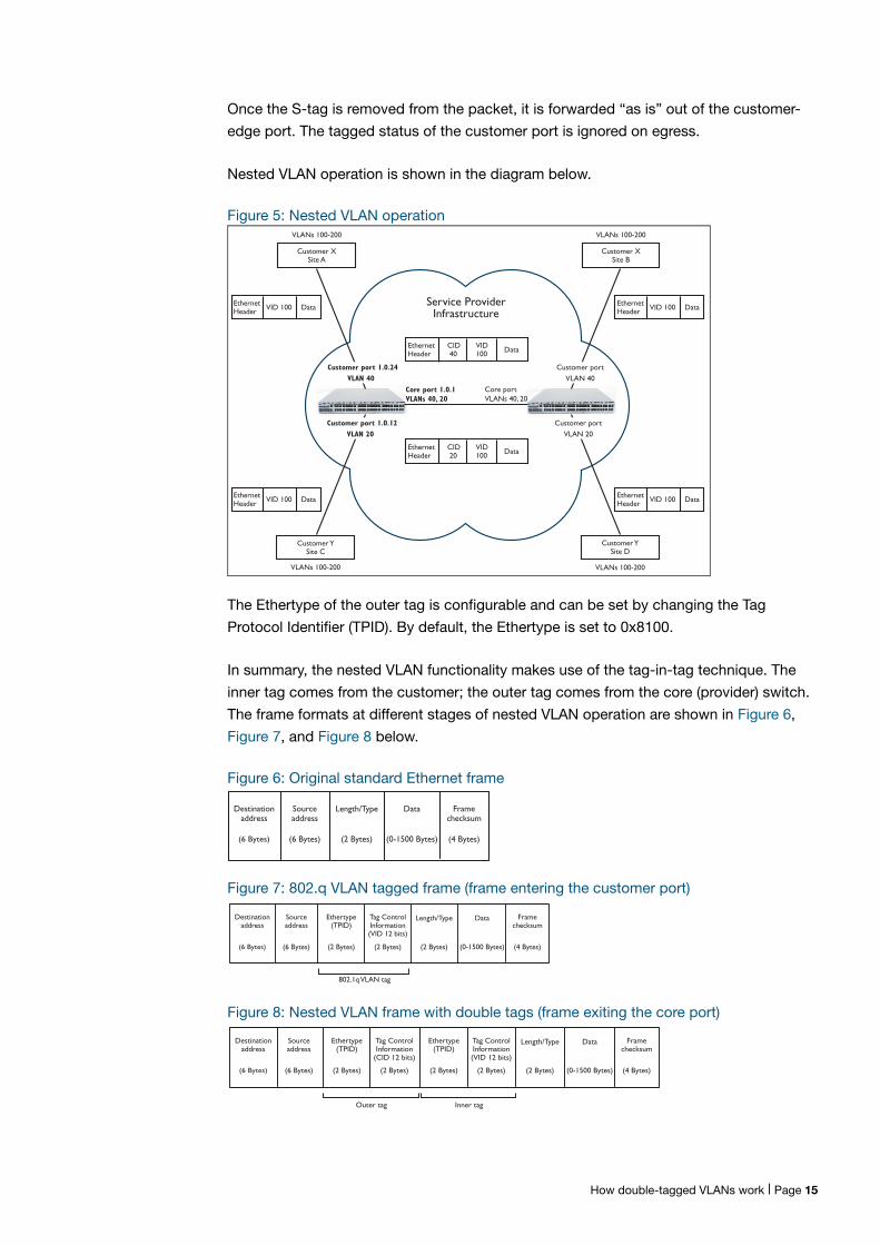
Once the S-tag is removed from the packet, it is forwarded “as is” out of the customer-
edge port. The tagged status of the customer port is ignored on egress.
Nested VLAN operation is shown in the diagram below.
Figure 5: Nested VLAN operation
The Ethertype of the outer tag is configurable and can be set by changing the Tag
Protocol Identifier (TPID). By default, the Ethertype is set to 0x8100.
In summary, the nested VLAN functionality makes use of the tag-in-tag technique. The
inner tag comes from the customer; the outer tag comes from the core (provider) switch.
The frame formats at different stages of nested VLAN operation are shown in Figure 6,
Figure 7, and Figure 8 below.
Figure 6: Original standard Ethernet frame
Figure 7: 802.q VLAN tagged frame (frame entering the customer port)
Figure 8: Nested VLAN frame with double tags (frame exiting the core port)
VLANs 100-200
Customer YSite C
EthernetHeader VID 100 Data
EthernetHeader
CID 20
VID100 Data
Customer port 1.0.24VLAN 40
Service Provider Infrastructure
Core port 1.0.1VLANs 40, 20
Core portVLANs 40, 20
EthernetHeader VID 100 DataEthernet
Header VID 100 Data
EthernetHeader VID 100 Data
Customer portVLAN 20
Customer port 1.0.12VLAN 20
Customer portVLAN 40
VLANs 100-200
Customer YSite D
VLANs 100-200
Customer XSite B
VLANs 100-200
Customer XSite A
EthernetHeader
CID 40
VID100 Data
Destinationaddress
(6 Bytes)
Sourceaddress
(6 Bytes)
Length/Type
(2 Bytes)
Data
(0-1500 Bytes) (4 Bytes)
Framechecksum
Ethertype(TPID)
Tag ControlInformation(VID 12 bits)
(2 Bytes)(2 Bytes)
802.1q VLAN tag
Destinationaddress
(6 Bytes)
Sourceaddress
(6 Bytes)
Length/Type
(2 Bytes)
Data
(0-1500 Bytes) (4 Bytes)
Framechecksum
Ethertype(TPID)
Tag ControlInformation
(CID 12 bits)
(2 Bytes)(2 Bytes)
Outer tag Inner tag
Ethertype(TPID)
Tag ControlInformation(VID 12 bits)
(2 Bytes)(2 Bytes)
Destinationaddress
(6 Bytes)
Sourceaddress
(6 Bytes)
Length/Type
(2 Bytes)
Data
(0-1500 Bytes) (4 Bytes)
Framechecksum
How double-tagged VLANs work | Page 15
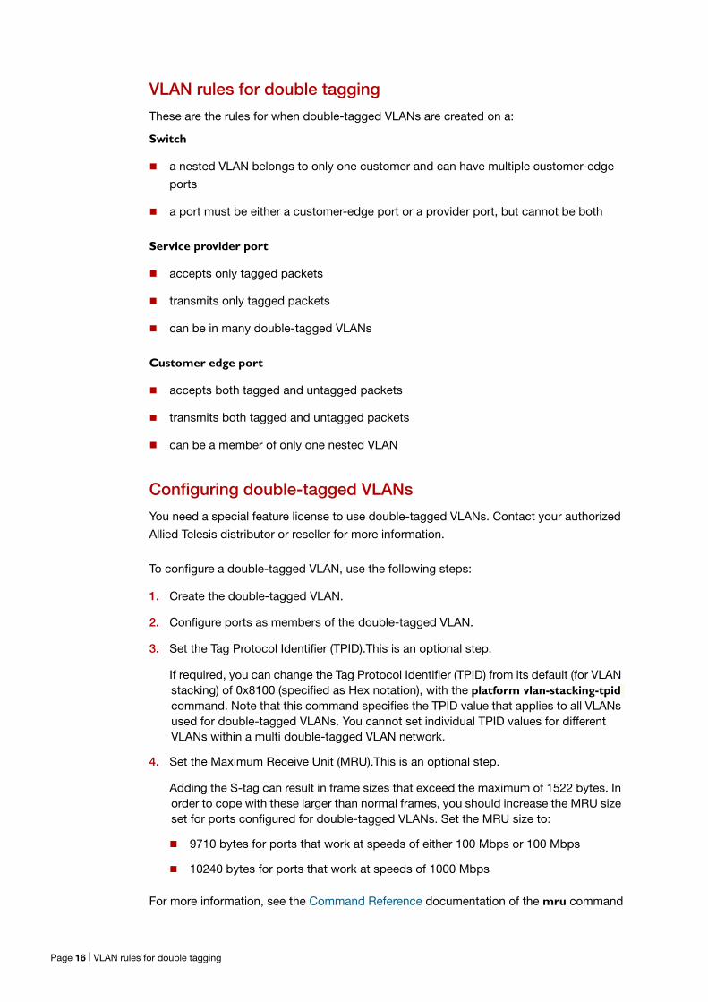
VLAN rules for double tagging
These are the rules for when double-tagged VLANs are created on a:
Switch
a nested VLAN belongs to only one customer and can have multiple customer-edge
ports
a port must be either a customer-edge port or a provider port, but cannot be both
Service provider port
accepts only tagged packets
transmits only tagged packets
can be in many double-tagged VLANs
Customer edge port
accepts both tagged and untagged packets
transmits both tagged and untagged packets
can be a member of only one nested VLAN
Configuring double-tagged VLANs
You need a special feature license to use double-tagged VLANs. Contact your authorized
Allied Telesis distributor or reseller for more information.
To configure a double-tagged VLAN, use the following steps:
1. Create the double-tagged VLAN.
2. Configure ports as members of the double-tagged VLAN.
3. Set the Tag Protocol Identifier (TPID).This is an optional step.
If required, you can change the Tag Protocol Identifier (TPID) from its default (for VLAN stacking) of 0x8100 (specified as Hex notation), with the platform vlan-stacking-tpid command. Note that this command specifies the TPID value that applies to all VLANs used for double-tagged VLANs. You cannot set individual TPID values for different VLANs within a multi double-tagged VLAN network.
4. Set the Maximum Receive Unit (MRU).This is an optional step.
Adding the S-tag can result in frame sizes that exceed the maximum of 1522 bytes. In order to cope with these larger than normal frames, you should increase the MRU size set for ports configured for double-tagged VLANs. Set the MRU size to:
9710 bytes for ports that work at speeds of either 100 Mbps or 100 Mbps
10240 bytes for ports that work at speeds of 1000 Mbps
For more information, see the Command Reference documentation of the mru command
Page 16 | VLAN rules for double tagging
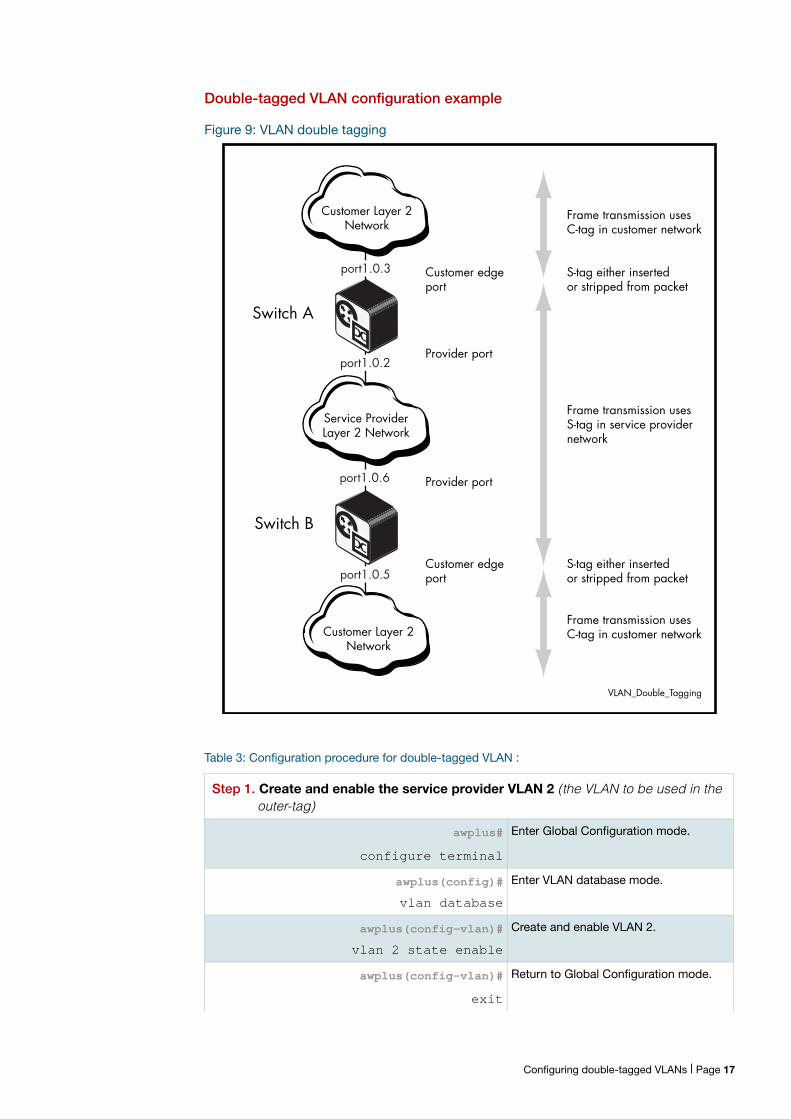
Double-tagged VLAN configuration example
Figure 9: VLAN double tagging
Table 3: Configuration procedure for double-tagged VLAN :
Step 1. Create and enable the service provider VLAN 2 (the VLAN to be used in the outer-tag)
awplus#
configure terminal
Enter Global Configuration mode.
awplus(config)#
vlan database
Enter VLAN database mode.
awplus(config-vlan)#
vlan 2 state enable
Create and enable VLAN 2.
awplus(config-vlan)#
exit
Return to Global Configuration mode.
Customer Layer 2Network
Service ProviderLayer 2 Network
Customer Layer 2Network
Switch A
Switch B
port1.0.2
port1.0.3
port1.0.6
port1.0.5
Provider port
Provider port
Customer edgeport
Customer edgeport
VLAN_Double_Tagging
Frame transmission usesC-tag in customer network
S-tag either insertedor stripped from packet
S-tag either insertedor stripped from packet
Frame transmission usesS-tag in service providernetwork
Frame transmission usesC-tag in customer network
Configuring double-tagged VLANs | Page 17
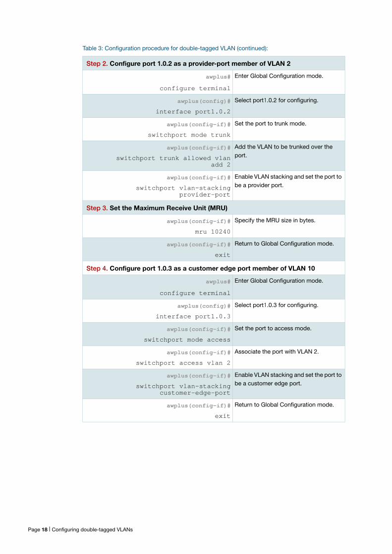
Step 2. Configure port 1.0.2 as a provider-port member of VLAN 2
awplus#
configure terminal
Enter Global Configuration mode.
awplus(config)#
interface port1.0.2
Select port1.0.2 for configuring.
awplus(config-if)#
switchport mode trunk
Set the port to trunk mode.
awplus(config-if)#
switchport trunk allowed vlan add 2
Add the VLAN to be trunked over the port.
awplus(config-if)#
switchport vlan-stacking provider-port
Enable VLAN stacking and set the port to be a provider port.
Step 3. Set the Maximum Receive Unit (MRU)
awplus(config-if)#
mru 10240
Specify the MRU size in bytes.
awplus(config-if)#
exit
Return to Global Configuration mode.
Step 4. Configure port 1.0.3 as a customer edge port member of VLAN 10
awplus#
configure terminal
Enter Global Configuration mode.
awplus(config)#
interface port1.0.3
Select port1.0.3 for configuring.
awplus(config-if)#
switchport mode access
Set the port to access mode.
awplus(config-if)#
switchport access vlan 2
Associate the port with VLAN 2.
awplus(config-if)#
switchport vlan-stacking customer-edge-port
Enable VLAN stacking and set the port to be a customer edge port.
awplus(config-if)#
exit
Return to Global Configuration mode.
Table 3: Configuration procedure for double-tagged VLAN (continued):
Page 18 | Configuring double-tagged VLANs
Private VLANsPrivate VLANs are VLANs with additional rules.These rules limit the communication that is
possible between devices operating within the VLAN. This may be necessary for security
reasons. AlliedWare Plus private VLANs provide the ability to divide a VLAN’s ports into
separate “groups” and to allow communication within any individual group, but not
between groups.
A group can be any number of ports or a single port. Private VLANs combine the network
advantages of conventional VLANs, with an added degree of privacy obtained by limiting
the connectivity between selected ports.
This section provides an introduction to:
Private VLANs for ports in access mode
Private VLANs for trunked ports
Private VLAN functionality allows your network administrator greater control over the
information end users may access on the LAN.
On public networks in particular, users can be vulnerable to attack from other users on the
same LAN. In addition, there is typically no real need for these users to be able to
communicate directly to one another. A private VLAN is a sensible solution. It creates a
situation where users are isolated from each other, and are only able to exchange packets
with ports that connect to the upstream network.
Some typical scenarios that would benefit from private VLANs include:
Hotels
Universities, particularly student accommodation
Libraries
Internet cafés
Hospitals
Multi Dwelling Unit Internet access via a shared LAN
An example application of a private VLAN would be a library in which user booths each
have a PC with Internet access. In this situation it would usually be undesirable to allow
communication between these individual PCs. Connecting the PC to ports within a private
isolated VLAN would enable each PC to access the Internet or a library server via a single
connection, whilst preventing access between the PCs in the booths.
Another application might be to use private VLANs to simplify IP address assignment.
Ports can be isolated from each other whilst still belonging to the same subnet.
Configuring double-tagged VLANs | Page 19
AlliedWare Plus private VLAN solutions
AlliedWare Plus has two private VLAN solutions:
Private VLANs for ports in Access Mode
Private VLANs for ports in Trunked Mode
Private VLANs for ports in Access Mode are based on the industry standard which have
the following features:
Primary and secondary VLANs
Isolated and community ports are used in the secondary VLANs
No trunked ports
Private VLANs for ports in Trunked Mode have the following features:
One isolated VLAN
No community ports or VLANs
Both the promiscuous and secondary ports are trunked members of the VLAN
Private VLANs for Ports in Access ModeThis type of private VLAN is actually a set of associated VLANs. This set consists of one
Primary VLAN, and one or more Secondary VLANs.
Primary VLAN
The Primary VLAN is the main VLAN.
The Secondary VLANs in the associated set use the Primary VLAN to communicate to the
rest of the network. In this way, it functions as the “front” VLAN. The Primary VLAN
contains the promiscuous port, which carries the private VLAN traffic to and from the rest
of the network. The promiscuous port is explained in further detail below.
Secondary VLANs
There are two types of Secondary VLANs:
Community VLAN - Ports within a Community VLAN can communicate with each other,
as well as with the promiscuous port. Within a Community VLAN, the normal Layer2
switching functionality applies - flooding of broadcast, multicast and unknown unicast
packets occurs, just as in a standard VLAN.
Isolated VLAN - The ports in an Isolated VLAN are only allowed to communicate via the
promiscuous port. Note that ports within different Secondary VLANs cannot
communicate with each other.
Page 20 | AlliedWare Plus private VLAN solutions
Membership rules for private VLANs in access mode
The following membership rules apply when creating and operating private VLANs in
access mode.
Each private VLAN:
must contain one promiscuous port (or aggregated link)
may contain multiple host ports
can be configured to span switch instances
can only contain promiscuous and host ports
cannot use the default VLAN (vlan1)
a private isolated VLAN can only contain a single promiscuous port
a private community VLAN can contain more than one promiscuous port
A promiscuous port:
is a member of the primary VLAN and all its associated secondary VLANs
cannot be a member of both private and non-private VLANs
A host port:
can be a member of multiple private (community) VLANs, but all these VLANs must
share the same promiscuous port
cannot be a host port in some VLANs and a non-host port in others
cannot be a promiscuous port in another VLAN
Promiscuous ports
A promiscuous port (also known as the uplink port), is the one port that can communicate
with all ports that are members of its associated secondary VLANs. Multiple promiscuous
ports can exist in a primary VLAN, but only if the primary VLAN is only associated with
community VLANS (that is, that there are no isolated VLANs associated with this primary
VLAN).
A promiscuous port is a member of the primary VLAN and all associated secondary
VLANs. Its Port VID is set to the VLAN ID of the primary VLAN.
The switch should always use the promiscuous port to connect to the rest of the network.
To configure a promiscuous port, use the following commands:
awplus# conf t
awplus(config)# int port1.0.1
awplus(config-if)# switchport mode private-VLAN promiscuous
Membership rules for private VLANs in access mode | Page 21
Host ports
All the ports in the private VLAN, other than the Promiscuous Port(s), are referred to as
host ports. All host ports are members of the Primary VLAN, and of one Secondary
VLANs. The PVID of a host port is the VLAN ID of the Secondary VLAN it belongs to.
Host ports have two levels of connectivity depending on whether they exist in an isolated
or a community VLAN:
1. Host ports within an isolated VLAN
These ports are only allowed to communicate with their VLAN’s promiscuous port, even
though they share their secondary (isolated) VLAN with other hosts. The host ports receive
their data from the promiscuous port via the primary VLAN, and individually transmit their
data to the promiscuous port via their common secondary VLAN.
2. Host ports within a community VLAN
These ports are able to communicate with both the promiscuous port and the other ports
within the community VLAN that they are associated with. They receive their data from the
promiscuous port via the primary VLAN, and transmit their data to both the promiscuous
port and the other host ports (within their community VLAN) via their common secondary
VLAN. However, the only external path from a community VLAN is from its promiscuous
port.
Page 22 | Host ports
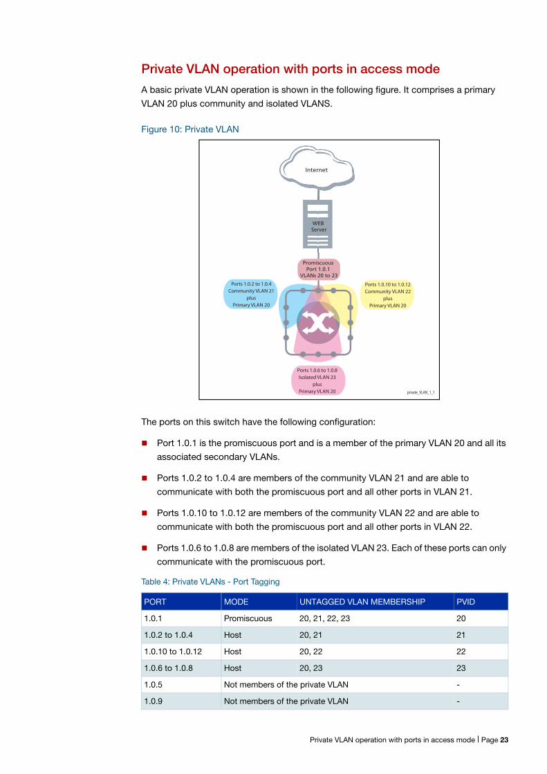
Private VLAN operation with ports in access mode
A basic private VLAN operation is shown in the following figure. It comprises a primary
VLAN 20 plus community and isolated VLANS.
Figure 10: Private VLAN
The ports on this switch have the following configuration:
Port 1.0.1 is the promiscuous port and is a member of the primary VLAN 20 and all its
associated secondary VLANs.
Ports 1.0.2 to 1.0.4 are members of the community VLAN 21 and are able to
communicate with both the promiscuous port and all other ports in VLAN 21.
Ports 1.0.10 to 1.0.12 are members of the community VLAN 22 and are able to
communicate with both the promiscuous port and all other ports in VLAN 22.
Ports 1.0.6 to 1.0.8 are members of the isolated VLAN 23. Each of these ports can only
communicate with the promiscuous port.
Table 4: Private VLANs - Port Tagging
PORT MODE UNTAGGED VLAN MEMBERSHIP PVID
1.0.1 Promiscuous 20, 21, 22, 23 20
1.0.2 to 1.0.4 Host 20, 21 21
1.0.10 to 1.0.12 Host 20, 22 22
1.0.6 to 1.0.8 Host 20, 23 23
1.0.5 Not members of the private VLAN -
1.0.9 Not members of the private VLAN -
private_VLAN_1_1
Internet
WEB Server
Ports 1.0.2 to 1.0.4Community VLAN 21
plusPrimary VLAN 20
Ports 1.0.10 to 1.0.12Community VLAN 22
plusPrimary VLAN 20
Ports 1.0.6 to 1.0.8Isolated VLAN 23
plusPrimary VLAN 20
Promiscuous Port 1.0.1
VLANs 20 to 23
Private VLAN operation with ports in access mode | Page 23
Private VLANs operate within a single switch and comprise one primary VLAN plus a
number of secondary VLANS. All data enters the private VLAN ports untagged.
Using the example of Figure 10 on page 23, data enters the switch via the promiscuous
port1.0.1 and is forwarded to the host ports using VLAN 20, the primary VLAN. Data
returning from the host ports to the promiscuous port (and exiting the switch) use the
secondary VLAN associated with its particular host port, VLAN 21, 22, or 23 in the
example.
Thus the data flows into the switch via the primary VLAN and out of the switch via the
secondary VLANs. This situation is not detected outside of the switch, because all its
private ports are untagged. Note however, that data flowing between ports within the
same community VLAN will do so using the VID of the community VLAN.
Portfast on private VLANS
Within private VLANs, we recommend that you place all host ports into spanning-tree
portfast mode and enable BPDU guard. Portfast assumes that because host ports will
also be edge ports, they will have no alternative paths (loops) via other bridges. These
ports are therefore allowed to move directly from the spanning-tree blocking state into the
forwarding state, thus bypassing the intermediate states.
Applying BPDU guard is an extra precaution. This feature disables an edge port if it
receives a BPDU frame, because receiving such a frame would indicate that the port has a
connection to another network bridge.
For more information on BPDU guard and portfast, refer to the following commands in the
CLI reference documentation:
spanning-tree portfast bpdu-guard
spanning-tree portfast (STP)
Configuration restrictions
you cannot configure the default VLAN (vlan1) as a private VLAN.
there can only be one Isolated VLAN associated with the Primary VLAN.
there can be multiple Community VLANs associated with the Primary VLAN.
Page 24 | Private VLAN operation with ports in access mode
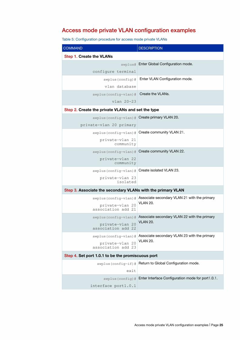
Access mode private VLAN configuration examples
Table 5: Configuration procedure for access mode private VLANs
COMMAND DESCRIPTION
Step 1. Create the VLANs
awplus#
configure terminal
Enter Global Configuration mode.
awplus(config)#
vlan database
Enter VLAN Configuration mode.
awplus(config-vlan)#
vlan 20-23
Create the VLANs.
Step 2. Create the private VLANs and set the type
awplus(config-vlan)#
private-vlan 20 primary
Create primary VLAN 20.
awplus(config-vlan)#
private-vlan 21 community
Create community VLAN 21.
awplus(config-vlan)#
private-vlan 22 community
Create community VLAN 22.
awplus(config-vlan)#
private-vlan 23 isolated
Create isolated VLAN 23.
Step 3. Associate the secondary VLANs with the primary VLAN
awplus(config-vlan)#
private-vlan 20 association add 21
Associate secondary VLAN 21 with the primary VLAN 20.
awplus(config-vlan)#
private-vlan 20 association add 22
Associate secondary VLAN 22 with the primary VLAN 20.
awplus(config-vlan)#
private-vlan 20 association add 23
Associate secondary VLAN 23 with the primary VLAN 20.
Step 4. Set port 1.0.1 to be the promiscuous port
awplus(config-if)#
exit
Return to Global Configuration mode.
awplus(config)#
interface port1.0.1
Enter Interface Configuration mode for port1.0.1.
Access mode private VLAN configuration examples | Page 25
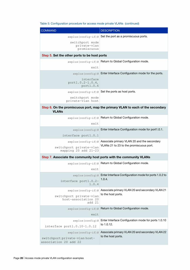
awplus(config-if)#
switchport mode private-vlan promiscuous
Set the port as a promiscuous ports.
Step 5. Set the other ports to be host ports
awplus(config-if)#
exit
Return to Global Configuration mode.
awplus(config)#
interface port1.0.2-1.0.4,
port1.0.6
Enter Interface Configuration mode for the ports.
awplus(config-if)#
switchport mode private-vlan host
Set the ports as host ports.
Step 6. On the promiscuous port, map the primary VLAN to each of the secondary VLANs
awplus(config-if)#
exit
Return to Global Configuration mode.
awplus(config)#
interface port1.0.1
Enter Interface Configuration mode for port1.0.1.
awplus(config-if)#
switchport private-vlan mapping 20 add 21-23
Associate primary VLAN 20 and the secondary VLANs 21 to 23 to the promiscuous port.
Step 7. Associate the community host ports with the community VLANs
awplus(config-if)#
exit
Return to Global Configuration mode.
awplus(config)#
interface port1.0.2-1.0.4
Enter Interface Configuration mode for ports 1.0.2 to 1.0.4.
awplus(config-if)#
switchport private-vlan host-association 20
add 21
Associate primary VLAN 20 and secondary VLAN 21 to the host ports.
awplus(config-if)#
exit
Return to Global Configuration mode.
awplus(config)#
interface port1.0.10-1.0.12
Enter Interface Configuration mode for ports 1.0.10 to 1.0.12.
awplus(config-if)#
switchport private-vlan host- association 20 add 22
Associate primary VLAN 20 and secondary VLAN 22 to the host ports.
Table 5: Configuration procedure for access mode private VLANs (continued)
COMMAND DESCRIPTION
Page 26 | Access mode private VLAN configuration examples
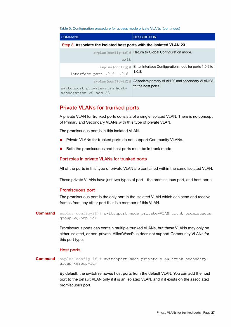
Private VLANs for trunked ports
A private VLAN for trunked ports consists of a single Isolated VLAN. There is no concept
of Primary and Secondary VLANs with this type of private VLAN.
The promiscuous port is in this Isolated VLAN.
Private VLANs for trunked ports do not support Community VLANs.
Both the promiscuous and host ports must be in trunk mode
Port roles in private VLANs for trunked ports
All of the ports in this type of private VLAN are contained within the same Isolated VLAN.
These private VLANs have just two types of port—the promiscuous port, and host ports.
Promiscuous port
The promiscuous port is the only port in the Isolated VLAN which can send and receive
frames from any other port that is a member of this VLAN.
Command awplus(config-if)# switchport mode private-VLAN trunk promiscuous group <group-id>
Promiscuous ports can contain multiple trunked VLANs, but these VLANs may only be
either isolated, or non-private. AlliedWarePlus does not support Community VLANs for
this port type.
Host ports
Command awplus(config-if)# switchport mode private-VLAN trunk secondary group <group-id>
By default, the switch removes host ports from the default VLAN. You can add the host
port to the default VLAN only if it is an Isolated VLAN, and if it exists on the associated
promiscuous port.
Step 8. Associate the isolated host ports with the isolated VLAN 23
awplus(config-if)#
exit
Return to Global Configuration mode.
awplus(config)#
interface port1.0.6-1.0.8
Enter Interface Configuration mode for ports 1.0.6 to 1.0.8.
awplus(config-if)#
switchport private-vlan host- association 20 add 23
Associate primary VLAN 20 and secondary VLAN 23 to the host ports.
Table 5: Configuration procedure for access mode private VLANs (continued)
COMMAND DESCRIPTION
Private VLANs for trunked ports | Page 27
The promiscuous port can be a member of multiple Isolated VLANs.
If a host port is a member of multiple Isolated VLANs, then the host port’s promiscuous
port must be the promiscuous port for all of these Isolated VLANs
A promiscuous port in trunk mode allows you to combine multiple isolated VLANs on a
single trunk port. A port in trunk mode enabled as a secondary port with the switchport
mode private-vlan trunk secondary command can combine traffic for multiple isolated
VLANs over a trunk.
A private VLAN group for trunked ports comprises the following components:
a single promiscuous port.
one or more isolated secondary (host) ports: These can only communicate with the
associated promiscuous port.
The following membership rules apply when creating and operating private VLANs for
trunked ports.
A promiscuous trunk port:
must be in trunk mode.
can be a member of both private VLANs and non-private VLANs.
has a group ID that is solely used to associate the promiscuous port with secondary
ports.
A secondary trunk port:
must be in trunk mode.
can only be a member of private VLANs.
cannot be a promiscuous port in another VLAN.
has a group ID that is solely used to associate the secondary port with its promiscuous
port.
Page 28 | Private VLANs for trunked ports
Trunked port private VLAN configuration example
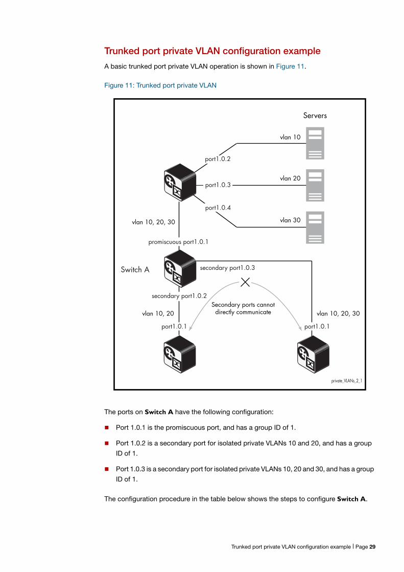
A basic trunked port private VLAN operation is shown in Figure 11.
Figure 11: Trunked port private VLAN
The ports on Switch A have the following configuration:
Port 1.0.1 is the promiscuous port, and has a group ID of 1.
Port 1.0.2 is a secondary port for isolated private VLANs 10 and 20, and has a group
ID of 1.
Port 1.0.3 is a secondary port for isolated private VLANs 10, 20 and 30, and has a group
ID of 1.
The configuration procedure in the table below shows the steps to configure Switch A.
private_VLANs_2_1
secondary port1.0.2
port1.0.2
port1.0.3
port1.0.4
Servers
vlan 10
vlan 20
vlan 30
promiscuous port1.0.1
Switch A secondary port1.0.3
vlan 10, 20 vlan 10, 20, 30
port1.0.1 port1.0.1
vlan 10, 20, 30
Secondary ports cannot directly communicate
Trunked port private VLAN configuration example | Page 29
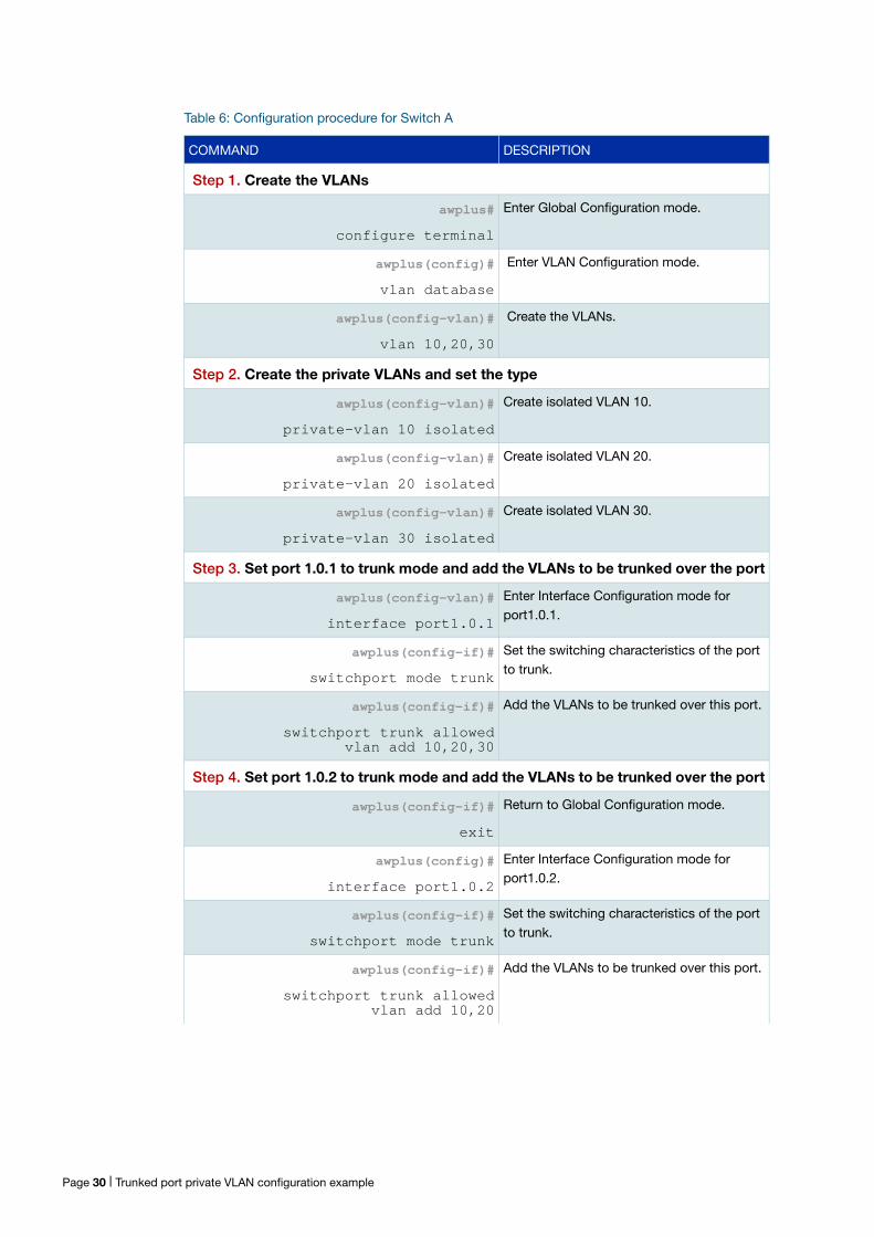
Table 6: Configuration procedure for Switch A
COMMAND DESCRIPTION
Step 1. Create the VLANs
awplus#
configure terminal
Enter Global Configuration mode.
awplus(config)#
vlan database
Enter VLAN Configuration mode.
awplus(config-vlan)#
vlan 10,20,30
Create the VLANs.
Step 2. Create the private VLANs and set the type
awplus(config-vlan)#
private-vlan 10 isolated
Create isolated VLAN 10.
awplus(config-vlan)#
private-vlan 20 isolated
Create isolated VLAN 20.
awplus(config-vlan)#
private-vlan 30 isolated
Create isolated VLAN 30.
Step 3. Set port 1.0.1 to trunk mode and add the VLANs to be trunked over the port
awplus(config-vlan)#
interface port1.0.1
Enter Interface Configuration mode for port1.0.1.
awplus(config-if)#
switchport mode trunk
Set the switching characteristics of the port to trunk.
awplus(config-if)#
switchport trunk allowed vlan add 10,20,30
Add the VLANs to be trunked over this port.
Step 4. Set port 1.0.2 to trunk mode and add the VLANs to be trunked over the port
awplus(config-if)#
exit
Return to Global Configuration mode.
awplus(config)#
interface port1.0.2
Enter Interface Configuration mode for port1.0.2.
awplus(config-if)#
switchport mode trunk
Set the switching characteristics of the port to trunk.
awplus(config-if)#
switchport trunk allowed vlan add 10,20
Add the VLANs to be trunked over this port.
Page 30 | Trunked port private VLAN configuration example
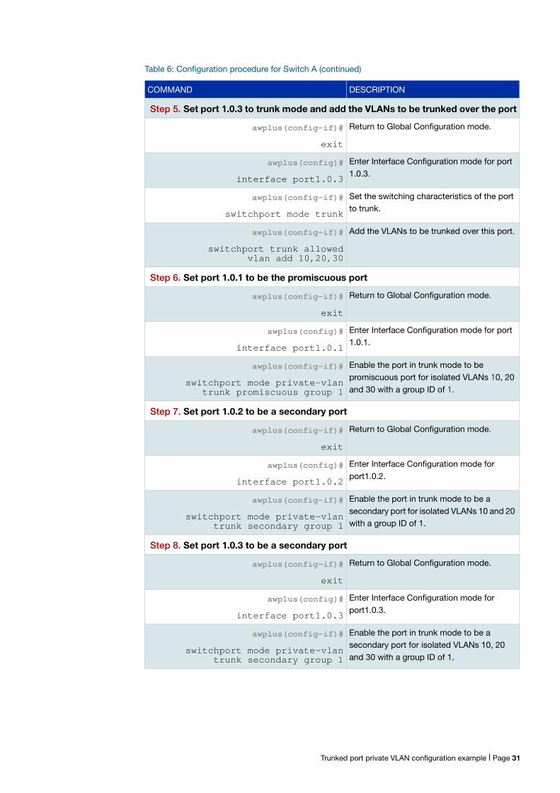
Step 5. Set port 1.0.3 to trunk mode and add the VLANs to be trunked over the port
awplus(config-if)#
exit
Return to Global Configuration mode.
awplus(config)#
interface port1.0.3
Enter Interface Configuration mode for port 1.0.3.
awplus(config-if)#
switchport mode trunk
Set the switching characteristics of the port to trunk.
awplus(config-if)#
switchport trunk allowed vlan add 10,20,30
Add the VLANs to be trunked over this port.
Step 6. Set port 1.0.1 to be the promiscuous port
awplus(config-if)#
exit
Return to Global Configuration mode.
awplus(config)#
interface port1.0.1
Enter Interface Configuration mode for port 1.0.1.
awplus(config-if)#
switchport mode private-vlan trunk promiscuous group 1
Enable the port in trunk mode to be promiscuous port for isolated VLANs 10, 20 and 30 with a group ID of 1.
Step 7. Set port 1.0.2 to be a secondary port
awplus(config-if)#
exit
Return to Global Configuration mode.
awplus(config)#
interface port1.0.2
Enter Interface Configuration mode for port1.0.2.
awplus(config-if)#
switchport mode private-vlan trunk secondary group 1
Enable the port in trunk mode to be a secondary port for isolated VLANs 10 and 20 with a group ID of 1.
Step 8. Set port 1.0.3 to be a secondary port
awplus(config-if)#
exit
Return to Global Configuration mode.
awplus(config)#
interface port1.0.3
Enter Interface Configuration mode for port1.0.3.
awplus(config-if)#
switchport mode private-vlan trunk secondary group 1
Enable the port in trunk mode to be a secondary port for isolated VLANs 10, 20 and 30 with a group ID of 1.
Table 6: Configuration procedure for Switch A (continued)
COMMAND DESCRIPTION
Trunked port private VLAN configuration example | Page 31
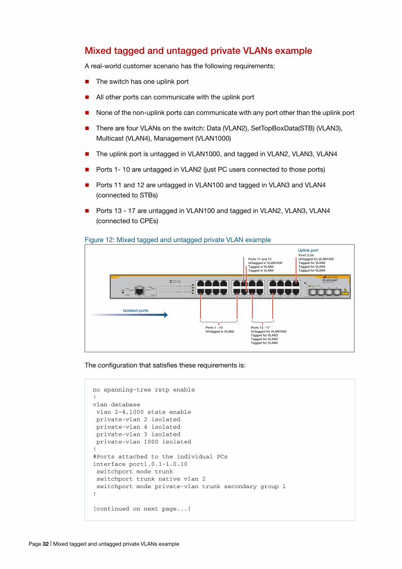
Mixed tagged and untagged private VLANs example
A real-world customer scenario has the following requirements:
The switch has one uplink port
All other ports can communicate with the uplink port
None of the non-uplink ports can communicate with any port other than the uplink port
There are four VLANs on the switch: Data (VLAN2), SetTopBoxData(STB) (VLAN3),
Multicast (VLAN4), Management (VLAN1000)
The uplink port is untagged in VLAN1000, and tagged in VLAN2, VLAN3, VLAN4
Ports 1- 10 are untagged in VLAN2 (just PC users connected to those ports)
Ports 11 and 12 are untagged in VLAN100 and tagged in VLAN3 and VLAN4 (connected to STBs)
Ports 13 - 17 are untagged in VLAN100 and tagged in VLAN2, VLAN3, VLAN4
(connected to CPEs)
no spanning-tree rstp enable!vlan database vlan 2-4,1000 state enable private-vlan 2 isolated private-vlan 4 isolated private-vlan 3 isolated private-vlan 1000 isolated!#Ports attached to the individual PCsinterface port1.0.1-1.0.10 switchport mode trunk switchport trunk native vlan 2 switchport mode private-vlan trunk secondary group 1!
[continued on next page...]
Figure 12: Mixed tagged and untagged private VLAN example
The configuration that satisfies these requirements is:
1 3 5 7
2 4 6 8
9 11 13 15R
10 12 14 16R
17 19 21 23R
18 20 22 24R
AT-x210-24GTGigabit Ethernet Switch
15 16 23 24
L/A
2 4 6 8 10 12 14 16R 18 20 22 24R
MODE
L/A
MODE
CONSOLE
RS-232
FAULTSTANDBYRESET
POWER
SELECT
1 3 5 7 9 11 13 15R 17 19 21 23R15
16
23
24
SPEED
DUPLEX
MODE
MODE SPEED / DUPLEX
L/A LINK / ACT
L/A LINK / ACT
SFP
CLASS 1LASER PRODUCT
Port1.0.24Untagged for VLAN1000Tagged for VLAN2Tagged for VLAN3Tagged for VLAN4
Ports 13 - 17Untagged for VLAN1000Tagged for VLAN2Tagged for VLAN3Tagged for VLAN4
Ports 11 and 12Untagged in VLAN1000Tagged in VLAN3Tagged in VLAN4
Ports 1 - 10Untagged in VLAN2
Isolated ports
Uplink port
Page 32 | Mixed tagged and untagged private VLANs example
#Ports attached to the STBs - management on vlan1000interface port1.0.11-1.0.12 switchport mode trunk switchport trunk allowed vlan add 3,4 switchport trunk native vlan 1000 switchport mode private-vlan trunk secondary group 1!#Ports attachd to the CPEsinterface port1.0.13-1.0.17 switchport mode trunk switchport trunk allowed vlan add 2-4 switchport trunk native vlan 1000 switchport mode private-vlan trunk secondary group 1!#Uplink portinterface port1.0.24 switchport mode trunk switchport trunk allowed vlan add 2-4 switchport trunk native vlan 1000 switchport mode private-vlan trunk promiscuous group 1
Combining Private VLANs with Other Features - LimitationsThere are several limitations when combining the private VLANs feature with other
features:
Using private VLANs with EPSR
You cannot have Ethernet Protected Switching Ring (EPSR) configured on the switch at
the same time as private VLANs. Private VLANs allow only one promiscuous port,
whereas EPSR topologies require two interfaces to be part of the EPSR loop.
Using private VLANs with ARP
Devices that are connected to an Isolated VLAN’s Host Port cannot use Address
Resolution Protocol (ARP) to find the switch's IP address. All packets that the Host Port
receives are sent directly out via the promiscuous port, without following any of the
normal switching operations. This means that ARP requests received on a Host Port are
sent to the promiscuous port instead of the CPU port, and therefore the CPU does not
process them.
For this reason, you cannot ping a switch through a Host Port or use Simple Network
Management Protocol (SNMP) or Telnet to manage the switch through a host port, unless
static ARPs are added to the devices at both ends of the host port's link.
Using private VLANs with EPSR | Page 33
This functionality protects your network. Devices connected to Isolated VLANs’ host ports
are typically not trusted, and this prevents them from having management access to the
switch.
This functionality also means that, without static ARPs, you can't process Layer 3
switching through a host port, since ARPs are required to resolve the nexthops. Receiving
packets on a host port and Layer 3 switching them to a non-private port on another VLAN
is a solution, however, traffic coming the other way won’t process, as ARPs cannot be
dynamically learned on the host port.
Using private VLANs with LLDP
Link Layer Discovery Protocol (LLDP) does not work on trunked interfaces. Any private
VLAN solution trunked interfaces cannot also have LLDP configured.
Using private VLANs with GVRP
Private VLAN trunk ports are not supported for GVRP. Private VLAN trunk ports and GVRP
are mutually exclusive.
Using private VLANs with link aggregation
Once you have created a static channel or LACP, configure this aggregate interface as the
promiscuous port, or even as a secondary host interface. Note that the promiscuous/
secondary port status cannot be applied to the individual ports within the aggregation, it
can only be applied to the aggregation itself.
Using private VLANs with management utility servers
SNMP, sFlow, DHCP, SYSLOG and other management servers should not be connected
to isolated ports.
Page 34 | Using private VLANs with LLDP
Protocol-Based VLANSUp until now, we have been thinking just of port-based VLANs. However, there are other
ways of defining VLAN membership. In this section, we will consider another type of VLAN
- namely the Protocol-Based VLAN.
With this VLAN classification method, different protocol types are assigned to different
VLANs. For example, IP defines one VLAN, IPX defines another VLAN, Netbeui yet
another VLAN, etc.
It is possible that a question will come to your mind at this point, like:
“Isn't a VLAN a set of workstations? How does a protocol specify a workstation? Surely a
given workstation can send out packets using different protocols (often at the same time),
depending on which applications it is running?”
At this point, you may be starting to see that the description of a VLAN as a set of
workstations is a bit of a simplification. So, let us look a bit deeper here and get to a better
understanding of what VLAN membership means.
In fact, a given workstation can belong to multiple VLANs. It could belong to one protocol-
based VLAN when sending IP packets, another protocol-based VLAN when sending IPX
packets, and yet another different port-based VLAN when sending some other protocol.
So, certainly, when analyzing the VLAN setup on a network, it is a mistake to ask “what
VLAN does this workstation belong to?” The more meaningful question to ask is “if a
packet of such-and-such a protocol arrived at port x of the switch, which VLAN would that
packet be associated with?”
It is important to really understand the change of mind-set that has just been introduced
here. When initially learning about VLANs, it is usual to think of VLANs as sets of
workstations. And, in practice, this is often all that a network administrator wants to
achieve.
However, once the VLAN configuration on a switch becomes complex, with multiple
VLANs of different types all configured on the same port, it is no longer possible to really
think about the VLAN from the workstation point of view. It becomes necessary to think of
it from the packet point of view.
Therefore, it really is vital to think of packets being associated to VLANs when trying to
understand VLAN configurations. Any other approach just ends in confusion. The main
point is that, when using protocol-based VLANs, it is data streams that are divided into
VLANs, not necessarily whole workstations.
Using private VLANs with management utility servers | Page 35
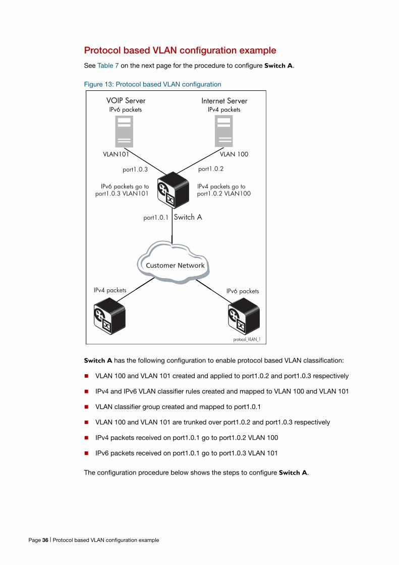
Protocol based VLAN configuration example
See Table 7 on the next page for the procedure to configure Switch A.
Figure 13: Protocol based VLAN configuration
Switch A has the following configuration to enable protocol based VLAN classification:
VLAN 100 and VLAN 101 created and applied to port1.0.2 and port1.0.3 respectively
IPv4 and IPv6 VLAN classifier rules created and mapped to VLAN 100 and VLAN 101
VLAN classifier group created and mapped to port1.0.1
VLAN 100 and VLAN 101 are trunked over port1.0.2 and port1.0.3 respectively
IPv4 packets received on port1.0.1 go to port1.0.2 VLAN 100
IPv6 packets received on port1.0.1 go to port1.0.3 VLAN 101
The configuration procedure below shows the steps to configure Switch A.
protocol_VLAN_1
IPv6 packetsIPv4 packets
VOIP Server
VLAN 100VLAN101
Switch Aport1.0.1
Internet Server
port1.0.2port1.0.3
Customer Network
IPv4 packets go toport1.0.2 VLAN100
IPv6 packets go toport1.0.3 VLAN101
IPv6 packets IPv4 packets
Page 36 | Protocol based VLAN configuration example
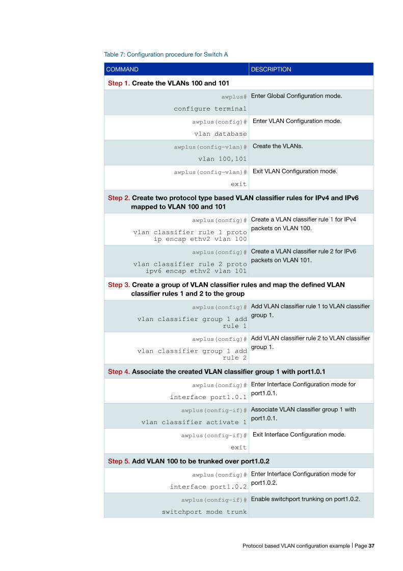
Table 7: Configuration procedure for Switch A
COMMAND DESCRIPTION
Step 1. Create the VLANs 100 and 101
awplus#
configure terminal
Enter Global Configuration mode.
awplus(config)#
vlan database
Enter VLAN Configuration mode.
awplus(config-vlan)#
vlan 100,101
Create the VLANs.
awplus(config-vlan)#
exit
Exit VLAN Configuration mode.
Step 2. Create two protocol type based VLAN classifier rules for IPv4 and IPv6 mapped to VLAN 100 and 101
awplus(config)#
vlan classifier rule 1 proto ip encap ethv2 vlan 100
Create a VLAN classifier rule 1 for IPv4 packets on VLAN 100.
awplus(config)#
vlan classifier rule 2 proto ipv6 encap ethv2 vlan 101
Create a VLAN classifier rule 2 for IPv6 packets on VLAN 101.
Step 3. Create a group of VLAN classifier rules and map the defined VLAN classifier rules 1 and 2 to the group
awplus(config)#
vlan classifier group 1 add rule 1
Add VLAN classifier rule 1 to VLAN classifier group 1.
awplus(config)#
vlan classifier group 1 add rule 2
Add VLAN classifier rule 2 to VLAN classifier group 1.
Step 4. Associate the created VLAN classifier group 1 with port1.0.1
awplus(config)#
interface port1.0.1
Enter Interface Configuration mode for port1.0.1.
awplus(config-if)#
vlan classifier activate 1
Associate VLAN classifier group 1 with port1.0.1.
awplus(config-if)#
exit
Exit Interface Configuration mode.
Step 5. Add VLAN 100 to be trunked over port1.0.2
awplus(config)#
interface port1.0.2
Enter Interface Configuration mode for port1.0.2.
awplus(config-if)#
switchport mode trunk
Enable switchport trunking on port1.0.2.
Protocol based VLAN configuration example | Page 37
VLAN StatisticsThis feature provides a series of data counters each able to count both the number of
received frames or the number of received bytes (octets) belonging to a particular VLAN.
Data frames are counted as they enter the switch ports. By allocating VLANs to each
customer, a service provider could use the VLAN counter output to provide the basis for a
traffic based billing component.
Commands
Use these commands to create a VLAN packet counter instance named vlan2-data, and
apply this to count incoming vlan2 tagged frames on ports 1.0.4 and 1.0.5:
awplus(config)# interface port1.0.4,port1.0.5
awplus (config-if)# vlan 2 statistics name vlan2-data
To view the counters, use the following command:
awplus# show vlan statistics [name <instance_name>]
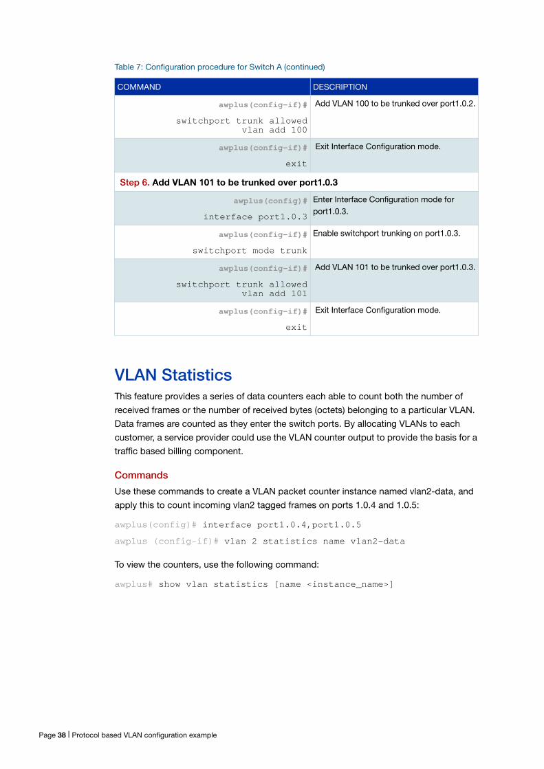
awplus(config-if)#
switchport trunk allowed vlan add 100
Add VLAN 100 to be trunked over port1.0.2.
awplus(config-if)#
exit
Exit Interface Configuration mode.
Step 6. Add VLAN 101 to be trunked over port1.0.3
awplus(config)#
interface port1.0.3
Enter Interface Configuration mode for port1.0.3.
awplus(config-if)#
switchport mode trunk
Enable switchport trunking on port1.0.3.
awplus(config-if)#
switchport trunk allowed vlan add 101
Add VLAN 101 to be trunked over port1.0.3.
awplus(config-if)#
exit
Exit Interface Configuration mode.
Table 7: Configuration procedure for Switch A (continued)
COMMAND DESCRIPTION
Page 38 | Protocol based VLAN configuration example
Counter operation
In this section we detail two scenarios: in the first scenario the switch is being used at the
edge of the network; in the second scenario it is directly connected to an edge switch. In
each situation, separate counters are maintained for incoming traffic that is associated
with a particular VLAN across a range of ports. This enables both incoming and outgoing
traffic volumes to be measured.
A port may not be assigned to multiple counter instances so as to count frames (or bytes)
within the same VLAN. The byte count includes frame headers, therefore the byte counter
for a VLAN tagged frame will be 4 bytes longer than for an untagged frame.
Where a VLAN packet counter instance encompasses ports on a stacked member and
the member is removed from the stack, these ports will automatically be removed from
the counter instance. If this process removes all ports within a counter instance, then the
instance will be deleted.
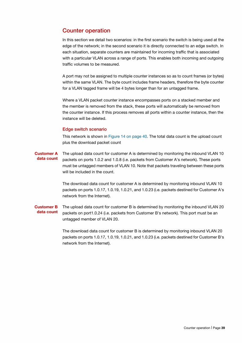
Edge switch scenario
This network is shown in Figure 14 on page 40. The total data count is the upload count
plus the download packet count
Customer A data count
The upload data count for customer A is determined by monitoring the inbound VLAN 10
packets on ports 1.0.2 and 1.0.8 (i.e. packets from Customer A's network). These ports
must be untagged members of VLAN 10. Note that packets traveling between these ports
will be included in the count.
The download data count for customer A is determined by monitoring inbound VLAN 10
packets on ports 1.0.17, 1.0.19, 1.0.21, and 1.0.23 (i.e. packets destined for Customer A's
network from the Internet).
Customer B data count
The upload data count for customer B is determined by monitoring the inbound VLAN 20
packets on port1.0.24 (i.e. packets from Customer B's network). This port must be an
untagged member of VLAN 20.
The download data count for customer B is determined by monitoring inbound VLAN 20
packets on ports 1.0.17, 1.0.19, 1.0.21, and 1.0.23 (i.e. packets destined for Customer B's
network from the Internet).
Counter operation | Page 39
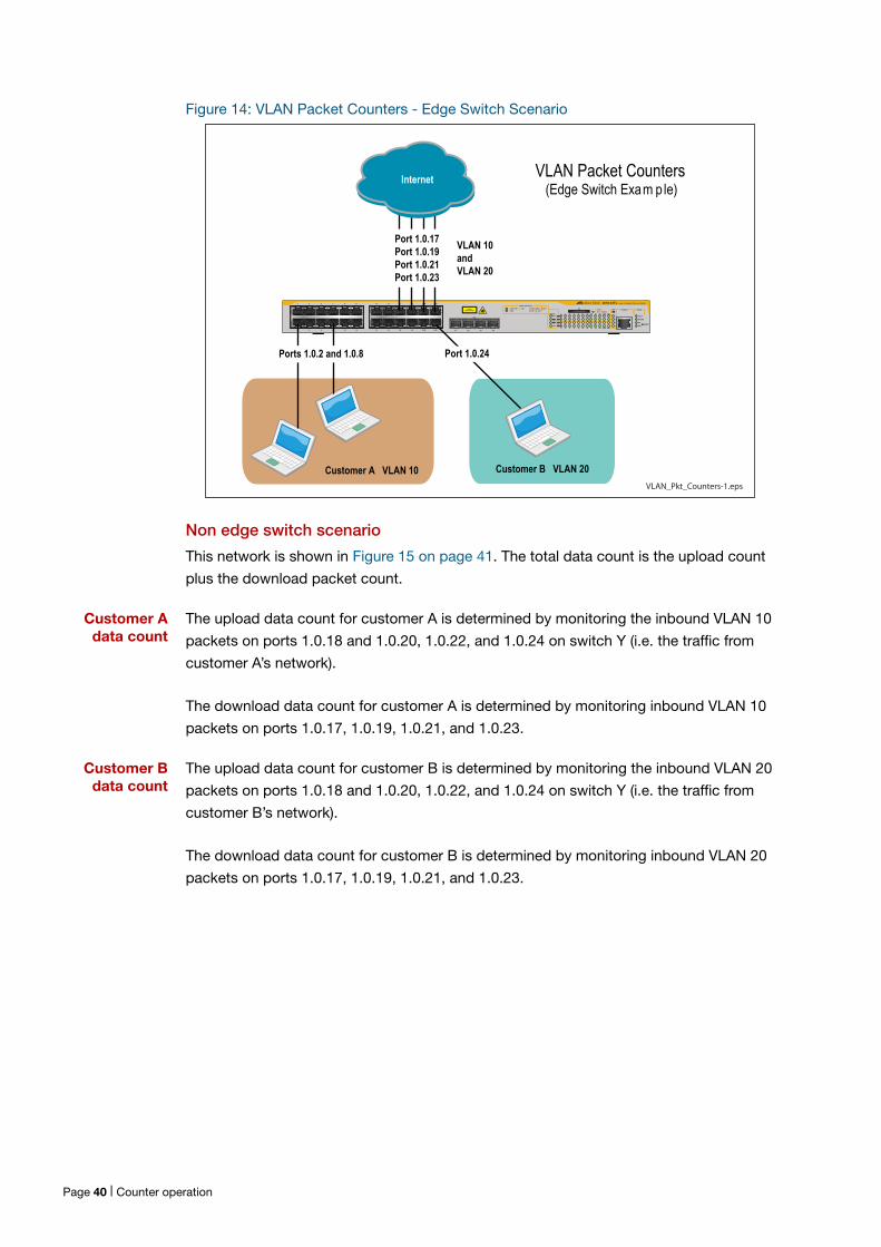
Figure 14: VLAN Packet Counters - Edge Switch Scenario
Non edge switch scenario
This network is shown in Figure 15 on page 41. The total data count is the upload count
plus the download packet count.
Customer A data count
The upload data count for customer A is determined by monitoring the inbound VLAN 10
packets on ports 1.0.18 and 1.0.20, 1.0.22, and 1.0.24 on switch Y (i.e. the traffic from
customer A’s network).
The download data count for customer A is determined by monitoring inbound VLAN 10
packets on ports 1.0.17, 1.0.19, 1.0.21, and 1.0.23.
Customer B data count
The upload data count for customer B is determined by monitoring the inbound VLAN 20
packets on ports 1.0.18 and 1.0.20, 1.0.22, and 1.0.24 on switch Y (i.e. the traffic from
customer B’s network).
The download data count for customer B is determined by monitoring inbound VLAN 20
packets on ports 1.0.17, 1.0.19, 1.0.21, and 1.0.23.
VLAN_Pkt_Counters-1.eps
1 3 5 7 9 11 13 15 17 19 21R 23R
2 4 6 8 10 12 14 16 18 20 22R 24R
x610-24Ts Layer 3 Gigabit Ethernet Switch
CLASS 1LASER PRODUCT D/C
L/A 1000 LINK / ACTHDX / COLFDX10/100 LINK / ACT
PORT ACTIVITY
L/A
D/C
D/C
L/AL/A
STACK
PRES
MSTR
L/A1
2
SFP
21 22 23 24
1 3 5 7 9 11 13 15 17 19 21R 23R
2 4 6 8 10 12 14 16 18 20 22R 24R
FAULT
RPS
MASTER
PWR
STATUS
21
22
23
24
SFPL/ABUSY
READY
FAULT
SD
RESET
CONSOLE
VLAN Packet Counters (Edge Switch Exam ple)
Ports 1.0.2 and 1.0.8 Port 1.0.24
Customer B VLAN 20Customer A VLAN 10
Port 1.0.17Port 1.0.19Port 1.0.21Port 1.0.23
VLAN 10andVLAN 20
Internet
Page 40 | Counter operation
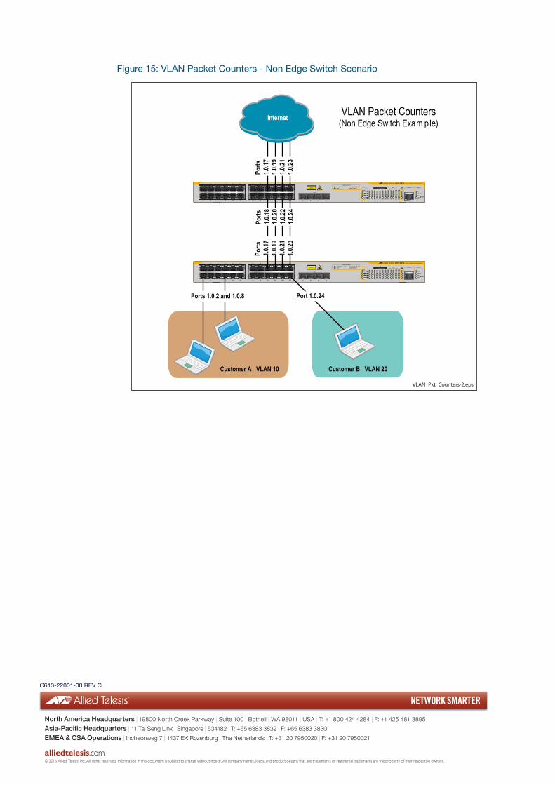
Figure 15: VLAN Packet Counters - Non Edge Switch Scenario
VLAN_Pkt_Counters-2.eps
1 3 5 7 9 11 13 15 17 19 21R 23R
2 4 6 8 10 12 14 16 18 20 22R 24R
x610-24Ts Layer 3 Gigabit Ethernet Switch
CLASS 1LASER PRODUCT D/C
L/A 1000 LINK / ACTHDX / COLFDX10/100 LINK / ACT
PORT ACTIVITY
L/A
D/C
D/C
L/AL/A
STACK
PRES
MSTR
L/A1
2
SFP
21 22 23 24
1 3 5 7 9 11 13 15 17 19 21R 23R
2 4 6 8 10 12 14 16 18 20 22R 24R
FAULT
RPS
MASTER
PWR
STATUS
21
22
23
24
SFPL/ABUSY
READY
FAULT
SD
RESET
CONSOLE
1 3 5 7 9 11 13 15 17 19 21R 23R
2 4 6 8 10 12 14 16 18 20 22R 24R
x610-24Ts Layer 3 Gigabit Ethernet Switch
CLASS 1LASER PRODUCT D/C
L/A 1000 LINK / ACTHDX / COLFDX10/100 LINK / ACT
PORT ACTIVITY
L/A
D/C
D/C
L/AL/A
STACK
PRES
MSTR
L/A1
2
SFP
21 22 23 24
1 3 5 7 9 11 13 15 17 19 21R 23R
2 4 6 8 10 12 14 16 18 20 22R 24R
FAULT
RPS
MASTER
PWR
STATUS
21
22
23
24
SFPL/ABUSY
READY
FAULT
SD
RESET
CONSOLE
Ports
1.0.17
1.0.19
1.0.21
1.0.23
Ports
1.0.18
1.0.20
1.0.22
1.0.24
Ports
1.0.17
1.0.19
1.0.21
1.0.23
VLAN Packet Counters(Non Edge Switch Exam ple)
Ports 1.0.2 and 1.0.8 Port 1.0.24
Customer B VLAN 20Customer A VLAN 10
Internet
C613-22001-00 REV C
NETWORK SMARTER
alliedtelesis.com
North America Headquarters | 19800 North Creek Parkway | Suite 100 | Bothell | WA 98011 | USA | T: +1 800 424 4284 | F: +1 425 481 3895
Asia-Pacific Headquarters | 11 Tai Seng Link | Singapore | 534182 | T: +65 6383 3832 | F: +65 6383 3830
EMEA & CSA Operations | Incheonweg 7 | 1437 EK Rozenburg | The Netherlands | T: +31 20 7950020 | F: +31 20 7950021
© 2016 Allied Telesis, Inc. All rights reserved. Information in this document is subject to change without notice. All company names, logos, and product designs that are trademarks or registered trademarks are the property of their respective owners.
Recommended