IOP Conference Series Materials Science and Engineering
PAPER bull OPEN ACCESS
Modeling and Stress Analysis of Pump PipingTo cite this article N Prabhu Kishore and S Prabhu 2018 IOP Conf Ser Mater Sci Eng 455012100
View the article online for updates and enhancements
Recent citationsPipe Stress Analysis of Pump System inProcess PlantAkhilesh Kumar Jha et al
-
The analysis of a piping system forimprovement of a system in a process unitRajath N Rao et al
-
This content was downloaded from IP address 6521228167 on 06102021 at 2144
Content from this work may be used under the terms of the Creative Commons Attribution 30 licence Any further distributionof this work must maintain attribution to the author(s) and the title of the work journal citation and DOI
Published under licence by IOP Publishing Ltd
ICAAMM
IOP Conf Series Materials Science and Engineering455 (2018) 012100
IOP Publishing
doi1010881757-899X4551012100
1
MODELING AND STRESS ANALYSIS OF PUMP PIPING
NPrabhu Kishore 1 SPrabhu2
1 Associate professor Department of Mechanical Engineering MLR Institute of
Technology Hyderabad
2 MTech Scholar MLR Institute of Technology Dundigal Hyderabad
Email prabhupatil84gmailcom prabhunutakkigmailcom
Abstract Every process piping industry uses several pumps in each process unit Sometimes the analysis is very critical This article e xpla ins about elaborate the method followed for stress analysis of a pump piping system The stress system consists of typical discharge and suction lines of two pumps Fluid from the tank is pumped to another As per PampID only one pump will operate at a time other pump will be a stand by pump This article exp lains about the stress analysis methodology in three parts - a) Modeling of Pump b) Preparation of analysis Load cases and c) analyzing the output results Externa l loads imposed by piping on rotating equipment nozzle should be less than allowed loads If e xcessive loads are imposed misalignment may result that affects mechanical operation and could cause objectionable vibration A close alignment between rotating and stationary parts must be maintained The provision for e xpansion of the casing and maintaining close clearances requires that the forces and moments due to the piping are limited The API 610 standard gives equation to calculate allowable forces and moments in the case of pumps for general refinery service The criteria apply for pumps with 4 Inches discharge nozzles or smaller (suction nozzle may be larger) and situations where the pump is constructed of steel or alloy steel The modulus of elasticity of the piping material at operating temperature (known as ho t modulus) can be used to calculate actual loads Using hot modulus will result in lower loads because the piping is more flexible at higher temperature This paper is designed for studying a wide range of abilities and backgrounds this will cover the fundamental principles concepts used in pipe stress analysis
1 INTRODUCTION
Piping system is the artery of fluid transportation to the pant For safe operation design of piping system plays major role in safeguard of entire assets which require detailed engineering and analysis To perform detailed engineering the plant requires the plan to develop the routing feasibility and that routing shall be stress freed as the piping fluid with pressure and temperature This piping routing shall be carried out with the help of scheme and Piping amp Instrumentation Diagrams (PampID) The purpose of this paper is to design and finalizing the piping routing of Pump suction and discharge The software CAESER-II is used to check the piping systemrsquos flexibility to find within the stress limits of acceptable codes and standards
ICAAMM
IOP Conf Series Materials Science and Engineering455 (2018) 012100
IOP Publishing
doi1010881757-899X4551012100
2
Piping stress analysis is an important study where the material behavior is analyzed with pressure thermal effects of travelling fluid and when where reaction of piping supports and nozzle terminals are shall be evaluated to the designed limits
2 Execution of piping stress analysis
a Preparation of critical piping line list In a process complex the piping networks are segregated into their working process conditions The criticality of the piping system is studied by its operation of fluid pressure temperature velocity density pipe size amp schedule material class etc with all these parameters systemnetwork wise list prepared and issued as input for the system analysis
b Documents Required
For analysis to execute in Caesar-II software following inputs are required PampID Critical line list Piping Isometrics with support feasibilities Equipmentvendor drawings (Eg For pump system Pump vendor drawings amp applicable codes like API-610 Tank General Arrangement drawing amp applicable code API-650) project piping support standard ASME-313 code requirements etc
c Pipe Stress Analysis Software
In oil and gas power industries there are approved softwarersquos to assess piping flexibilities like CAESAR-II (Computer Aided Engineering and Stress Analysis Reviewer) Auto Pipe Nozzle proamp FEA (Finite Element Analysis) CAEPIPE etc
For this study report we used CAESAR-II software which widely used to check the piping flexibility
Inputmodel the piping network in Caesar-II put appropriate support as per requirement analyze the system where required use the piping loops and change in direction to absorb the thermal expansion review the displacements piping support loads check the stress limits as applicable and report the assessment
Figure1 Operational Graph
ICAAMM
IOP Conf Series Materials Science and Engineering455 (2018) 012100
IOP Publishing
doi1010881757-899X4551012100
3
The following summary to design piping flexibility Study to route the piping with support feasibility and access for operation as per PampID
Provide the adequate piping support and with acceptable span to prevent excessive sagging
Provide sufficient flexibility for piping to absorb thermal expansion or contraction to safeguard and to prevent excessive stress at piping or at equipment nozzles
Once the piping qualified in all aspects of design isometrics are issued to construction
a) To keep the stresses in the pipes and fittings within the code allowable levels b) To keep the nozzle loadings on the attached equipment within allowable limits of applicable specifications or recognized standards (NEMA SM23 API 610 API 661 etc) c) To minimize vibration of the reciprocating compressor associated piping d) To calculate the design loads for sizing of in-line restraints such as U-bolt Shoe Clamp Trunnion Guide Stop etc sizing of support frames and selection of spring hangers e) To determine the piping displacements for interference check and prevent excessive sag in piping spans f) To check the leakage at the flange joints g) To prevent unintentional disengagement of piping from its supports h) To help optimize the piping design
3 Codes and Standards Design and analysis of the piping shall be in accordance with following codes
ICAAMM
IOP Conf Series Materials Science and Engineering455 (2018) 012100
IOP Publishing
doi1010881757-899X4551012100
4
SSTTRREESSSS AANNAALLYYSSIISS FFLLOOWW CHART
Generating Reports
Analysis(StressLoadsDisplacement)
RunChecking the Errors amp Warnings
Inputs in the Software
Pipe Stress Analysis(Software)
Documents(Isometrics)
Preparation of Critical Line List
4 PROCEDURE OF ANALYSIS
Figure2 Flow chart of stress analysis
ICAAMM
IOP Conf Series Materials Science and Engineering455 (2018) 012100
IOP Publishing
doi1010881757-899X4551012100
5
Table1 Pump process data sheet
Table2Process Critical Line List
FLUI D FLUI D TEST NDT
SRNO REV Pamp id N O SEQ SIZ E FLUI D PIPING P amp id N O LIN EN O PRESS URE TEMP PRESS URE TEMP STR ESS STR ESS ANA LYSIS DEN SI TY PHASE PRESSMUREDE IU M PWHT RT MT OR L T VISUA L PAINTING AREA REMARKS
NO NO NPS CODE CLASS BARG DEG C
60 1 0007 211 6 HC A2 CSN ZP- 50- PR- 25- 0007 211 -6- HC- A2 CSN ATM 30 0 1 - 29 8 Y SYS- 012 74 LIQ UID 3 H N 10 10 () 10 0 CS- 1 BOP
65 1 0008 212 4 HC A2 CSN ZP- 50- PR- 25- 0008 211 -4- HC- A2 CSN 3 30 0 1 - 29 8 Y SYS- 012 74 LIQ UID 15 H N 10 10 () 10 0 CS- 1 BOP
66 1 0008 213 5 HC A2 CSN ZP- 50- PR- 25- 0008 211 -2- HC- A2 CSN 3 30 0 1 - 29 8 Y SYS- 012 74 LIQ UID 3 H N 10 10 () 10 0 CS- 1 BOP
67 1 0008 214 4 HC A2 CSN ZP- 50- PR- 25- 0008 211 -4- HC- A2 CSN ATM 30 0 1 - 29 8 Y SYS- 012 74 LIQ UID 15 H N 10 10 () 10 0 CS- 1 BOP
68 1 0008 229 4 HC A2 CSN ZP- 50- PR- 25- 0008 211 -4- HC- A2 CSN 3 30 0 1 - 29 8 N SYS- 012 74 LIQ UID 15 H N 10 10 () 10 0 CS- 1 BOP
70 1 0008 223 6 HC A2 CSN ZP- 50- PR- 25- 0008 211 -6- HC- A2 CSN ATM 30 0 1 - 29 8 Y SYS- 012 74 LIQ UID 3 H N 10 10 () 10 0 CS- 1 BOP
71 1 0008 224 4 HC A2 CSN ZP- 50- PR- 25- 0008 211 -4- HC- A2 CSN 3 30 0 1 - 29 8 Y SYS- 012 74 LIQ UID 15 H N 10 10 () 10 0 CS- 1 BOP
ICAAMM
IOP Conf Series Materials Science and Engineering455 (2018) 012100
IOP Publishing
doi1010881757-899X4551012100
6
FIGURE 3 Stress Isometric with Nodes
FIGURE 4 Caesar-II Model
5 LISTING OF STATIC LOAD CASES FOR PUMP PIPING (SUCTION AND DISCHARGE) ANALYSIS
ICAAMM
IOP Conf Series Materials Science and Engineering455 (2018) 012100
IOP Publishing
doi1010881757-899X4551012100
7
6 RESULTS
ICAAMM
IOP Conf Series Materials Science and Engineering455 (2018) 012100
IOP Publishing
doi1010881757-899X4551012100
8
TCStressSummary Multiple f CLOAD CASE DEFINITION KEY CASE 1 (HYD) WV+HP CASE 8 (SUS) W+Pl CASE 25 (OCC) L25=Ll 7+L8 CASE 26 (OCC) L26=Ll 8+L8 CASE 27 (OCC) L27=L19+L8 CASE 28 (OCC) L28=L20+L8 CASE 29 (OCC) L29=L21+L8 CASE 30 (OCC) L30=L22+L8 CASE 31 (OCC) L3l =L23+L8 CASE 32 (OCC) L32=L24+L8 CASE 33 (EXP) L33=L2-L8 CASE 34 (EXP) L34=L3-L8 CASE 35 (EXP) L35=L4-L8 CASE 36 (EXP) L36=L5-L8 CASE 37 (EXP) L37=L33+L35
Piping Code B3l 3 = B3l 3 -2008 December 31 2008
CODE STRESS CHECK PASSED LOADCASE 1 (HYD) WW+HP Highes t Stresses (NJ sqmm ) LOADCASE 1 (HYD) WW+HP Code Stress Ratio () 183 Node 5060 Code Stress 441 Allowable 2413 Axial Stress 441 Node 5060 Bending Stress 153 Node 15120 Torsion Stress 63 Node 15180 Hoop Stress 883 Node 5047 3D Max Intensity 887 Node 5047
CODE STRESS CHECK PASSED LOADCASE 8 (SUS) W+Pl Highes t Stresses (NJ sqmm ) LOADCASE 8 (SUS) W+Pl Code Stress Ratio () 253 Node 15120 Code Stress 349 Allowable 1379 Axial Stress 57 Node 12090 Bending Stress 340 Node 15120 Torsion Stress 133 Node 15180 Hoop Stress 117 Node 12085 3D Max Intensity 433 Node 15120 CODE STRESS CHECK PASSED LOADCASE 25 (OCC) L25=Ll 7+L8 Highes t Stresses (NJ sqmm ) LOADCASE 25 (OCC) L25=Ll 7+L8 Code Stress Ratio () 209 Node 15120 Code Stress 383 Allowable 1834 Axial Stress 58 Node 12090 Bending Stress 371 Node 15120 Torsion Stress 128 Node 15180 Hoop Stress 117 Node 12085 3D Max Intensity 467 Node 15120
ICAAMM
IOP Conf Series Materials Science and Engineering455 (2018) 012100
IOP Publishing
doi1010881757-899X4551012100
9
CODE STRESS CHECK PASSED LOADCASE 26 (OCC) L26=L18+L8 Highes t Stresses (NJ sqmm ) LOADCASE 26 (OCC) L26=L18+L8 Code Stress Ratio () 212 Node 15120 Code Stress 388 Allowable 1834 Axial Stress 57 Node 12090 Bending Stress 372 Node 15120 Torsion Stress 138 Node 15180 Hoop Stress 117 Node 12085 3D Max Intensity 474 Node 15120
CODE STRESS CHECK PASSED LOADCASE 27 (OCC) L27=L19+L8 Highes t Stresses (NJ sqmm ) LOADCASE 27 (OCC) L27=L19+L8 Code Stress Ratio () 333 Node 15120 Code Stress 611 Allowable 1834 Axial Stress 58 Node 12090 Bending Stress 586 Node 15120 Torsion Stress 165 Node 15120 Hoop Stress 117 Node 12085 3D Max Intensity 733 Node 15180
CODE STRESS CHECK PASSED LOADCASE 28 (OCC) L28=L20+L8 Highes t Stresses (NJ sqmm ) LOADCASE 28 (OCC) L28=L20+L8 Code Stress Ratio () 299 Node 15120 Code Stress 549 Allowable 1834 Axial Stress 58 Node 12090 Bending Stress 538 Node 15120 Torsion Stress 147 Node 15180 Hoop Stress 117 Node 12085 3D Max Intensity 643 Node 15120
CODE STRESS CHECK PASSED LOADCASE 29 (OCC) L29=L21+L8 Highes t Stresses (NJ sqmm ) LOADCASE 29 (OCC) L29=L21+L8 Code Stress Ratio () 491 Node 15120 Code Stress 900 Allowable 1834 Axial Stress 58 Node 12085 Bending Stress 842 Node 12040 Torsion Stress 192 Node 11260 Hoop Stress 117 Node 12085 3D Max Intensity 987 Node 15120
ICAAMM
IOP Conf Series Materials Science and Engineering455 (2018) 012100
IOP Publishing
doi1010881757-899X4551012100
10
CODE STRESS CHECK PASSED LOADCASE 30 (OCC) L30=L22+L8 Highes t Stresses (NJ sqmm ) LOADCASE 30 (OCC) L30=L22+L8 Code Stress Ratio () 483 Node 15120 Code Stress 886 Allowable 1834 Axial Stress 59 Node 12040 Bending Stress 837 Node 12040 Torsion Stress 171 Node 11260 Hoop Stress 117 Node 12085 3D Max Intensity 973 Node 15120
CODE STRESS CHECK PASSED LOADCASE 31 (OCC) L3l =L23+L8 Highes t Stresses (NJ sqmm ) LOADCASE 31 (OCC) L3l =L23+L8 Code Stress Ratio () 218 Node 15120 Code Stress 399 Allowable 1834 Axial Stress 57 Node 12090 Bending Stress 388 Node 15120 Torsion Stress 145 Node 15180 Hoop Stress 117 Node 12085 3D Max Intensity 485 Node 15120
CODE STRESS CHECK PASSED LOADCASE 32 (OCC) L32=L24+L8 Highes t Stresses (NJ sqmm ) LOADCASE 32 (OCC) L32=L24+L8 Code Stress Ratio () 277 Node 15120 Code Stress 508 Allowable 1834 Axial Stress 57 Node 12090 Bending Stress 496 Node 15120 Torsion Stress 146 Node 15180 Hoop Stress 117 Node 12085 3D Max Intensity 595 Node 15120
CODE STRESS CHECK PASSED LOADCASE 33 (EXP) L33=L2-L8 Highes t Stresses (NJ sqmm ) LOADCASE 33 (EXP) L33=L2-L8 Code Stress Ratio () 107 Node 12040 Code Stress 369 Allowable 3447 Axial Stress 20 Node 10040 Bending Stress 353 Node 12040 Torsion Stress 52 Node 14998 Hoop Stress 00 Node 10020 3D Max Intensity 710 Node 12040
ICAAMM
IOP Conf Series Materials Science and Engineering455 (2018) 012100
IOP Publishing
doi1010881757-899X4551012100
11
CODE STRESS CHECK PASSED LOADCASE 34 (EXP) L34=L3-L8 Highes t Stresses (NJ sqmm ) LOADCASE 34 (EXP) L34=L3-L8 Code Stress Ratio () 22 Node 12040 Code Stress 76 Allowable 3447 Axial Stress 14 Node 10040 Bending Stress 73 Node 12040 Torsion Stress 13 Node 11420 Hoop Stress 00 Node 10020 3D Max Intensity 146 Node 12040
CODE STRESS CHECK PASSED LOADCASE 35 (EXP) L35=L4-L8 Highes t Stresses (NJ sqmm ) LOADCASE 35 (EXP) L35=L4-L8 code Stress Ratio () 68 Node 10706 Code Stress 234 Allowable 3447 Axial Stress 19 Node 10040 Bending Stress 227 Node 10706 Torsion Stress 33 Node 11420 Hoop Stress 00 Node 10020 3D Max Intensity 413 Node 11598
CODE STRESS CHECK PASSED LOADCASE 36 (EXP) L36=L5-L8 Highes t Stresses (NJ sqmm ) LOADCASE 36 (EXP) L36=L5-L8 CodeStress Ratio () 24 Node 15670 Code Stress 82 Allowable 3447 Axial Stress 03 Node 15180 Bending Stress 81 Node 15670 Torsion Stress 10 Node 10800 Hoop Stress 00 Node 10020 3D Max Intensity 153 Node 15670
CODE STRESS CHECK PASSED LOADCASE 37 (EXP) L37=L33+L35 Highes t Stresses (NJ sqmm ) LOADCASE 37 (EXP) L37=L33+L35 Code Stress Ratio () 155 Node 10300 Code Stress 534 Allowable 3447 Axial Stress 39 Node 10040 Bending Stress 525 Node 10300 Torsion Stress 77 Node 11420 Hoop Stress 00 Node 10020 3D Max Intensity 908 Node 12
ICAAMM
IOP Conf Series Materials Science and Engineering455 (2018) 012100
IOP Publishing
doi1010881757-899X4551012100
12
Table 3 LOAD CAS ES AT NODE 10560
NODE
LOAD CASE
FX N
FY N
FZ N
MX Nm
MY Nm
MZ Nm
DXmm DYmm
DZmm 16(OPE) 0 -985 0 0 0 0 0078 -0000 0243
MAX - 620L14
- 1696L4
-507L4
3000L13
- 0000L4
1596LS
10560
RIGIT + Y
1(HYD) 163 -2201 -46 0 0 0 0001 -0000 0000 2(OPE) -189 -1767 495 0 0 0 -0377 -0000 0989 3(OPE) -150 -3082 912 0 0 0 -0022 -0000 0131 4(OPE) 0 0 0 0 0 0 0305 0227 -0718 5(OPE) 0 -2751 0 0 0 0 -0324 -0000 0132 6(OPE) -181 -3114 916 0 0 0 -0026 -0000 0131 7(OPE) -176 -2625 768 0 0 0 -0016 -0000 0068 8(OPE) 156 -2138 -41 0 0 0 0001 -0000 0000 9(OPE) 403 -2755 722 0 0 0 0073 -0000 0132 10(OPE) -666 -2932 574 0 0 0 -0153 -0000 0132 11(OPE) -126 -2889 857 0 0 0 -0019 -0000 0132 12(OPE) -183 -3291 970 0 0 0 -0025 -0000 0131 13(OPE) 0 -2661 0 0 0 0 2716 -0000 0132 14(OPE) 0 -2819 0 0 0 0 -2841 -0000 0132 15(OPE) 0 -2710 0 0 0 0 -0645 -0000 0133 16(OPE) 0 -2791 0 0 0 0 -0004 -0000 0132
MAX - 666L10
- 329L12
970L12
- 2841L14 0227L4
0989L2
ICAAMM
IOP Conf Series Materials Science and Engineering455 (2018) 012100
IOP Publishing
doi1010881757-899X4551012100
13
Table 4 FORCES AND MOMENTS PUMP NOZZLE-DN1(2rdquo) 12280 NODE
Table 5 FORCES AND MOMENTS PUMP NOZZLE-DN1(3rdquo) 10820 NODE
Table 6 FORCES AND MOMENTS PUMP NOZZLE-DN1(3rdquo) 11280 NODE
Table 7 FORCES AND MOMENTS VESS EL NOZZLE-N2(3rdquo) 5025 NODE
ICAAMM
IOP Conf Series Materials Science and Engineering455 (2018) 012100
IOP Publishing
doi1010881757-899X4551012100
14
7 CONCLUSION
Stress Analysis of pump piping system between pump and vessel is made as safe by providing an expansion loop As per ASME 313 Pump and Vessel nozzles are within theAllowable Stress Nozzle loads Restraint loads all are within the limit after providing an expansion loop as per Standards
REFERENCES [1] GA Antaki Piping amp Pipeline Engineering Design Construction Maintenance Integrity amp Repair CRC Press 2003 [2] Roy A Parisher Pipe Drafting amp Design Gulf Professional Publishing 01- Jan- 2012-07-29 [3]Mohinder L Nayyar Piping Hand book McGraw Hill seventh edition 2000 [4] LANL Engineering Standards Manual PD342 ASME B313 2004 ndashEdition
[5]J Okrajni K Mutwil and M Cieoela Chemical pipelines material fatigue Departments of Mechanics Of Materials Silesian University of Technology Poland [6]HoussamToutanji Sean Dempse Stress modeling of pipelines strengthened with advanced composites materials Thin-Walled Structures Volume 39 Issue 2 February 2001 Pages 153-165 [7] Sam Kannapan Introduction to Pipe Stress Analysis Pages 123-125

ICAAMM
IOP Conf Series Materials Science and Engineering455 (2018) 012100
IOP Publishing
doi1010881757-899X4551012100
7
6 RESULTS
ICAAMM
IOP Conf Series Materials Science and Engineering455 (2018) 012100
IOP Publishing
doi1010881757-899X4551012100
8
TCStressSummary Multiple f CLOAD CASE DEFINITION KEY CASE 1 (HYD) WV+HP CASE 8 (SUS) W+Pl CASE 25 (OCC) L25=Ll 7+L8 CASE 26 (OCC) L26=Ll 8+L8 CASE 27 (OCC) L27=L19+L8 CASE 28 (OCC) L28=L20+L8 CASE 29 (OCC) L29=L21+L8 CASE 30 (OCC) L30=L22+L8 CASE 31 (OCC) L3l =L23+L8 CASE 32 (OCC) L32=L24+L8 CASE 33 (EXP) L33=L2-L8 CASE 34 (EXP) L34=L3-L8 CASE 35 (EXP) L35=L4-L8 CASE 36 (EXP) L36=L5-L8 CASE 37 (EXP) L37=L33+L35
Piping Code B3l 3 = B3l 3 -2008 December 31 2008
CODE STRESS CHECK PASSED LOADCASE 1 (HYD) WW+HP Highes t Stresses (NJ sqmm ) LOADCASE 1 (HYD) WW+HP Code Stress Ratio () 183 Node 5060 Code Stress 441 Allowable 2413 Axial Stress 441 Node 5060 Bending Stress 153 Node 15120 Torsion Stress 63 Node 15180 Hoop Stress 883 Node 5047 3D Max Intensity 887 Node 5047
CODE STRESS CHECK PASSED LOADCASE 8 (SUS) W+Pl Highes t Stresses (NJ sqmm ) LOADCASE 8 (SUS) W+Pl Code Stress Ratio () 253 Node 15120 Code Stress 349 Allowable 1379 Axial Stress 57 Node 12090 Bending Stress 340 Node 15120 Torsion Stress 133 Node 15180 Hoop Stress 117 Node 12085 3D Max Intensity 433 Node 15120 CODE STRESS CHECK PASSED LOADCASE 25 (OCC) L25=Ll 7+L8 Highes t Stresses (NJ sqmm ) LOADCASE 25 (OCC) L25=Ll 7+L8 Code Stress Ratio () 209 Node 15120 Code Stress 383 Allowable 1834 Axial Stress 58 Node 12090 Bending Stress 371 Node 15120 Torsion Stress 128 Node 15180 Hoop Stress 117 Node 12085 3D Max Intensity 467 Node 15120
ICAAMM
IOP Conf Series Materials Science and Engineering455 (2018) 012100
IOP Publishing
doi1010881757-899X4551012100
9
CODE STRESS CHECK PASSED LOADCASE 26 (OCC) L26=L18+L8 Highes t Stresses (NJ sqmm ) LOADCASE 26 (OCC) L26=L18+L8 Code Stress Ratio () 212 Node 15120 Code Stress 388 Allowable 1834 Axial Stress 57 Node 12090 Bending Stress 372 Node 15120 Torsion Stress 138 Node 15180 Hoop Stress 117 Node 12085 3D Max Intensity 474 Node 15120
CODE STRESS CHECK PASSED LOADCASE 27 (OCC) L27=L19+L8 Highes t Stresses (NJ sqmm ) LOADCASE 27 (OCC) L27=L19+L8 Code Stress Ratio () 333 Node 15120 Code Stress 611 Allowable 1834 Axial Stress 58 Node 12090 Bending Stress 586 Node 15120 Torsion Stress 165 Node 15120 Hoop Stress 117 Node 12085 3D Max Intensity 733 Node 15180
CODE STRESS CHECK PASSED LOADCASE 28 (OCC) L28=L20+L8 Highes t Stresses (NJ sqmm ) LOADCASE 28 (OCC) L28=L20+L8 Code Stress Ratio () 299 Node 15120 Code Stress 549 Allowable 1834 Axial Stress 58 Node 12090 Bending Stress 538 Node 15120 Torsion Stress 147 Node 15180 Hoop Stress 117 Node 12085 3D Max Intensity 643 Node 15120
CODE STRESS CHECK PASSED LOADCASE 29 (OCC) L29=L21+L8 Highes t Stresses (NJ sqmm ) LOADCASE 29 (OCC) L29=L21+L8 Code Stress Ratio () 491 Node 15120 Code Stress 900 Allowable 1834 Axial Stress 58 Node 12085 Bending Stress 842 Node 12040 Torsion Stress 192 Node 11260 Hoop Stress 117 Node 12085 3D Max Intensity 987 Node 15120
ICAAMM
IOP Conf Series Materials Science and Engineering455 (2018) 012100
IOP Publishing
doi1010881757-899X4551012100
10
CODE STRESS CHECK PASSED LOADCASE 30 (OCC) L30=L22+L8 Highes t Stresses (NJ sqmm ) LOADCASE 30 (OCC) L30=L22+L8 Code Stress Ratio () 483 Node 15120 Code Stress 886 Allowable 1834 Axial Stress 59 Node 12040 Bending Stress 837 Node 12040 Torsion Stress 171 Node 11260 Hoop Stress 117 Node 12085 3D Max Intensity 973 Node 15120
CODE STRESS CHECK PASSED LOADCASE 31 (OCC) L3l =L23+L8 Highes t Stresses (NJ sqmm ) LOADCASE 31 (OCC) L3l =L23+L8 Code Stress Ratio () 218 Node 15120 Code Stress 399 Allowable 1834 Axial Stress 57 Node 12090 Bending Stress 388 Node 15120 Torsion Stress 145 Node 15180 Hoop Stress 117 Node 12085 3D Max Intensity 485 Node 15120
CODE STRESS CHECK PASSED LOADCASE 32 (OCC) L32=L24+L8 Highes t Stresses (NJ sqmm ) LOADCASE 32 (OCC) L32=L24+L8 Code Stress Ratio () 277 Node 15120 Code Stress 508 Allowable 1834 Axial Stress 57 Node 12090 Bending Stress 496 Node 15120 Torsion Stress 146 Node 15180 Hoop Stress 117 Node 12085 3D Max Intensity 595 Node 15120
CODE STRESS CHECK PASSED LOADCASE 33 (EXP) L33=L2-L8 Highes t Stresses (NJ sqmm ) LOADCASE 33 (EXP) L33=L2-L8 Code Stress Ratio () 107 Node 12040 Code Stress 369 Allowable 3447 Axial Stress 20 Node 10040 Bending Stress 353 Node 12040 Torsion Stress 52 Node 14998 Hoop Stress 00 Node 10020 3D Max Intensity 710 Node 12040
ICAAMM
IOP Conf Series Materials Science and Engineering455 (2018) 012100
IOP Publishing
doi1010881757-899X4551012100
11
CODE STRESS CHECK PASSED LOADCASE 34 (EXP) L34=L3-L8 Highes t Stresses (NJ sqmm ) LOADCASE 34 (EXP) L34=L3-L8 Code Stress Ratio () 22 Node 12040 Code Stress 76 Allowable 3447 Axial Stress 14 Node 10040 Bending Stress 73 Node 12040 Torsion Stress 13 Node 11420 Hoop Stress 00 Node 10020 3D Max Intensity 146 Node 12040
CODE STRESS CHECK PASSED LOADCASE 35 (EXP) L35=L4-L8 Highes t Stresses (NJ sqmm ) LOADCASE 35 (EXP) L35=L4-L8 code Stress Ratio () 68 Node 10706 Code Stress 234 Allowable 3447 Axial Stress 19 Node 10040 Bending Stress 227 Node 10706 Torsion Stress 33 Node 11420 Hoop Stress 00 Node 10020 3D Max Intensity 413 Node 11598
CODE STRESS CHECK PASSED LOADCASE 36 (EXP) L36=L5-L8 Highes t Stresses (NJ sqmm ) LOADCASE 36 (EXP) L36=L5-L8 CodeStress Ratio () 24 Node 15670 Code Stress 82 Allowable 3447 Axial Stress 03 Node 15180 Bending Stress 81 Node 15670 Torsion Stress 10 Node 10800 Hoop Stress 00 Node 10020 3D Max Intensity 153 Node 15670
CODE STRESS CHECK PASSED LOADCASE 37 (EXP) L37=L33+L35 Highes t Stresses (NJ sqmm ) LOADCASE 37 (EXP) L37=L33+L35 Code Stress Ratio () 155 Node 10300 Code Stress 534 Allowable 3447 Axial Stress 39 Node 10040 Bending Stress 525 Node 10300 Torsion Stress 77 Node 11420 Hoop Stress 00 Node 10020 3D Max Intensity 908 Node 12
ICAAMM
IOP Conf Series Materials Science and Engineering455 (2018) 012100
IOP Publishing
doi1010881757-899X4551012100
12
Table 3 LOAD CAS ES AT NODE 10560
NODE
LOAD CASE
FX N
FY N
FZ N
MX Nm
MY Nm
MZ Nm
DXmm DYmm
DZmm 16(OPE) 0 -985 0 0 0 0 0078 -0000 0243
MAX - 620L14
- 1696L4
-507L4
3000L13
- 0000L4
1596LS
10560
RIGIT + Y
1(HYD) 163 -2201 -46 0 0 0 0001 -0000 0000 2(OPE) -189 -1767 495 0 0 0 -0377 -0000 0989 3(OPE) -150 -3082 912 0 0 0 -0022 -0000 0131 4(OPE) 0 0 0 0 0 0 0305 0227 -0718 5(OPE) 0 -2751 0 0 0 0 -0324 -0000 0132 6(OPE) -181 -3114 916 0 0 0 -0026 -0000 0131 7(OPE) -176 -2625 768 0 0 0 -0016 -0000 0068 8(OPE) 156 -2138 -41 0 0 0 0001 -0000 0000 9(OPE) 403 -2755 722 0 0 0 0073 -0000 0132 10(OPE) -666 -2932 574 0 0 0 -0153 -0000 0132 11(OPE) -126 -2889 857 0 0 0 -0019 -0000 0132 12(OPE) -183 -3291 970 0 0 0 -0025 -0000 0131 13(OPE) 0 -2661 0 0 0 0 2716 -0000 0132 14(OPE) 0 -2819 0 0 0 0 -2841 -0000 0132 15(OPE) 0 -2710 0 0 0 0 -0645 -0000 0133 16(OPE) 0 -2791 0 0 0 0 -0004 -0000 0132
MAX - 666L10
- 329L12
970L12
- 2841L14 0227L4
0989L2
ICAAMM
IOP Conf Series Materials Science and Engineering455 (2018) 012100
IOP Publishing
doi1010881757-899X4551012100
13
Table 4 FORCES AND MOMENTS PUMP NOZZLE-DN1(2rdquo) 12280 NODE
Table 5 FORCES AND MOMENTS PUMP NOZZLE-DN1(3rdquo) 10820 NODE
Table 6 FORCES AND MOMENTS PUMP NOZZLE-DN1(3rdquo) 11280 NODE
Table 7 FORCES AND MOMENTS VESS EL NOZZLE-N2(3rdquo) 5025 NODE
ICAAMM
IOP Conf Series Materials Science and Engineering455 (2018) 012100
IOP Publishing
doi1010881757-899X4551012100
14
7 CONCLUSION
Stress Analysis of pump piping system between pump and vessel is made as safe by providing an expansion loop As per ASME 313 Pump and Vessel nozzles are within theAllowable Stress Nozzle loads Restraint loads all are within the limit after providing an expansion loop as per Standards
REFERENCES [1] GA Antaki Piping amp Pipeline Engineering Design Construction Maintenance Integrity amp Repair CRC Press 2003 [2] Roy A Parisher Pipe Drafting amp Design Gulf Professional Publishing 01- Jan- 2012-07-29 [3]Mohinder L Nayyar Piping Hand book McGraw Hill seventh edition 2000 [4] LANL Engineering Standards Manual PD342 ASME B313 2004 ndashEdition
[5]J Okrajni K Mutwil and M Cieoela Chemical pipelines material fatigue Departments of Mechanics Of Materials Silesian University of Technology Poland [6]HoussamToutanji Sean Dempse Stress modeling of pipelines strengthened with advanced composites materials Thin-Walled Structures Volume 39 Issue 2 February 2001 Pages 153-165 [7] Sam Kannapan Introduction to Pipe Stress Analysis Pages 123-125
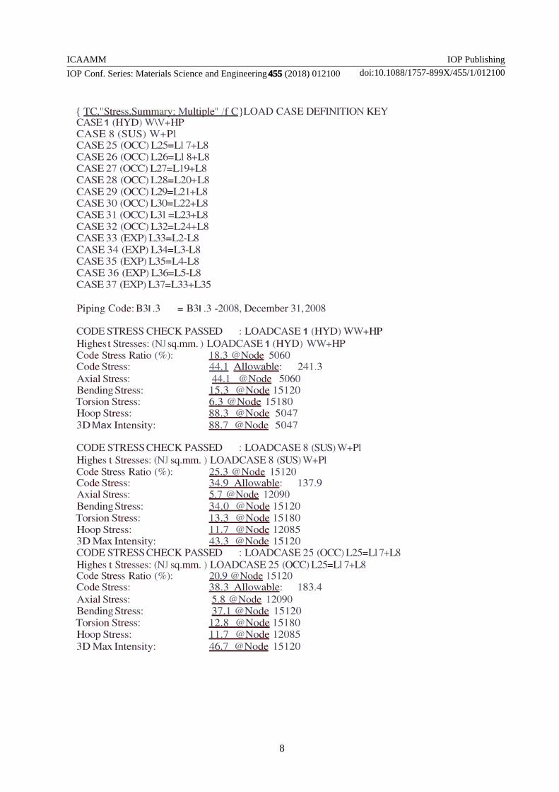
ICAAMM
IOP Conf Series Materials Science and Engineering455 (2018) 012100
IOP Publishing
doi1010881757-899X4551012100
8
TCStressSummary Multiple f CLOAD CASE DEFINITION KEY CASE 1 (HYD) WV+HP CASE 8 (SUS) W+Pl CASE 25 (OCC) L25=Ll 7+L8 CASE 26 (OCC) L26=Ll 8+L8 CASE 27 (OCC) L27=L19+L8 CASE 28 (OCC) L28=L20+L8 CASE 29 (OCC) L29=L21+L8 CASE 30 (OCC) L30=L22+L8 CASE 31 (OCC) L3l =L23+L8 CASE 32 (OCC) L32=L24+L8 CASE 33 (EXP) L33=L2-L8 CASE 34 (EXP) L34=L3-L8 CASE 35 (EXP) L35=L4-L8 CASE 36 (EXP) L36=L5-L8 CASE 37 (EXP) L37=L33+L35
Piping Code B3l 3 = B3l 3 -2008 December 31 2008
CODE STRESS CHECK PASSED LOADCASE 1 (HYD) WW+HP Highes t Stresses (NJ sqmm ) LOADCASE 1 (HYD) WW+HP Code Stress Ratio () 183 Node 5060 Code Stress 441 Allowable 2413 Axial Stress 441 Node 5060 Bending Stress 153 Node 15120 Torsion Stress 63 Node 15180 Hoop Stress 883 Node 5047 3D Max Intensity 887 Node 5047
CODE STRESS CHECK PASSED LOADCASE 8 (SUS) W+Pl Highes t Stresses (NJ sqmm ) LOADCASE 8 (SUS) W+Pl Code Stress Ratio () 253 Node 15120 Code Stress 349 Allowable 1379 Axial Stress 57 Node 12090 Bending Stress 340 Node 15120 Torsion Stress 133 Node 15180 Hoop Stress 117 Node 12085 3D Max Intensity 433 Node 15120 CODE STRESS CHECK PASSED LOADCASE 25 (OCC) L25=Ll 7+L8 Highes t Stresses (NJ sqmm ) LOADCASE 25 (OCC) L25=Ll 7+L8 Code Stress Ratio () 209 Node 15120 Code Stress 383 Allowable 1834 Axial Stress 58 Node 12090 Bending Stress 371 Node 15120 Torsion Stress 128 Node 15180 Hoop Stress 117 Node 12085 3D Max Intensity 467 Node 15120
ICAAMM
IOP Conf Series Materials Science and Engineering455 (2018) 012100
IOP Publishing
doi1010881757-899X4551012100
9
CODE STRESS CHECK PASSED LOADCASE 26 (OCC) L26=L18+L8 Highes t Stresses (NJ sqmm ) LOADCASE 26 (OCC) L26=L18+L8 Code Stress Ratio () 212 Node 15120 Code Stress 388 Allowable 1834 Axial Stress 57 Node 12090 Bending Stress 372 Node 15120 Torsion Stress 138 Node 15180 Hoop Stress 117 Node 12085 3D Max Intensity 474 Node 15120
CODE STRESS CHECK PASSED LOADCASE 27 (OCC) L27=L19+L8 Highes t Stresses (NJ sqmm ) LOADCASE 27 (OCC) L27=L19+L8 Code Stress Ratio () 333 Node 15120 Code Stress 611 Allowable 1834 Axial Stress 58 Node 12090 Bending Stress 586 Node 15120 Torsion Stress 165 Node 15120 Hoop Stress 117 Node 12085 3D Max Intensity 733 Node 15180
CODE STRESS CHECK PASSED LOADCASE 28 (OCC) L28=L20+L8 Highes t Stresses (NJ sqmm ) LOADCASE 28 (OCC) L28=L20+L8 Code Stress Ratio () 299 Node 15120 Code Stress 549 Allowable 1834 Axial Stress 58 Node 12090 Bending Stress 538 Node 15120 Torsion Stress 147 Node 15180 Hoop Stress 117 Node 12085 3D Max Intensity 643 Node 15120
CODE STRESS CHECK PASSED LOADCASE 29 (OCC) L29=L21+L8 Highes t Stresses (NJ sqmm ) LOADCASE 29 (OCC) L29=L21+L8 Code Stress Ratio () 491 Node 15120 Code Stress 900 Allowable 1834 Axial Stress 58 Node 12085 Bending Stress 842 Node 12040 Torsion Stress 192 Node 11260 Hoop Stress 117 Node 12085 3D Max Intensity 987 Node 15120
ICAAMM
IOP Conf Series Materials Science and Engineering455 (2018) 012100
IOP Publishing
doi1010881757-899X4551012100
10
CODE STRESS CHECK PASSED LOADCASE 30 (OCC) L30=L22+L8 Highes t Stresses (NJ sqmm ) LOADCASE 30 (OCC) L30=L22+L8 Code Stress Ratio () 483 Node 15120 Code Stress 886 Allowable 1834 Axial Stress 59 Node 12040 Bending Stress 837 Node 12040 Torsion Stress 171 Node 11260 Hoop Stress 117 Node 12085 3D Max Intensity 973 Node 15120
CODE STRESS CHECK PASSED LOADCASE 31 (OCC) L3l =L23+L8 Highes t Stresses (NJ sqmm ) LOADCASE 31 (OCC) L3l =L23+L8 Code Stress Ratio () 218 Node 15120 Code Stress 399 Allowable 1834 Axial Stress 57 Node 12090 Bending Stress 388 Node 15120 Torsion Stress 145 Node 15180 Hoop Stress 117 Node 12085 3D Max Intensity 485 Node 15120
CODE STRESS CHECK PASSED LOADCASE 32 (OCC) L32=L24+L8 Highes t Stresses (NJ sqmm ) LOADCASE 32 (OCC) L32=L24+L8 Code Stress Ratio () 277 Node 15120 Code Stress 508 Allowable 1834 Axial Stress 57 Node 12090 Bending Stress 496 Node 15120 Torsion Stress 146 Node 15180 Hoop Stress 117 Node 12085 3D Max Intensity 595 Node 15120
CODE STRESS CHECK PASSED LOADCASE 33 (EXP) L33=L2-L8 Highes t Stresses (NJ sqmm ) LOADCASE 33 (EXP) L33=L2-L8 Code Stress Ratio () 107 Node 12040 Code Stress 369 Allowable 3447 Axial Stress 20 Node 10040 Bending Stress 353 Node 12040 Torsion Stress 52 Node 14998 Hoop Stress 00 Node 10020 3D Max Intensity 710 Node 12040
ICAAMM
IOP Conf Series Materials Science and Engineering455 (2018) 012100
IOP Publishing
doi1010881757-899X4551012100
11
CODE STRESS CHECK PASSED LOADCASE 34 (EXP) L34=L3-L8 Highes t Stresses (NJ sqmm ) LOADCASE 34 (EXP) L34=L3-L8 Code Stress Ratio () 22 Node 12040 Code Stress 76 Allowable 3447 Axial Stress 14 Node 10040 Bending Stress 73 Node 12040 Torsion Stress 13 Node 11420 Hoop Stress 00 Node 10020 3D Max Intensity 146 Node 12040
CODE STRESS CHECK PASSED LOADCASE 35 (EXP) L35=L4-L8 Highes t Stresses (NJ sqmm ) LOADCASE 35 (EXP) L35=L4-L8 code Stress Ratio () 68 Node 10706 Code Stress 234 Allowable 3447 Axial Stress 19 Node 10040 Bending Stress 227 Node 10706 Torsion Stress 33 Node 11420 Hoop Stress 00 Node 10020 3D Max Intensity 413 Node 11598
CODE STRESS CHECK PASSED LOADCASE 36 (EXP) L36=L5-L8 Highes t Stresses (NJ sqmm ) LOADCASE 36 (EXP) L36=L5-L8 CodeStress Ratio () 24 Node 15670 Code Stress 82 Allowable 3447 Axial Stress 03 Node 15180 Bending Stress 81 Node 15670 Torsion Stress 10 Node 10800 Hoop Stress 00 Node 10020 3D Max Intensity 153 Node 15670
CODE STRESS CHECK PASSED LOADCASE 37 (EXP) L37=L33+L35 Highes t Stresses (NJ sqmm ) LOADCASE 37 (EXP) L37=L33+L35 Code Stress Ratio () 155 Node 10300 Code Stress 534 Allowable 3447 Axial Stress 39 Node 10040 Bending Stress 525 Node 10300 Torsion Stress 77 Node 11420 Hoop Stress 00 Node 10020 3D Max Intensity 908 Node 12
ICAAMM
IOP Conf Series Materials Science and Engineering455 (2018) 012100
IOP Publishing
doi1010881757-899X4551012100
12
Table 3 LOAD CAS ES AT NODE 10560
NODE
LOAD CASE
FX N
FY N
FZ N
MX Nm
MY Nm
MZ Nm
DXmm DYmm
DZmm 16(OPE) 0 -985 0 0 0 0 0078 -0000 0243
MAX - 620L14
- 1696L4
-507L4
3000L13
- 0000L4
1596LS
10560
RIGIT + Y
1(HYD) 163 -2201 -46 0 0 0 0001 -0000 0000 2(OPE) -189 -1767 495 0 0 0 -0377 -0000 0989 3(OPE) -150 -3082 912 0 0 0 -0022 -0000 0131 4(OPE) 0 0 0 0 0 0 0305 0227 -0718 5(OPE) 0 -2751 0 0 0 0 -0324 -0000 0132 6(OPE) -181 -3114 916 0 0 0 -0026 -0000 0131 7(OPE) -176 -2625 768 0 0 0 -0016 -0000 0068 8(OPE) 156 -2138 -41 0 0 0 0001 -0000 0000 9(OPE) 403 -2755 722 0 0 0 0073 -0000 0132 10(OPE) -666 -2932 574 0 0 0 -0153 -0000 0132 11(OPE) -126 -2889 857 0 0 0 -0019 -0000 0132 12(OPE) -183 -3291 970 0 0 0 -0025 -0000 0131 13(OPE) 0 -2661 0 0 0 0 2716 -0000 0132 14(OPE) 0 -2819 0 0 0 0 -2841 -0000 0132 15(OPE) 0 -2710 0 0 0 0 -0645 -0000 0133 16(OPE) 0 -2791 0 0 0 0 -0004 -0000 0132
MAX - 666L10
- 329L12
970L12
- 2841L14 0227L4
0989L2
ICAAMM
IOP Conf Series Materials Science and Engineering455 (2018) 012100
IOP Publishing
doi1010881757-899X4551012100
13
Table 4 FORCES AND MOMENTS PUMP NOZZLE-DN1(2rdquo) 12280 NODE
Table 5 FORCES AND MOMENTS PUMP NOZZLE-DN1(3rdquo) 10820 NODE
Table 6 FORCES AND MOMENTS PUMP NOZZLE-DN1(3rdquo) 11280 NODE
Table 7 FORCES AND MOMENTS VESS EL NOZZLE-N2(3rdquo) 5025 NODE
ICAAMM
IOP Conf Series Materials Science and Engineering455 (2018) 012100
IOP Publishing
doi1010881757-899X4551012100
14
7 CONCLUSION
Stress Analysis of pump piping system between pump and vessel is made as safe by providing an expansion loop As per ASME 313 Pump and Vessel nozzles are within theAllowable Stress Nozzle loads Restraint loads all are within the limit after providing an expansion loop as per Standards
REFERENCES [1] GA Antaki Piping amp Pipeline Engineering Design Construction Maintenance Integrity amp Repair CRC Press 2003 [2] Roy A Parisher Pipe Drafting amp Design Gulf Professional Publishing 01- Jan- 2012-07-29 [3]Mohinder L Nayyar Piping Hand book McGraw Hill seventh edition 2000 [4] LANL Engineering Standards Manual PD342 ASME B313 2004 ndashEdition
[5]J Okrajni K Mutwil and M Cieoela Chemical pipelines material fatigue Departments of Mechanics Of Materials Silesian University of Technology Poland [6]HoussamToutanji Sean Dempse Stress modeling of pipelines strengthened with advanced composites materials Thin-Walled Structures Volume 39 Issue 2 February 2001 Pages 153-165 [7] Sam Kannapan Introduction to Pipe Stress Analysis Pages 123-125
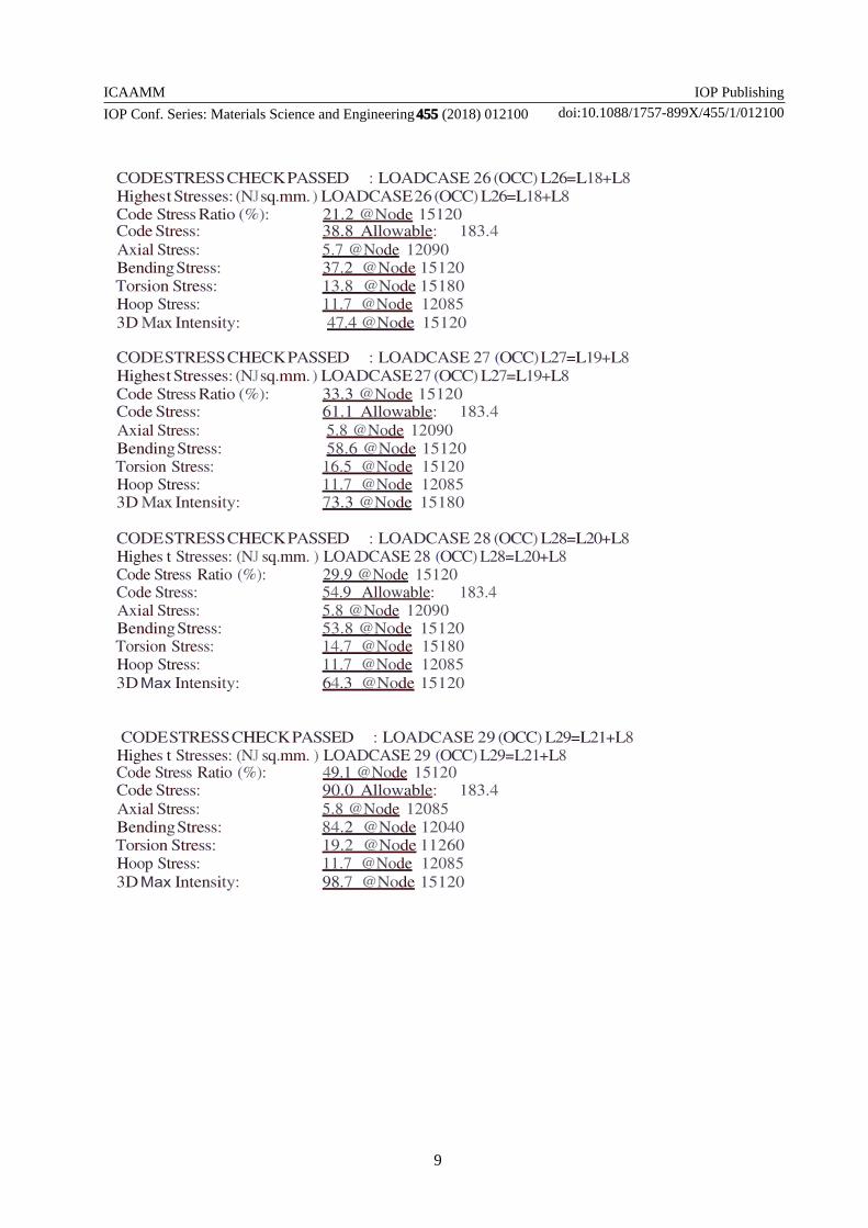
ICAAMM
IOP Conf Series Materials Science and Engineering455 (2018) 012100
IOP Publishing
doi1010881757-899X4551012100
9
CODE STRESS CHECK PASSED LOADCASE 26 (OCC) L26=L18+L8 Highes t Stresses (NJ sqmm ) LOADCASE 26 (OCC) L26=L18+L8 Code Stress Ratio () 212 Node 15120 Code Stress 388 Allowable 1834 Axial Stress 57 Node 12090 Bending Stress 372 Node 15120 Torsion Stress 138 Node 15180 Hoop Stress 117 Node 12085 3D Max Intensity 474 Node 15120
CODE STRESS CHECK PASSED LOADCASE 27 (OCC) L27=L19+L8 Highes t Stresses (NJ sqmm ) LOADCASE 27 (OCC) L27=L19+L8 Code Stress Ratio () 333 Node 15120 Code Stress 611 Allowable 1834 Axial Stress 58 Node 12090 Bending Stress 586 Node 15120 Torsion Stress 165 Node 15120 Hoop Stress 117 Node 12085 3D Max Intensity 733 Node 15180
CODE STRESS CHECK PASSED LOADCASE 28 (OCC) L28=L20+L8 Highes t Stresses (NJ sqmm ) LOADCASE 28 (OCC) L28=L20+L8 Code Stress Ratio () 299 Node 15120 Code Stress 549 Allowable 1834 Axial Stress 58 Node 12090 Bending Stress 538 Node 15120 Torsion Stress 147 Node 15180 Hoop Stress 117 Node 12085 3D Max Intensity 643 Node 15120
CODE STRESS CHECK PASSED LOADCASE 29 (OCC) L29=L21+L8 Highes t Stresses (NJ sqmm ) LOADCASE 29 (OCC) L29=L21+L8 Code Stress Ratio () 491 Node 15120 Code Stress 900 Allowable 1834 Axial Stress 58 Node 12085 Bending Stress 842 Node 12040 Torsion Stress 192 Node 11260 Hoop Stress 117 Node 12085 3D Max Intensity 987 Node 15120
ICAAMM
IOP Conf Series Materials Science and Engineering455 (2018) 012100
IOP Publishing
doi1010881757-899X4551012100
10
CODE STRESS CHECK PASSED LOADCASE 30 (OCC) L30=L22+L8 Highes t Stresses (NJ sqmm ) LOADCASE 30 (OCC) L30=L22+L8 Code Stress Ratio () 483 Node 15120 Code Stress 886 Allowable 1834 Axial Stress 59 Node 12040 Bending Stress 837 Node 12040 Torsion Stress 171 Node 11260 Hoop Stress 117 Node 12085 3D Max Intensity 973 Node 15120
CODE STRESS CHECK PASSED LOADCASE 31 (OCC) L3l =L23+L8 Highes t Stresses (NJ sqmm ) LOADCASE 31 (OCC) L3l =L23+L8 Code Stress Ratio () 218 Node 15120 Code Stress 399 Allowable 1834 Axial Stress 57 Node 12090 Bending Stress 388 Node 15120 Torsion Stress 145 Node 15180 Hoop Stress 117 Node 12085 3D Max Intensity 485 Node 15120
CODE STRESS CHECK PASSED LOADCASE 32 (OCC) L32=L24+L8 Highes t Stresses (NJ sqmm ) LOADCASE 32 (OCC) L32=L24+L8 Code Stress Ratio () 277 Node 15120 Code Stress 508 Allowable 1834 Axial Stress 57 Node 12090 Bending Stress 496 Node 15120 Torsion Stress 146 Node 15180 Hoop Stress 117 Node 12085 3D Max Intensity 595 Node 15120
CODE STRESS CHECK PASSED LOADCASE 33 (EXP) L33=L2-L8 Highes t Stresses (NJ sqmm ) LOADCASE 33 (EXP) L33=L2-L8 Code Stress Ratio () 107 Node 12040 Code Stress 369 Allowable 3447 Axial Stress 20 Node 10040 Bending Stress 353 Node 12040 Torsion Stress 52 Node 14998 Hoop Stress 00 Node 10020 3D Max Intensity 710 Node 12040
ICAAMM
IOP Conf Series Materials Science and Engineering455 (2018) 012100
IOP Publishing
doi1010881757-899X4551012100
11
CODE STRESS CHECK PASSED LOADCASE 34 (EXP) L34=L3-L8 Highes t Stresses (NJ sqmm ) LOADCASE 34 (EXP) L34=L3-L8 Code Stress Ratio () 22 Node 12040 Code Stress 76 Allowable 3447 Axial Stress 14 Node 10040 Bending Stress 73 Node 12040 Torsion Stress 13 Node 11420 Hoop Stress 00 Node 10020 3D Max Intensity 146 Node 12040
CODE STRESS CHECK PASSED LOADCASE 35 (EXP) L35=L4-L8 Highes t Stresses (NJ sqmm ) LOADCASE 35 (EXP) L35=L4-L8 code Stress Ratio () 68 Node 10706 Code Stress 234 Allowable 3447 Axial Stress 19 Node 10040 Bending Stress 227 Node 10706 Torsion Stress 33 Node 11420 Hoop Stress 00 Node 10020 3D Max Intensity 413 Node 11598
CODE STRESS CHECK PASSED LOADCASE 36 (EXP) L36=L5-L8 Highes t Stresses (NJ sqmm ) LOADCASE 36 (EXP) L36=L5-L8 CodeStress Ratio () 24 Node 15670 Code Stress 82 Allowable 3447 Axial Stress 03 Node 15180 Bending Stress 81 Node 15670 Torsion Stress 10 Node 10800 Hoop Stress 00 Node 10020 3D Max Intensity 153 Node 15670
CODE STRESS CHECK PASSED LOADCASE 37 (EXP) L37=L33+L35 Highes t Stresses (NJ sqmm ) LOADCASE 37 (EXP) L37=L33+L35 Code Stress Ratio () 155 Node 10300 Code Stress 534 Allowable 3447 Axial Stress 39 Node 10040 Bending Stress 525 Node 10300 Torsion Stress 77 Node 11420 Hoop Stress 00 Node 10020 3D Max Intensity 908 Node 12
ICAAMM
IOP Conf Series Materials Science and Engineering455 (2018) 012100
IOP Publishing
doi1010881757-899X4551012100
12
Table 3 LOAD CAS ES AT NODE 10560
NODE
LOAD CASE
FX N
FY N
FZ N
MX Nm
MY Nm
MZ Nm
DXmm DYmm
DZmm 16(OPE) 0 -985 0 0 0 0 0078 -0000 0243
MAX - 620L14
- 1696L4
-507L4
3000L13
- 0000L4
1596LS
10560
RIGIT + Y
1(HYD) 163 -2201 -46 0 0 0 0001 -0000 0000 2(OPE) -189 -1767 495 0 0 0 -0377 -0000 0989 3(OPE) -150 -3082 912 0 0 0 -0022 -0000 0131 4(OPE) 0 0 0 0 0 0 0305 0227 -0718 5(OPE) 0 -2751 0 0 0 0 -0324 -0000 0132 6(OPE) -181 -3114 916 0 0 0 -0026 -0000 0131 7(OPE) -176 -2625 768 0 0 0 -0016 -0000 0068 8(OPE) 156 -2138 -41 0 0 0 0001 -0000 0000 9(OPE) 403 -2755 722 0 0 0 0073 -0000 0132 10(OPE) -666 -2932 574 0 0 0 -0153 -0000 0132 11(OPE) -126 -2889 857 0 0 0 -0019 -0000 0132 12(OPE) -183 -3291 970 0 0 0 -0025 -0000 0131 13(OPE) 0 -2661 0 0 0 0 2716 -0000 0132 14(OPE) 0 -2819 0 0 0 0 -2841 -0000 0132 15(OPE) 0 -2710 0 0 0 0 -0645 -0000 0133 16(OPE) 0 -2791 0 0 0 0 -0004 -0000 0132
MAX - 666L10
- 329L12
970L12
- 2841L14 0227L4
0989L2
ICAAMM
IOP Conf Series Materials Science and Engineering455 (2018) 012100
IOP Publishing
doi1010881757-899X4551012100
13
Table 4 FORCES AND MOMENTS PUMP NOZZLE-DN1(2rdquo) 12280 NODE
Table 5 FORCES AND MOMENTS PUMP NOZZLE-DN1(3rdquo) 10820 NODE
Table 6 FORCES AND MOMENTS PUMP NOZZLE-DN1(3rdquo) 11280 NODE
Table 7 FORCES AND MOMENTS VESS EL NOZZLE-N2(3rdquo) 5025 NODE
ICAAMM
IOP Conf Series Materials Science and Engineering455 (2018) 012100
IOP Publishing
doi1010881757-899X4551012100
14
7 CONCLUSION
Stress Analysis of pump piping system between pump and vessel is made as safe by providing an expansion loop As per ASME 313 Pump and Vessel nozzles are within theAllowable Stress Nozzle loads Restraint loads all are within the limit after providing an expansion loop as per Standards
REFERENCES [1] GA Antaki Piping amp Pipeline Engineering Design Construction Maintenance Integrity amp Repair CRC Press 2003 [2] Roy A Parisher Pipe Drafting amp Design Gulf Professional Publishing 01- Jan- 2012-07-29 [3]Mohinder L Nayyar Piping Hand book McGraw Hill seventh edition 2000 [4] LANL Engineering Standards Manual PD342 ASME B313 2004 ndashEdition
[5]J Okrajni K Mutwil and M Cieoela Chemical pipelines material fatigue Departments of Mechanics Of Materials Silesian University of Technology Poland [6]HoussamToutanji Sean Dempse Stress modeling of pipelines strengthened with advanced composites materials Thin-Walled Structures Volume 39 Issue 2 February 2001 Pages 153-165 [7] Sam Kannapan Introduction to Pipe Stress Analysis Pages 123-125
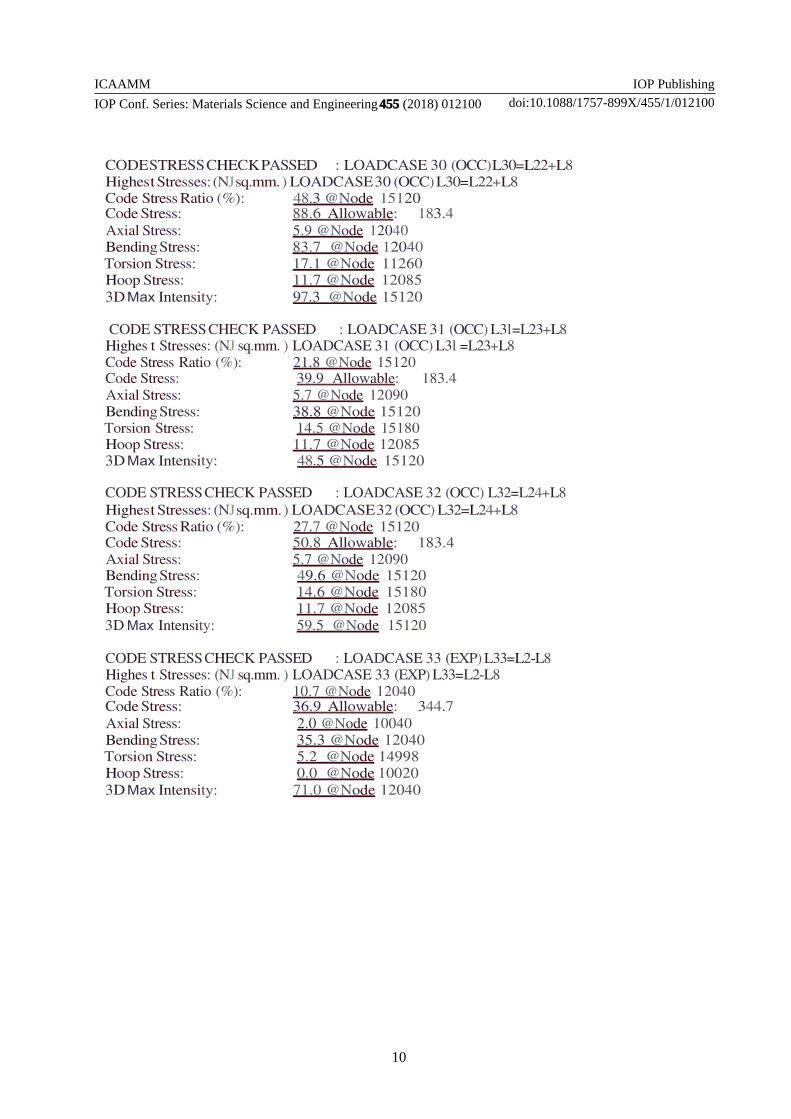
ICAAMM
IOP Conf Series Materials Science and Engineering455 (2018) 012100
IOP Publishing
doi1010881757-899X4551012100
14
7 CONCLUSION
Stress Analysis of pump piping system between pump and vessel is made as safe by providing an expansion loop As per ASME 313 Pump and Vessel nozzles are within theAllowable Stress Nozzle loads Restraint loads all are within the limit after providing an expansion loop as per Standards
REFERENCES [1] GA Antaki Piping amp Pipeline Engineering Design Construction Maintenance Integrity amp Repair CRC Press 2003 [2] Roy A Parisher Pipe Drafting amp Design Gulf Professional Publishing 01- Jan- 2012-07-29 [3]Mohinder L Nayyar Piping Hand book McGraw Hill seventh edition 2000 [4] LANL Engineering Standards Manual PD342 ASME B313 2004 ndashEdition
[5]J Okrajni K Mutwil and M Cieoela Chemical pipelines material fatigue Departments of Mechanics Of Materials Silesian University of Technology Poland [6]HoussamToutanji Sean Dempse Stress modeling of pipelines strengthened with advanced composites materials Thin-Walled Structures Volume 39 Issue 2 February 2001 Pages 153-165 [7] Sam Kannapan Introduction to Pipe Stress Analysis Pages 123-125
Recommended