This manual is to be given
to the end user
VOLTAGE REGULATOR R452
R 452 X2Z1X1Z2E+E-
J1 +-
t
(12V - 10A)
Exciter field
Isolated DCpower supply
~ 10 ohms
Installation and maintenance
Ref. 3563 GB - 4.33 / a - 01.02

2
INSTALLATION AND MAINTENANCE
VOLTAGE REGULATOR R452
LEROY-SOMER
Ref. 3563 GB - 4.33 / a - 01.02
WARNING
IN ORDER TO AVOID ANY HARM TO EITHER PERSONNEL OR THE INSTALLATION, THIS DEVICE MUST ONLY BE SET UP BY
A QUALIFIED ENGINEER.
CAUTION
DO NOT USE HIGH-VOLTAGE MEASURING APPARATUS. INCORRECT USE OF CERTAIN APPARATUS MAY LEAD TO DESTRUCTION OF THE SEMICONDUCTORS INCLUDED IN
THE VOLTAGE REGULATOR.
NOTE
THE CONNECTION DIAGRAMS IN THIS MANUAL ARE PROVIDED FOR INFORMATION ONLY. FOR ACTUAL
CONNECTION, SEE THE DIAGRAMS SUPPLIED WITH THE ALTERNATOR.
CAUTION
1) WHILE THE ALTERNATOR IS AT A STANDSTILL, MAINS VOLTAGE MAY REAPPEAR AT THE MODULE VOLTAGE
SENSING TERMINALS.
LETHAL DANGER
2) DO NOT PERFORM DIELECTRIC TESTS WITHOUT DISCONNECTING THE MODULE AND ITS ASSOCIATED
VOLTAGE REGULATOR.
RISK OF DESTRUCTION

3
INSTALLATION AND MAINTENANCE
VOLTAGE REGULATOR R452
CONTENTS
LEROY-SOMER
Ref. 3563 GB - 4.33 / a - 01.02
1 - Presentation of the R 452 .................................................................................................................. 4
1.1 - Application ................................................................................................................................ 41.2 - Description ............................................................................................................................... 41.3 - Electrical characteristics............................................................................................................ 5
1.3.1 - Operating diagram ....................................................................................................... 51.3.2 - Sensing ........................................................................................................................ 61.3.3 - Voltage accuracy ......................................................................................................... 61.3.4 - Voltage setting ............................................................................................................. 61.3.5 - Power supply ............................................................................................................... 61.3.6 - Output power ............................................................................................................... 61.3.7 - Quadrature droop (1F) ................................................................................................. 61.3.8 - Frequency/Underspeed ............................................................................................... 61.3.9 - Stability ........................................................................................................................ 81.3.10 - Limiting the excitation current Iex .............................................................................. 81.3.11 - Protection ................................................................................................................... 81.3.12 - Voltage build-up ......................................................................................................... 81.3.13 - Power usage .............................................................................................................. 81.3.14 - De-energising ............................................................................................................ 8
1.4 - Environment ............................................................................................................................. 8
2 - R 726: Regulation of power factor (2F) and mains voltage sensing (3F) ...................................... 9
2.1 - Potentiometers ......................................................................................................................... 92.2 - Operating diagram ................................................................................................................. 10
3 - Typical diagrams .............................................................................................................................. 11
3.1 - AREP 1F LV excitation ........................................................................................................... 113.2 - AREP 1F MV excitation .......................................................................................................... 123.3 - AREP 3F LV excitation ........................................................................................................... 133.4 - AREP 3F MV excitation .......................................................................................................... 143.5 - 1F LV shunt + booster excitation ........................................................................................... 153.6 - 1F LV PMG excitation ............................................................................................................ 16
4 - Commissioning ................................................................................................................................. 17
4.1 - For standalone regulation ...................................................................................................... 174.2 - For 1F regulation (parallel operation between alternators) .................................................... 174.3 - For 2F regulation (regulation of power factor) and 3F regulation (voltage match circuit) ....... 17
5 - Troubleshooting ............................................................................................................................... 19
5.1 - Checking the windings and rotating diodes using a separate excitation ................................ 195.2 - Static checking of the regulator .............................................................................................. 195.3 - Troubleshooting table ............................................................................................................. 20
5.3.1 - For 1F regulation, parallel operation between alternators ........................................ 205.3.2 - For 2F and 3F ............................................................................................................ 225.3.3 - Checking the alternator using a separate excitation .................................................. 22
5.4 - Replacing the regulator with a spare voltage regulator .......................................................... 22

4
INSTALLATION AND MAINTENANCE
VOLTAGE REGULATOR R452
P
RESENTATION
OF
THE
R 452
LEROY-SOMER
Ref. 3563 GB - 4.33 / a - 01.02
1 - PRESENTATION OF THE R 452
1.1 - application
The R 452 regulator is of a shunt type. It is designed to fit as standard on alternators from the LSA 46.2 to the LSA 54, and is used to replace R 448 or R 449 AVRs for any application with high load impacts, leading to load reconnection difficulties for the generator set. It can be supplied with power either by a power VT, or by the AREP excitation system, or by a single-phase or 3-phase PMG.Using the R 726 external module, the regulator can control the power factor (2F) and can match the alternator voltage to the mains voltage (3F).
1.2 - description
The electronic components mounted in a plastic casing are sealed with opaque elastomer. Connection is via 2 connectors (male ''Faston'' lugs 6.3).The regulator includes:
-
A main terminal block (10 terminals) J1- A secondary terminal block (5 terminals) J2- A frequency selection terminal block (3 terminals) J3- A droop potentiometer P1- A voltage potentiometer P2- A stability potentiometer - Integral P3- An underspeed potentiometer P4- A maximum excitation potentiometer P5- A LAM potentiometer P6- A kU/F potentiometer P7- A stability potentiometer - (proportional) P8- A stability potentiometer - (derivative) P9- A sensing selection jumper ST1 (Single/3-phase with an external module)- A response time jumper ST2- A frequency selection jumper ST3- An external voltage setting jumper ST4- A LAM (load adjustment module) jumper ST5
Two fuses (F1 and F2) are connected to this regulator; they are mounted in the alternator on terminal block C.Type: gG 10/38 16A 500V.
Simplified diagram of a potentiometer:
To adjust the potentiometer, check the actual position of the potentiometer stop.
50
10
Stop
ST3 50Hz 60Hz
4 x Ø5.8 x 175 x 115
200 x 140 mm
X2
X1Z2E+E-0V110220380
Z1
L2(V)
L3 (W)
340-520V
170-260V
R452
P5
P2
P4
P3
ST2
ST5
R731
C.T.
ST4
ST4
Option
S1 S2
P1ST1
normal
5+ 6 -
85-140V
Option Option
Responsetime
With LAM Without LAM
Single phasedetection
3-phase detection
Excitationceiling
Frequency
Underspeed
Stability
External potentiometerfor voltage adjustmentor for R 726 connection
Voltage
Quad. droop
Exciter field
Supply
Stability(derivative)
Stability(proportio.) P9 J2
J1
J3
P8
P6 LAM
P7 kU/F
rapid

5
INSTALLATION AND MAINTENANCE
VOLTAGE REGULATOR R452
P
RESENTATION
OF
THE
R 452
LEROY-SOMER
Ref. 3563 GB - 4.33 / a - 01.02
1.3 - electrical characteristics
1.3.1 - operating diagram

6
INSTALLATION AND MAINTENANCE
VOLTAGE REGULATOR R452
P
RESENTATION
OF
THE
R 452
LEROY-SOMER
Ref. 3563 GB - 4.33 / a - 01.02
1.3.2 - sensing
The sensing is single-phase and is isolated using an internal transformer.Sensing VA: 5VAJ1 connector, input voltages:Terminals 0-110V voltage range from 85 to 130VTerminals 0-220V voltage range from 170 to 260VTerminals 0-380V voltage range from 340 to 520V
1.3.3 - voltage accuracy
The voltage accuracy is +/- 0,5%Un, steady state, linear load.
1.3.4 - voltage adjustment
The voltage is adjusted either using an internal potentiometer P2, with a voltage range of +/- 10%Un, or using an external potentiometer (as an option).The voltage is minimum when internal potentiometer P2 has been rotated fully anti-clockwise.
Connecting the external potentiometer: External potentiometer 470W 3W: Voltage range +/- 5 %UnExternal potentiometer 1kW 3W: Voltage range +/-10 %UnRemove the ST4 jumper and connect the external potentiometer as shown in the diagram below. If a regulator is built into the terminal box, remove the ST10 jumper from terminal block C and connect the external potentiometer.
1.3.5 - power supply
The power can be supplied: using 2 independent auxiliary windings integrated in the alternator stator (AREP excitation) or using a single or3-phase power VT or using a single or 3-phase PMG.The single or 3-phase voltage must not exceed 240V AC.
1.3.6 - output power
The output power is 7A 63V under normal conditions and 15A for 10s under overload conditions.
1.3.7 - quadrature droop (1F)
Quadrature droop is achieved using a parallel operation CT (In/1A, 10VA Cl1). The voltage dip can be adjusted using potentiometer P1. The voltage range is 5%Un for Pn PF 0.8. The quadrature droop is at 0 when potentiometer P1 has been rotated fully anti-clockwise.
1.3.8 - frequency/underspeed
Definition of underspeed potentiometers:- P4: setting the knee-point - P6: setting the LAM - P7: setting the kU/F
Selection of underfrequency threshold using the ST3 jumper
U/F:
Action threshold adjustable using potentiometer P4
To avoid voltage oscillations, the trip threshold of the "LAM" function should be set approximately 2 Hz below the lowest frequency in normal operation.(Adjustable using potentiometer P4).
- Setting the kU/F: Potentiometer P7 is used for this purpose.It can be used to adjust the underspeed slope from U/F to 3U/F.
LAM:
When it leaves the factory, the regulator is configured with the LAM activated.It is disabled by disconnecting the ST5 jumper, and operation is then the standard U/F.- Role of the "LAM" (load adjustment module).When a load is applied, the speed of rotation of the generatorset decreases. When it falls below the preset frequency threshold, the "LAM" causes the voltage to drop by approximately 15 %. This in turn reduces the active load scale applied by approximately 25 %, until the speed returns to its rated value.The LAM can therefore either be used to reduce the speed variation (frequency) and its duration for a given applied load, or to increase the possible applied load for one speed variation (turbo-charged engines).Pour régler le LAM procéder comme indiqué ci-dessous :- P6 (LAM) : position médiane (LAM
#
10%)- P7 (kU/F) : position médiane (2U/F)Appliquer la charge, enregistrer la vitesse et la tension.En fonction des résultats, agir d’abord sur :- P7 (kU/F) : position système horaire (34/F)Refaire l’essai d’application de la charge, si nécessaire, agir ensuite sur :- P6 (LAM) : 3/4 horaire (LAM = 15%)Puis si nécessaire à nouveau sur :- P6 (LAM) : position extrème horaire (LAM = 20%)
- Setting the LAM:Potentiometer P6 is used for this purpose.It can be used to adjust the LAM from 5 to 20 %Un.
P2
J2
ST4
J2
ST4Rhe
Internal External
Voltage setting : ST4
P1
ST3J3
ST3J350 Hz 60 Hz
P4
50
10
U/F
3U/F
2U/F
50
10
5%Un
20%Un
10%Un
LAM
UN
048 or 58 Hz
0.85 UN
Frequency
Voltage
P2
P6
P4
P7
U/f
50 or 60 Hz
fC fN
Under frequency and LAM
VoltageST5 cut
ST3

7
INSTALLATION AND MAINTENANCE
VOLTAGE REGULATOR R452
P
RESENTATION
OF
THE
R 452
LEROY-SOMER
Ref. 3563 GB - 4.33 / a - 01.02
- Typical effects of a ''LAM'' with a diesel engine.
UN
0
0.9
0.8
(U/f)
LAM
Transient voltage dip
0.9
0.8
Speed drop
"LAM" action
∆ P Load step
Time (s)
1 2 3
Load
on
the
shaf
t (k
W)
fN
w/o LAM (U/F only) with Lam
LAM
LAM
Voltage
Frequency
Load

8
INSTALLATION AND MAINTENANCE
VOLTAGE REGULATOR R452
P
RESENTATION
OF
THE
R 452
LEROY-SOMER
Ref. 3563 GB - 4.33 / a - 01.02
1.3.9 - stability
Definition of stability potentiometers:- P3: integrator- P8: proportional- P9: derivative- Standard position potentiometer positions: 5
Setting the stability:The stability is initially set on voltage build-up, with the alternator at rated speed, de-energised.At the start of the test, set all 3 potentiometers to 5.
Find the best position for P3:
Close the de-energisation contact and monitor the voltage making (overvoltage and oscillation) on build-up.De-energise the alternator (open the de-energisation contact).Set P3 to a different position from 5 and repeat voltage build-up.Repeat this test several times and select the position of P3 which produces the best voltage build-up, ie. without overvoltage and without oscillations.Retain this position for subsequent tests.
Find the best position for P8:
Perform the same tests as before.Select the position of P8 which produces the best voltage build-up.Retain this position for subsequent tests.
Find the best position for P9:
Perform the same tests as before.Select the position of P9 which produces the best voltage build-up.
Then do a test with load impact (or load shedding) andfine-tune the settings.
1.3.10 - limiting the excitation current iex
- Potentiometer P5 is used to adjust Iex limitation. Limitation of the excitation current is active for 10s. After this period of time, the excitation current is limited to 2A.The maximum limitation is 15A.The minimum limitation is when the potentiometer has been rotated fully anti-clockwise.In the absence of specification to the contrary, P5 is positioned at the clockwise limit.- Static adjustment of the max. excitation current.For this value, the static adjustment is possible when the alternator is stopped, which will not endanger the alternator or the installation.Disconnect power supply wires X1,X2 and Z1,Z2, and the voltage reference from the alternator (terminal block J1).Connect the mains power supply, 200 to 240V, as indicated (X1 and X2): 0-220V). Install a 20A D.C. ammeter in series with the exciter field.Turn P5 fully anti-clockwise, switch on the power supply (switch A).If there is no output current from the AVR, turn potentiometer P2 (voltage) clockwise until the ammeter indicates a stabilised current.Switch the power supply off and then on again, turn P5 clockwise until the required excitation current is reached (limited to 15A), (for precise adjustment contact Leroy-Somer).Checking the internal protection: Open switch (D): the excitation current should increase to its preset ceiling, remain at that level for 10s and then fall back automatically to a value less than 2A.
To reset, switch off the power supply by opening switch (A).Note: After setting the excitation ceiling using this procedure, re-adjust the voltage.
1.3.11 - protection
There are two fuses in the power section. They are fitted externally to the AVR but inside the alternator terminal box.Rating: gG 10/38 16A 500V
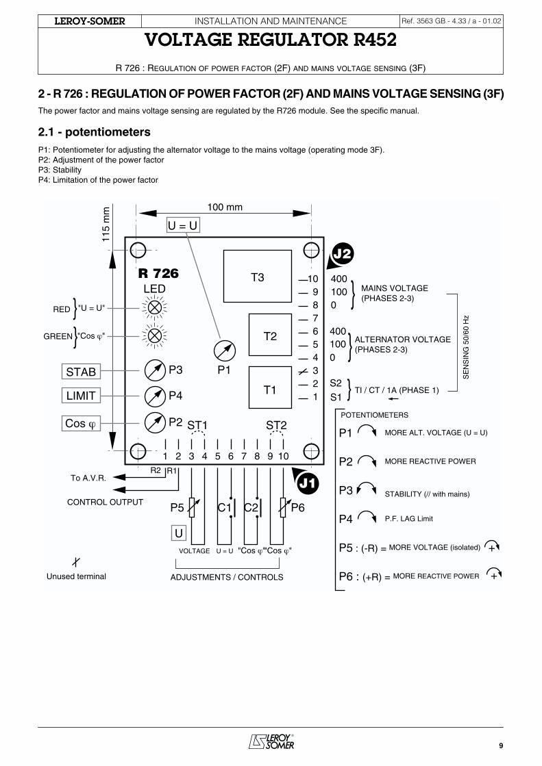
1.3.12 - voltage build-up
The voltage build-up is automatic (no overvoltage) from the residual magnetism.If there is no voltage build-up, a short pulse of continuous isolated voltage (12VDC), will usually remedy this. Otherwise, proceed in accordance with the diagram below to re-establish the residual magnetism:
1.3.13 - power usage
The power used by the R 449 is 30W, when the alternator is at rated power.
1.3.14 - de-energising
The regulator is de-energised by switching off its power supply.Contact rating: 15A, 250V AC
1.4 - environment
- Operating temperature: -20 ˚C to +70 ˚C- Storage temperature: -55 ˚C to +85 ˚C- Shocks on the base: 9g for the 3 right-angled directions- Vibrations: Less than 10Hz: 2mm half-peak amplitude10Hz to 100Hz: 100mm/sAbove 100Hz: 8g
Exciter field~ 10 ohms
R 452
X2Z1X1Z2E+E-
0V
220V380V
P2
P3
P4
P5
50Hz 60Hz
S1 S2
ST1
ST2
P1
ST3
ST5
Mains(Supply 50/60 Hz)
20A CC / DC
ST4
Max. excit.
Voltage
A+-
According to mains frequency
A
D
R 452 X2Z1X1Z2E+E-
J1 +-
t
(12V - 10A)
Exciter field
Isolated DCpower supply
~ 10 ohms
R 452
X2Z1X1Z2E+E-
Aux. windingsJ1
9
INSTALLATION AND MAINTENANCE
VOLTAGE REGULATOR R452
R 726 : R
EGULATION
OF
POWER
FACTOR
(2F)
AND
MAINS VOLTAGE SENSING (3F)
LEROY-SOMER Ref. 3563 GB - 4.33 / a - 01.02
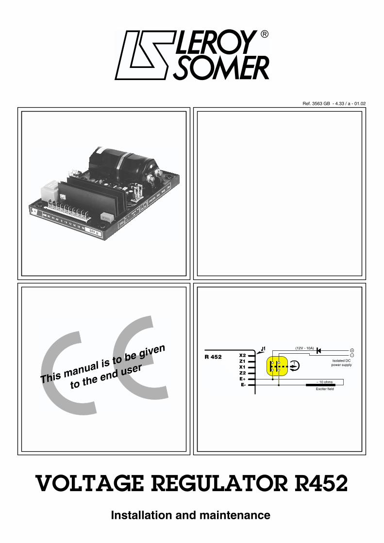
2 - R 726 : REGULATION OF POWER FACTOR (2F) AND MAINS VOLTAGE SENSING (3F)The power factor and mains voltage sensing are regulated by the R726 module. See the specific manual.
2.1 - potentiometers P1: Potentiometer for adjusting the alternator voltage to the mains voltage (operating mode 3F).P2: Adjustment of the power factorP3: StabilityP4: Limitation of the power factor
10987654321
400
0
S1S2
T3
T2
T1
1 2 3 4 5 6 7 8 9 10
LED
P3
P4
P1
ST1 ST2
MAINS VOLTAGE(PHASES 2-3)
ALTERNATOR VOLTAGE(PHASES 2-3)
RED
GREEN
"U = U"
"Cos j"
J1
P5 C1 C2 P6
UVOLTAGE U = U "Cos j" "Cos j"
J2
TI / CT / 1A (PHASE 1)LIMIT
To A.V.R.
P1
P2
P3
P4
P5 : (-R) =
P6 : (+R) =
MORE ALT. VOLTAGE (U = U)
MORE REACTIVE POWER
STABILITY (// with mains)
P.F. LAG Limit
MORE VOLTAGE (isolated)
MORE REACTIVE POWER
U = U
100 mm
115
mm
SE
NS
ING
50/
60 H
z
POTENTIOMETERS
+
+ADJUSTMENTS / CONTROLS
CONTROL OUTPUT
P2Cos j
STAB
R2 R1
Unused terminal
400100
100
0 R 726

10
INSTALLATION AND MAINTENANCE
VOLTAGE REGULATOR R452R 726 : REGULATION OF POWER FACTOR (2F) AND MAINS VOLTAGE SENSING (3F)
LEROY-SOMER Ref. 3563 GB - 4.33 / a - 01.02
2.2 - operating diagram

11
INSTALLATION AND MAINTENANCE
VOLTAGE REGULATOR R452
TYPICAL DIAGRAMS
LEROY-SOMER Ref. 3563 GB - 4.33 / a - 01.02
3 - TYPICAL DIAGRAMSThe following diagrams are supplied for information only and are not to be used in place of the actual alternator diagrams.
3.1 - AREP 1F LV excitation
U2
V2
W2
U1
V1
W1
+-
23 0024
25 123
L1
L3
L2
L1
L3
L2
P1
P2
S1
S2
TI0
4TI
//
26 4
N
F 0
1
AC
ST
7
ST
10
P 1
P 2
P 3
P 4
P 5
ST
3
X2
Z1
X1
Z2
E +
E -
0V
110
220
380V
S2 S1
pot.. ext..
50 H
z
60 H
z
12345
J 2
1
2
3
4
5
6
7
8
9
10
J 1
1 2 3
J 3 R
T 01
Z1
X1
Z2
X2
F 0
2
621
22
UW
V
5
A B
a bTP
05
P1
P2
S1
S2
TI0
5
5A
/1A
C
12
11
10 89 7
P 7
P 6
P 8
P 9
Note
: Phase o
rder
maybe
revers
ed in c
ase o
f counte
r clo
ckw
ise
rota
tion o
f th
e g
enera
tor
(if necessary
)
Exc
iter
field
BU
SB
AR
De e
nerg
izin
gco
nta
cts
(o
ptio
n)
TE
RM
INA
L B
OX
Neutr
alr
es
isto
r
(If us
ed)
OU
T O
F S
UP
PLY
RE
MA
RK
S
Sig
nals
or
co
mm
an
d w
ires: m
in 1
.5m
m2
Fie
ld o
r su
pp
ly w
ires:
min
4m
m2
Gen
era
tor p
ow
er
wir
es
I. M
ax
. in
all
wir
es
: 1
0A
PR
01 :
Regula
tion b
oard
:S
eri
al A V
R : R
452
F0
1 /
F0
2 :
Fu
se
s
50
0V
16
A (
typ
e:
gG
/ 1
0x
38
)
Wirin
g c
ase o
f clo
ckw
ise r
ota
tion
If c
ounte
r clo
ckw
ise
- R
evers
e w
ires 2
an
d 3
of te
rmin
al blo
ck
A
Str
ap v
oltage p
ote
ntiom
ete
r
Str
ap m
easure
of th
e e
xcitation c
urr
ent
Au
xilia
ry
win
din
g
Terminalblock
AR
EP
E
xcit
ati
on
1
F M
T

12
INSTALLATION AND MAINTENANCE
VOLTAGE REGULATOR R452TYPICAL DIAGRAMS
LEROY-SOMER Ref. 3563 GB - 4.33 / a - 01.02
3.2 - AREP 1F MV excitation
U2
V2
W2
U1
V1
W1
+-
23 0024
25 123
L1
L3
L2
L1
L3
L2
P1
P2
S1
S2
TI0
4TI
//
26 4
N
F 0
1
AC
ST
7
ST
10
P 1
P 2
P 3
P 4
P 5
ST
3
X2
Z1
X1
Z2
E +
E -
0V
110
220
380V
S2 S1
pot.. ext..
50 H
z
60 H
z
12345
J 2
1
2
3
4
5
6
7
8
9
10
J 1
1 2 3
J 3 R
T 01
Z1
X1
Z2
X2
F 0
2
621
22
UW
V
5A B
a bTP
05
P1
P2
S1
S2
TI0
5
5A
/1A
C
12
11
10 89 7
P 7
P 6
P 8
P 9
Note
: Les p
hases p
euvent
êtr
e c
rois
ées e
n
cas d
e r
ota
tion a
ntihora
ire
(si nècessair
e)
Exc
itate
ur
JE
U D
E B
AR
RE
S
Co
ntacts
de
désexcit
ati
on
(o
ptio
n)
BO
ITE
A B
OR
NE
S
Résis
tanc
e
de n
eutr
e
(Si utilisé)
PR
01 :
Pla
tine d
e r
égula
tion
F0
1 /
F0
2 :
Fu
se
s
50
0V
16
A
(ty
pe
: g
G /
10
x3
8 )
Str
ap p
ote
ntiom
ètr
e U
Strap m
esure
du c
ourant d’e
xcitation
Bob
inag
es
au
xilia
ires
Bornier
HO
RS
FO
UR
NIT
UR
E
RE
MA
RQ
UES
Mesu
res o
u c
om
man
des: m
in 1
.5m
m2
Pu
issance r
ég
ula
teu
r :
min
4m
m2
Puis
san
ce a
ltern
ate
ur
Ex
cit
ati
on
A
RE
P 1
F M
T
Régula
teur
séri
e : R
452
Bra
nch
em
en
t re
pré
sen
té p
ou
r ro
tati
on
ho
rair
eEn c
as d
e r
ota
tion a
ntihora
ire :
- Invers
er
les fils e
n
2 et
3 d
u b
ornie
r A
I. M
ax
. d
an
s to
us l
es
fils
: 1
0A

13
INSTALLATION AND MAINTENANCE
VOLTAGE REGULATOR R452
TYPICAL DIAGRAMS
LEROY-SOMER Ref. 3563 GB - 4.33 / a - 01.02
3.3 - AREP 3F LV excitation
U2
V2
W2
U1
V1
W1
+-
23 00
2425 123
32
31
L1
L3
L2
L1
L3
L2
L1
L3
L2
P1
P2
S1
S2
TI0
4 //C
T
34
26
33
35
10
0V
4
N
F 0
1
AC
ST
7
ST
10
P 1
P 2
P 3
P 4
P 5
ST
3
X2
Z1
X1
Z2
E +
E -
0V
110
220
380V
S2 S1
pot.. ext..
50 H
z
60 H
z
12345
J 2
1
2
3
4
5
6
7
8
9
10
J 1
1 2 3
J 3 R
T 01
R1
R2 p
ot. U
Cm
d U
= U
Cm
d 2
F
po
t
cos Ø
S1
S2
0V
100V
400V
0V
100 V
400V
1
2
3
4
5
6
7
8
910
J 2
1 2 3 4 5 6 7 8 9
10
J 1
MR
01
P 1
Z1
X1
Z2
X2
F 0
2
27 30
29
28
ST
11
P 2
P 3
P 4
12
11
10 89 7 6
40
0V
C
21
22
UW
V
5
P 7
P 6
P 8
P 9
Note
: Phase o
rder
may
be r
evers
ed in c
ase o
f counte
r clo
ckw
ise
rota
tion o
f th
e g
enera
tor
(if necessary
)
To u
tility
sta
tion
set-
up
tra
nsfo
rmer o
r m
ain
s
Exc
iter
field
BU
SB
AR
De e
nerg
izin
gco
nta
cts
(o
ptio
n)
TE
RM
INA
L B
OX
Ne
utr
al
res
isto
r
(If us
ed)
OU
T O
F S
UP
PLY
RE
MA
RK
S
Sig
nals
or
co
mm
an
d w
ires: m
in 1
.5m
m2
Fie
ld o
r su
pp
ly w
ires:
min
4m
m2
Gen
era
tor p
ow
er
wir
es
I. M
ax
. in
all
wir
es
: 1
0A
PR
01 :
Regula
tion b
oard
:
Module
- 2/3
F : R
726
para
lleling w
ith m
ain
s
Seri
al A V
R : R
452
F0
1 /
F0
2 :
Fu
se
s
50
0V
16
A (
typ
e:
gG
/ 1
0x
38
)
Wirin
g c
ase o
f clo
ckw
ise r
ota
tion
If c
ounte
r clo
ckw
ise
- R
evers
e w
ires 2
an
d 3
of te
rmin
al blo
ck
A
P1 :
U=
U V
oltage
P2 :
Pow
er
Fact.
P3 :
S
tability
P4 :
Lim
it C
os Ø
Str
ap v
oltage p
ote
ntiom
ete
r
Str
ap p
ow
er
facto
r pote
ntiom
ete
r
Str
ap m
easure
of th
e e
xcitation c
urr
ent
Voltage m
atc
hin
g C
md
P.F
opera
tion C
md
Au
xilia
ry
win
din
g
Terminalblock
(on
ly p
os
sib
le w
he
n a
ll t
he
bre
ak
ers
are
clo
se
d)
AR
EP
E
xc
ita
tio
n 3
F B
T

14
INSTALLATION AND MAINTENANCE
VOLTAGE REGULATOR R452TYPICAL DIAGRAMS
LEROY-SOMER Ref. 3563 GB - 4.33 / a - 01.02
3.4 - AREP 3F MV excitation
U2
V2
W2
U1
V1
W1
+-
23 00
2425 123
32
31
L1
L3
L2
L1
L3
L2
L1
L3
L2
P1
P2
S1
S2
TI0
4 //C
T
34
26
33
35 4
N
F 0
1
AC
ST
7
ST
10
P 1
P 2
P 3
P 4
P 5
ST
3
X2
Z1
X1
Z2
E +
E -
0V
110
220
380V
S2 S1
pot.. ext..
50 H
z
60 H
z
12345
J 2
1
2
3
4
5
6
7
8
9
10
J 1
1 2 3
J 3 R
T 01
R1
R2 p
ot. U
Cm
d U
= U
Cm
d 2
F
po
t
cos Ø
S1
S2
0V
100V
400V
0V
100 V
400V
1
2
3
4
5
6
7
8
910
J 2
1 2 3 4 5 6 7 8 9
10
J 1
MR
01
P 1
X1
X2
F 0
2
27 30
29
28
ST
11
P 2
P 3
P 4
12
11
10 89 7 6
C
21
22
UW
V
5
A B
a b
A B
a bTP
05
P1
P2
S1
S2
TI0
5
5A
/1A
Z1
Z2
P 7
P 6
P 8
P 9
Note
: Phase o
rder
may
be r
evers
ed in c
ase o
f counte
r clo
ckw
ise
rota
tion o
f th
e g
enera
tor
(if necessary
)
To u
tility
sta
tion
set-
up
tra
ns
form
er o
r m
ain
s
Exc
iter
field
BU
SB
AR
De e
nerg
izin
gco
nta
cts
(o
ptio
n)
TE
RM
INA
L B
OX
Ne
utr
al r
es
isto
r
(If us
ed)
OU
T O
F S
UP
PLY
RE
MA
RK
S
Sig
nals
or
co
mm
an
d w
ires: m
in 1
.5m
m2
Fie
ld o
r su
pp
ly w
ires:
min
4m
m2
Gen
era
tor p
ow
er
wir
es
PR
01 :
Regula
tion b
oard
:
Module
- 2/3
F : R
726
para
lleling w
ith m
ain
s
Seri
al A V
R : R
452
F0
1 /
F0
2 :
Fu
se
s
50
0V
16
A
(ty
pe
: g
G /
10
x3
8 )
Wir
ing
ca
se
of
clo
ck
wis
e r
ota
tio
nIf
co
un
ter
clo
ck
wis
e
- R
ev
ers
e w
ire
s
2
an
d
3 of
term
ina
l b
loc
k A
P1 :
U=
U V
oltage
P2 :
Pow
er
Fact.
P3 :
S
tability
P4 :
Lim
it C
os Ø
Str
ap v
oltage p
ote
ntiom
ete
r
Str
ap p
ow
er
facto
r pote
ntiom
ete
r
Str
ap m
easure
of th
e e
xcitation c
urr
ent
Voltage m
atc
hin
g C
md
P.F
opera
tion C
md
Au
xilia
ry
win
din
gTerminal
block
(on
ly p
os
sib
le w
he
n a
ll t
he
bre
ak
ers
are
clo
se
d)
Terminalblock
AR
EP
E
xcit
ati
on
3F
M
T
I.m
ax
. in
all
wir
es
: 1
0A

15
INSTALLATION AND MAINTENANCE
VOLTAGE REGULATOR R452
TYPICAL DIAGRAMS
LEROY-SOMER Ref. 3563 GB - 4.33 / a - 01.02
3.5 - 1F LV Shunt + Booster excitation
U2
V2
W2
U1
V1
W1
+-
+
L1
L3
L2
L1
L3
L2
P 1
P 2
P 3
P 4
P 5
ST
3
X2
Z1
X1
Z2
E +
E -
0V
110
220
380V
S2 S1
pot.. ext..
50 H
z
60 H
z
12345
J 2
1
2
3
4
5
6
7
8
9
10
J 1
1 2 3
J 3 R
T 01
UW
V
71
70
ST
10
4243ST7
Fu
s :
Fu
s 5
00
V 1
6A
(ty
pe
: g
G 1
0x
38
)
N
11
0V
14
0V
22
0V
0V
0V
40
0V
0V
TP
00
5 6
4445
A3 15 16
+ -
R02
CR
06
CR
01
R22
+ -
CR
03
Fus4041
12
89
10
C01
1
CC
D
A
D
13
11 9
P1
P1
P1
P2
P2
P2
S1
S1
S1
S2
S2
S2
TI0
1
TI0
2
TI0
3
10
12
148 7
P1
P2
S1
S2
TI0
4
Coupling Y or ¹
P 7
P 6
P 8
P 9
Note
: Phase o
rder
may
be r
evers
ed in c
ase o
f counte
r clo
ckw
ise
rota
tion o
f th
e g
enera
tor
(if necessary
)
Exc
iter
field
De
en
erg
izin
g
co
nta
cts
sh
ow
n
en
erg
ize
d
TE
RM
INA
L B
OX
Ne
utr
al r
es
isto
r
(If us
ed)
OU
T O
F S
UP
PLY
RE
MA
RK
S
Sig
nals
or
co
mm
an
d w
ires: m
in 1
.5m
m2
Fie
ld o
r su
pp
ly w
ires:
min
4m
m2
Gen
era
tor p
ow
er
wir
es
Str
ap for
exte
rnal
voltage p
ote
ntiom
ete
r
Boos
ter
CT's
RE
GU
LATIO
N B
OAR
D
PR
01
Jum
per
ST7 for fie
ld
curre
nt m
easure
ment
Term
inal B
lock
Term
inal B
lock
Term
inal B
lock
Seri
al A V
R : R
452
Bo
oste
rm
onit
or
R720
Wirin
g c
ase o
f clo
ckw
ise r
ota
tion
If c
ounte
r clo
ckw
ise
- R
evers
e w
ires 1
a
nd
3 o
f P
R01
term
inal blo
ck
A
// C
T
Sh
un
t +
Bo
os
ter
Exc
ita
tio
n 1
F B
T
I. M
ax
in
all
wir
es
: 1
0A
BU
SB
AR
RES

16
INSTALLATION AND MAINTENANCE
VOLTAGE REGULATOR R452TYPICAL DIAGRAMS
LEROY-SOMER Ref. 3563 GB - 4.33 / a - 01.02
3.6 - PMG 1F LV excitation
U2
V2
W2
U1
V1
W1
+-
23 0024
25 123
32
31
L1
L3
L2
L1
L3
L2
P1
P2
S1
S2
TI0
4 //C
T
26
33 4
N
F 0
1
AC
ST
7
ST
10
P 1
P 2
P 3
P 4
P 5
ST
3
X2
Z1
X1
Z2
E +
E -
0V
110
220
380V
S2 S1
pot.. ext..
50 H
z
60 H
z
12345
J 2
1
2
3
4
5
6
7
8
9
10
J 1
1 2 3
J 3 R
T 01
F 0
2
12
10 89 7 6
C
21
22
UW
V
5
PM
G 3
Ø
P 7
P 6
P 8
P 9
Note
: Phase o
rder
may
be r
evers
ed in c
ase o
f counte
r clo
ckw
ise
rota
tion o
f th
e g
enera
tor
(if necessary
)
Exc
iter
field
BU
SB
AR
De e
nerg
izin
gco
nta
cts
(o
ptio
n)
TE
RM
INA
L B
OX
Ne
utr
al
res
isto
r
(If us
ed)
OU
T O
F S
UP
PLY
RE
MA
RK
S
Sig
nals
or
co
mm
an
d w
ires: m
in 1
.5m
m2
Fie
ld o
r su
pp
ly w
ires:
min
4m
m2
Gen
era
tor p
ow
er
wir
es
PR
01 :
Regula
tion b
oard
:S
eri
al A V
R : R
452
F0
1 /
F0
2 :
Fu
se
s
50
0V
16
A (
typ
e:
gG
/ 1
0x
38
)
Wir
ing
ca
se
of
clo
ck
wis
e r
ota
tio
nIf
co
un
ter
clo
ck
wis
e
- R
ev
ers
e w
ire
s
2
an
d
3 of
term
ina
l b
loc
k A
Str
ap v
oltage p
ote
ntiom
ete
r
Str
ap m
easure
of th
e e
xcitation c
urr
ent
TerminalblockTerminal
blockP
MG
E
xc
ita
tio
n 1
F B
T

17
INSTALLATION AND MAINTENANCE
VOLTAGE REGULATOR R452
COMMISSIONING
LEROY-SOMER Ref. 3563 GB - 4.33 / a - 01.02
4 - COMMISSIONINGThe commissioning principle is the same regardless of the type of excitation.
4.1 - for standalone regulation- Check fuses F1 and F2 which are situated on terminal block C in the alternator.
- Check the regulator:
- Check the position of the ST3 jumper (select the frequency, 50 or 60Hz).
- If an external voltage potentiometer is being used, disconnect it from the regulator and install the ST4 jumper (regulator terminal block J2) or the ST10 jumper (terminal block C) in the alternator terminal box.
- Turn the internal voltage potentiometer P2 on the regulator fully anti-clockwise.
- Set the alternator to its rated speed using the drive system.
- The alternator voltage should rise to a value of 85 to 90%Un.
- Adjust the voltage to the required value using potentiometer P2.
- Turn potentiometer P1 fully anti-clockwise.
- Perform an on-load test with power factor = 0.8 or power factor = 1. The voltage should remain constant within the limits of the regulator. If it is not stable, see section 13-9.
- Stop the alternator and reconnect the external potentiometer, setting it to the centre position.
- Set the alternator to its rated speed then, using the external potentiometer, set the alternator to its rated voltage.
- The regulator set-up phase is now complete.
4.2 - for 1F regulation (parallel operation between alternators) - The previous settings should be made on each alternator.
- Set the droop potentiometer to the centre position and perform an on-load test.
- With a load at power factor = 1, the voltage does not drop or only drops slightly; with an inductive load, the voltage drops. This voltage dip is set using the droop potentiometer P1. The no-load voltage is always higher than the on-load voltage; if the voltage rises, invert the parallel operation CT. The voltage quadrature droop is generally 2 to 3% of the rated voltage.
- The no-load voltages should be identical on all the alternators intended to run in parallel.
- Connect the alternators in parallel at no load.
- By adjusting the voltage setting P2 or the external voltage potentiometer on one of the machines, try to eliminate (or minimise) the circulating stator current between the machines.
From now on, do not touch the voltage settings.
- Match the kW rating with a minimum of 30% of the load by adjusting the drive system speed.
- By adjusting the droop potentiometer P1 on one of the machines, match or divide the stator currents.
- If several alternators are running in parallel, take one as a reference.
4.3 - for 2F regulation (regulation of power factor and 3F regulation (voltage match circuit) (consult R726 manual ref. 2440)
- Check the wiring between the R 452 and the R 726. (See the connection diagram).
- Check the information given for the R 726: Mains voltage, 2F contact, 3F contact.
- If an external voltage potentiometer is being used, disconnect it from the R 726 and add the ST1 jumper (terminals 3 and 4 of J1) or disconnect it from terminals 25 and 26 of terminal block C of the alternator and add the ST10 jumper.
- If an external PF potentiometer is being used, disconnect it from the R 726 and add the ST2 jumper (terminals 9 and 10 of J1) or disconnect it from terminals 29 and 30 of terminal block C of the alternator and add the ST11 jumper.
- Perform a 1F test. The test principle is the same as in the case of 1F regulation.
- Matching the alternator and mains voltages prior to synchronisation (3F):If this function is not used, match the voltages by adjusting the voltage potentiometer.The following settings are for the R 726.Close the 3F contact (terminals 5 and 6 of J1 of the R 726 or terminals 34 and 35 of terminal block C of the alternator). The red LED lights up. Adjust potentiometer P1 to match the alternator voltage to the mains voltage.

18
INSTALLATION AND MAINTENANCE
VOLTAGE REGULATOR R452COMMISSIONING
LEROY-SOMER Ref. 3563 GB - 4.33 / a - 01.02
- Power factor regulation with the alternator synchronised to the mains voltage (2F):
- The following settings are for the R 726.
When the alternator is in phase with the mains and the mains and alternator voltages are equal, proceed with synchronisation. Contact 2F closes when the circuit breaker is closed. The green LED on the R 726 lights up. Open contact 3F and remove the mains voltage reference.
Preset PF potentiometer P2 to 5 and limit potentiometer P4 to 3.5.
Without supplying kW power to the mains, the reactive current of the alternator should be at or around 0.
Increase the kW power. When it reaches 50% of the rated power, adjust potentiometer P4 to obtain a PF of 0.9 LAG (inductive) on the alternator. The PF range is then 0.7 LAG (inductive) (P2 turned fully clockwise) to 0.95 LEADING (capacitive) (P2 turned fully anti-clockwise).
Adjust P2 to obtain the required power factor value.
Increase the kW power until it reaches the rated power. The PF should remain constant.
If it becomes unstable, adjust potentiometer P3 on the R 726 or potentiometer P3 on the R 452.
- Stop the alternator and reconnect the external potentiometers.

19
INSTALLATION AND MAINTENANCE
VOLTAGE REGULATOR R452
TROUBLESHOOTING
LEROY-SOMER Ref. 3563 GB - 4.33 / a - 01.02
5 - TROUBLESHOOTING
5.1 - checking the windings and rotating diodes using a separate excitationDuring this procedure, make sure that the alternator is disconnected from any external load and inspect the terminal box to check that the connections are fully tightened.
- Stop the generator, disconnect and isolate the regulator wires.
- There are two ways of creating an assembly with separate excitation: see the diagrams below.
- Assembly A: Connect the DC supply (2 batteries in series) in series with a rheostat of approximately 20 ohms 500W and a diode on both exciter field wires (5+) and (6-).
- Assembly B: Connect a "variac" variable power supply and a diode bridge to both exciter field wires (5+) and (6-).
Both these systems must be compatible with the excitation rating of the machine (see the nameplate).
- Run the generator set at its rated speed.
- Gradually increase the exciter field power supply current by adjusting the rheostat or the variac and measure the output voltages L1 - L2 - L3, monitoring the no-load excitation voltages and currents. (See the alternator nameplate or ask Leroy-Somer for the test log).
- If the output voltages are at their rated values and matched to within < 1% for the given excitation value, the machine is operating correctly and the fault is due to the regulation part (regulator, wiring, sensing, auxiliary windings).
5.2 - static checking of the regulator If the regulator operates correctly during a static test, this does not necessarily mean that it will operate correctly under real conditions.If the regulator fails the static test, it can be concluded without doubt that the regulator is faulty.Connect a test bulb in accordance with the diagram.The power supply voltage must be between 200 and 240V. The bulb voltage is 220V. The bulb power rating must be less than 100W.
- Turn potentiometer P1 fully anti-clockwise.
- Switch on the regulator; the bulb should light up briefly and then go out.
- Slowly turn the voltage potentiometer clockwise, to the right.
- When turned fully to the right, the bulb lights up continuously.
- At the regulation point, turning the voltage adjustment potentiometer slightly in one director or the other should make the bulb light up or go out. If the bulb is either lit continuously or does not light up at all, the regulator is faulty.
- Perform one test supplying the regulator via terminals X1, X2 then another supplying it via terminals Z1, Z2.Static checking of the LAM: P2 should be positioned at the point where the bulb lights up. Turn the P4 potentiometer slowly to the left. The bulb should dim suddenly and the voltage drops to approximately 85% of the power supply voltage. Return to the P4 starting position. The bulb should light up as brightly as before.
6 - 5 +
5 A diode
Battery 12V
Rh. 20 Ω - 500 W
-+
ASSEMBLY A
Exciter field
-
+
6 - 5 + Variac
AC220 V
Diode5A
50 60
7080
90
100
40
3020
10
0
ASSEMBLY B
Exciter field
According to mains frequency 200 - 240 V(220 V) R 452
X2Z1X1Z2E+E-
0V
220V380V
P2
P3
P4
P5
50Hz 60Hz
S1 S2
ST1
ST2
P1
ST3
ST5 Mains(Supply50/60 Hz)
V 300 V :D C
ST4
Frequency
Voltage

20
INSTALLATION AND MAINTENANCE
VOLTAGE REGULATOR R452TROUBLESHOOTING
LEROY-SOMER Ref. 3563 GB - 4.33 / a - 01.02
5.3 - troubleshooting table - Before any intervention on the R 452 or the R 726, carefully note the potentiometer and jumper positions.
5.3.1 - for 1F, parallel operation between alternators
Symptoms Probable causes Solutions
Absence of voltageon start-up, at no load.
- No residual magnetism or polarity inversion between the excitation output and the excitation input.
- De-energising contacts open.
- The speed is less than the rated speed.
- Connection lost between the regulator and the exciter.
- Alternator loaded or short-circuited.
- External potentiometer connected incorrectly.
- Faulty regulator.
- Faulty exciter or rotating diode bridge.
- Fuses blown.
- Voltage build-up is required.
- Close this contact.
- Adjust the speed.
- Check the wiring.
- Remove the load from the alternator.
- Check the wiring.
- Test it or change it.
- Check the exciter and the diodes.
- Replace the fuses.
Voltage too high and adjustment potentiometer has no effect.
- Incorrect voltage at the sensing terminals.
- Loss of sensing.
- The external potentiometer has an incorrect value.
- Faulty regulator.
- Check the wiring of the 0, 110V, 220V and 380V terminals on terminal block J1.
- Check the wiring.
- Set a potentiometer with the correct value.
- Test it or change it.
Voltage too high, but adjustable by the adjustment potentiometer.
- Voltage potentiometer set too high.
- Regulator sensing incorrect.
- Faulty regulator.
- Adjust voltage potentiometer P2 or the external potentiometer.
- Check the wiring and the sensing value at the 0V, 110V, 220V and 380V terminals.
- Test it or change it.
Voltage too low, but adjustable by the voltage potentiometer.
- ST3 and ST4 jumpers.
- The speed is too low.
- Exciter and rotating diodes.
- Check the presence of the ST3 and ST4 jumpers.
- Set to the correct speed.
- Check the exciter and the rotating diodes.

21
INSTALLATION AND MAINTENANCE
VOLTAGE REGULATOR R452
TROUBLESHOOTING
LEROY-SOMER Ref. 3563 GB - 4.33 / a - 01.02
Incorrect regulation. - Distortion of the waveform, non-linear load.
- Unbalanced load.
- The speed is not at the correct value.
- Faulty exciter or rotating diodes.
- Faulty regulator.
- Contact ACEO.
- Balance the load or change the sensing points.
- Adjust the speed.
- Check the exciter and the rotating diodes.
- Test it or change it.
Response time too long. - Stability adjustment.
- Speed regulator response too slow.
- Adjust stability potentiometer P3 and the ST2 jumper.
- Adjust the stability of the speed.
Considerable drop in voltage, on-load.
- Vectorial composition fault between the voltage and the current.
- The parallel operation CT ratio is incorrect.
- Check the sensing wiring and the parallel operation CT wiring.
- Correct the CT ratio.
kVAR not stable between alternators (reactive current circulation).
- Droop potentiometer needs adjusting.
- The no-load voltages are not identical.
- Phases not connected to the sensing correctly.
- The CT is not on the correct phase.
- Adjust the droop potentiometer.
- Check that all the alternators have the same no-load voltage value.
- Check the sensing wiring.
- Check the position of the parallel operation CT.
Voltage unstable. - Frequency unstable.
- Detection at the secondary of a transformer supplying other devices.
- Faulty regulator.
- The stability potentiometers are incorrectly set.
- Check the stability of the drive system speed.
- Install an isolated sensing for the alternator.
- Test it or change it.
- Reset the stability.
Voltage drop on load impact.
- Potentiometer P6 is incorrectly set.
- Potentiometer P7 is incorrectly set.
- Turn potentiometer P6 fully anti-clockwise.
- Turn potentiometer P7 fully anti-clockwise.
Overvoltage on voltage build-up. - The stability potentiometers are incorrectly set. - Reset the stability.
Symptoms Probable causes Solutions

22
INSTALLATION AND MAINTENANCE
VOLTAGE REGULATOR R452TROUBLESHOOTING
LEROY-SOMER Ref. 3563 GB - 4.33 / a - 01.02
5.3.2 - for the 2F and 3F
5.3.3 - checking the alternator using a separate excitation
- The alternator is tested at no load.- Disconnect the R 452, R 726 and the entire alternator excitation system.- Connect a 24V 5A variable DC supply to the exciter field wires.Apply a direct current to the exciter to obtain the rated voltage.- Check all the alternator parameters: Stator voltage, exciter field voltage, AREP or regulator power transformer voltages, sensing voltage at the regulator terminal block.- All these parameters should be checked against the alternator characteristics.
5.4 - replacing the regulator with a spare voltage regulator- Set the potentiometers and the jumpers in the same way as the original regulator.
Symptoms Probable causes Solutions
Incorrect PF regulation, PF potentiometer has no effect.
- Vectorial composition fault between the sensing voltage and the stator current.
- Faulty R 726.
- R 726 ST2 jumper missing.
- Wiring fault between the R 452 and the R 726.
- Check the sensing wiring and the parallel operation CT wiring.
- Change the module.
- Check the wiring, in particular the wires between 1 and 2 of terminal block J1 on theR 726.
PF range incorrect. - Incorrect setting of P2 and P4 potentiometers. - Reset the range as shown above.
The LEDs will not light up. - Contacts 2F and 3F missing. - Check the wiring.
Cannot adjust the voltage match circuit.
- The sensing voltage is incorrect or incorrectly connected.
- Check the wiring and the voltage value.


MOTEURS LEROY-SOMER 16015 ANGOULÊME CEDEX - FRANCE
RCS ANGOULÊME N° B 671 820 223S.A. au capital de 62 779 000
www.leroy-somer.com
Recommended