ERAD, Ede, 5 July 2018
Weather Radars and Radio
Frequency Interferences
Mattia Vaccarono, V. Chandrasekar, Renzo Bechini, Roberto Cremonini
10th European Conference on Radar in Meteorology and Hydrology
Ede, 5 July 2018

ERAD, Ede, 5 July 2018
Summary
1. Introduction
2. RFIs at C-band
1. Arpa Piemonte Bric della
Croce radar
2. RFI identification
3. RFIs at X-band
1. Arpa Piemonte mobile radar
2. RFI identifiation
3. LTE features
4. Time series analysis
4. DFW X-band radar network
5. Conclusions

ERAD, Ede, 5 July 2018
Introduction
RFIs at C-band RFIs at X-band
• In-band emissions from HIPERLAN systems
(HIgh PErformance Radio LAN)
• Towers location available from Arpa database of
electromagnetic sources
• In-field measurements to retrieve RFIs SSID.
• Method to identify the RFI sources. Check of
standards requirements compliance.
• Time series analysis for RFI removal.
• Likely spurious emissions from 1.8GHz mobile
communication systems
RFIs day-night pattern Base Station radiated
power
Towers location available from Arpa database of
electromagnetic sources
Time series analysis show RFI duration
comparable to LTE symbol duration

ERAD, Ede, 5 July 2018
Introduction Frequency allocation defined in the International Telecommunication Union (ITU)
radio regulations (latest version 2016).
C-band weather radars widely used in Italy and Europe. These radars share the
frequency spectrum with RLAN and WLAN, especially HIPERLAN systems.
The 5GHz RLAN were authorized in the 5150-5350MHz and 5470-5725MHz band
after World Radiocommunication Conference 2003 (WRC-03).
Dynamic Frequency Selection (DFS) is a mandatory feature for WLAN/HIPERLAN
systems to mitigate interferences with weather radars.
No civil communication allowed in the 9300-9500MHz band.
Spurious emissions defined from standards (e.g. 3GPP – LTE, Table 9.2.1.2.1-1)
C-b
an
dX
-ba
nd

ERAD, Ede, 5 July 2018
C-band RFIGrowth of HIPERLAN
towers transmitting in
Piemonte region (from
Arpa database).
May 2018: about 1100 towers

ERAD, Ede, 5 July 2018
C-band radar -0.1° elevation
PPI acquired the 9 December 2010 at -0.1° elevation from Bric della Croce radar (TO). The same radar scan,
acquired after four year is reported in figure b. It is remarkable the interference increase.
a) b)
ERAD, Ede, 5 July 2018
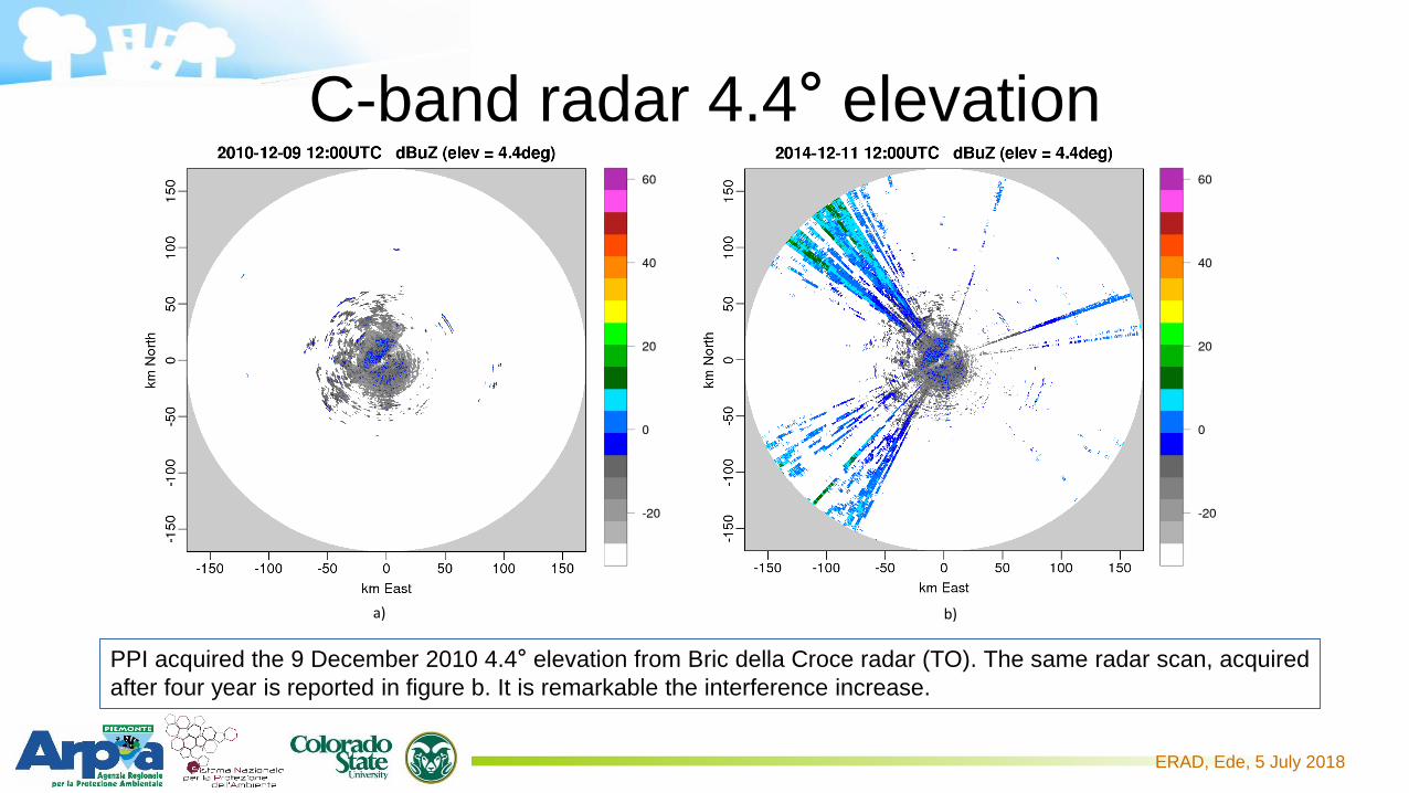
C-band radar 4.4° elevation
a) b)
PPI acquired the 9 December 2010 4.4° elevation from Bric della Croce radar (TO). The same radar scan, acquired
after four year is reported in figure b. It is remarkable the interference increase.

ERAD, Ede, 5 July 2018
C-band RFI Identification
Location of towers transmitting in the C-
band (green points) and Bric della Croce
radar (violet pentagon ).
The figure shows the towers selected by
the interference zones model:
1. Antennas pointing to the radar
2. Tower location is visible from the radar.
Amount of selected towers: 256
Focus on this particular tower.

ERAD, Ede, 5 July 2018
C-band RFI Identification
Bric della Croce radar
WLANExample of tower in
optical visibility with Bric
della Croce radar.
During the 2015 in-field
measurements with the
Italian Ministry of
Economic Development,
comparing the SSID
with the available
information, these
sources were found to
interfere the Bric della
Croce radar.

ERAD, Ede, 5 July 2018
X-band radar
Mobile radar used for research purposes.
Currently located near Vercelli, 60km North-East of Turin
Operational frequency: 9.366GHz
RFIs started from 2014, continuously
increasing.
Day-night pattern: RFIs received from
approximately 6 a.m. to midnight

ERAD, Ede, 5 July 2018
X-band RFI
Maximum of echoes
received during a day (in
colors) overlapped on the
map.
The black dots represents
the Base Station of a
mobile operator
transmitting the LTE
1.8GHz.
The lines represent the ray
between the radar and the
B.S.
Note that the radar range
has been divided by 2.
Z (dBZ)

ERAD, Ede, 5 July 2018
X-band RFI – LTE signal
OFDM based signal. Basic unit in which data are transmitted is the
LTE symbol with QAM, QPSK a CAZAC sequences as possible
modulations. Total duration of the symbol is 71.3μs and 71.9μs for
special symbols.
Down-link of the 1860-1880MHz LTE signal:
1.8732GHz x 5 = 9.366GHz which is the radar operating frequency
Maximum spurious level at X-band: -30dBm ETSI-TS 136 106 V10.0.0
This particular signal is not transmitted from midnight to 6 a.m. in
the radar area.

ERAD, Ede, 5 July 2018
X-band RFI – time series
Scattergram I vs Q for h-pol and v-pol.
Data distributed along a circle.
Is this modulation comparable to LTE symbols?
Iv vs Ih and Qv vs Qh plots. Note that the
data are distributed elliptically along the
-45° slope line. Linearly polarized signal
reflected by the environment surfaces
during its path to the radar.
RFI duration: 71.7 μs

ERAD, Ede, 5 July 2018
X-band RFI – time seriesReference Signals (RS) and Primary
Synchronization Signals (P-SS) may be
constructed from a Constant Amplitude Zero
AutoCorrelation sequence named Zadoff-Chu
sequence
ZC properties:
1. Constant amplitude
2. cyclic auto-correlation of each ZC
sequence results in a single impulse at
time offset zero.
1. RFI amplitude vary less than 5%;
2. RFI H-pol. autocorrelation is a single pulse at time lag zero.

ERAD, Ede, 5 July 2018
DFW X-band radars networkAddison radarCleburne radar

ERAD, Ede, 5 July 2018
DFW X-band radars networkDFW RFIs features:
• Few interferences received per day
• High time and spatial variability
ƒ (MHz)Uplink (MHz)
(Mobile to Base)
Downlink (MHz)
(Base to Mobile)
Europe 1800 1710.2 – 1784.8 1805.2 – 1879.8
North America 1900 1850.2 – 1909.8 1930.2 – 1989.8
What is the RFI source?
No downlink communication allowed in the 1800MHz band.
Uplink of the LTE, user devices low power.
Could telecommunications affect CASA radars as Arpa X-band radar?

ERAD, Ede, 5 July 2018
Conclusions
C-band radar:
• Broadband internet access towers cause
severe interferences
• Time series data show high variability in the
interference duty cycle
• SSID may help to identify the interference
sources using the regional database of
electromagnetic sources
• ITU standards compliance
X-band radar:
• Day-night pattern of the received
interferences
• No in-band transmissions allowed out-of-
band or spurious emissions
• I-Q data analysis show high correlation due
to artificial source. The polarization state
(slant-pol) is widely used in mobile Base
Stations.
• Likely due to 4G mobile communications
• In-field measurement to identify which are
the interfering base stations.First step of the enhanced RFI removal tool

ERAD, Ede, 5 July 2018

ERAD, Ede, 5 July 2018
Bibliography
• Reed, J. H., Clegg, A. W., Padaki, A. V., Yang, T., Nealy, R., Dietrich, C., Mearns, D. M. (2016). On
the co-existence of TD-LTE and radar over 3.5 GHz band: An experimental study. IEEE
Wireless Communications Letters, 5(4), 368-371.
• Joe, P., Scott, J., Sydor, J., Brandão, A., & Yongacoglu, A. (2005, October). Radio Local Area
Network (RLAN) and C-Band Weather Radar Interference Studies. In Proc. 32nd AMS Radar
Conference on Radar Meteorology.
• Lake, J. L., Yeary, M., & Curtis, C. D. (2016, May). Effects of radio frequency interference
mitigation strategies on meteorological data. In Radar Conference (RadarConf), 2016 IEEE
(pp. 1-5). IEEE
• Horváth, Z., & Varga, D. (2009, October). Elimination of RLAN interference on weather radars
by channel allocation in 5 GHz band. In Ultra Modern Telecommunications & Workshops, 2009.
ICUMT'09. International Conference on (pp. 1-6). IEEE.
• Joseph, W., Pareit, D., Vermeeren, G., Naudts, D., Verloock, L., Martens, L., & Moerman, I. (2013).
Determination of the duty cycle of WLAN for realistic radio frequency electromagnetic field
exposure assessment. Progress in Biophysics and Molecular Biology, 111(1), 30-36.

ERAD, Ede, 5 July 2018
Bibliography
• TRISTANT, P. (2009, September). RLAN 5 GHz interference to weather radars in Europe. In
ITU/WMO Seminar on use of radio spectrum for meteorology: Weather, Water and Climate monitoring
and prediction.
• Saltikoff, E., Cho, J. Y., Tristant, P., Huuskonen, A., Allmon, L., Cook, R.,Joe, P. (2016). The threat to
weather radars by wireless technology. Bulletin of the American Meteorological Society, 97(7), 1159-
1167.
• Keranen, R., Rojas, L., Nyberg, P. E. T. R. I. (2013). Progress in mitigation of WLAN interferences at
weather radar. In 36th Conf. on Radar Meteorology.
• LTE: Evolved Universal Terrestrial Radio Access (E-UTRA); User Equipment (UE) radio transmission and
reception ETSI TS 136 101 Technical Specification.
• LTE in a Nutshell: The Physical Layer, 2010, Telesystem Innovations Inc.
• http://webgis.arpa.piemonte.it/campi_elettromagnetici_webapp/
• https://www.ntia.doc.gov/files/ntia/publications/ntia00-40.pdf
Recommended