Week 5: Proportional & G.M. Counters
© DJMorrissey, 2o19
Ion Chambers
Proportional Counters, Ch. 6-- multiplication process-- resolution-- position measurement--- wires--- holes --- plates
Geiger-Mueller Counters, Ch. 7
Principles of Scintillation Counters
Chap. 6 Proportional Counters
© DJMorrissey, 2o19
Consider the drift motion of an ion in a simple ion chamber. The ions will have a thermal velocity plus a component along the field lines. Then after traveling for a mean-free-path they will undergo a collision that will randomize their velocity and they start over. What if the energy gain in one step is greater than the FIP of the buffer gas?
Similar to qualitative Fig. 6.2 Knoll, 3rd ,4th Eds.
mMVmx
FIPq
atmatmxorPammaird
EqxwherexqE
e
MFP
nMFP
MFPeMFPe
/200~106
~
1106/6.6)(21
~~~
8
8
2
-
-=
=
D®DDD
e
l
rpl
lele
(for molecules)
This value is too large for a nominal detector and so no multiplication of/by molecular ions.However, MV/m = keV/mm is achievable over short distances. Recall that the electrons will have much longer mean-free paths –electrons can be multiplied or “avalanched”.

Proportional Counters – Multiplication on Wires
© DJMorrissey, 2o19
Fig. 6.4
Knoll, 3rd,4th Eds.
e(x)
x
d
Parallel plates
€
V x( ) =V0 1−xd
#
$ %
&
' (
+ -
Wire radius “a”Chamber radius “b”
( ) ( )abrVr /ln0=e
Typical Case: wire radius, a = 80 µm @ 2 kV & chamber radius 2cm
( ) ( ) rV
xrVr 360~10.8/02.0ln
20005-=e
~1 MV/m when r = 0.36 mm= 360 µm
Proportional counters are gas filled and generally use wire anodes (recent devices use thin lines or holes on printed circuit boards).
a) b)

Proportional Counters – Townsend Avalanche
© DJMorrissey, 2o19
Start with one electron, each generation follows in proportion to give a distribution governed by the mean-free-path (w/ binary collisions).
Uniform field produces exponential growth, a(E) = a(r) = cons’t:
Non-uniform field requires a transformation a(E) to a(r) using dr/dE:
( )
( )òò =
=«=®+=
-
-
-
----
-
dEdEdrE
ndn
nrnMenrnnr
drdn r
a
a a
00
)()(
α/E
V-1
Townsend coefficients, a, depend on cross sections (mean free paths) and on “w” – thus depend on gas and are strong functions of E.
Additional mechanism of Penning ionization: Ne* + Ar ® Ne + Ar+ + e-
FIP (Ar) = 15.7 < E1 (Ne) = 16.6 FIP (Ne) = 21.5 eV

Proportional Counters – “M”
© DJMorrissey, 2o19
The general form for the multiplication factor, M, can be derived from simple arguments:
Fig. 6.10 Knoll, 3rd Ed.
Fig. 6.11 Knoll, 4th Ed.
( )
( )
( )
textinEqKabpa
VVab
VM
EMthenArNegeEEif
dEE
EM
rErrrE
dEdEdrE
ndn
critr
anoder
8.6.ln)/ln(
ln2ln)/ln(
ln
lnln]01.0..[
1ln
)(/1/1)(
2
úû
ùêë
é-÷÷ø
öççè
æD
=
µ+µ
÷øö
çèæµ
µ®µ
=
ò
òò
-
-
-
-
l
a
a
a
DV is the voltage drop in one MFP, K is the critical E/p for multiplication
For a cylindrical detector:
Diethorn’s equation with two parameters that depend on the gas.

Proportional Counters – Resolution
© DJMorrissey, 2o19
If the electrons don’t have a history (reset at each mean-free path) then each ionization event is independent. The probability of such independent events follows the Furry Distribution of “A-sized” avalanches with average A = M (essentially a power-law):
0
0.005
0.01
0.015
0.02
0.025
0.03
0.035
0.04
0.045
0 20 40 60 80 100A
P(A)
<A>=25<A>=50<A>=75<A>=10022
1
)(
11)( A
AeAP
AAAP A
AA
Flury
A
Flury =»®÷øö
çèæ -
=-
-
s
The resolution of the total charge, Q, will have two contributions: variation of the primary charge production and the multiplication
÷÷ø
öççè
æ+÷÷ø
öççè
æ=÷÷
ø
öççè
æ
÷øö
çèæ+÷÷
ø
öççè
æ=÷÷
ø
öççè
æ
=÷øö
çèæ+÷÷
ø
öççè
æ+÷÷
ø
öççè
æ=÷÷
ø
öççè
æ
=
IPIP
Q
M
IP
Q
IPNM
e
qe
IP
NQ
eIP
NNF
Q
MNF
Q
NFbutMqNQ
MqNQ
12
22
22222
s
ss
sssss
( )úúû
ù
êêë
é+÷
øö
çèæ
¶¶
=®++=º= å=
.../...1 22
1221
11A
IPM
IPIP
N
ii
IP ANA
NA
NAA
NAM
IP
ss
2222
2
2
2
222222
2
1
1121
AA
IP
M
AAAA
IPiA
IPM
AMbutMNM
butNN i
sss
ssssss
===
===÷÷ø
öççè
æ= å !
The text argues that (sA / A)2 is < 1 … perhaps ½ .
0
Proportional Counters – some difficulties
© DJMorrissey, 2o19
Approximately ½ of the charge is created ~ lMFP from the anode. The motion of the cations away from the anode induces the signal.
Fast rising signal; HV is shielded, slow cations have a long way to move to be neutralized on cathode. [ use grids ]
Multiplication process produces much more radiation damage to filling gas than primary ionization – no problem for noble gases (see below) but can damage anode itself.
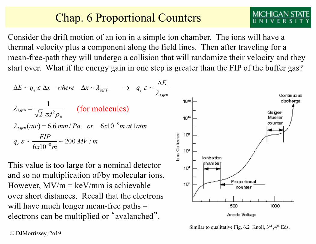
Gas mixtures? The number of atoms in excited states will grow in proportion to the multiplication. The excited states tend to decay by photon emission rather than by Penning ionization in pure gases – the photons are often UV and strike the cathode (wall). Being a metal, the cathode will tend to emit a photoelectron … similarly the collision of an atomic ion with the cathode during the neutralization can release an electron.
“Quench gas”: Mix in a small amount of a small molecule – molecules have vibrational modes that can absorb energy and they tend not to radiate UV photons (IR more likely). Also these molecules will tend to collect the charge due to charge-exchange reactions and are less likely to emit electrons from the cathode on neutralization. However, these molecules tend to get damaged – need to flow the gas. Most used mixture: “P-10” 90% Ar 10% methane
T.L. van Vuure, Ph.D, TU-Delft, 2004
Beware of Cartoon !
65
0E+0
1E-9
2E-9
200 300 400 500 600 700 800 900
Wavelength (nm)
Arb
. u
nits
He+40%CF4-1bar
Ar+5%CF4-1bar
Xe+5%TMA-1bar
figure 46 Optical spectrum of the light emissions that occur during operation of the GEM in
three gas mixtures.
An emission spectrum was measured by stepping the monochromator at 2 nm
intervals through the wavelength range. In figure 46 the spectra for the examined gas
mixtures are shown, all with the detector operating at a charge gain of 100.
Unfortunately the light yield at different wavelengths cannot be compared, because
the spectra have not been corrected for the transmission of the monochromator and the
quantum efficiency of the photomultiplier.
3.5 Conclusions The following conclusions can be drawn from the research performed in section 3.
When comparing different GEM geometries with each other, no hole size can be
shown to hold a substantial advantage over another. In some counting gases a hole
size of 80 µm leads to a higher gain than a hole size of 60 µm, but it can also be the
other way around. The typical difference is less than a factor ~2.
Of the utmost importance in GEM geometry is the ratio between hole size and pitch.
This directly influences electron transparency and yield. For example, the examined
GEM60/140 requires a very low drift field compared to GEM80/140 and GEM60/90
in order to reach the same effective gain. As discussed in section 2.3.4, the effective
gain is the product of the real gas gain, electron transparency and electron yield. For
this reason, the effective gain in the GEM60/140 is significantly reduced because of
the lower values for transparency and yield.
For GEM60/90 and GEM80/140 convenient working values for drift and induction
field are 1 and 4 kV/cm. For the drift field, this can be shown to be on the plateau for

Proportional Counters – Multiwires & Position
© DJMorrissey, 2o19
Field lines are approximately perpendicular to wire plane at large distances –electrons drift towards plane and retain position information. Many “wire chambers” have been developed to measure the positions of various particles.
Figs. 6.19 & 20 Knoll, 3rd Ed.
Figs. 6.21 & 22 Knoll, 4th Ed.Read primary signal on wires, induced signals on cathode strips top and bottom – calculate 2D position.
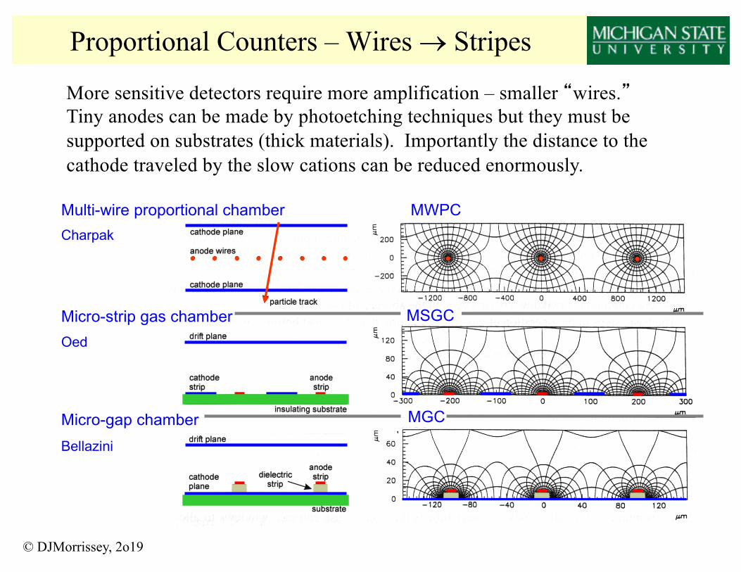
Proportional Counters – Wires ® Stripes
© DJMorrissey, 2o19
Multi-wire proportional chamber MWPCCharpak
Micro-strip gas chamberOed
•••••••• • • •
Micro-gap chamberBellazini
MGC
MSGC
More sensitive detectors require more amplification – smaller “wires.”Tiny anodes can be made by photoetching techniques but they must be supported on substrates (thick materials). Importantly the distance to the cathode traveled by the slow cations can be reduced enormously.

Proportional Counters – Wires ® Stripes, Nope!
Thin metal strips on insulating support, generally resistive glass, have a very high rate capability due to high fields and short distance of travel for the cations.
However, strips are permanently damaged by sparks or other discharges which kills the detector.
© DJMorrissey, 2o19

Amos Breskin
MICROMEGAS MICROMEGAS MICROMEGAS
MICROMEGAS 1996Narrow gap (50Narrow gap (50--100 100 µµm) parallelm) parallel--plate multiplier with thin cathode mesh & Insulating pillarsplate multiplier with thin cathode mesh & Insulating pillars
Y. Y. GiomatarisGiomataris et al, et al, NuclNucl. . InstrInstr. and . and MethMeth. A376(1996)239. A376(1996)239
1996
FAST, HIGH RATES, HIGH SPATIAL RESOLUTIONNEW TECHNIQUES FOR MASS PRODUCTION
BUT: only single-stage � sometimes gain limits
Proportional Counters – Micro Frisch GridMicroMeGas detectors are made on a tiny scale with micro fabrication techniques. These devices have high spatial resolution but may be gain limited because they are only one-stage by definition. Also they can be integrated with electronics, but they are generally small.
Y. Giomataris, et al. NIM A376 (1996) 29
14x14 mm2 , 256x256 pixels, 55x55 µm2
H. Van der Graaf, IEEE-NSS workshop, 2007© DJMorrissey, 2o19

Proportional Counters – MicroMeGas – AT-TPC
D. Suzuki et al., Nucl. Instrum. Meth. A 660 (2011) 64. D. Suzuki et al., Nucl. Instrum. Meth. A 691 (2012) 39–54D.Suzuki et al., Phys. Rev. C 87 (2013) 054301
© DJMorrissey, 2o19
•1m length, 50cm diameter gas volume•Electrons amplified using a Micromegas with 10,240 triangular pads •Embeded in a 2T magnetic field for B-rho analysis (tracks curve …)
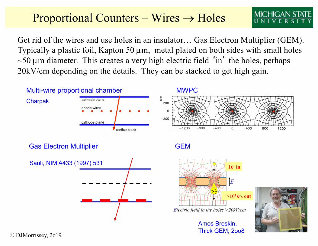
Proportional Counters – Wires ® Holes
© DJMorrissey, 2o19
Multi-wire proportional chamber MWPCCharpak
•••••••• • • •
Get rid of the wires and use holes in an insulator… Gas Electron Multiplier (GEM). Typically a plastic foil, Kapton 50 µm, metal plated on both sides with small holes ~50 µm diameter. This creates a very high electric field ‘in’ the holes, perhaps 20kV/cm depending on the details. They can be stacked to get high gain.
Sauli, NIM A433 (1997) 531
Gas Electron Multiplier GEM
Amos Breskin, Thick GEM, 2oo8

Proportional Counters – PPAC
© DJMorrissey, 2o19
Transmission detectors in the path of the beam should be highly uniform. Opinion: The MWPC devices are not suitable for radioactive ion beams … parallel-plate avalanche counters
Pressure foilX-cathodeAnodeY-cathodePressure foil
NSCL PPAC, NIM A 348 (1994)314
V0 ~ 500 V, p = 5 torr,~ 3mm gap anode-cathode
atmmMV
torratmtorr
mV
p20
5/760
003.0500
==e
QTotal
R1 R2¬Q1 Q2 ®
Resistive charge division
Cathode foil with stripesResistor chain on pcbInduced charge is divided in two.
¬Q
1Q
2 ®

Chap. 7 Geiger-Mueller Counters
© DJMorrissey, 2o19
Increase field in Proportional counter so that the avalanche spreads along the entire length of the wire … this will produce the largest signal but a sheath of cations will terminate the applied field.Rutherford & Geiger, 1908
Beware of cartoon !
Hans Geiger (1882-1945) was a German physicist who introduced the first reliable detector for alpha particles and other ionizing radiation.His basic design is still used, although more advanced detectors also exist. His first particle counter was used in experiments that identified alpha particles as being the same as the nucleus of a Helium atom.He accepted his first teaching position in 1925 at the University of Kiel, where he worked with Walther Müller to improve the sensitivity and performance of his particle counter.
Recombination at the wall leads to “after pulse”He+ + e- (wall) ® He* ® He + hn (UV)
He+ + M ® He + M+
M+ + e- (wall) ® M* ® M + hn (IR)GM tubes are sealed … “M” gets burned up.

Geiger-Mueller Counter Example
© DJMorrissey, 2o19
Typical device: 1 atm P-10 gas (90%Ar, 10%CH4) Anode: ra ~ 30 µm; Cathode rb ~ 1 cm; 10 cm long
M~106 gives VR ~ 1 V – Estimate V0 , t, C & R
+V0Rbias
R
( )
W=®
=>
=÷÷ø
öççè
æ=÷÷
ø
öççè
æ=
-==>
®=
+D=
=D-=÷÷ø
öççè
æ÷÷ø
öççè
æD
=
-
-
-+
-++
614
6
24
60
000
00
400
10.690108.410.33~33~
33/300
01.0
/30031013
3~10.305.77
)/ln(~)(
450~5.2740ln
)/ln(ln2lnln)/ln(ln
1.66.23,/108.4)/ln(
ln2ln)/ln(
ln
xFx
xRsRC
ssmm
smatmmMV
sVatmmx
atmmMVv
atmmMV
xabprV
prE
pEv
vr
VVVV
KabpaVMabVV
TableinVVatmcmVxKKabpa
VVab
VM
ab
µ
µt
µ
µt
l
ll
( )
FxCx
mxmNcoulxC
dAC
rrlC
ab
14
5
2212
00
108.4)103/01.0ln(
1.0//10854.8/ln
-
-
-
=
=
==
p
epeCylinder Parallel Plates
Recommended