SANDIA REPORT SAND2011-1094 Unlimited Release Printed February 2011
Wind Turbine Composite Blade Manufacturing: The Need for Understanding Defect Origins, Prevalence, Implications and Reliability Douglas S. Cairns Trey Riddle Jared Nelson Prepared by Sandia National Laboratories Albuquerque, New Mexico 87185 and Livermore, California 94550
Sandia National Laboratories is a multi-program laboratory managed and operated by Sandia Corporation, a wholly owned subsidiary of Lockheed Martin Corporation, for the U.S. Department of Energy’s National Nuclear Security Administration under contract DE-AC04-94AL85000.
Approved for public release; further dissemination unlimited.
2
Issued by Sandia National Laboratories, operated for the United States Department of Energy by Sandia Corporation. NOTICE: This report was prepared as an account of work sponsored by an agency of the United States Government. Neither the United States Government, nor any agency thereof, nor any of their employees, nor any of their contractors, subcontractors, or their employees, make any warranty, express or implied, or assume any legal liability or responsibility for the accuracy, completeness, or usefulness of any information, apparatus, product, or process disclosed, or represent that its use would not infringe privately owned rights. Reference herein to any specific commercial product, process, or service by trade name, trademark, manufacturer, or otherwise, does not necessarily constitute or imply its endorsement, recommendation, or favoring by the United States Government, any agency thereof, or any of their contractors or subcontractors. The views and opinions expressed herein do not necessarily state or reflect those of the United States Government, any agency thereof, or any of their contractors. Printed in the United States of America. This report has been reproduced directly from the best available copy. Available to DOE and DOE contractors from U.S. Department of Energy Office of Scientific and Technical Information P.O. Box 62 Oak Ridge, TN 37831 Telephone: (865) 576‐8401 Facsimile: (865) 576‐5728 E‐Mail: [email protected] Online ordering: http://www.osti.gov/bridge Available to the public from U.S. Department of Commerce National Technical Information Service 5285 Port Royal Rd. Springfield, VA 22161 Telephone: (800) 553‐6847 Facsimile: (703) 605‐6900 E‐Mail: [email protected] Online order: http://www.ntis.gov/help/ordermethods.asp?loc=7‐4‐0#online
3
SAND2011‐1094
Unlimited Release
Printed March 2011
Wind Turbine Composite Blade Manufacturing: The Need for Understanding Defect Origins, Prevalence, Implications and Reliability
Douglas S. Cairns
Principal Investigator and Lysle A. Wood Distinguished Professor
Jared Nelson and Trey Riddle Ph.D. Candidates
Department of Mechanical and Industrial Engineering
Montana State University Bozeman, MT
ABSTRACT Renewable energy is an important element in the US strategy for mitigating our dependence on non‐domestic oil. Wind energy has emerged as a viable and commercially successful renewable energy source. This is the impetus for the 20% wind energy by 2030 initiative in the US. Furthermore, wind energy is important on to enable a global economy. This is the impetus for such rapid, recent growth. Wind turbine blades are a major structural element of a wind turbine blade. Wind turbine blades have near aerospace quality demands at commodity prices; often two orders of magnitude less cost than a comparable aerospace structure. Blade failures are currently as the second most critical concern for wind turbine reliability. Early blade failures typically occur at manufacturing defects. There is a need to understand how to quantify, disposition, and mitigate manufacturing defects to protect the current wind turbine fleet, and for the future. This report is an overview of the needs, approaches, and strategies for addressing the effect of defects in wind turbine blades. The overall goal is to provide the wind turbine industry with a hierarchical procedure for addressing blade manufacturing defects relative to wind turbine reliability. Keywords: Wind Turbine Blade, Composites, Manufacturing, Defects, Damage Tolerance, Reliability

4
I. INTRODUCTION
The buzz of renewable energy has been on the rise in recent years after its decline in the early 1980s as
a consequence of the reduction of oil prices after the oil crisis of the 1970s. While the idea has captured
the hearts and imaginations of the people, most of these technologies have yet to deliver the bottom
line; profits for share holders. Wind energy is perhaps the only exception to this rule as evident by
Figure 1. It can be seen in this figure that Wind Energy dwarfs all other renewable energy sources for
new installed capacity and competes directly with non‐renewable energy sources (1).
Figure 1: Percentage of New Power Generation Capacity (1).
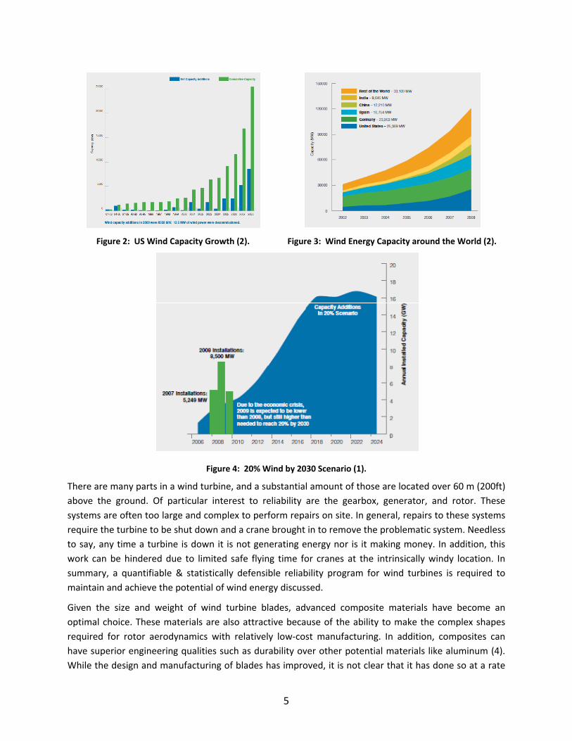
The capacity of Wind Energy installed in the United States has been growing steadily since the late 1990s
approaching a 50% increase in recent years as seen in Figure 2 (1). This increase can be attributed to the
fact that wind energy is financially feasible which in turn has made it the flagship for renewable energy
around the world (Figure 3).
US Department of Energy is showing its support for wind energy by implementing a policy that would
achieve 20% wind energy by 2030 (3). Wind power generation must continue close to current rates in
order to achieve this goal (Figure 4). While the economics are profitable for investors, the growth and
wane of installations is consistent with the introduction and removal of subsidies. Wind energy, as all
business, is continually looking to improve the profit margins. Top tier locations for farms are running
thin. Couple this with the natural intermittency of wind and the economics begin to deteriorate. It is
important that wind farms achieve maximum availability by reducing down time due to maintenance
and failures as much as possible.
5
Figure 2: US Wind Capacity Growth (2).
Figure 3: Wind Energy Capacity around the World (2).
Figure 4: 20% Wind by 2030 Scenario (1).
There are many parts in a wind turbine, and a substantial amount of those are located over 60 m (200ft)
above the ground. Of particular interest to reliability are the gearbox, generator, and rotor. These
systems are often too large and complex to perform repairs on site. In general, repairs to these systems
require the turbine to be shut down and a crane brought in to remove the problematic system. Needless
to say, any time a turbine is down it is not generating energy nor is it making money. In addition, this
work can be hindered due to limited safe flying time for cranes at the intrinsically windy location. In
summary, a quantifiable & statistically defensible reliability program for wind turbines is required to
maintain and achieve the potential of wind energy discussed.
Given the size and weight of wind turbine blades, advanced composite materials have become an
optimal choice. These materials are also attractive because of the ability to make the complex shapes
required for rotor aerodynamics with relatively low‐cost manufacturing. In addition, composites can
have superior engineering qualities such as durability over other potential materials like aluminum (4).
While the design and manufacturing of blades has improved, it is not clear that it has done so at a rate
6
necessary to ensure a 20 year design life. Many of the blade suppliers are using technologies and
techniques that were developed for structures with much lower design loads and criteria. While these
methods are inexpensive, they are thought to offer questionable reliability.
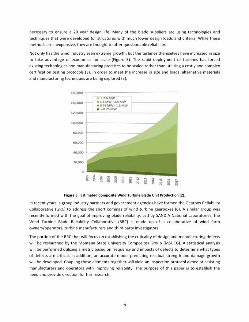
Not only has the wind industry seen extreme growth, but the turbines themselves have increased in size
to take advantage of economies for scale (Figure 5). The rapid deployment of turbines has forced
existing technologies and manufacturing practices to be scaled rather than utilizing a costly and complex
certification testing protocols (3). In order to meet the increase in size and loads, alternative materials
and manufacturing techniques are being explored (5).
Figure 5: Estimated Composite Wind Turbine Blade Unit Production (2).
In recent years, a group industry partners and government agencies have formed the Gearbox Reliability
Collaborative (GRC) to address the short comings of wind turbine gearboxes (6). A similar group was
recently formed with the goal of improving blade reliability. Led by SANDIA National Laboratories, the
Wind Turbine Blade Reliability Collaborative (BRC) is made up of a collaborative of wind farm
owners/operators, turbine manufacturers and third party investigators.
The portion of the BRC that will focus on establishing the criticality of design and manufacturing defects
will be researched by the Montana State University Composites Group (MSUCG). A statistical analysis
will be performed utilizing a metric based on frequency and impacts of defects to determine what types
of defects are critical. In addition, an accurate model predicting residual strength and damage growth
will be developed. Coupling these elements together will yield an inspection protocol aimed at assisting
manufacturers and operators with improving reliability. The purpose of this paper is to establish the
need and provide direction for this research.
7
II. BACKGROUND, SCIENTIFIC MERIT AND RATIONALE
Improving reliability of wind turbine blades is the primary goal of the BRC. In order to do this, a
comprehensive understanding of the causes of blade failures is necessary. Classification of known defect
types and establishing a criticality metric will lead to probabilistic and damage tolerance methodologies.
These types of techniques have been successfully utilized to improve airline safety for decades.
Implementing this information at the manufacturing level will establish quality guidelines while reducing
tower down‐time, rework, scrap‐rates, and ensuring a successful life‐cycle. In general, composites
researchers have made significant headway into determining the effects of defects and utilizing non‐
destructive evaluation. However, a bridge is necessary to correlate this generalized information to the
specific uses of composites for wind energy.
A. Reliability Issues
Reliability is an inherent characteristic of a system, therefore it should be considered a design parameter
and its assessment should be performed as an integral part of the design process. In many low cost
composite manufacturing instances reliability is performed as a subjective and qualitative step rather
than incorporating a quantifiable reliability metric. In order to achieve a truly reliable system,
quantitative terms must be allied. For simplicity, the reliability of a wind turbine can be divided into two
components; design/manufacturing and in‐life evaluation. The first step in developing improved
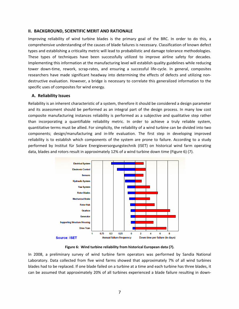
reliability is to establish which components of the system are prone to failure. According to a study
performed by Institut für Solare Energieversorgungstechnik (ISET) on historical wind farm operating
data, blades and rotors result in approximately 12% of a wind turbine down time (Figure 6) (7).
Figure 6: Wind turbine reliability from historical European data (7).
In 2008, a preliminary survey of wind turbine farm operators was performed by Sandia National
Laboratory. Data collected from five wind farms showed that approximately 7% of all wind turbines
blades had to be replaced. If one blade failed on a turbine at a time and each turbine has three blades, it
can be assumed that approximately 20% of all turbines experienced a blade failure resulting in down‐
8
time. The operators reported that the leading causes of failure where manufacturing defects and
lighting strikes (7). However, based on discussions with a number of major wind turbine OEMs and blade
manufactures this number is probably higher (8).
Manufacturing quality is a critical issue for improved reliability. As recently as February 2010 Suzlon
Energy Ltd., the world’s fifth leading wind turbine manufacturer, announced a retrofit program to
resolve blade cracking issues discovered during the operations of some of its S88 turbines in the United
States. The six‐month retrofit program will be carried out by maintaining a rolling stock of temporary
replacement blades to minimize the downtime for operational turbines. The cost of the retrofit program
is estimated to be $25 million (9). Problems such as these are not exclusive to the wind energy industry.
Growing use of composites in the aerospace industry, for example, has led to similar problems. In
August of 2009 a Boeing supplier halted manufacturing the barreled pieces of the 787's mid‐section
because of a problem in the manufacturing process. This manufacturing problem resulted in microscopic
wrinkles in structural stringer supports along the length of the airframe. Boeing had to develop a patch
in order to repair the existing plane sections. Subsequently newer sections will be made utilizing a
different manufacturing process (10).
Large blades are likely to use the heaviest possible reinforcing fabrics or prepreg ply thickness to achieve
manufacturing efficiency. Increases in fabric weight—and therefore thickness—may affect basic in‐plane
properties, delamination, and problems associated with ply drops where the thickness is tapered as
confirmed by previous MSUCG research (11). Moreover, thick composite laminates have an increased
likelihood of hidden flaws and multiple flaws being grouped in the same local area. A number of
production‐related flaws may occur in larger structures which are more easily avoided in smaller
structures, and rarely appear in test coupons. Typical of these are fabric joints and overlaps where
individual rolls of fabric terminate, and flaws in fabric where individual strands terminate during
production of the fabric. Other factors which are more likely in larger blades include fiber waviness,
large scale porosity, large resin rich areas, and resin cure variations through the thickness (5).
It has been suggested that a flaw in a 50 meter structure is just as harmful as a flaw in a 5 meter
structure (12). Moreover, utilizing a Weibull Distribution to compare the strength of a large structure to
the strength of a small structure shows that larger structures have a greater probability of a critical flaw.
This conclusion is valid when the distribution has the form (Vlarge/Vsmall)1/m, where V is the volume and m
is the Weibull parameter (13).
B. Aerospace and Aviation Analogs
i. General Discussion on Aviation Safety Compliance
There is a notable difference between military and civil aviation methods of compliance. For military
aircraft, the government defines the requirements with Military Specifications and works with the
manufacturer to establish the method of compliance. In civil aviation, the government defines the
requirements through regulations (FAR’s, JAR’s) and accepted means of compliance through Advisory
Circulars. Compliance must be demonstrated to the agency (FAA, JAA) and in this instance the
government is a neutral third party.
9
The Federal Aviation Administration (FAA) regulates the safety concerns for the civil aviation industry.
Their regulations stretch into the manufacturing and inspection protocols. Federal Aviation Regulation
(FAR) 25.571 Damage Tolerance & Fatigue Evaluation of Structure states that “An evaluation of the
strength, detail design, and fabrication must show that catastrophic failure due to fatigue, corrosion,
manufacturing defects, or accidental damage will be avoided through the operational life of the
airplane” (7).
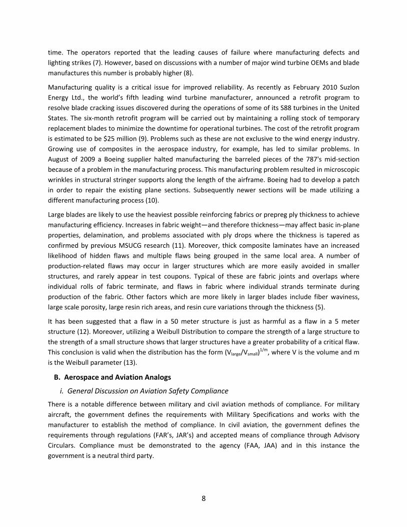
Advisory Circular (AC) 20‐107B on Composite Aircraft Structure describes an acceptable means of
showing compliance with the provisions of FAR 25.571 for the special case of aircraft structures
involving fiber reinforced materials. Guidance information is also presented on design, manufacturing,
inspection and maintenance aspects (14). This process can be seen visually in Figure 7. Unfortunately,
there are no such regulations in the wind industry because failures in composite wind turbine blades are
largely an economic problem, not a safety problem (15). However, the economic impact of failures could
significantly affect the growth scenarios presented in Figure 1 through Figure 5 above.
Figure 7: Flow Chart of FAA Safety Program (16).
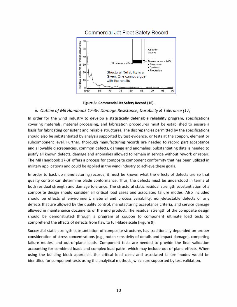
Since the introduction of structural reliability programs in the aviation industry, the safety record has
been greatly improved as seen in Figure 8. The technological corollaries between the aviation industry
and the wind industry would suggest that similar improvements could be attained by the wind industry.
However, the major challenge is to determine the cost/benefit parameter which will achieve the best
economic payoff for improved reliability.
10
Figure 8: Commercial Jet Safety Record (16).
ii. Outline of Mil Handbook 17‐3F: Damage Resistance, Durability & Tolerance (17)
In order for the wind industry to develop a statistically defensible reliability program, specifications
covering materials, material processing, and fabrication procedures must be established to ensure a
basis for fabricating consistent and reliable structures. The discrepancies permitted by the specifications
should also be substantiated by analysis supported by test evidence, or tests at the coupon, element or
subcomponent level. Further, thorough manufacturing records are needed to record part acceptance
and allowable discrepancies, common defects, damage and anomalies. Substantiating data is needed to
justify all known defects, damage and anomalies allowed to remain in service without rework or repair.
The Mil Handbook 17‐3F offers a process for composite component conformity that has been utilized in
military applications and could be applied in the wind industry to achieve these goals.
In order to back up manufacturing records, it must be known what the effects of defects are so that
quality control can determine blade conformance. Thus, the defects must be understood in terms of
both residual strength and damage tolerance. The structural static residual strength substantiation of a
composite design should consider all critical load cases and associated failure modes. Also included
should be effects of environment, material and process variability, non‐detectable defects or any
defects that are allowed by the quality control, manufacturing acceptance criteria, and service damage
allowed in maintenance documents of the end product. The residual strength of the composite design
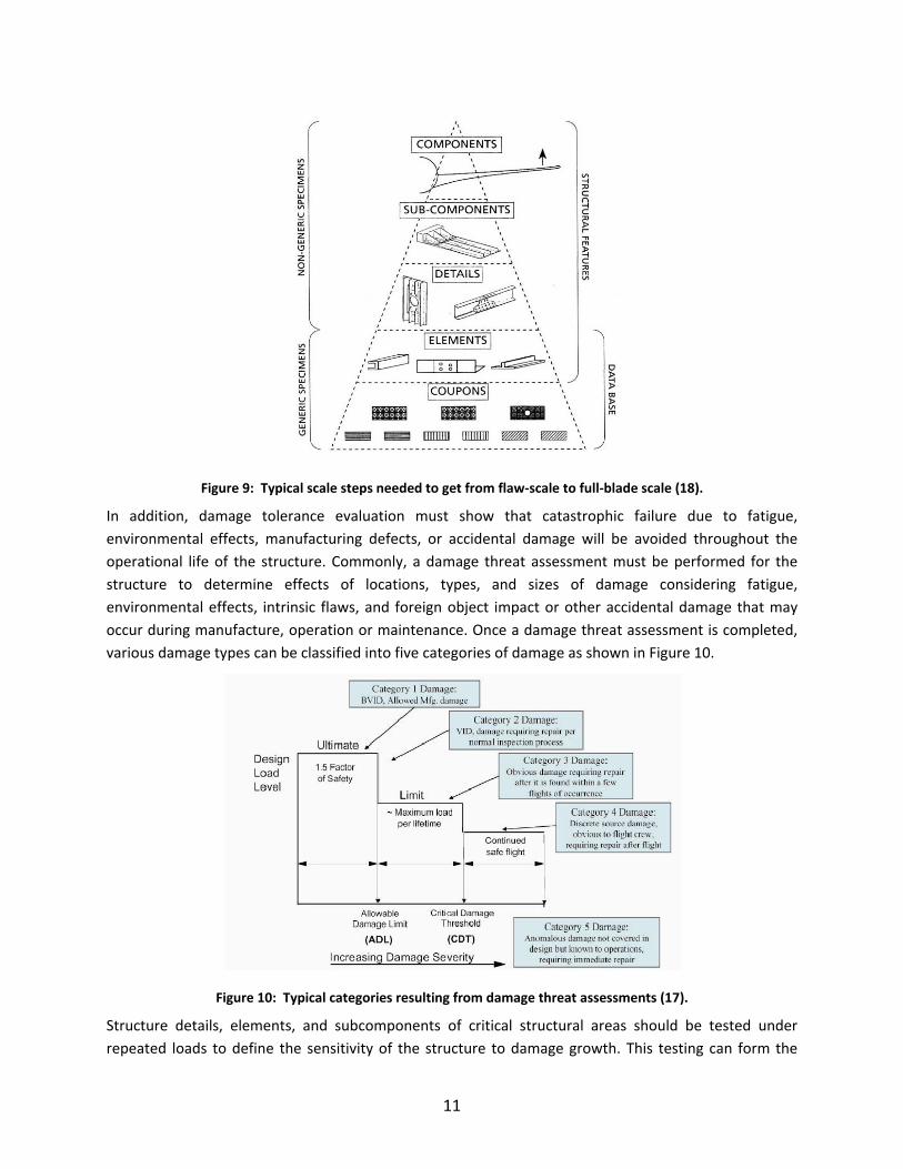
should be demonstrated through a program of coupon to component ultimate load tests to
comprehend the effects of defects from flaw to full‐blade scale (Figure 9).
Successful static strength substantiation of composite structures has traditionally depended on proper
consideration of stress concentrations (e.g., notch sensitivity of details and impact damage), competing
failure modes, and out‐of‐plane loads. Component tests are needed to provide the final validation
accounting for combined loads and complex load paths, which may include out‐of‐plane effects. When
using the building block approach, the critical load cases and associated failure modes would be
identified for component tests using the analytical methods, which are supported by test validation.
11
Figure 9: Typical scale steps needed to get from flaw‐scale to full‐blade scale (18).
In addition, damage tolerance evaluation must show that catastrophic failure due to fatigue,
environmental effects, manufacturing defects, or accidental damage will be avoided throughout the
operational life of the structure. Commonly, a damage threat assessment must be performed for the
structure to determine effects of locations, types, and sizes of damage considering fatigue,
environmental effects, intrinsic flaws, and foreign object impact or other accidental damage that may
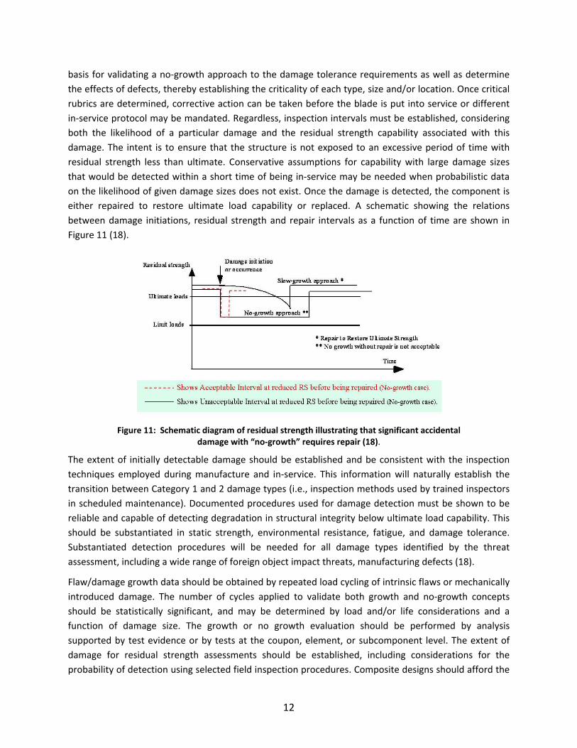
occur during manufacture, operation or maintenance. Once a damage threat assessment is completed,
various damage types can be classified into five categories of damage as shown in Figure 10.
Figure 10: Typical categories resulting from damage threat assessments (17).
Structure details, elements, and subcomponents of critical structural areas should be tested under
repeated loads to define the sensitivity of the structure to damage growth. This testing can form the
12
basis for validating a no‐growth approach to the damage tolerance requirements as well as determine
the effects of defects, thereby establishing the criticality of each type, size and/or location. Once critical
rubrics are determined, corrective action can be taken before the blade is put into service or different
in‐service protocol may be mandated. Regardless, inspection intervals must be established, considering
both the likelihood of a particular damage and the residual strength capability associated with this
damage. The intent is to ensure that the structure is not exposed to an excessive period of time with
residual strength less than ultimate. Conservative assumptions for capability with large damage sizes
that would be detected within a short time of being in‐service may be needed when probabilistic data
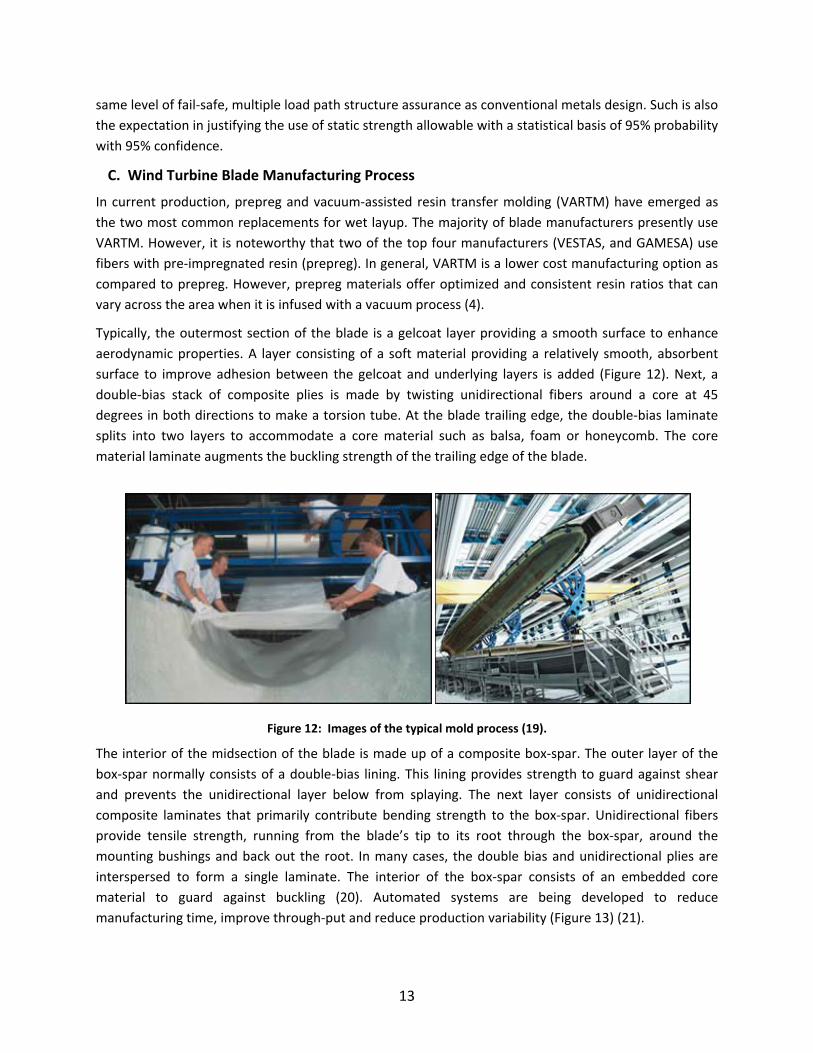
on the likelihood of given damage sizes does not exist. Once the damage is detected, the component is
either repaired to restore ultimate load capability or replaced. A schematic showing the relations
between damage initiations, residual strength and repair intervals as a function of time are shown in
Figure 11 (18).
Figure 11: Schematic diagram of residual strength illustrating that significant accidental damage with “no‐growth” requires repair (18).
The extent of initially detectable damage should be established and be consistent with the inspection
techniques employed during manufacture and in‐service. This information will naturally establish the
transition between Category 1 and 2 damage types (i.e., inspection methods used by trained inspectors
in scheduled maintenance). Documented procedures used for damage detection must be shown to be
reliable and capable of detecting degradation in structural integrity below ultimate load capability. This
should be substantiated in static strength, environmental resistance, fatigue, and damage tolerance.
Substantiated detection procedures will be needed for all damage types identified by the threat
assessment, including a wide range of foreign object impact threats, manufacturing defects (18).
Flaw/damage growth data should be obtained by repeated load cycling of intrinsic flaws or mechanically
introduced damage. The number of cycles applied to validate both growth and no‐growth concepts
should be statistically significant, and may be determined by load and/or life considerations and a
function of damage size. The growth or no growth evaluation should be performed by analysis
supported by test evidence or by tests at the coupon, element, or subcomponent level. The extent of
damage for residual strength assessments should be established, including considerations for the
probability of detection using selected field inspection procedures. Composite designs should afford the
13
same level of fail‐safe, multiple load path structure assurance as conventional metals design. Such is also
the expectation in justifying the use of static strength allowable with a statistical basis of 95% probability
with 95% confidence.
C. Wind Turbine Blade Manufacturing Process
In current production, prepreg and vacuum‐assisted resin transfer molding (VARTM) have emerged as
the two most common replacements for wet layup. The majority of blade manufacturers presently use
VARTM. However, it is noteworthy that two of the top four manufacturers (VESTAS, and GAMESA) use
fibers with pre‐impregnated resin (prepreg). In general, VARTM is a lower cost manufacturing option as
compared to prepreg. However, prepreg materials offer optimized and consistent resin ratios that can
vary across the area when it is infused with a vacuum process (4).
Typically, the outermost section of the blade is a gelcoat layer providing a smooth surface to enhance
aerodynamic properties. A layer consisting of a soft material providing a relatively smooth, absorbent
surface to improve adhesion between the gelcoat and underlying layers is added (Figure 12). Next, a
double‐bias stack of composite plies is made by twisting unidirectional fibers around a core at 45
degrees in both directions to make a torsion tube. At the blade trailing edge, the double‐bias laminate
splits into two layers to accommodate a core material such as balsa, foam or honeycomb. The core
material laminate augments the buckling strength of the trailing edge of the blade.
Figure 12: Images of the typical mold process (19).
The interior of the midsection of the blade is made up of a composite box‐spar. The outer layer of the
box‐spar normally consists of a double‐bias lining. This lining provides strength to guard against shear
and prevents the unidirectional layer below from splaying. The next layer consists of unidirectional
composite laminates that primarily contribute bending strength to the box‐spar. Unidirectional fibers
provide tensile strength, running from the blade’s tip to its root through the box‐spar, around the
mounting bushings and back out the root. In many cases, the double bias and unidirectional plies are
interspersed to form a single laminate. The interior of the box‐spar consists of an embedded core
material to guard against buckling (20). Automated systems are being developed to reduce
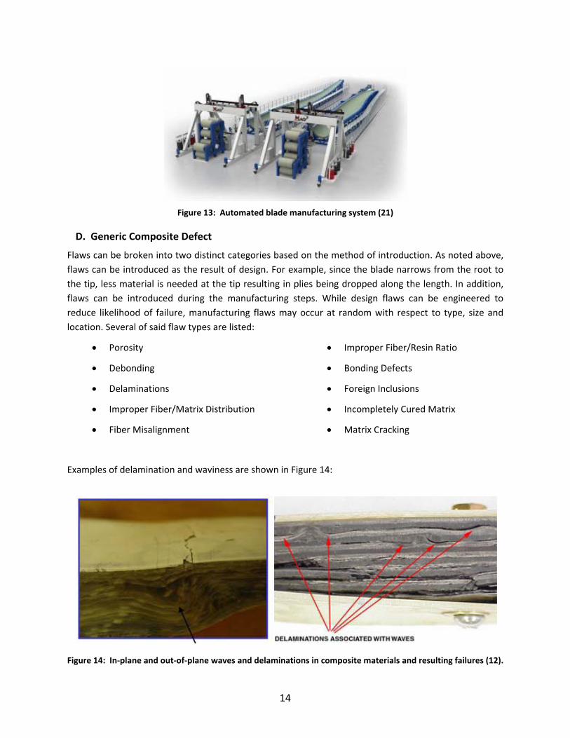
manufacturing time, improve through‐put and reduce production variability (Figure 13) (21).
14
Figure 13: Automated blade manufacturing system (21)
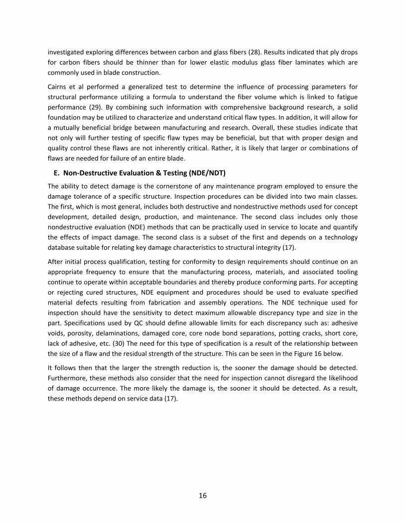
D. Generic Composite Defect
Flaws can be broken into two distinct categories based on the method of introduction. As noted above,
flaws can be introduced as the result of design. For example, since the blade narrows from the root to
the tip, less material is needed at the tip resulting in plies being dropped along the length. In addition,
flaws can be introduced during the manufacturing steps. While design flaws can be engineered to
reduce likelihood of failure, manufacturing flaws may occur at random with respect to type, size and
location. Several of said flaw types are listed:
Porosity
Debonding
Delaminations
Improper Fiber/Matrix Distribution
Fiber Misalignment
Improper Fiber/Resin Ratio
Bonding Defects
Foreign Inclusions
Incompletely Cured Matrix
Matrix Cracking
Examples of delamination and waviness are shown in Figure 14:
Figure 14: In‐plane and out‐of‐plane waves and delaminations in composite materials and resulting failures (12).

15
These types of flaws can lead to extremely disastrous outcomes as shown in Figure 15, which shows the
catastrophic failure of a wind turbine. This situation was the result of a blade failure that was
attributable to a manufacturing defect.
Figure 15: Catastrophic wind turbine failure (12).
Significant research of composite manufacturing and design flaws has been performed by the MSUCG
and others. The MSUCG has contributed by establishing a Composite Materials Fatigue Database that
has tested over 4500 coupons for over 130 material systems (22). This database can be extremely useful
as most of the material systems and defect types tested are those utilized and found in composite
blades. An incomprehensive and brief overview of several studies relating to the flaws noted above
follows.
In‐plane waviness is a common manufacturing flaw (Figure 14) and has been investigated under
compressive loading. Waves up to 1.5 layer thicknesses were tested and it was found that more severe
wave geometries produced reductions in static strength up to 36% even though no wave accounted for
20% of load capacity (23). Bogetti et al found that ply waviness resulted in significant stiffness and
strength reductions only in the 0 deg attributable to out‐of‐plane waviness (24). In addition, their results
indicated that waviness induced interlaminar shear stress and that a plateau region exists below critical
amplitude.
Avery et al utilized the known sensitivity of compressive strength related to fiber straightness to study
structural details such as ply drops and ply joints (25). By varying parameters such as ply thickness,
fraction of ply drops, location, gap and mold geometry and pressure, it was found that ply drops and
joints can provide adequate compressive strength. However, severe knockdowns occurred where large
fiber misalignments were induced. Cairns et al built upon this research by determining that suppressing
damage and delamination in‐service emanating from ply drops is not possible, though in most cases
there is a threshold loading under which little growth after initiation was noted (26). Based on these
results, rules were established for ply drops.
Similarly, delamination between plies is a common cause of failure of composite structures. Mandell et
al established fracture mechanics based methodologies to predict delamination by determining critical
strain energy release rate for mode I and mode II cracks (27). A model was build and good agreement
was found between the model and physical testing. Delamination between ply drops was also
16
investigated exploring differences between carbon and glass fibers (28). Results indicated that ply drops
for carbon fibers should be thinner than for lower elastic modulus glass fiber laminates which are
commonly used in blade construction.
Cairns et al performed a generalized test to determine the influence of processing parameters for
structural performance utilizing a formula to understand the fiber volume which is linked to fatigue
performance (29). By combining such information with comprehensive background research, a solid
foundation may be utilized to characterize and understand critical flaw types. In addition, it will allow for
a mutually beneficial bridge between manufacturing and research. Overall, these studies indicate that
not only will further testing of specific flaw types may be beneficial, but that with proper design and
quality control these flaws are not inherently critical. Rather, it is likely that larger or combinations of
flaws are needed for failure of an entire blade.
E. Non‐Destructive Evaluation & Testing (NDE/NDT)
The ability to detect damage is the cornerstone of any maintenance program employed to ensure the
damage tolerance of a specific structure. Inspection procedures can be divided into two main classes.
The first, which is most general, includes both destructive and nondestructive methods used for concept
development, detailed design, production, and maintenance. The second class includes only those
nondestructive evaluation (NDE) methods that can be practically used in service to locate and quantify
the effects of impact damage. The second class is a subset of the first and depends on a technology
database suitable for relating key damage characteristics to structural integrity (17).
After initial process qualification, testing for conformity to design requirements should continue on an
appropriate frequency to ensure that the manufacturing process, materials, and associated tooling
continue to operate within acceptable boundaries and thereby produce conforming parts. For accepting
or rejecting cured structures, NDE equipment and procedures should be used to evaluate specified
material defects resulting from fabrication and assembly operations. The NDE technique used for
inspection should have the sensitivity to detect maximum allowable discrepancy type and size in the
part. Specifications used by QC should define allowable limits for each discrepancy such as: adhesive
voids, porosity, delaminations, damaged core, core node bond separations, potting cracks, short core,
lack of adhesive, etc. (30) The need for this type of specification is a result of the relationship between
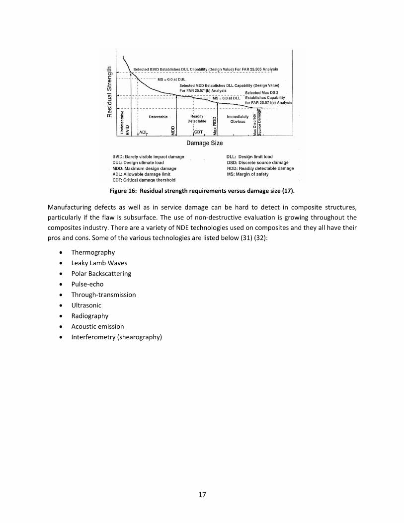
the size of a flaw and the residual strength of the structure. This can be seen in the Figure 16 below.
It follows then that the larger the strength reduction is, the sooner the damage should be detected.
Furthermore, these methods also consider that the need for inspection cannot disregard the likelihood
of damage occurrence. The more likely the damage is, the sooner it should be detected. As a result,
these methods depend on service data (17).
17
Figure 16: Residual strength requirements versus damage size (17).
Manufacturing defects as well as in service damage can be hard to detect in composite structures,
particularly if the flaw is subsurface. The use of non‐destructive evaluation is growing throughout the
composites industry. There are a variety of NDE technologies used on composites and they all have their
pros and cons. Some of the various technologies are listed below (31) (32):
Thermography
Leaky Lamb Waves
Polar Backscattering
Pulse‐echo
Through‐transmission
Ultrasonic
Radiography
Acoustic emission
Interferometry (shearography)
18
III. RECOMMENDATIONS
The particular focus of the effort will perform quantitative analysis based on the past performance of
wind turbine blades. The key elements to consider in a reliability study of past performance are (14):
(1) Identify areas needing structural and/or procedural reinforcement or modification
(2) Establish chronological trends in reliability performance
(3) Establish existing indices to serve as a guide for acceptable values in future reliability
assessments
(4) Enable previous predictions to be compared with actual operating experience
(5) Monitor the response to system design changes
Since the aviation industry has established many probabilistic design models, similar approaches should
be utilized. In order to begin this process two parallel efforts are recommended: Flaw Characterization
and Effects of Defects.
A. Flaw Characterization
In order to develop a quality blade reliability program based on the implications of composite flaws, a
study must be performed into composite defects as they relate to the wind turbine industry. Variations
will exist in the type, frequency and effects of flaws between this industry and others. Therefore, it is
imperative that data be generated specifically for wind turbine blades.
i. Collect Flaw Data ad Develop Database
Data should be collected from industry in the form of surveys to address the following topics:
Flaw Type & Size Frequency
Flaw Location Frequency
Materials & Ply schedule
Evaluation Techniques Utilized
Frequency of Failures attributable to flaws
Failure Mode
This data should then be assimilated into a database which will allow for ease of access through search
fields and the implementation of a grouping criterion.
ii. Investigation into Non‐Destructive Evaluation Technology
As stated earlier, flaw size is correlated to the strength of a structure and it is imperative that the right
NDE technology be used. An investigation into the applicability of various NDE technologies on wind
turbine blades should be performed. The results of this investigation should discuss the limitations of
the different technologies as it relates to flaw size, type and location.
iii. Classification of Wind Turbine Specific Defects and Their Origin
Once the survey and NDE data has been assimilated, it will be necessary to distill it into bins that can be
investigated further. This classification of flaw events will enable statistical interpretation of the
criticality of various categories. Many factors will affect the categorization of events such as frequency,
19
implications to structural design capacity, susceptibility to environmental influences, reparability, failure
mode and generic effects of defect analysis.
iv. Statistical Interpretation of Defect Relevance & Criticality
With the complete database established it becomes necessary to evaluate the criticality of flaws. Where
quantifiable data is not available a simple approach to performance measurement is to apply Pugh or
Rank Reciprocal methods. These methods allow for the prioritization of the various criteria relative to
each other. Each data bin is then ranked in terms of severity for each criterion. The result of the analysis
is a fairly objective ranking of importance for the flaw bins. These results will be combined with
statistically relevant frequency data to yield a metric that develops a probabilistic approach to predicting
the leading cause of failure.
i. Probabilistic Modeling
Variations in the structural behavior of composites cannot be characterized by the traditional
deterministic methods that utilize a safety factors to account for uncertain structural behavior. The
result of this dilemma is that structural reliability cannot be quantified. A design methodology that
incorporates probabilistic modeling is needed to accurately determine the structural reliability of a
composite structure (33).
ii. Directives Database
Should large amounts of data be collected, particularly from operators on a variety of machines and
blade models it may be possible to set up an inspection database similar to that of the FAA
Airworthiness Directives (AD) database. The AD database consists of inspection protocols specific to
aircrafts or components. Non‐specificity could be possible if the data collected showed strong
inclinations to typical failure locations and modes that are industry wide problems. A series of directives
(or recommendations) could then be developed by a standards committee which applies to all blades.
iii. Generation of Distributable Defect Characterization Criteria and Flaw‐to‐Failure Code
The potential may exist to distribute a flaw catalog which would be a visual database of flaw types, size
and location which a technician could use to place an observed flaw into a class. This could help speed
flaw evaluations and reduce the potential for incorrect classification. Another tool could be developed
that incorporates damage growth/residual strength models to further predict the potential for failure.
B. Effects of Defects
As noted above, current research indicates that determining critical size, type, location and
combinations of flaws is needed to ensure proper design life. It has been proposed that this will be
achieved by the following steps:
i. Understand critical flaw types.
Before the effects of defects can be determined, the critical flaw types must be identified from the flaw
database and probabilistic modeling. This will occur in conjunction with the flaw characterization efforts
noted above. In addition, a comprehensive review of relevant literature will be performed to ensure that

20
as much background information can be gleaned potentially reducing the workload of the latter portions
of this research.
ii. Characterize the mechanical properties of common flaws deemed critical to composite blades.
Characterization will rely on static testing, both in‐plane static and out‐of‐plane, utilizing the strengths of
the entire MSUGC. As a parallel path, a model will also be generated and will rely on physical testing
results. Fatigue testing may be utilized in latter portions of the research. A digital imagine correlation
system (ARAMIS) will be utilized to understand stress‐strain mapping associated with each flaw type.
iii. Determine the criteria at criticality threshold of each flaw type.
Criticality of flaw type, size and location will be determined for each flaw type such that it can be added
to the flaw database to assist in quality control efforts.
iv. Use a three‐round study to develop coordinated analytical and experimental analogs for damage growth and residual strengths necessary for blade reliability.
The first round will rely on input from other members of the BRC to determine the types of flaws that
will be characterized. Characterization will rely on static testing, both in‐plane static and out‐of‐plane,
utilizing the strengths of the entire MSUGC. As a parallel path, a model will also be generated and will
rely on physical testing results. This round will be complete when the model is able to somewhat
accurately predict failure of a flaw‐scale sample. Upon completion of this round an interim report of the
results will be compiled, including specific paths for the second round.
Generally, the second round will be further coordination of experimental and analytical results and the
third round will focus on an approach validation for the entire structure. Each round will culminate in a
report which will include specific paths for the following round and recommendations, respectively.
Other members of the BRC will be allowed to observe and testing will be coordinated to allow for group
goals to be met. For example, testing may be interrupted to allow for NDE inspections by other group
members. In short, this testing will not entirely take place as an independent project.
v. Understand and model how these flaws contribute to the entire structure.
Crucial to the outcome of this entire portion of the project is the modeling capabilities that will be
generated. The intended outcome will be the ability to model flaws specific to an individual blade
allowing for quality control a tool to act as a go/no‐go gage. Users, likely quality control technicians, will
enter critical flaw information for each flaw known to exist in the entire structure while consistent flaws
(e.g. ply drops) will be embedded. The model will then analyze and evaluate the damage and output
residual strength and durability information. This tool will be a significant improvement and a step
toward implementing probabilistic and damage tolerance methodologies the wind industry needs.
21
REFERENCES
1. AWEA. AWEA Annual Report for the 2008 Year Ending. 2009.
2. Red, C. Wind turbine blades: Big and getting bigger. Composites World. 2008.
3. Department of Energy. 20% wind Energy by 2030: Increasing Wind Energy's Contribution to US
Electricity Supply. July 2008. DOE/GO‐102008‐2567.
4. Barbero, Ever J. Introduction to Composite Materials Design. Ann Arbor, MI : Taylor & Francis, 1998.
ISBN 1‐56032‐701‐4.
5. Alternative Composite Materials for Megawatt‐Scale Wind Turbine Blades. Griffin, A. & Ashwill, T.
0696, s.l. : American Institute of Aeronautics, 2003.
6. Verrengia, J. NREL Gearbox Study Aims to Grease Wind Power's Future. NREL Newsroom. April 17,
2009.
7. Sandia Blade Workshop. Veers, P. & Hill, R. s.l. : Sandia National Labratory, May 2008.
8. Cairns, D. Personal correspondance with wind turbine OEMs & blade manufactures.
9. Staff. Suzlon Blade Recall: Retrofit Program to Address Cracking. Composites World. Feburary 2010.
10. Freeman, S. Boeing Hits a Hitch in 'Dreamliner' Fuselage. Washington Post. August 2009.
11. Mandell, John F, et al. Analysis of SNL/MSU/DOE Fatigue Database Trends for Wind Turbine Blade
Materials. Bozeman, MT : Montana State University, 2009. SAND2009‐XXXX.
12. Improved Wind Turbine Blade Reliabilty. Cairns, D. s.l. : Sandia Wind Turbine Blade Workshop, 2009.
13. Hertzberg, R. Deformation and Fracture Mechanics of Engineering Materials, 4th ed. New York : John
Wiley & Sons, 1996.
14. Billington, R. & Allan, R. Reliability Evaluation of Engineering Systems. New York : Plenum Press,
1992.
15. Low Cost Inspection for Improved Blade Reliability. Cairns, D. s.l. : Sandia Blade Workshop, 2008.
16. Cairns, D. & Mohaghegh, M. Aircraft Structures. s.l. : MSU/Boeing ME458 Course , 2009.
17. Defense, Department Of. COMPOSITE MATERIALS HANDBOOK. s.l. : DOD. MIL‐HDBK‐17‐3F.
18. Administration, Federal Aviation. Composite Aircraft Structure. s.l. : U.S. Department of
Transportation, Septemeber 8, 2009. AC: 20‐107B.
19. Grande, Joseph A. Wind Power Blades Energize Composites Manufacturing. ptonline.com.
20. Richardson, R. Wind Turbine Blade Composites Design: Leveraging Aerospace Advances for Improved
Durability. s.l. : Dassault Systems, 2009.
21. Dvorak, P. Lay‐up equipment cuts 85% off time to manufacturer big blades. Windpower Engineering.
June 1, 2009.
22. Mandell, J F, Samborsky, D D and Cairns, D. Fatigue of composite materials and substructures for
wind turbine blades. Albuquerque, NM : Sandia National Labs, 2002. SAND2002‐0771.
23. Effects of layer waviness on the compression strength of thermoplastic laminates. Adams, D O and
Hyer, M W. 4, s.l. : Journal of Reinforced Composites, 1993, Vol. 12.

22
24. The influence of ply waviness with nonlinear shear of the stiffness and strength reduction of
composite laminates. Bogetti, TA, Gillespie, JW and Lamontia, MA. 2, s.l. : Journal of Thermoplastic
Composite Materials, 1994, Vol. 7.
25. Compression strength of carbon fiber laminates containing flaws with fiber waviness. Avery, DP, et
al. s.l. : 42nd AIAA Aerospace Sciences Meeting and Exhibit, 2004.
26. Design considerations for ply drops in composite wind turbine blades. Cairns, DS, et al. Reno, NV :
35th AIAA Aerospace Sciences Meeting & Exhibit, 1997.
27. Prediction of delamination in wind turbine structural details. Mandell, JF, et al. s.l. : Journal of Solar
Energy Engineering, 2003, Vol. 125.
28. Composite Materials Fatigue Issues in Wind Turbine Blade Construction. Mandell, JF, Samborsky, DD
and Agastra, P. s.l. : SAMPE, 2008.
29. Quantification of processing parameters for wind turbine blades. Cairns, D, Mandell, J and
Samborsky, D. Reno, NV : 41st AIAA Aerospace Science Meeting and Exhibit, 2002.
30. Administration, Federal Aviation. Advisory Circular: Quality Control for the Manufacture of
Composite Structures. s.l. : Department of Transportation, 1989. AC21‐26.
31. Emerging NDE Technology and Challenges at the beginning of the 3rd Millennium. Bar‐Cohen, Y. 2,
s.l. : NDT.net, 2000, Vol. 5.
32. Non‐destructive Evaluation (NDE) Methods for Inspecting the Integrity of Composuite Structures in
the Offshore Oil Industry. Ochoa, O. s.l. : NDE Composites Workshop, 2002.
33. Chamis, C. Probabilistic design of Composite Structures. s.l. : NASA/TM, 2006. 2006‐214660.
23
Distribution 3 Cece Sterling Attention: Mark Higgins Mike Derby John Meissner Wind & Hydropower Technologies EE‐2B Forrestal Building U.S. Department of Energy 1000 Independence Ave. SW Washington, DC 20585 1 NREL Scott Hughes – MS 3911 1617 Cole Blvd Golden, CO 80401 1 NREL Derek Berry – MS 3911 1617 Cole Blvd Golden, CO 80401 1 NREL Paul Veers – MS 3811 1617 Cole Blvd Golden, CO 80401 3 Douglas S. Cairns Mechanical & Industrial Engineering Montana State University ‐ Bozeman PO Box 173800 320 Roberts Hall Bozeman, MT 59717‐3800 1 MS 1124 J. Paquette 6121 1 MS 1124 T. Ashwill 6121 1 MS 1124 B. McKenney 6121 1 MS 1124 A. Ogilvie 6121 1 MS 0615 D. Roach 6620 1 MS 0615 K. Rackow 6620 1 MS 1104 J. Zayas 6120 1 MS 0899 Technical Library 9536 (electronic copy)

24

Recommended