All types
C
"The repair methods given by the manufacturer in this document arebased on the technical specifications current when it was prepared.
The methods may be modified as a result of changes by the manufacturerin the production of the various component units and accessories fromwhich his vehicles are constructed".
All copyrights reserved by Renault.
Copying or translating, in part or in full, of this document or use of theservice part reference numbering system is forbidden without the priorwritten authority of Renault.
77 11 196 407 OOOOCCCCTTTTOOOOBBBBEEEERRRR 1111999999997777 Edition Anglaise
Renault 1997
INSTRUMENT PANEL
N.T. 2863A
Basic manual: M.R. 302 - M.R. 307 - M.R. 311 - M.R. 312
M.R. 291 - M.R. 293
Workshop Repair Manual

ContentsPages
• Instrument panel with or without tripcomputer
All typesFault finding - IntroductionFault finding - Customer complaintsFault finding charts
• Conventional instrument panel with tripcomputer
MéganeFault finding - Customer complaintsFault finding charts
Safrane except GB versionFault finding - Customer complaintsFault finding charts
Safrane GB versionFault finding - Customer complaintsFault finding charts
LagunaFault finding - Customer complaintsFault finding charts
83-183-283-4
83-2183-22
83-3283-33
83-5183-52
83-7083-71
INSTRUMENT PANEL83

ntt1106.0
INSTRUMENT PANELInstrument panel with or without trip computer 83AAAALLLLLLLL TTTTYYYYPPPPEEEESSSS
FFFFAAAAUUUULLLLTTTT FFFFIIIINNNNDDDDIIIINNNNGGGG ---- IIIINNNNTTTTRRRROOOODDDDUUUUCCCCTTTTIIIIOOOONNNN
PPPPRRRREEEECCCCAAAAUUUUTTTTIIIIOOOONNNN
When carrying out checks using a multimeter, avoid using a contact point on the connectors the size of whichcould damage the clips and result in poor contact.
For all checks and measurements carried out on the 30-way connector of certain instrument panels, alwaysuse bornier Elé. 1302.
Bornier Elé. 1302 enables:
- continuities to be checked. To do this, simply connect the bornier to the 30-way instrument panel connec-tor or to the connector at the vehicle wiring end,
- voltages or frequencies to be measured, frequencies to be generated, etc... To do this, connect the bornierin series between the instrument panel unit and the connector at the vehicle wiring end.
83-1

ntt1106.0
INSTRUMENT PANELInstrument panel with or without trip computer 83AAAALLLLLLLL TTTTYYYYPPPPEEEESSSS
FFFFAAAAUUUULLLLTTTT FFFFIIIINNNNDDDDIIIINNNNGGGG ---- CCCCUUUUSSSSTTTTOOOOMMMMEEEERRRR CCCCOOOOMMMMPPPPLLLLAAAAIIIINNNNTTTTSSSS
Refer to the "Fault finding - Introduction" section before beginning this faultfinding procedure.
NOTES
DIESEL REV COUNTER PROBLEM
No needle movement or needle vibrates or oscillates CCCCHHHHAAAARRRRTTTT 1111
PETROL REV COUNTER PROBLEM
No needle movement or needle vibrates or oscillates
SPEEDOMETER PROBLEM (vehicles fitted with a speedometer cable)
CCCCHHHHAAAARRRRTTTT 3333
CCCCHHHHAAAARRRRTTTT 4444
CCCCHHHHAAAARRRRTTTT 5555
CCCCHHHHAAAARRRRTTTT 6666
Needle oscillates or total mileage recorder is noisy
No needle movement and total mileage recorder does not operate
Needle sticks (for example: at 80 km/h) but total mileage recorderoperates
No needle movement but total mileage recorder operates or needlemovement correct but total mileage recorder does not operate
SPEEDOMETER PROBLEM (vehicles fitted with an electric speedometer)
Needle vibrates or oscillates or no needle movement and total mileagerecorder does not operate
No needle movement, but total mileage recorder operates or needlemovement correct but total mileage recorder does not operate
CCCCHHHHAAAARRRRTTTT 7777
CCCCHHHHAAAARRRRTTTT 8888
FFFFUUUUEEEELLLL LLLLEEEEVVVVEEEELLLL RRRREEEECCCCEEEEIIIIVVVVEEEERRRR PPPPRRRROOOOBBBBLLLLEEEEMMMM
CCCCHHHHAAAARRRRTTTT 9999
CCCCHHHHAAAARRRRTTTT 11110000
No fuel level information on needle receiver(tank not empty)
Fuel level receiver needle remains stuck in the maximum position(ignition on) when the tank is not full
CCCCHHHHAAAARRRRTTTT 2222
83-2

ntt1106.0
INSTRUMENT PANELInstrument panel with or without trip computer 83AAAALLLLLLLL TTTTYYYYPPPPEEEESSSS
FFFFAAAAUUUULLLLTTTT FFFFIIIINNNNDDDDIIIINNNNGGGG ---- CCCCUUUUSSSSTTTTOOOOMMMMEEEERRRR CCCCOOOOMMMMPPPPLLLLAAAAIIIINNNNTTTTSSSS
Refer to the "Fault finding - Introduction" section before beginning this faultfinding procedure.
NOTES
COOLANT TEMPERATURE RECEIVER PROBLEM
No needle movement CCCCHHHHAAAARRRRTTTT 11115555
OIL LEVEL RECEIVER PROBLEM
CCCCHHHHAAAARRRRTTTT 11111111
CCCCHHHHAAAARRRRTTTT 11112222
CCCCHHHHAAAARRRRTTTT 11113333
CCCCHHHHAAAARRRRTTTT 11114444
No needle movement and no lighting of the level and temperaturescale
Needle operates correctly but scale does not light up
Lighting of the scale correct but no needle movement
Graduation of combined oil level indicator does not light up whenignition is switched on and display passes straight to general totalmileage recorder (MEGANE except Scénic)
83-3

no
ntt1106.0
INSTRUMENT PANELInstrument panel with or without trip computer 83AAAALLLLLLLL TTTTYYYYPPPPEEEESSSS
Connect the XR25 and use the diesel injection fault finding fiche. With the engine running, check that the engine speed value read on the revcounter corresponds to the value displayed on the XR25. Check that all the instrument panel functions operate correctly.
AFTER
REPAIR
FFFFAAAAUUUULLLLTTTT FFFFIIIINNNNDDDDIIIINNNNGGGG CCCCHHHHAAAARRRRTTTTSSSS
CHART 1DIESEL REV COUNTER PROBLEM
No rev counter needle movement or needle vibrates or oscillates onthe instrument panel
Check that the system connectors are engaged correctly.Take care not to damage the connectors during checks.Check that the engine earth is in good condition.
NOTES
yes
Is the vehicle concerned a SAFRANE withengine G8T ?
no A
Disconnect the injection computer connectorwhich includes the "rev counter"information. Connect the XR25.
Use the frequency generation function(key G, output terminal G). Connect the
frequency generator wire to the"rev counter" information track of the
connector (connector wiring end). With the ignition on, enter on the XR25 :- , the rev counter should
indicate ~ 860 rpm.- , the rev counter should
indicate ~ 1250 rpm.- , the rev counter should
indicate ~ 1700 rpm.Does the rev counter needle indicate
these values?
G 4
G 6
G 8
yes
Check the continuity and absence of shortcircuits of the electrical wiring between the
injection computer "rev counter" output andthe instrument panel.
Is the electrical wiring in good condition?
yes Refer to the "Diesel injection" fault findingprocedure which corresponds to the vehicle.
no Repair the electrical wiring.
Change the rev counter or the instrumentpanel depending on instrument panel model.
83-4

Disconnect the "rev counter information"connector located on the alternator.
Connect the XR25.Use the frequency generation function(key G, output terminal G). Connect the
frequency generator wire to the"rev counter" information track of the
connector (connector wiring end). With the ignition on, enter on the XR25 :- , the rev counter should
indicate ~ 860 rpm.- , the rev counter should
indicate ~ 1250 rpm.- , the rev counter should
indicate ~ 1700 rpm.Does the rev counter needle indicate
these values?
ntt1106.0
INSTRUMENT PANELInstrument panel with or without trip computer 83AAAALLLLLLLL TTTTYYYYPPPPEEEESSSS
Adjust the various instrument panel functions (clock, etc...) if necessary.Check that all the instrument panel functions operate correctly.
AFTER
REPAIR
FFFFAAAAUUUULLLLTTTT FFFFIIIINNNNDDDDIIIINNNNGGGG CCCCHHHHAAAARRRRTTTTSSSS
CHART 1CONT
A
no
yes
G 4
G 6
G 8
yes
yes Change the alternator.
no Repair the electrical wiring.
Check whether the "rev counter" outputconnector located on the alternator is
connected correctly.Is the connector connected correctly?
noConnect the connector on the alternator
correctly.
Check the continuity and absence of shortcircuits of the electrical wiring between the
alternator "rev counter" output and theinstrument panel.
Is the electrical wiring in good condition?
Change the rev counter or the instrumentpanel depending on instrument panel model.
83-5

no
Connect the XR25. Disconnect the injectioncomputer connector and connect thecorresponding bornier in its place.
Use the frequency generation function(key G, output terminal G). Connect the
frequency generator wire to the "rev counterinformation" output on the bornier.
With the ignition on, enter on the XR25 :- , the rev counter should
indicate: ~ 1500 rpm for 4, 5and 6 cylinder engines (L7X).~ 1000 rpm for 6 cylinderengines (Z7X).
- , the rev counter shouldindicate: ~ 4500 rpm for 4, 5and 6 cylinder engines (L7X).~ 3000 rpm for 6 cylinderengines (Z7X).
- , the rev counter shouldindicate: ~ 7500 rpm for 4, 5and 6 cylinder engines (L7X).~ 5000 rpm for 6 cylinderengines (Z7X).
Does the rev counter needle indicatethese values?
ntt1106.0
INSTRUMENT PANELInstrument panel with or without trip computer 83AAAALLLLLLLL TTTTYYYYPPPPEEEESSSS
AFTER
REPAIR
FFFFAAAAUUUULLLLTTTT FFFFIIIINNNNDDDDIIIINNNNGGGG CCCCHHHHAAAARRRRTTTTSSSS
CHART 2PETROL REV COUNTER PROBLEM
No rev counter needle movement or needle vibrates or oscillates onthe instrument panel
NOTES
G 1
G 3
G 5
yes
no Repair the electrical wiring.
Check that the system connectors are engaged correctly.Take care not to damage the connectors during checks.Check that the engine earth is in good condition.
yes
Check the continuity and absence of shortcircuits of the electrical wiring between the
injection computer "rev counter" output andthe instrument panel.
Is the electrical wiring in good condition?
Change the rev counter or the instrumentpanel depending on instrument panel model.
Refer to the "Petrol injection" fault findingprocedure which corresponds to the vehicle
or change the electronic ignition moduledepending on the vehicle.
Adjust the various instrument panel functions (clock, etc...) if necessary.Check that all the instrument panel functions operate correctly.
83-6

ntt1106.0
INSTRUMENT PANELInstrument panel with or without trip computer 83AAAALLLLLLLL TTTTYYYYPPPPEEEESSSS
AFTER
REPAIR
FFFFAAAAUUUULLLLTTTT FFFFIIIINNNNDDDDIIIINNNNGGGG CCCCHHHHAAAARRRRTTTTSSSS
CHART 3SPEEDOMETER PROBLEM
(vehicles fitted with a speedometer cable)Needle oscillates or total mileage recorder is noisy
Check that the system connectors are engaged correctly.Before beginning this fault finding procedure, set the trip recorder to zero thencheck whether the customer complaint persists.
NOTES
Check that the whole length of the cable is free (no stress) with the largest radii of curvature possible.Repair or change the speedometer cable if necessary.Reminder: the addition of grease to the cable at the speedometer end is prohibited as grease rises andcauses the needle to stick.
If the customer complaint persists, change the speedometer or the instrument panel depending oninstrument panel model.
Adjust the various instrument panel functions (clock, etc...) if necessary.Check that all the instrument panel functions operate correctly.
83-7

ntt1106.0
INSTRUMENT PANELInstrument panel with or without trip computer 83AAAALLLLLLLL TTTTYYYYPPPPEEEESSSS
AFTER
REPAIR
FFFFAAAAUUUULLLLTTTT FFFFIIIINNNNDDDDIIIINNNNGGGG CCCCHHHHAAAARRRRTTTTSSSS
CHART 4
NOTES
no Repair.
yes
Unclip the speedometer cable at thespeedometer end, then turn the cable
manually and check whether it turns correctlywith no stress.
Does the cable turn without stress?
non
Check the condition of the speedometercable and change it if necessary.
Check that the speed sensor is correctlysecured to the gearbox.
yes
SPEEDOMETER PROBLEM(vehicles fitted with a speedometer cable)
No needle movement and total mileage recorder does not operate
Check that the system connectors are engaged correctly.Before beginning this fault finding procedure, set the trip recorder to zero thencheck whether the customer complaint persists.
Check the connection of the speedometercable to the gearbox and the speedometer.
Is it connected correctly?
Change the speedometer or the instrumentpanel depending on instrument panel model.
Adjust the various instrument panel functions (clock, etc...) if necessary.Check that all the instrument panel functions operate correctly.
83-8

ntt1106.0
INSTRUMENT PANELInstrument panel with or without trip computer 83AAAALLLLLLLL TTTTYYYYPPPPEEEESSSS
AFTERREPAIR
FFFFAAAAUUUULLLLTTTT FFFFIIIINNNNDDDDIIIINNNNGGGG CCCCHHHHAAAARRRRTTTTSSSS
CHART 5
NOTES
SPEEDOMETER PROBLEM(vehicles fitted with a speedometer cable)
Needle sticks (eg.: at 80 km/h) but total mileage recorder operates
Check that the system connectors are engaged correctly.Before beginning this fault finding procedure, set the trip recorder to zero thencheck whether the customer complaint persists.
Check that the whole length of the cable is free (no stress) with the largest radii of curvature possible.Repair or change the speedometer cable if necessary.Reminder: the addition of grease to the cable at the speedometer end is prohibited as grease rises andcauses the needle to stick.
If the customer complaint persists, change the speedometer or the instrument panel depending oninstrument panel model.
Adjust the various instrument panel functions (clock, etc...) if necessary.Check that all the instrument panel functions operate correctly.
83-9

ntt1106.0
INSTRUMENT PANELInstrument panel with or without trip computer 83AAAALLLLLLLL TTTTYYYYPPPPEEEESSSS
AFTERREPAIR
FFFFAAAAUUUULLLLTTTT FFFFIIIINNNNDDDDIIIINNNNGGGG CCCCHHHHAAAARRRRTTTTSSSS
CHART 6SPEEDOMETER PROBLEM (vehicles fitted with a speedometer cable).
No needle movement, but total mileage recorder operates or needle movementcorrect but total mileage recorder does not operate
Check that the system connectors are engaged correctly.Reminder: the addition of grease to the cable at the speedometer end is prohibitedas grease rises and causes the needle to stick.
NOTES
If the customer complaint persists, change the speedometer or the instrument panel depending oninstrument panel model.
Adjust the various instrument panel functions (clock, etc...) if necessary.Check that all the instrument panel functions operate correctly.
83-10

Disconnect the speed sensor connector.Connect the XR25.
Use the frequency generation function(key G, output terminal G). Connect the
frequency generator wire to the"vehicle speed" input of the connector
(connector wiring end). With the ignition on, enter on the XR25:- , the rev counter should
indicate ~ 36 rpm.- , the rev counter should
indicate ~ 108 rpm.- , the rev counter should
indicate ~ 180 rpm.Does the rev counter needle indicate
these values without vibrating or oscillating?
ntt1106.0
INSTRUMENT PANELInstrument panel with or without trip computer 83AAAALLLLLLLL TTTTYYYYPPPPEEEESSSS
except N engine
AFTER
REPAIR
FFFFAAAAUUUULLLLTTTT FFFFIIIINNNNDDDDIIIINNNNGGGG CCCCHHHHAAAARRRRTTTTSSSS
no
CHART 7SPEEDOMETER PROBLEM (vehicles fitted with an electric speedometer).
Needle vibrates or oscillates or no needle movement andtotal mileage recorder does not operate
NOTES
yes
Check that the speed sensor is connected andsecured correctly.
Is the speed sensor secured correctly?no
G 1
G 3
G 5
yes
Change the speedometer or the instrumentpanel depending on instrument panel model.
Check the condition of the electrical wiringbetween the speed sensor and the "vehicle
speed" input on the instrument panel.Is the electrical wiring in good condition?
yes Change the speed sensor.
no Repair the electrical wiring between theinstrument panel and the speed sensor.
Secure the speed sensor correctly.
Check that the system connectors are engaged correctly.Take care not to damage the connectors during checks.
Adjust the various instrument panel functions (clock, etc...) if necessary.Check that all the instrument panel functions operate correctly.
83-11

no
Disconnect the speed sensor connector.Connect the XR25.
Use the frequency generation function(key G, output terminal G). Connect the
frequency generator wire to the"vehicle speed" input of the connector
(connector wiring end). With the ignition on, enter on the XR25:- , the rev counter should
indicate ~ 36 rpm.- , the rev counter should
indicate ~ 108 rpm.- , the rev counter should
indicate ~ 180 rpm.Does the rev counter needle indicate
these values without vibrating or oscillating?
ntt1106.0
INSTRUMENT PANELInstrument panel with or without trip computer 83
AFTER
REPAIR
FFFFAAAAUUUULLLLTTTT FFFFIIIINNNNDDDDIIIINNNNGGGG CCCCHHHHAAAARRRRTTTTSSSS
CHART 8SPEEDOMETER PROBLEM (vehicles fitted with an electric speedometer).
No needle movement, but total mileage recorder operates or needle movementcorrect but total mileage recorder does not operate.
NOTES
yes
no
G 1
G 3
G 5
yes
Change the speedometer or the instrumentpanel depending on instrument panel model.
yes Change the speed sensor.
no Repair the electrical wiring between theinstrument panel and the speed sensor.
Secure the speed sensor correctly.
AAAALLLLLLLL TTTTYYYYPPPPEEEESSSSexcept N engine
Check that the system connectors are engaged correctly.Take care not to damage the connectors during checks.
Check that the speed sensor is connected andsecured correctly.
Is the speed sensor secured correctly?
Check the condition of the electrical wiringbetween the speed sensor and the "vehicle
speed" input on the instrument panel.Is the electrical wiring in good condition?
Adjust the various instrument panel functions (clock, etc...) if necessary.Check that all the instrument panel functions operate correctly.
83-12

ntt1106.0
INSTRUMENT PANELInstrument panel with or without trip computer 83AAAALLLLLLLL TTTTYYYYPPPPEEEESSSS
AFTERREPAIR
FFFFAAAAUUUULLLLTTTT FFFFIIIINNNNDDDDIIIINNNNGGGG CCCCHHHHAAAARRRRTTTTSSSS
CHART 9FUEL LEVEL PROBLEM
No fuel level information on needle receiver(tank not empty)
NOTES
no Connect the connector correctly.
yes
Check that the gauge connector is connectedcorrectly.
Is the connector connected correctly?
yes Check the condition of the fuel gauge andchange it if necessary.
no
no Repair the faulty electricalwiring.
With the gauge connector disconnected andthe ignition on, shunt the tracks of the
connector which correspond to earth and"gauge information" to the instrument panel
(wiring end of the connector). Does the receiver needle rise to maximum?
yes
Check the continuity of the electrical wiringwhich corresponds to:
- the gauge earth,- the "gauge information" to the
instrument panel.Is the electrical wiring in good condition?
no Change the connector.
yes
Change the fuel level receiver or theinstrument panel depending on instrument
panel model.
Check the condition of the connector on theinstrument panel and its pins.
Is the connector in good condition?
Check that the system connectors are engaged correctly.Take care not to damage the connectors during checks.
Adjust the various instrument panel functions (clock, etc...) if necessary.Check that all the instrument panel functions operate correctly.
83-13

ntt1106.0
INSTRUMENT PANELInstrument panel with or without trip computer 83AAAALLLLLLLL TTTTYYYYPPPPEEEESSSS
AFTERREPAIR
FFFFAAAAUUUULLLLTTTT FFFFIIIINNNNDDDDIIIINNNNGGGG CCCCHHHHAAAARRRRTTTTSSSS
CHART 10FUEL LEVEL PROBLEM
Fuel level receiver needle remains stuck in the maximum position......(ignition on), tank not full
NOTES
no Connect the connector correctly.
yes
yes Check the condition of the fuel gauge andchange it if necessary.
no
no Repair the faulty electricalwiring.
With the ignition on, disconnect the fuelgauge connector. Does the needle fall to the
minimum position?
yes
no Change the connector.
yes
Change the fuel level receiver or theinstrument panel depending on instrument
panel model.
Check that the system connectors are engaged correctly.Take care not to damage the connectors during checks.
Check the condition of the connector on theinstrument panel and its pins.
Is the connector in good condition?
Check that there are no short circuits of theelectrical wiring which corresponds to:
- the gauge earth,- the "gauge information" to the
instrument panel.Is the electrical wiring in good condition?
Check that the gauge connector is connectedcorrectly.
Is the connector connected correctly?
Adjust the various instrument panel functions (clock, etc...) if necessary.Check that all the instrument panel functions operate correctly.
83-14

ntt1106.0
INSTRUMENT PANELInstrument panel with or without trip computer 83AAAALLLLLLLL TTTTYYYYPPPPEEEESSSS
AFTER
REPAIR
FFFFAAAAUUUULLLLTTTT FFFFIIIINNNNDDDDIIIINNNNGGGG CCCCHHHHAAAARRRRTTTTSSSS
CHART 11OIL LEVEL RECEIVER PROBLEM
No needle movement and no lighting of thelevel and temperature scale
NoneNOTES
Change the oil level receiver or the instrument panel depending on instrument panel model.
Adjust the various instrument panel functions (clock, etc...) if necessary.Check that all the instrument panel functions operate correctly.
83-15

ntt1106.0
INSTRUMENT PANELInstrument panel with or without trip computer 83AAAALLLLLLLL TTTTYYYYPPPPEEEESSSS
AFTER
REPAIR
FFFFAAAAUUUULLLLTTTT FFFFIIIINNNNDDDDIIIINNNNGGGG CCCCHHHHAAAARRRRTTTTSSSS
CHART 12 OIL LEVEL RECEIVER PROBLEMNeedle operates correctly, but scale does not light up
NoneNOTES
no Change the bulb.
yes
Change the oil level receiver or theinstrument panel depending on instrument
panel model.
Check the condition of the bulb on theinstrument panel (only in the case ofinstrument panels fitted with bulbs).
Is the bulb in good condition?
Adjust the various instrument panel functions (clock, etc...) if necessary.Check that all the instrument panel functions operate correctly.
83-16

ntt1106.0
INSTRUMENT PANELInstrument panel with or without trip computer 83AAAALLLLLLLL TTTTYYYYPPPPEEEESSSS
AFTER
REPAIR
FFFFAAAAUUUULLLLTTTT FFFFIIIINNNNDDDDIIIINNNNGGGG CCCCHHHHAAAARRRRTTTTSSSS
CHART 13 OIL LEVEL RECEIVER PROBLEMLighting of the scale correct, but no needle movement
Take care not to damage the connectors during checks.NOTES
no Connect the connector correctly.
yes
no Change the oil level sensor.
yes
yes Change the oil level sensor.
no
no Repair the faulty electrical wiring.
yes
Change the oil level receiver or theinstrument panel depending on instrument
panel model.
Check the continuity and absence of shortcircuits between the electrical wiring of the
oil level sensor connector and the instrumentpanel.
Is the electrical wiring in good condition?
Leave the oil level sensor connectordisconnected. Check whether there
is a short circuit to earth on the terminalsof the oil level sensor connector.
Is there a short circuit?
Disconnect the oil level sensor connector,then measure the resistance at its terminals.
The resistance measured should be5 ohms < R < 19 ohms.
Is the resistance measured between thesevalues?
Check that the oil level sensor is connectedcorrectly.
Is the connector connected correctly?
Adjust the various instrument panel functions (clock, etc...) if necessary.Check that all the instrument panel functions operate correctly.
83-17

ntt1106.0
INSTRUMENT PANELInstrument panel with or without trip computer 83MMMMEEEEGGGGAAAANNNNEEEE
except Scénic
AFTERREPAIR
FFFFAAAAUUUULLLLTTTT FFFFIIIINNNNDDDDIIIINNNNGGGG CCCCHHHHAAAARRRRTTTTSSSS
CHART 14OIL LEVEL RECEIVER PROBLEM
Graduation of combined oil level indicator does not light up when ignition isswitched on and display passes straight to general total mileage recorder
NOTES
no Connect the connector correctly.
yes
no Change the oil level sensor.
yes
yes Change the oil level sensor.
no
no Repair the faulty electricalwiring.
yes
Change the instrument panel.
The fault finding procedure which follows only applies to Mégane vehicles.Take care not to damage the connectors during checks.
Check that the oil level sensor is connectedcorrectly.
Is the connector connected correctly?
Disconnect the oil level sensor connector,then measure the resistance at its terminals.
The resistance measured should be4 ohms < R < 22 ohms.
Is the resistance measured between thesevalues?
Disconnect the oil level sensor connector.Check whether there is a
short circuit to earth on the terminalsof the oil level sensor connector.
Is there a short circuit?
Check the continuity and absence of shortcircuits between the electrical wiring of the
oil level sensor connector and the instrumentpanel.
Is the electrical wiring in good condition?
Adjust the various instrument panel functions (clock, etc...) if necessary.Check that all the instrument panel functions operate correctly.
83-18

yes
yes
ntt1106.0
INSTRUMENT PANELInstrument panel with or without trip computer 83AAAALLLLLLLL TTTTYYYYPPPPEEEESSSS
AFTER
REPAIR
FFFFAAAAUUUULLLLTTTT FFFFIIIINNNNDDDDIIIINNNNGGGG CCCCHHHHAAAARRRRTTTTSSSS
CHART 15 COOLANT TEMPERATURE RECEIVER PROBLEMNo needle movement
Take care not to damage the connectors during checks.NOTES
no Connect the connector correctly.Check that the coolant temperature sensor
connector is connected correctly.Is the connector connected?
yes
noRepair the faulty electrical
wiring.
no A
Adjust the various instrument panel functions (clock, etc...) if necessary.Check that all the instrument panel functions operate correctly.
Check that there are no short circuits of theelectrical wiring which corresponds to:
- the coolant temperature sensor earth,- the sensor coolant temperature
information output.Is the electrical wiring in good condition?
With the ignition on, connect the sensor"coolant temperature information" output
to earth and check that the needle rises to themaximum position. Leave the ignition on and
disconnect the coolant temperature sensorand check that the needle falls to the
minimum position. Does the needle rise to the maximum position
and fall to the minimum position duringthese tests?
Change the coolant temperature sensor.
83-19

ntt1106.0
INSTRUMENT PANELInstrument panel with or without trip computer 83AAAALLLLLLLL TTTTYYYYPPPPEEEESSSS
AFTER
REPAIR
FFFFAAAAUUUULLLLTTTT FFFFIIIINNNNDDDDIIIINNNNGGGG CCCCHHHHAAAARRRRTTTTSSSS
CHART 15CONT
A
no Repair.
yes
Change the coolant temperature receiver orthe instrument panel depending on
instrument panel model.
Check the condition of the connector on theinstrument panel and its pins.
Is the connector in good condition?
Adjust the various instrument panel functions (clock, etc...) if necessary.Check that all the instrument panel functions operate correctly.
83-20

ntt1106.0
INSTRUMENT PANELConventional instrument panel with trip computer 83MMMMEEEEGGGGAAAANNNNEEEE
FFFFAAAAUUUULLLLTTTT FFFFIIIINNNNDDDDIIIINNNNGGGG ---- CCCCUUUUSSSSTTTTOOOOMMMMEEEERRRR CCCCOOOOMMMMPPPPLLLLAAAAIIIINNNNTTTTSSSS
Refer to the "Fault finding - Introduction" section before beginning this faultfinding procedure.
NOTES
FFFFLLLLAAAASSSSHHHHIIIINNNNGGGG DDDDAAAASSSSHHHHEEEESSSS DDDDIIIISSSSPPPPLLLLAAAAYYYYEEEEDDDD IIIINNNN PPPPLLLLAAAACCCCEEEE OOOOFFFF RRRRAAAANNNNGGGGEEEE
FFFFLLLLAAAASSSSHHHHIIIINNNNGGGG DDDDAAAASSSSHHHHEEEESSSS SSSSOOOOMMMMEEEETTTTIIIIMMMMEEEESSSS DDDDIIIISSSSPPPPLLLLAAAAYYYYEEEEDDDD IIIINNNN PPPPLLLLAAAACCCCEEEE OOOOFFFF RRRRAAAANNNNGGGGEEEE
IIIINNNNCCCCOOOORRRRRRRREEEECCCCTTTT RRRRAAAANNNNGGGGEEEE DDDDIIIISSSSPPPPLLLLAAAAYYYY
SSSSEEEEVVVVEEEERRRRAAAALLLL FFFFUUUUNNNNCCCCTTTTIIIIOOOONNNNSSSS RRRREEEEPPPPLLLLAAAACCCCEEEEDDDD BBBBYYYY FFFFLLLLAAAASSSSHHHHIIIINNNNGGGG DDDDAAAASSSSHHHHEEEESSSS ((((eeeexxxxcccceeeepppptttt ddddiiiieeeesssseeeellll))))
OOOOIIIILLLL LLLLEEEEVVVVEEEELLLL DDDDIIIISSSSPPPPLLLLAAAAYYYY IIIINNNNCCCCOOOORRRRRRRREEEECCCCTTTT BBBBUUUUTTTT TTTTOOOOTTTTAAAALLLL DDDDIIIISSSSTTTTAAAANNNNCCCCEEEE DDDDIIIISSSSPPPPLLLLAAAAYYYYEEEEDDDD
NNNNEEEEIIIITTTTHHHHEEEERRRR OOOOIIIILLLL LLLLEEEEVVVVEEEELLLL NNNNOOOORRRR TTTTOOOOTTTTAAAALLLL DDDDIIIISSSSTTTTAAAANNNNCCCCEEEE DDDDIIIISSSSPPPPLLLLAAAAYYYYEEEEDDDD
CCCCHHHHAAAARRRRTTTT 1111
CCCCHHHHAAAARRRRTTTT 2222
CCCCHHHHAAAARRRRTTTT 3333
CCCCHHHHAAAARRRRTTTT 4444
CCCCHHHHAAAARRRRTTTT 5555
CCCCHHHHAAAARRRRTTTT 6666
83-21

ntt1106.0
INSTRUMENT PANELConventional instrument panel with trip computer 83
AFTER
REPAIR
FFFFAAAAUUUULLLLTTTT FFFFIIIINNNNDDDDIIIINNNNGGGG CCCCHHHHAAAARRRRTTTTSSSS
CHART 1 FLASHING DASHES DISPLAYED IN PLACE OF RANGE
Instrument panel fault finding procedures are carried out with the ignition on.Change to fault finding sequence:- keep the zero reset / reset / trip computer advance button at the end of the
windscreen wiper stalk pressed and switch on the ignition. NOTES
Gauge failure detection.
Briefly press the button at the end of the winds-creen wiper stalk to select the required display.
Level of fuel remaining in the tank.Illumination of fuel low warning light.
and
Check that the gauge is connected correctly and check thecondition of the terminals and wires in the connector.
Gauge information cut-off.
With the ignition on, connect the wiresof tracks A1 and B1 of the gauge connec-tor. Does the trip computer indicate thetank full value?
no
Check the gauge andchange it if necessary.
yes no
yes
Success
Repair.Is the information given bythe trip computer correct?
A
MMMMEEEEGGGGAAAANNNNEEEE
poorgood
Adjust the various instrument panel functions (clock, etc...) if necessary.Check that all the instrument panel functions operate correctly.
83-22

ntt1106.0
INSTRUMENT PANELConventional instrument panel with trip computer 83
AFTER
REPAIR
FFFFAAAAUUUULLLLTTTT FFFFIIIINNNNDDDDIIIINNNNGGGG CCCCHHHHAAAARRRRTTTTSSSS
Check the condition and connections of the va-rious connectors below:- instrument panel clear connector,- white connector of switch holder P16 (black)
located on the upper section of the passengercompartment connection unit.
- clear and black connectors of the left rearconnection / connection unit P15 (blue) loca-ted on the lower section of the passengercompartment connection unit.
yes
no
yes
Repair.Is the information given bythe trip computer correct?
Success
no
A
yesno
Success
Repair.Is the information given bythe trip computer correct?
Check the continuity of the gauge0 Volt line between track A1 ofthe gauge connector and track A9of the clear connector of connec-tion P15 (blue) on the connectionunit.
Check the continuity of the"gauge information" line bet-ween track B1 of the gaugeconnector and track B4 of theblack connector of connection P15(blue) on the connection unit.
CCBB
Connect track B1 of the gauge connector to the vehi-cle earth.Is the information given by the trip computer correct?
CHART 1CONT 1
MMMMEEEEGGGGAAAANNNNEEEE
good
poor
good poor poor good
Adjust the various instrument panel functions (clock, etc...) if necessary.Check that all the instrument panel functions operate correctly.
83-23

ntt1106.0
INSTRUMENT PANEL
Conventional instrument panel with trip computer 83
AFTER
REPAIR
FFFFAAAAUUUULLLLTTTT FFFFIIIINNNNDDDDIIIINNNNGGGG CCCCHHHHAAAARRRRTTTTSSSS
CHART 1CONT 2
CB
Change the passenger compartment connection unit.
Check the continuity of the gauge 0 Volt line bet-ween track 10 of the white connector of switchholder P16 (black) and track 8 of the instrumentpanel clear connector.
Check the continuity of the "gauge information"line between track 6 of the white connector ofswitch holder P16 (black) and track 5 of the instru-ment panel clear connector.
yes no
Repair.Is the information given by thetrip computer correct?
Success
Change the instrument panel.
MMMMEEEEGGGGAAAANNNNEEEE
Adjust the various instrument panel functions (clock, etc...) if necessary.Check that all the instrument panel functions operate correctly.
goodpoorpoorgood
goodpoorpoorgood
Check the continuity of the gauge 0 Volt line through the passengercompartment connection unit bet-ween track A9 of the clear connectorand track 10 of the white connectorof switch holder P16 (black).
Check the continuity of the "gaugeinformation" line through the pas-senger compartment connection unitbetween track B4 of the black connec-tor and track 6 of the white connectorof switch holder P16 (black).
83-24

ntt1106.0
INSTRUMENT PANEL
Conventional instrument panel with trip computer 83
AFTER
REPAIR
FFFFAAAAUUUULLLLTTTT FFFFIIIINNNNDDDDIIIINNNNGGGG CCCCHHHHAAAARRRRTTTTSSSS
CHART 2 FLASHING DASHES SOMETIMES DISPLAYED IN PLACE
OF RANGE
NOTES
Gauge failure detection.
FFFFLLLLAAAASSSSHHHHIIIINNNNGGGG DDDDAAAASSSSHHHHEEEESSSS SSSSOOOOMMMMEEEETTTTIIIIMMMMEEEESSSS DDDDIIIISSSSPPPPLLLLAAAAYYYYEEEEDDDD IIIINNNNPPPPLLLLAAAACCCCEEEE OOOOFFFF RRRRAAAANNNNGGGGEEEE
keep the zero reset / reset / trip computer advance button at the endof the windscreen wiper stalk pressed and switch on the ignition.
Briefly press the button at the end of the winds-creen wiper stalk to select the required display.
The value displayed (quantity of fuel remaining)should be the conversion of gauge resistance R.
If 280 Ω < R < 352 Ω (reserve), 5 is displayed andthe warning light is illuminated.
and
Follow the procedure described above inCHART 1.
Intermittent failure.Gauge information fault for more than 100 conse-cutive seconds.
MMMMEEEEGGGGAAAANNNNEEEE
Instrument panel fault finding procedures are carried out with the ignition on.Change to fault finding sequence:- keep the zero reset / reset / trip computer advance button at the end of the
windscreen wiper stalk pressed and switch on the ignition.
Change to fault finding se-quence
Adjust the various instrument panel functions (clock, etc...) if necessary.Check that all the instrument panel functions operate correctly.
83-25

ntt1106.0
INSTRUMENT PANELConventional instrument panel with trip computer 83
AFTER
REPAIR
FFFFAAAAUUUULLLLTTTT FFFFIIIINNNNDDDDIIIINNNNGGGG CCCCHHHHAAAARRRRTTTTSSSS
CHART 3 INCORRECT RANGE DISPLAY
NOTES
No gauge failure detection.
Briefly press the button at the end of the winds-creen wiper stalk to select the required display.
Maximum fuel level displayed when the tank isnot full.
...
Disconnect the gauge.Is the information given by the trip computer correct?
Gauge information short circuit.
yes no
Change the gauge. yes
no
Check the insulation of track B1 of the gaugeconnector from earth (wiring end).Is track B1 insulated?
With the connector disconnected, check theinsulation from earth of track B4 on theblack connector of connection P15 (blue) lo-cated on the lower section of the passengercompartment connection unit. Is track B4 insulated?
A
B no
yes
MMMMEEEEGGGGAAAANNNNEEEE
Instrument panel fault finding procedures are carried out with the ignition on.Change to fault finding sequence:- keep the zero reset / reset / trip computer advance button at the end of the
windscreen wiper stalk pressed and switch on the ignition.
Adjust the various instrument panel functions (clock, etc...) if necessary.Check that all the instrument panel functions operate correctly.
83-26

ntt1106.0
INSTRUMENT PANELConventional instrument panel with trip computer 83
AFTER
REPAIR
FFFFAAAAUUUULLLLTTTT FFFFIIIINNNNDDDDIIIINNNNGGGG CCCCHHHHAAAARRRRTTTTSSSS
Disconnect the connector.On the connection unit, check the insulation fromearth of track 6 of the white connector of switchholder connector P16 (black) located on the uppersection.Is track 6 insulated?
Repair the wiring between the gauge connectorand the passenger compartment connection unitconnector.
With white connector P16 on the connectionunit and the instrument panel clear connectordisconnected, check the insulation from earthof track 5 on the instrument panel clearconnector.Is track 5 insulated?
Repair the wiring between the instrument panelconnector and the passenger compartmentconnection unit connector.
Change the instrument panel.
Change the passenger compartmentconnection unit.
no yes
no yes
A B
CHART 3CONT
MMMMEEEEGGGGAAAANNNNEEEE
Adjust the various instrument panel functions (clock, etc...) if necessary.Check that all the instrument panel functions operate correctly.
83-27

ntt1106.0
INSTRUMENT PANELConventional instrument panel with trip computer 83MMMMEEEEGGGGAAAANNNNEEEE
except Diesel
AFTER
REPAIR
FFFFAAAAUUUULLLLTTTT FFFFIIIINNNNDDDDIIIINNNNGGGG CCCCHHHHAAAARRRRTTTTSSSS
CHART 4 SEVERAL FUNCTIONS REPLACED BY FLASHING DASHES(except diesel)
NOTES
NoneNOTES1st EXAMPLE
Flow information failure detection
Briefly press the button at the end of the winds-creen wiper stalk to select the required display.
Current flow in litres/hour
and
Flow information cut-off.
Engine running
Check the continuity and insulation of the flow in-formation line between the injection computerand the clear connector on the instrument panel.
Check the condition of the connector on the injec-tion computer and the clear connector on the ins-trument panel and check their connections.
Instrument panel fault finding procedures are carried out with the ignition on.Change to fault finding sequence:- keep the zero reset / reset / trip computer advance button at the end of the
windscreen wiper stalk pressed and switch on the ignition.
Adjust the various instrument panel functions (clock, etc...) if necessary.Check that all the instrument panel functions operate correctly.
83-28

ntt1106.0
INSTRUMENT PANELConventional instrument panel with trip computer 83
AFTER
REPAIR
FFFFAAAAUUUULLLLTTTT FFFFIIIINNNNDDDDIIIINNNNGGGG CCCCHHHHAAAARRRRTTTTSSSS
CHART 4CONT
NoneNOTES 2nd EXAMPLE
Flow information failure detection
Briefly press the button at the end of the winds-creen wiper stalk to select the required display.
Current flow in litres/hour
and
Intermittent failure. Flow information fault formore than 16 consecutive kilometres.
Engine running
Check the continuity and insulation of the flow in-formation line between the injection computerand the clear connector on the instrument panel.
Check the condition of the connector on the injec-tion computer and the clear connector on the ins-trument panel and check their connections.
MMMMEEEEGGGGAAAANNNNEEEEexcept Diesel
Adjust the various instrument panel functions (clock, etc...) if necessary.Check that all the instrument panel functions operate correctly.
83-29

ntt1106.0
INSTRUMENT PANELConventional instrument panel with trip computer 83MMMMEEEEGGGGAAAANNNNEEEE
AFTER
REPAIR
FFFFAAAAUUUULLLLTTTT FFFFIIIINNNNDDDDIIIINNNNGGGG CCCCHHHHAAAARRRRTTTTSSSS
CHART 5 OIL LEVEL DISPLAY INCORRECTBUT TOTAL DISTANCE DISPLAYED
NOTES
no Connect the sensor correctly.
yes
no Change the sensor.
Check the connection of the sensor and itsconnectors. Are the connection and the
connectors correct?
yes
no Repair the faulty wiring.
Disconnect the sensor connector and measurethe resistance of the sensor.
The value should be: 5 Ω < R < 15 ΩIs this the resistance measured?
yes
Check the continuity and insulation from12 volts and earth of the wiring
between the sensor connector andthe instrument panel.
Are the connections in good condition?
Change the instrument panel.
Instrument panel fault finding procedures are carried out with the ignition on.Change to fault finding sequence:- keep the zero reset / reset / trip computer advance button at the end of the
windscreen wiper stalk pressed and switch on the ignition.
Adjust the various instrument panel functions (clock, etc...) if necessary.Check that all the instrument panel functions operate correctly.
83-30

ntt1106.0
INSTRUMENT PANELConventional instrument panel with trip computer 83
AFTER
REPAIR
FFFFAAAAUUUULLLLTTTT FFFFIIIINNNNDDDDIIIINNNNGGGG CCCCHHHHAAAARRRRTTTTSSSS
CHART 6 NEITHER OIL LEVEL NOR TOTAL DISTANCE DISPLAYED
NOTES
MMMMEEEEGGGGAAAANNNNEEEE
no Connect the sensor correctly.
yes
no Change the bulb.
Check the connection of the sensor and itsconnectors. Are the connection and the
connectors correct?
yes
noCheck that the warning lights
are present.Are the warning lights present?
Check the condition of the instrument panelbulb. Is the bulb in good condition?
yes
Change the instrument panel.
Instrument panel fault finding procedures are carried out with the ignition on.Change to fault finding sequence:- keep the zero reset / reset / trip computer advance button at the end of the
windscreen wiper stalk pressed and switch on the ignition.
Check the presence of the + after ignitionsupplies.
Adjust the various instrument panel functions (clock, etc...) if necessary.Check that all the instrument panel functions operate correctly.
83-31

ntt1106.0
INSTRUMENT PANELConventional instrument panel with trip computer 83
FFFFAAAAUUUULLLLTTTT FFFFIIIINNNNDDDDIIIINNNNGGGG ---- CCCCUUUUSSSSTTTTOOOOMMMMEEEERRRR CCCCOOOOMMMMPPPPLLLLAAAAIIIINNNNTTTTSSSS
Refer to the "Fault finding - Introduction" section starting the fault findingprocedure.
NOTES
SSSSPPPPEEEEEEEEDDDDOOOOMMMMEEEETTTTEEEERRRR DDDDOOOOEEEESSSS NNNNOOOOTTTT OOOOPPPPEEEERRRRAAAATTTTEEEE AAAANNNNDDDD IIIINNNNCCCCOOOORRRRRRRREEEECCCCTTTT TTTTRRRRIIIIPPPP CCCCOOOOMMMMPPPPUUUUTTTTEEEERRRR AAAANNNNDDDD TTTTOOOOTTTTAAAALLLLDDDDIIIISSSSTTTTAAAANNNNCCCCEEEE RRRREEEECCCCOOOORRRRDDDDEEEERRRR DDDDIIIISSSSPPPPLLLLAAAAYYYYSSSS
RRRREEEEVVVV CCCCOOOOUUUUNNNNTTTTEEEERRRR DDDDOOOOEEEESSSS NNNNOOOOTTTT OOOOPPPPEEEERRRRAAAATTTTEEEE
FFFFLLLLAAAASSSSHHHHIIIINNNNGGGG OOOOFFFF OOOOIIIILLLL DDDDRRRRAAAAIIIINNNN RRRRAAAANNNNGGGGEEEE
FFFFLLLLAAAASSSSHHHHIIIINNNNGGGG OOOOFFFF RRRRAAAANNNNGGGGEEEE
IIIINNNNCCCCOOOORRRRRRRREEEECCCCTTTT DDDDIIIISSSSPPPPLLLLAAAAYYYY OOOOFFFF RRRRAAAANNNNGGGGEEEE WWWWIIIITTTTHHHH NNNNOOOO FFFFLLLLAAAASSSSHHHHIIIINNNNGGGG OOOOFFFF DDDDIIIISSSSPPPPLLLLAAAAYYYY
FFFFLLLLAAAASSSSHHHHIIIINNNNGGGG OOOOFFFF SSSSEEEEVVVVEEEERRRRAAAALLLL FFFFUUUUNNNNCCCCTTTTIIIIOOOONNNNSSSSNNNNOOOO CCCCUUUURRRRRRRREEEENNNNTTTT CCCCOOOONNNNSSSSUUUUMMMMPPPPTTTTIIIIOOOONNNN
IIIINNNNCCCCOOOORRRRRRRREEEECCCCTTTT OOOOPPPPEEEERRRRAAAATTTTIIIIOOOONNNN OOOOFFFF OOOOIIIILLLL PPPPRRRREEEESSSSSSSSUUUURRRREEEE LLLLEEEEVVVVEEEELLLL RRRREEEECCCCEEEEIIIIVVVVEEEERRRR
IIIINNNNCCCCOOOORRRRRRRREEEECCCCTTTT OOOOPPPPEEEERRRRAAAATTTTIIIIOOOONNNN OOOOFFFF OOOOIIIILLLL PPPPRRRREEEESSSSSSSSUUUURRRREEEE LLLLEEEEVVVVEEEELLLL RRRREEEECCCCEEEEIIIIVVVVEEEERRRR IIIINNNN PPPPRRRREEEESSSSSSSSUUUURRRREEEE MMMMOOOODDDDEEEE ((((NNNNEEEEEEEEDDDDLLLLEEEEAAAATTTT MMMMAAAAXXXXIIIIMMMMUUUUMMMM,,,, IIIIGGGGNNNNIIIITTTTIIIIOOOONNNN OOOONNNN))))
For vehicles fitted with an automatic gearbox:
NNNNOOOO MMMMOOOODDDDEEEE AAAANNNNDDDD PPPPOOOOSSSSIIIITTTTIIIIOOOONNNN DDDDIIIISSSSPPPPLLLLAAAAYYYYFFFFAAAAUUUULLLLTTTT WWWWAAAARRRRNNNNIIIINNNNGGGG LLLLIIIIGGGGHHHHTTTT IIIILLLLLLLLUUUUMMMMIIIINNNNAAAATTTTEEEEDDDD OOOORRRR FFFFLLLLAAAASSSSHHHHIIIINNNNGGGG
NNNNOOOO DDDDIIIISSSSPPPPLLLLAAAAYYYY ((((LLLLEEEEVVVVEEEERRRR PPPPOOOOSSSSIIIITTTTIIIIOOOONNNN,,,, PPPPRRRROOOOGGGGRRRRAAAAMMMMMMMMEEEE))))FFFFAAAAUUUULLLLTTTT WWWWAAAARRRRNNNNIIIINNNNGGGG LLLLIIIIGGGGHHHHTTTT EEEEXXXXTTTTIIIINNNNGGGGUUUUIIIISSSSHHHHEEEEDDDD
DDDDIIIIGGGGIIIITTTTSSSS PPPPAAAARRRRTTTTIIIIAAAALLLLLLLLYYYY DDDDIIIISSSSPPPPLLLLAAAAYYYYEEEEDDDD
IIIINNNNCCCCOOOONNNNSSSSIIIISSSSTTTTEEEENNNNCCCCYYYY BBBBEEEETTTTWWWWEEEEEEEENNNN SSSSEEEELLLLEEEECCCCTTTTOOOORRRR PPPPOOOOSSSSIIIITTTTIIIIOOOONNNN AAAANNNNDDDD IIIINNNNFFFFOOOORRRRMMMMAAAATTTTIIIIOOOONNNN DDDDIIIISSSSPPPPLLLLAAAAYYYYEEEEDDDD OOOONNNNIIIINNNNSSSSTTTTRRRRUUUUMMMMEEEENNNNTTTT PPPPAAAANNNNEEEELLLL
CCCCHHHHAAAARRRRTTTT 1111
CCCCHHHHAAAARRRRTTTT 2222
CCCCHHHHAAAARRRRTTTT 3333
CCCCHHHHAAAARRRRTTTT 4444
CCCCHHHHAAAARRRRTTTT 5555
CCCCHHHHAAAARRRRTTTT 6666
CCCCHHHHAAAARRRRTTTT 7777
CCCCHHHHAAAARRRRTTTT 8888
CCCCHHHHAAAARRRRTTTT 9999
CCCCHHHHAAAARRRRTTTT 11110000
CCCCHHHHAAAARRRRTTTT 11111111
CCCCHHHHAAAARRRRTTTT 11112222
SAFRANE EXCEPT GB VERSION
SSSSAAAAFFFFRRRRAAAANNNNEEEEexcept GB
version
83-32

ntt1106.0
INSTRUMENT PANEL
Conventional instrument panel with trip computer 83SSSSAAAAFFFFRRRRAAAANNNNEEEEexcept GB
version
AFTER
REPAIR
CHART 1SPEEDOMETER DOES NOT OPERATE AND INCORRECT TRIPCOMPUTER AND TOTAL DISTANCE RECORDER DISPLAYS
Instrument panel fault finding procedures are carried out with the ignition on.NOTES
Change to fault finding sequence:
For more than 2 seconds
Check the movement of the needle to 40 at 40 km/h
POOR
Change the instrument panel
GOOD
Check:
- connection of the sensor cable to the gearbox,- correct connection of the connector on the
sensor,- + after ignition supply on track A and earth on
track C on the sensor connector.
GOOD
Check:
- the continuity and insulation of the wiringbetween the speed sensor and the instrumentpanel.
RepairPOOR
POOR
Check that the instrument panel connector and itspins are in good condition.POORRepair
GOOD
A
GOOD
Adjust the various instrument panel functions (clock, etc...) if necessary.Check that all the instrument panel functions operate correctly.
83-33

ntt1106.0
INSTRUMENT PANELConventional instrument panel with trip computer 83
SSSSAAAAFFFFRRRRAAAANNNNEEEEexcept GB
version
AFTER
REPAIR
FFFFAAAAUUUULLLLTTTT FFFFIIIINNNNDDDDIIIINNNNGGGG CCCCHHHHAAAARRRRTTTTSSSS
CHART 1CONT
GOOD
Press key
to change to the second fault finding phase
Press key to select
Current speed in kilometres/hour (vehicle moving)
If O
Change thespeed sensor.
A
Adjust the various instrument panel functions (clock, etc...) if necessary.Check that all the instrument panel functions operate correctly.
83-34

ntt1106.0
INSTRUMENT PANELConventional instrument panel with trip computer 83
SSSSAAAAFFFFRRRRAAAANNNNEEEEexcept GB
version
AFTER
REPAIR
FFFFAAAAUUUULLLLTTTT FFFFIIIINNNNDDDDIIIINNNNGGGG CCCCHHHHAAAARRRRTTTTSSSS
CHART 2 REV COUNTER DOES NOT OPERATE
Instrument panel fault finding procedures are carried out with the ignition on.
Check the condition of the engine earth.NOTES
Change to fault finding sequence:
For more than 2 seconds
Check the movement of the needle to 1 000 at 1 000 rpm
POOR
Change the instrument panel
GOOD
GOOD
Change the injection computer or thealternator depending on the engine.
Check the continuity and insulation ofthe rev counter information wirebetween the injection computer andthe instrument panel or between thealternator and the instrument paneldepending on the engine installed inthe vehicle.
AFTER
REPAIR
Adjust the various instrument panel functions (clock, etc...) if necessary.Check that all the instrument panel functions operate correctly.
83-35

ntt1106.0
INSTRUMENT PANELConventional instrument panel with trip computer 83
SSSSAAAAFFFFRRRRAAAANNNNEEEEexcept GB
version
AFTER
REPAIR
FFFFAAAAUUUULLLLTTTT FFFFIIIINNNNDDDDIIIINNNNGGGG CCCCHHHHAAAARRRRTTTTSSSS
CHART 3 FLASHING OF THE OIL DRAIN RANGE
Instrument panel fault finding procedures are carried out with the ignition on.NOTES
NoneNOTES1st EXAMPLE
Change to fault finding sequence:
For more than 2 seconds
Press key to select
Current oil temperature Oil temperature failure detection
Check:- condition of the sensor connector and the
instrument panel red connector and checktheir connections.
Intermittent fault
Oil temperature sensor information fault formore than 10 seconds
Adjust the various instrument panel functions (clock, etc...) if necessary.Check that all the instrument panel functions operate correctly.
83-36

ntt1106.0
INSTRUMENT PANELConventional instrument panel with trip computer 83
SSSSAAAAFFFFRRRRAAAANNNNEEEEexcept GB
version
AFTER
REPAIR
FFFFAAAAUUUULLLLTTTT FFFFIIIINNNNDDDDIIIINNNNGGGG CCCCHHHHAAAARRRRTTTTSSSS
CHART 3CONT 1
NoneNOTES2nd EXAMPLE
Change to fault finding sequence:
For more than 2 seconds
Press key to select
Current oil temperature Oil temperature failure detection
Oil temperature sensor information cut-off
(minimum 10 seconds)
Check:- condition of the sensor connector and the instrument panel red
connector and check their connections,- continuity of the oil temperature lines between the oil temperature
sensor connector and the instrument panel red connector.- continuity of the oil temperature sensor.
Adjust the various instrument panel functions (clock, etc...) if necessary.Check that all the instrument panel functions operate correctly.
83-37
ntt1106.0
INSTRUMENT PANELConventional instrument panel with trip computer 83
SSSSAAAAFFFFRRRRAAAANNNNEEEEexcept GB
version
AFTER
REPAIR
FFFFAAAAUUUULLLLTTTT FFFFIIIINNNNDDDDIIIINNNNGGGG CCCCHHHHAAAARRRRTTTTSSSS
CHART 3CONT 2
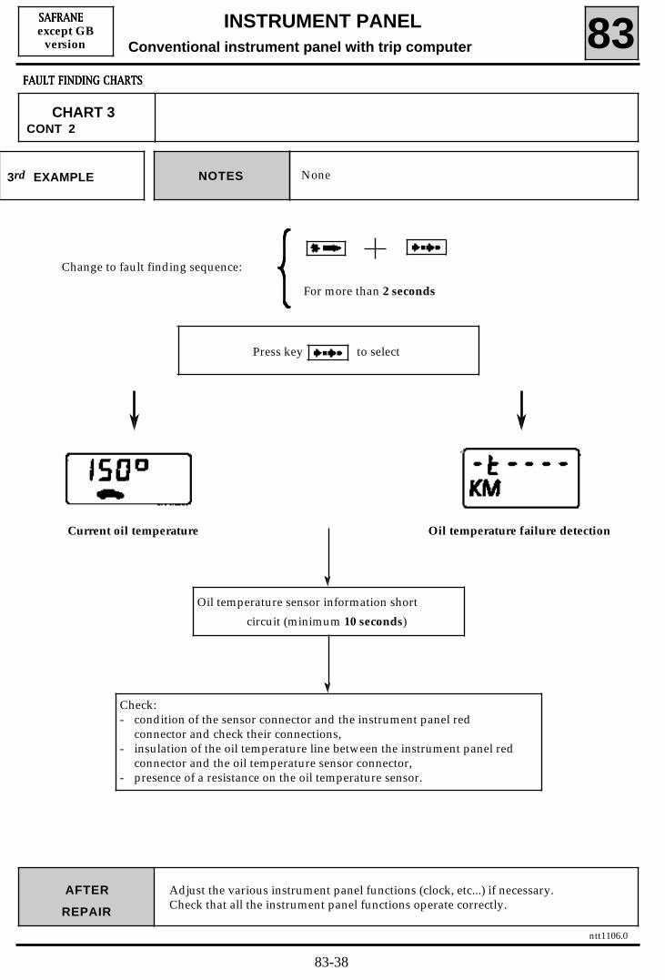
NoneNOTES3rd EXAMPLE
Change to fault finding sequence:
For more than 2 seconds
Press key to select
Current oil temperature Oil temperature failure detection
Oil temperature sensor information short
circuit (minimum 10 seconds)
Check:- condition of the sensor connector and the instrument panel red
connector and check their connections,- insulation of the oil temperature line between the instrument panel red
connector and the oil temperature sensor connector,- presence of a resistance on the oil temperature sensor.
Adjust the various instrument panel functions (clock, etc...) if necessary.Check that all the instrument panel functions operate correctly.
83-38

ntt1106.0
INSTRUMENT PANELConventional instrument panel with trip computer 83
SSSSAAAAFFFFRRRRAAAANNNNEEEEexcept GB
version
AFTER
REPAIR
FFFFAAAAUUUULLLLTTTT FFFFIIIINNNNDDDDIIIINNNNGGGG CCCCHHHHAAAARRRRTTTTSSSS
CHART 4 FLASHING OF RANGE
Instrument panel fault finding procedures are carried out with the ignition on.NOTES
NoneNOTES1st EXAMPLE
Change to fault finding sequence:
For more than 2 seconds
Press key to select
The value displayed (quantity of fuelremaining) should be the conversion of thegauge resistance.If the display is less than or equal to 5 litresthe fuel low signal is transmitted.
Intermittent fault
Gauge information fault for more than
100 seconds
Check:- condition of the fuel gauge connector and the instrument panel blue
connector and check their connections,- continuity of the fuel gauge throughout its range of operation (- 5 Ω/l).
Gauge failure detection
Adjust the various instrument panel functions (clock, etc...) if necessary.Check that all the instrument panel functions operate correctly.
83-39

ntt1106.0
INSTRUMENT PANEL
Conventional instrument panel with trip computer 83SSSSAAAAFFFFRRRRAAAANNNNEEEEexcept GB
version
AFTER
REPAIR
FFFFAAAAUUUULLLLTTTT FFFFIIIINNNNDDDDIIIINNNNGGGG CCCCHHHHAAAARRRRTTTTSSSS
CHART 4CONT
NoneNOTES2nd EXAMPLE
Change to fault finding sequence:
For more than 2 seconds
Press key to select
Current fuel level.Illumination of the fuel low warning lightand transmission of the voice synthesisermessage.
Gauge information cut-off
Check:- continuity of the fuel gauge (- 5 Ω/l),- continuity of the fuel lines between the instrument panel blue
connector and the gauge connector.
Gauge failure detection
Adjust the various instrument panel functions (clock, etc...) if necessary.Check that all the instrument panel functions operate correctly.
83-40

ntt1106.0
INSTRUMENT PANELConventional instrument panel with trip computer 83
SSSSAAAAFFFFRRRRAAAANNNNEEEEexcept GB
version
AFTER
REPAIR
FFFFAAAAUUUULLLLTTTT FFFFIIIINNNNDDDDIIIINNNNGGGG CCCCHHHHAAAARRRRTTTTSSSS
CHART 5 INCORRECT DISPLAY OF RANGE WITH NO
FLASHING OF DISPLAY
Instrument panel fault finding procedures are carried out with the ignition on.NOTES
Change to fault finding sequence:For more than 2 seconds
Press key to select
Maximum fuel level displayed when thetank is not full
Gauge information short circuit
Check:- resistance of the fuel gauge (- 5 Ω/l),- insulation of the gauge line between the instrument panel blue
connector and the gauge connector.
No gauge failure detection
Adjust the various instrument panel functions (clock, etc...) if necessary.Check that all the instrument panel functions operate correctly.
83-41

ntt1106.0
INSTRUMENT PANELConventional instrument panel with trip computer 83
SSSSAAAAFFFFRRRRAAAANNNNEEEEexcept GB
version
AFTER
REPAIR
FFFFAAAAUUUULLLLTTTT FFFFIIIINNNNDDDDIIIINNNNGGGG CCCCHHHHAAAARRRRTTTTSSSS
CHART 6 FLASHING OF SEVERAL FUNCTIONSNO CURRENT CONSUMPTION
Instrument panel fault finding procedures are carried out with the ignition on.NOTES
NoneNOTES1st EXAMPLE
Change to fault finding sequence:
For more than 2 seconds
Press key to select
Current flow in litres/hour
Intermittent failure
Flow information fault for more than 16 km.
Check the condition of the connector on theinjection computer and the instrument panelconnector and check their connections.
Flow information failure detection
Enginerunning
Adjust the various instrument panel functions (clock, etc...) if necessary.Check that all the instrument panel functions operate correctly.
83-42

ntt1106.0
INSTRUMENT PANELConventional instrument panel with trip computer 83
SSSSAAAAFFFFRRRRAAAANNNNEEEEexcept GB
version
AFTER
REPAIR
FFFFAAAAUUUULLLLTTTT FFFFIIIINNNNDDDDIIIINNNNGGGG CCCCHHHHAAAARRRRTTTTSSSS
CHART 6CONT
NoneNOTES2nd EXAMPLE
Change to fault finding sequence:
For more than 2 seconds
Press key to select
Current flow in litres/hour
Flow information cut-off
Check the continuity and insulation of the flowinformation line between the injection computerand the instrument panel red connector.
Flow information failure detection
Enginerunning
Adjust the various instrument panel functions (clock, etc...) if necessary.Check that all the instrument panel functions operate correctly.
83-43

ntt1106.0
INSTRUMENT PANELConventional instrument panel with trip computer 83
SSSSAAAAFFFFRRRRAAAANNNNEEEEexcept GB
version
AFTER
REPAIR
FFFFAAAAUUUULLLLTTTT FFFFIIIINNNNDDDDIIIINNNNGGGG CCCCHHHHAAAARRRRTTTTSSSS
CHART 7 INCORRECT OPERATION OF THEOIL PRESSURE LEVEL RECEIVER
Instrument panel fault finding procedures are carried out with the ignition on.NOTES
Change to fault finding sequence:
For more than 2 seconds
Press key to select
Oil pressure failure detection
Change the instrument panel
Oil pressure failure detection
Oil pressure sensordisconnected
Oil level sensordisconnected
If not If not
Using an ohmmeter, check:- continuity of the oil pressure sensor,- continuity and insulation of the oil pressure
line.
Using an ohmmeter, check:- resistance of the oil level sensor,- continuity and insulation of the oil level
line.
Check the movement of the needle (rest, minimumlevel, maximum level, maximum deviation).
POORGOOD
Adjust the various instrument panel functions (clock, etc...) if necessary.Check that all the instrument panel functions operate correctly.
83-44

ntt1106.0
INSTRUMENT PANELConventional instrument panel with trip computer 83
SSSSAAAAFFFFRRRRAAAANNNNEEEEexcept GB
version
AFTER
REPAIR
FFFFAAAAUUUULLLLTTTT FFFFIIIINNNNDDDDIIIINNNNGGGG CCCCHHHHAAAARRRRTTTTSSSS
CHART 8INCORRECT OPERATION OF OIL PRESSURE LEVEL RECEIVER IN
PRESSURE MODE(NEEDLE AT MAXIMUM, IGNITION ON)
Instrument panel fault finding procedures are carried out with the ignition on.NOTES
Change to fault finding sequence:
For more than 2 seconds
Press key
Check the movement of the needle (rest, minimumlevel, maximum level, maximum deviation).
GOOD
Change the instrument panel
No failure detection
Oil pressure line shortcircuit
Using an ohmmeter, check:- resistance of the oil pressure sensor,- insulation of the oil pressure line.
POOR
Adjust the various instrument panel functions (clock, etc...) if necessary.Check that all the instrument panel functions operate correctly.
83-45

no
ntt1106.0
INSTRUMENT PANELConventional instrument panel with trip computer 83
SSSSAAAAFFFFRRRRAAAANNNNEEEEexcept GB
version
AFTER
REPAIR
FFFFAAAAUUUULLLLTTTT FFFFIIIINNNNDDDDIIIINNNNGGGG CCCCHHHHAAAARRRRTTTTSSSS
CHART 9 NO MODE AND POSITION DISPLAY, FAULT WARNING LIGHT
ILLUMINATED OR FLASHING
Fault finding procedure for vehicles fitted with an automatic gearbox (BVA).NOTES
Check the potential of the automatic gearboxline in relation to the vehicle earth. Does the line potential = 0 volt ?
no
yes
no Change the instrument panel andreconnect the computer.
yes
Disconnect the automatic gearbox computerDoes the line potential = 0 volt ?
Reconnect the wiring.
yes
Disconnect the instrument panelDoes the line potential = 0 volt ?
noOperate the selector stopping in
each position.Is the display active?
yes no
Check the selector / multi-function switch assembly
Repair the wiring between the selector andthe automatic gearbox computer.
yes
Does the line potential = 12 volts ?
A
Adjust the various instrument panel functions (clock, etc...) if necessary.Check that all the instrument panel functions operate correctly.
Carry out the automatic gearboxcomputer fault finding procedure.
83-46

ntt1106.0
INSTRUMENT PANELConventional instrument panel with trip computer 83
SSSSAAAAFFFFRRRRAAAANNNNEEEEexcept GB
version
AFTER
REPAIR
FFFFAAAAUUUULLLLTTTT FFFFIIIINNNNDDDDIIIINNNNGGGG CCCCHHHHAAAARRRRTTTTSSSS
CHART 9CONT
A
no Repair the wiring.Check the continuity between the automatic
gearbox and the instrument panel.Is there continuity?
yes
no Carry out the automatic gearbox computerfault finding procedure.
Refit the old instrument panel.
yes
END
Change the instrument panel.Is the display active?
Adjust the various instrument panel functions (clock, etc...) if necessary.Check that all the instrument panel functions operate correctly.
83-47

ntt1106.0
INSTRUMENT PANELConventional instrument panel with trip computer 83
SSSSAAAAFFFFRRRRAAAANNNNEEEEexcept GB
version
AFTER
REPAIR
FFFFAAAAUUUULLLLTTTT FFFFIIIINNNNDDDDIIIINNNNGGGG CCCCHHHHAAAARRRRTTTTSSSS
CHART 10 NO DISPLAY (LEVER POSITION, PROGRAMME)FAULT WARNING LIGHT EXTINGUISHED
Fault finding procedure for vehicles fitted with an automatic gearbox (BVA).NOTES
yes Check the selector / multi-function switch assembly.
no
no
yes Repair the wiring.
yes
no
yes
no
yes
no
Disconnect and reconnect the battery.Is the display active?
Does the instrument panel have a tripcomputer?
Operate the selector stopping ineach position.
Is the display active?
Check the condition of the wiring betweeninstrument panel and automatic gearbox.
Is there an open circuit
no
no
Carry out the automatic gearboxcomputer fault finding procedure and
refit the old instrument panel.
Is there a short circuit to +ve?
yes
Enter and exit test mode.Is the display active?
yes
END
Change the instrument panel.Is the display active?
END
Adjust the various instrument panel functions (clock, etc...) if necessary.Check that all the instrument panel functions operate correctly.
83-48

ntt1106.0
INSTRUMENT PANELConventional instrument panel with trip computer 83
SSSSAAAAFFFFRRRRAAAANNNNEEEEexcept GB
version
AFTER
REPAIR
FFFFAAAAUUUULLLLTTTT FFFFIIIINNNNDDDDIIIINNNNGGGG CCCCHHHHAAAARRRRTTTTSSSS
CHART 11 DIGITS PARTIALLY DISPLAYED
NOTES Fault finding procedure for vehicles fitted with an automatic gearbox (BVA).
Are digits partially displayed?
yes
Operate the selector stopping ineach position.
Is the display active?
Change the instrument panel.
noyes
Check the selector / multi-functionswitch assembly.
Adjust the various instrument panel functions (clock, etc...) if necessary.Check that all the instrument panel functions operate correctly.
83-49

ntt1106.0
INSTRUMENT PANELConventional instrument panel with trip computer 83
SSSSAAAAFFFFRRRRAAAANNNNEEEEexcept GB
version
AFTER
REPAIR
FFFFAAAAUUUULLLLTTTT FFFFIIIINNNNDDDDIIIINNNNGGGG CCCCHHHHAAAARRRRTTTTSSSS
CHART 12 INCONSISTENCY BETWEEN SELECTOR POSITION ANDINFORMATION DISPLAYED ON INSTRUMENT PANEL
NOTES Fault finding procedure for vehicles fitted with an automatic gearbox (BVA).
This is not an instrumentpanel problem.
Inconsistency between selector position andinformation displayed on instrument panel.
Check theselector / multi-function switch assembly.
Is the display consistent?yes
no
Check the multi-function switch / automaticgearbox wiring.
Is the display consistent?no
yes
END
END
Carry out the automatic gearbox computerfault finding procedure.
Adjust the various instrument panel functions (clock, etc...) if necessary.Check that all the instrument panel functions operate correctly.
83-50

ntt1106.0
INSTRUMENT PANEL
Conventional instrument panel with trip computer 83SSSSAAAAFFFFRRRRAAAANNNNEEEE
GBversion
FFFFAAAAUUUULLLLTTTT FFFFIIIINNNNDDDDIIIINNNNGGGG ---- CCCCUUUUSSSSTTTTOOOOMMMMEEEERRRR CCCCOOOOMMMMPPPPLLLLAAAAIIIINNNNTTTTSSSS
Refer to the "Fault finding - Introduction" section before beginning this faultfinding procedure.
NOTES
CCCCHHHHAAAARRRRTTTT 1111
CCCCHHHHAAAARRRRTTTT 2222
CCCCHHHHAAAARRRRTTTT 3333
CCCCHHHHAAAARRRRTTTT 4444
CCCCHHHHAAAARRRRTTTT 5555
CCCCHHHHAAAARRRRTTTT 6666
CCCCHHHHAAAARRRRTTTT 7777
CCCCHHHHAAAARRRRTTTT 8888
CCCCHHHHAAAARRRRTTTT 9999
CCCCHHHHAAAARRRRTTTT 11110000
CCCCHHHHAAAARRRRTTTT 11111111
CCCCHHHHAAAARRRRTTTT 11112222
SAFRANE GB VERSION
SSSSPPPPEEEEEEEEDDDDOOOOMMMMEEEETTTTEEEERRRR DDDDOOOOEEEESSSS NNNNOOOOTTTT OOOOPPPPEEEERRRRAAAATTTTEEEE AAAANNNNDDDD IIIINNNNCCCCOOOORRRRRRRREEEECCCCTTTT TTTTRRRRIIIIPPPP CCCCOOOOMMMMPPPPUUUUTTTTEEEERRRR AAAANNNNDDDD TTTTOOOOTTTTAAAALLLLDDDDIIIISSSSTTTTAAAANNNNCCCCEEEE RRRREEEECCCCOOOORRRRDDDDEEEERRRR DDDDIIIISSSSPPPPLLLLAAAAYYYYSSSS
RRRREEEEVVVV CCCCOOOOUUUUNNNNTTTTEEEERRRR DDDDOOOOEEEESSSS NNNNOOOOTTTT OOOOPPPPEEEERRRRAAAATTTTEEEE
FFFFLLLLAAAASSSSHHHHIIIINNNNGGGG OOOOFFFF OOOOIIIILLLL DDDDRRRRAAAAIIIINNNN RRRRAAAANNNNGGGGEEEE
FFFFLLLLAAAASSSSHHHHIIIINNNNGGGG OOOOFFFF RRRRAAAANNNNGGGGEEEE
IIIINNNNCCCCOOOORRRRRRRREEEECCCCTTTT DDDDIIIISSSSPPPPLLLLAAAAYYYY OOOOFFFF RRRRAAAANNNNGGGGEEEE WWWWIIIITTTTHHHH NNNNOOOO FFFFLLLLAAAASSSSHHHHIIIINNNNGGGG OOOOFFFF DDDDIIIISSSSPPPPLLLLAAAAYYYY
FFFFLLLLAAAASSSSHHHHIIIINNNNGGGG OOOOFFFF SSSSEEEEVVVVEEEERRRRAAAALLLL FFFFUUUUNNNNCCCCTTTTIIIIOOOONNNNSSSS
IIIINNNNCCCCOOOORRRRRRRREEEECCCCTTTT OOOOPPPPEEEERRRRAAAATTTTIIIIOOOONNNN OOOOFFFF OOOOIIIILLLL PPPPRRRREEEESSSSSSSSUUUURRRREEEE LLLLEEEEVVVVEEEELLLL RRRREEEECCCCEEEEIIIIVVVVEEEERRRR
IIIINNNNCCCCOOOORRRRRRRREEEECCCCTTTT OOOOPPPPEEEERRRRAAAATTTTIIIIOOOONNNN OOOOFFFF OOOOIIIILLLL PPPPRRRREEEESSSSSSSSUUUURRRREEEE LLLLEEEEVVVVEEEELLLL RRRREEEECCCCEEEEIIIIVVVVEEEERRRR IIIINNNN PPPPRRRREEEESSSSSSSSUUUURRRREEEE MMMMOOOODDDDEEEE ((((NNNNEEEEEEEEDDDDLLLLEEEEAAAATTTT MMMMAAAAXXXXIIIIMMMMUUUUMMMM,,,, IIIIGGGGNNNNIIIITTTTIIIIOOOONNNN OOOONNNN))))
For vehicles fitted with an automatic gearbox:
NNNNOOOO MMMMOOOODDDDEEEE AAAANNNNDDDD PPPPOOOOSSSSIIIITTTTIIIIOOOONNNN DDDDIIIISSSSPPPPLLLLAAAAYYYYFFFFAAAAUUUULLLLTTTT WWWWAAAARRRRNNNNIIIINNNNGGGG LLLLIIIIGGGGHHHHTTTT IIIILLLLLLLLUUUUMMMMIIIINNNNAAAATTTTEEEEDDDD OOOORRRR FFFFLLLLAAAASSSSHHHHIIIINNNNGGGG
NNNNOOOO DDDDIIIISSSSPPPPLLLLAAAAYYYY ((((LLLLEEEEVVVVEEEERRRR PPPPOOOOSSSSIIIITTTTIIIIOOOONNNN,,,, PPPPRRRROOOOGGGGRRRRAAAAMMMMMMMMEEEE))))FFFFAAAAUUUULLLLTTTT WWWWAAAARRRRNNNNIIIINNNNGGGG LLLLIIIIGGGGHHHHTTTT EEEEXXXXTTTTIIIINNNNGGGGUUUUIIIISSSSHHHHEEEEDDDD
DDDDIIIIGGGGIIIITTTTSSSS PPPPAAAARRRRTTTTIIIIAAAALLLLLLLLYYYY DDDDIIIISSSSPPPPLLLLAAAAYYYYEEEEDDDD
IIIINNNNCCCCOOOONNNNSSSSIIIISSSSTTTTEEEENNNNCCCCYYYY BBBBEEEETTTTWWWWEEEEEEEENNNN SSSSEEEELLLLEEEECCCCTTTTOOOORRRR PPPPOOOOSSSSIIIITTTTIIIIOOOONNNN AAAANNNNDDDD IIIINNNNFFFFOOOORRRRMMMMAAAATTTTIIIIOOOONNNN DDDDIIIISSSSPPPPLLLLAAAAYYYYEEEEDDDD OOOONNNNIIIINNNNSSSSTTTTRRRRUUUUMMMMEEEENNNNTTTT PPPPAAAANNNNEEEELLLL
83-51

ntt1106.0
INSTRUMENT PANELConventional instrument panel with trip computer 83
SSSSAAAAFFFFRRRRAAAANNNNEEEEGB
version
AFTER
REPAIR
FFFFAAAAUUUULLLLTTTT FFFFIIIINNNNDDDDIIIINNNNGGGG CCCCHHHHAAAARRRRTTTTSSSS
CHART 1SPEEDOMETER DOES NOT OPERATE AND INCORRECT TRIPCOMPUTER AND TOTAL DISTANCE RECORDER DISPLAYS
Instrument panel fault finding procedures are carried out with the ignition on.NOTES
GOOD
Change to fault finding sequence:
For more than 2 seconds
Check the movement of the needle to 40 at 40 mph/h
POOR
Change the instrument panel
GOOD
GOOD
RepairPOOR
POOR
Check that the instrument panel connector and itspins are in good condition.POORRepair
GOOD
A
Check:- connection of the sensor cable to the gearbox,- correct connection of the connector on the
sensor,- + after ignition supply on track A and earth on
track C on the sensor connector.
Check:- the continuity and insulation of the wiring
between the speed sensor and the instrumentpanel.
Adjust the various instrument panel functions (clock, etc...) if necessary.Check that all the instrument panel functions operate correctly.
83-52

ntt1106.0
INSTRUMENT PANELConventional instrument panel with trip computer 83
SSSSAAAAFFFFRRRRAAAANNNNEEEEGB
version
AFTER
REPAIR
FFFFAAAAUUUULLLLTTTT FFFFIIIINNNNDDDDIIIINNNNGGGG CCCCHHHHAAAARRRRTTTTSSSS
CHART 1CONT
GOOD
Press key
to change to the second fault finding phase
Press key to select
Current speed in miles/hour (vehicle moving)
If O
Change thespeed sensor.
A
Adjust the various instrument panel functions (clock, etc...) if necessary.Check that all the instrument panel functions operate correctly.
83-53

ntt1106.0
INSTRUMENT PANELConventional instrument panel with trip computer 83
SSSSAAAAFFFFRRRRAAAANNNNEEEEGB
version
AFTER
REPAIR
FFFFAAAAUUUULLLLTTTT FFFFIIIINNNNDDDDIIIINNNNGGGG CCCCHHHHAAAARRRRTTTTSSSS
CHART 2 REV COUNTER DOES NOT OPERATE
Instrument panel fault finding procedures are carried out with the ignition on.Check the condition of the engine earth.NOTES
Change to fault finding sequence:
For more than 2 seconds
Check the movement of the needle to 1 000 at 1 000 rpm
POOR
Change the instrument panel
GOOD
GOOD
Change the injection computer or thealternator depending on the engine.
Check the continuity and insulation ofthe rev counter information wirebetween the injection computer andthe instrument panel or between thealternator and the instrument paneldepending on the engine installed inthe vehicle.
Adjust the various instrument panel functions (clock, etc...) if necessary.Check that all the instrument panel functions operate correctly.
83-54

ntt1106.0
INSTRUMENT PANELConventional instrument panel with trip computer 83
SSSSAAAAFFFFRRRRAAAANNNNEEEEGB
version
AFTER
REPAIR
FFFFAAAAUUUULLLLTTTT FFFFIIIINNNNDDDDIIIINNNNGGGG CCCCHHHHAAAARRRRTTTTSSSS
CHART 3 FLASHING OF THE OIL DRAIN RANGE
Instrument panel fault finding procedures are carried out with the ignition on.NOTES
NoneNOTES1st EXAMPLE
Change to fault finding sequence:
For more than 2 seconds
Press key to select
Current oil temperature Oil temperature failure detection
Check:- condition of the sensor connector and the
instrument panel red connector and checktheir connections.
Intermittent fault
Oil temperature sensor information fault formore than 10 seconds
Adjust the various instrument panel functions (clock, etc...) if necessary.Check that all the instrument panel functions operate correctly.
83-55

ntt1106.0
INSTRUMENT PANELConventional instrument panel with trip computer 83
SSSSAAAAFFFFRRRRAAAANNNNEEEEGB
version
AFTER
REPAIR
FFFFAAAAUUUULLLLTTTT FFFFIIIINNNNDDDDIIIINNNNGGGG CCCCHHHHAAAARRRRTTTTSSSS
CHART 3CONT 1
NoneNOTES2nd EXAMPLE
Change to fault finding sequence:
For more than 2 seconds
Press key to select
Current oil temperature Oil temperature failure detection
Oil temperature sensor information cut-off
(minimum 10 seconds).
Check:- condition of the sensor connector and the instrument panel red
connector and check their connections,- continuity of the oil temperature lines between the oil temperature
sensor connector and the instrument panel red connector.- continuity of the oil temperature sensor.
Adjust the various instrument panel functions (clock, etc...) if necessary.Check that all the instrument panel functions operate correctly.
83-56

ntt1106.0
INSTRUMENT PANELConventional instrument panel with trip computer 83
SSSSAAAAFFFFRRRRAAAANNNNEEEEGB
version
AFTER
REPAIR
FFFFAAAAUUUULLLLTTTT FFFFIIIINNNNDDDDIIIINNNNGGGG CCCCHHHHAAAARRRRTTTTSSSS
CHART 3CONT 2
NoneNOTES3rd EXAMPLE
Change to fault finding sequence:
For more than 2 seconds
Press key to select
Current oil temperature Oil temperature failure detection
Oil temperature sensor information short
circuit (minimum 10 seconds)
Check:- condition of the sensor connector and the instrument panel red
connector and check their connections,- insulation of the oil temperature line between the instrument panel red
connector and the oil temperature sensor connector,- presence of a resistance on the oil temperature sensor.
Adjust the various instrument panel functions (clock, etc...) if necessary.Check that all the instrument panel functions operate correctly.
83-57

ntt1106.0
INSTRUMENT PANEL
Conventional instrument panel with trip computer 83SSSSAAAAFFFFRRRRAAAANNNNEEEE
GBversion
AFTER
REPAIR
FFFFAAAAUUUULLLLTTTT FFFFIIIINNNNDDDDIIIINNNNGGGG CCCCHHHHAAAARRRRTTTTSSSS
CHART 4 FLASHING OF RANGE
NOTES
NoneNOTES1st EXAMPLE
Change to fault finding sequence:
For more than 2 seconds
Press key to select
Intermittent fault
Gauge information fault for more than
100 seconds
Gauge failure detectionThe value displayed (quantity of fuelremaining) should be the conversion of thegauge resistance.If the display is less than or equal to1.1 gallons the fuel low signal is transmitted.
Check:- condition of the fuel gauge connector and the instrument panel blue
connector and check their connections,- continuity of the fuel gauge throughout its range of operation (- 5 Ω/l).
Adjust the various instrument panel functions (clock, etc...) if necessary.Check that all the instrument panel functions operate correctly.
83-58

ntt1106.0
INSTRUMENT PANELConventional instrument panel with trip computer 83
SSSSAAAAFFFFRRRRAAAANNNNEEEEGB
version
AFTER
REPAIR
FFFFAAAAUUUULLLLTTTT FFFFIIIINNNNDDDDIIIINNNNGGGG CCCCHHHHAAAARRRRTTTTSSSS
CHART 4CONT
NoneNOTES2nd EXAMPLE
Change to fault finding sequence:
For more than 2 seconds
Press key to select
Gauge information cut-off
Gauge failure detectionCurrent fuel level.Illumination of the fuel low warning lightand transmission of the voice synthesisermessage.
Check:- continuity of the fuel gauge (- 22.5 Ω/G),- continuity of the fuel lines between the instrument panel blue
connector and the gauge connector.
Adjust the various instrument panel functions (clock, etc...) if necessary.Check that all the instrument panel functions operate correctly.
83-59

ntt1106.0
INSTRUMENT PANELConventional instrument panel with trip computer 83
SSSSAAAAFFFFRRRRAAAANNNNEEEEGB
version
AFTER
REPAIR
FFFFAAAAUUUULLLLTTTT FFFFIIIINNNNDDDDIIIINNNNGGGG CCCCHHHHAAAARRRRTTTTSSSS
CHART 5 INCORRECT RANGE DISPLAY WITH NO FLASHINGOF DISPLAY
Instrument panel fault finding procedures are carried out with the ignition on.NOTES
Change to fault finding sequence:
For more than 2 seconds
Press key to select
Maximum fuel level displayed when thetank is not full
Gauge information short circuit
No gauge failure detection
Check:- resistance of the fuel gauge (- 22.5 Ω/G),- insulation of the gauge line between the instrument panel blue
connector and the gauge connector.
Adjust the various instrument panel functions (clock, etc...) if necessary.Check that all the instrument panel functions operate correctly.
83-60

ntt1106.0
INSTRUMENT PANELConventional instrument panel with trip computer 83
SSSSAAAAFFFFRRRRAAAANNNNEEEEGB
version
AFTER
REPAIR
FFFFAAAAUUUULLLLTTTT FFFFIIIINNNNDDDDIIIINNNNGGGG CCCCHHHHAAAARRRRTTTTSSSS
CHART 6 FLASHING OF SEVERAL FUNCTIONS
Instrument panel fault finding procedures are carried out with the ignition on.NOTES
NoneNOTES1st EXAMPLE
Change to fault finding sequence:
For more than 2 seconds
Press key to select
Current flow in gallons/hour
Check the condition of the connector on theinjection computer and the instrument panelconnector and check their connections.
Flow information failure detection
Enginerunning
Intermittent failureFlow information fault for more than
10 miles.
Adjust the various instrument panel functions (clock, etc...) if necessary.Check that all the instrument panel functions operate correctly.
83-61

ntt1106.0
INSTRUMENT PANELConventional instrument panel with trip computer 83
SSSSAAAAFFFFRRRRAAAANNNNEEEEGB
version
AFTER
REPAIR
FFFFAAAAUUUULLLLTTTT FFFFIIIINNNNDDDDIIIINNNNGGGG CCCCHHHHAAAARRRRTTTTSSSS
CHART 6CONT
NoneNOTES2nd EXAMPLE
Change to fault finding sequence:
For more than 2 seconds
Press key to select
Current flow in gallons/hour
Flow information cut-off
Check the continuity and insulation of the flowinformation line between the injection computerand the instrument panel red connector.
Flow information failure detection
Enginerunning
Adjust the various instrument panel functions (clock, etc...) if necessary.Check that all the instrument panel functions operate correctly.
83-62

ntt1106.0
INSTRUMENT PANELConventional instrument panel with trip computer 83
SSSSAAAAFFFFRRRRAAAANNNNEEEEGB
version
AFTER
REPAIR
FFFFAAAAUUUULLLLTTTT FFFFIIIINNNNDDDDIIIINNNNGGGG CCCCHHHHAAAARRRRTTTTSSSS
CHART 7 INCORRECT OPERATION OFOIL PRESSURE LEVEL RECEIVER
Instrument panel fault finding procedures are carried out with the ignition on.NOTES
Change to fault finding sequence:
For more than 2 seconds
Press key to select
Oil level failure detection
GOOD
Change the instrument panel
Oil pressure failure detection
Oil pressure sensordisconnected
Oil level sensordisconnected
If not If not
Check the movement of the needle (rest, minimumlevel, maximum level, maximum deviation).
POOR
Using an ohmmeter, check:- continuity of the oil pressure sensor,- continuity and insulation of the oil pressure
line.
Using an ohmmeter, check:- resistance of the oil level sensor,- continuity and insulation of the oil level
line.
Adjust the various instrument panel functions (clock, etc...) if necessary.Check that all the instrument panel functions operate correctly.
83-63

ntt1106.0
INSTRUMENT PANELConventional instrument panel with trip computer 83
SSSSAAAAFFFFRRRRAAAANNNNEEEEGB
version
AFTER
REPAIR
FFFFAAAAUUUULLLLTTTT FFFFIIIINNNNDDDDIIIINNNNGGGG CCCCHHHHAAAARRRRTTTTSSSS
CHART 8
Instrument panel fault finding procedures are carried out with the ignition on.NOTES
Change to fault finding sequence:
For more than 2 seconds
Press key
Check the movement of the needle (rest, minimumlevel, maximum level, maximum deviation).
GOOD
Change the instrument panel
Oil pressure line shortcircuit
No failure detection
INCORRECT OPERATION OF OIL PRESSURE LEVEL RECEIVER INPRESSURE MODE
(NEEDLE AT MAXIMUM, IGNITION ON)
POOR
Using an ohmmeter, check:- resistance of the oil pressure sensor,- insulation of the oil pressure line.
Adjust the various instrument panel functions (clock, etc...) if necessary.Check that all the instrument panel functions operate correctly.
83-64

no
ntt1106.0
INSTRUMENT PANELConventional instrument panel with trip computer 83
SSSSAAAAFFFFRRRRAAAANNNNEEEEGB
version
AFTER
REPAIR
FFFFAAAAUUUULLLLTTTT FFFFIIIINNNNDDDDIIIINNNNGGGG CCCCHHHHAAAARRRRTTTTSSSS
CHART 9 NO MODE AND POSITION DISPLAY, WARNING LIGHT
ILLUMINATED OR FLASHING
Fault finding procedure for vehicles fitted with an automatic gearbox (BVA).NOTES
no Carry out the automatic gearboxcomputer fault finding procedure.
yes
no Change the instrument panel andreconnect the computer.
yes
Reconnect the wiring.
yes
noOperate the selector stopping in
each position.Is the display active?
yes no
Check the selector / multi-function switch assembly
Repair the wiring between the selector andthe automatic gearbox computer.
yes
Does the line potential = 12 volts ?
A
Check the potential of the automatic gearboxline in relation to the vehicle earth. Does the line potential = 0 volt ?
Disconnect the automatic gearbox computerDoes the line potential = 0 volt ?
Disconnect the instrument panelDoes the line potential = 0 volt ?
Adjust the various instrument panel functions (clock, etc...) if necessary.Check that all the instrument panel functions operate correctly.
83-65

ntt1106.0
INSTRUMENT PANELConventional instrument panel with trip computer 83
SSSSAAAAFFFFRRRRAAAANNNNEEEEGB
version
AFTER
REPAIR
FFFFAAAAUUUULLLLTTTT FFFFIIIINNNNDDDDIIIINNNNGGGG CCCCHHHHAAAARRRRTTTTSSSS
CHART 9CONT
A
no Repair the wiring.
yes
no Carry out the automatic gearbox computerfault finding procedure.
Refit the old instrument panel.
yes
END
Check the continuity between the automaticgearbox and the instrument panel.
Is there continuity?
Change the instrument panel.Is the display active?
Adjust the various instrument panel functions (clock, etc...) if necessary.Check that all the instrument panel functions operate correctly.
83-66

ntt1106.0
INSTRUMENT PANELConventional instrument panel with trip computer 83
SSSSAAAAFFFFRRRRAAAANNNNEEEEGB
version
AFTER
REPAIR
FFFFAAAAUUUULLLLTTTT FFFFIIIINNNNDDDDIIIINNNNGGGG CCCCHHHHAAAARRRRTTTTSSSS
CHART 10 NO DISPLAY (LEVER POSITION, PROGRAMME)FAULT WARNING LIGHT EXTINGUISHED
Fault finding procedure for vehicles fitted with an automatic gearbox (BVA).NOTES
yes
no
no
yes Repair the wiring.
yes
no
yes END
no
yes
no
no
no
Is there a short circuit to +ve?
yes yes
END
Check the selector / multi-function switch assembly.
Operate the selector stopping ineach position.
Is the display active?
Carry out the automatic gearboxcomputer fault finding procedure and
refit the old instrument panel.
Change the instrument panel.Is the display active?
Enter and exit test mode.Is the display active?
Does the instrument panel have a tripcomputer?
Disconnect and reconnect the battery.Is the display active?
Check the condition of the wiring betweeninstrument panel and automatic gearbox.
Is there an open circuit
Adjust the various instrument panel functions (clock, etc...) if necessary.Check that all the instrument panel functions operate correctly.
83-67

ntt1106.0
INSTRUMENT PANELConventional instrument panel with trip computer 83
SSSSAAAAFFFFRRRRAAAANNNNEEEEGB
version
AFTER
REPAIR
FFFFAAAAUUUULLLLTTTT FFFFIIIINNNNDDDDIIIINNNNGGGG CCCCHHHHAAAARRRRTTTTSSSS
CHART 11 DIGITS PARTIALLY DISPLAYED
NOTES Fault finding procedure for vehicles fitted with an automatic gearbox (BVA).
Are digits partially displayed?
yes
Change the instrument panel.
noyes
Adjust the various instrument panel functions (clock, etc...) if necessary.Check that all the instrument panel functions operate correctly.
Check the selector / multi-functionswitch assembly.
Operate the selector stopping ineach position.
Is the display active?
83-68

ntt1106.0
INSTRUMENT PANELConventional instrument panel with trip computer 83
SSSSAAAAFFFFRRRRAAAANNNNEEEEGB
version
AFTER
REPAIR
FFFFAAAAUUUULLLLTTTT FFFFIIIINNNNDDDDIIIINNNNGGGG CCCCHHHHAAAARRRRTTTTSSSS
CHART 12 INCONSISTENCY BETWEEN SELECTOR POSITION ANDINFORMATION DISPLAYED ON INSTRUMENT PANEL
NOTES Fault finding procedure for vehicles fitted with an automatic gearbox (BVA).
This is not an instrumentpanel problem.
Inconsistency between selector position andinformation displayed on instrument panel.
yes
no
no Carry out the automatic gearbox computerfault finding procedure.
yes
END
Adjust the various instrument panel functions (clock, etc...) if necessary.Check that all the instrument panel functions operate correctly.
END
Check the multi-function switch / automaticgearbox wiring.
Is the display consistent?
Check theselector / multi-function switch assembly.
Is the display consistent?
83-69

RT
ntt1106.0
INSTRUMENT PANELConventional instrument panel with trip computer 83LLLLAAAAGGGGUUUUNNNNAAAA
FFFFAAAAUUUULLLLTTTT FFFFIIIINNNNDDDDIIIINNNNGGGG ----CCCCUUUUSSSSTTTTOOOOMMMMEEEERRRR CCCCOOOOMMMMPPPPLLLLAAAAIIIINNNNTTTTSSSS
Refer to the "Fault finding - Introduction" section before starting the fault findingprocedure.
NOTES
OOOOIIIILLLL DDDDRRRRAAAAIIIINNNN RRRRAAAANNNNGGGGEEEE DDDDEEEECCCCRRRREEEEAAAASSSSEEEE CCCCOOOORRRRRRRREEEESSSSPPPPOOOONNNNDDDDIIIINNNNGGGG EEEEXXXXAAAACCCCTTTTLLLLYYYY TTTTOOOO TTTTHHHHEEEE DDDDIIIISSSSTTTTAAAANNNNCCCCEEEE CCCCOOOOVVVVEEEERRRREEEEDDDD****
FFFFLLLLAAAASSSSHHHHIIIINNNNGGGG DDDDAAAASSSSHHHHEEEESSSS SSSSOOOOMMMMEEEETTTTIIIIMMMMEEEESSSS DDDDIIIISSSSPPPPLLLLAAAAYYYYEEEEDDDD IIIINNNN PPPPLLLLAAAACCCCEEEE OOOOFFFF RRRRAAAANNNNGGGGEEEE****
FFFFLLLLAAAASSSSHHHHIIIINNNNGGGG DDDDAAAASSSSHHHHEEEESSSS DDDDIIIISSSSPPPPLLLLAAAAYYYYEEEEDDDD IIIINNNN PPPPLLLLAAAACCCCEEEE OOOOFFFF RRRRAAAANNNNGGGGEEEE****
IIIINNNNCCCCOOOORRRRRRRREEEECCCCTTTT RRRRAAAANNNNGGGGEEEE DDDDIIIISSSSPPPPLLLLAAAAYYYY****
SSSSEEEEVVVVEEEERRRRAAAALLLL FFFFUUUUNNNNCCCCTTTTIIIIOOOONNNNSSSS RRRREEEEPPPPLLLLAAAACCCCEEEEDDDD BBBBYYYY FFFFLLLLAAAASSSSHHHHIIIINNNNGGGG DDDDAAAASSSSHHHHEEEESSSS
IIIINNNNCCCCOOOORRRRRRRREEEECCCCTTTT OOOOPPPPEEEERRRRAAAATTTTIIIIOOOONNNN OOOOFFFF OOOOIIIILLLL LLLLEEEEVVVVEEEELLLL RRRREEEECCCCEEEEIIIIVVVVEEEERRRR
CCCCOOOOOOOOLLLLAAAANNNNTTTT TTTTEEEEMMMMPPPPEEEERRRRAAAATTTTUUUURRRREEEE IIIINNNNDDDDIIIICCCCAAAATTTTOOOORRRR NNNNEEEEEEEEDDDDLLLLEEEE RRRREEEEMMMMAAAAIIIINNNNSSSS AAAATTTT MMMMAAAAXXXXIIIIMMMMUUUUMMMM ((((IIIIGGGGNNNNIIIITTTTIIIIOOOONNNN OOOONNNN))))EEEENNNNGGGGIIIINNNNEEEE CCCCOOOOLLLLDDDD
IIIINNNNCCCCOOOORRRRRRRREEEECCCCTTTT DDDDIIIISSSSPPPPLLLLAAAAYYYY OOOOFFFF OOOOIIIILLLL LLLLEEEEVVVVEEEELLLL BBBBUUUUTTTT TTTTOOOOTTTTAAAALLLL DDDDIIIISSSSTTTTAAAANNNNCCCCEEEE DDDDIIIISSSSPPPPLLLLAAAAYYYYEEEEDDDD
NNNNEEEEIIIITTTTHHHHEEEERRRR OOOOIIIILLLL LLLLEEEEVVVVEEEELLLL NNNNOOOORRRR TTTTOOOOTTTTAAAALLLL DDDDIIIISSSSTTTTAAAANNNNCCCCEEEE DDDDIIIISSSSPPPPLLLLAAAAYYYYEEEEDDDD
NNNNOOOO DDDDIIIISSSSPPPPLLLLAAAAYYYY OOOORRRR PPPPAAAARRRRTTTTIIIIAAAALLLL DDDDIIIISSSSPPPPLLLLAAAAYYYY OOOOFFFF TTTTRRRRIIIIPPPP CCCCOOOOMMMMPPPPUUUUTTTTEEEERRRR
TTTTRRRRIIIIPPPP CCCCOOOOMMMMPPPPUUUUTTTTEEEERRRR DDDDIIIISSSSPPPPLLLLAAAAYYYY WWWWIIIITTTTHHHH PPPPAAAARRRRTTTTIIIIAAAALLLL LLLLOOOOSSSSSSSS OOOOFFFF SSSSEEEEGGGGMMMMEEEENNNNTTTTSSSS OOOORRRR SSSSEEEEGGGGMMMMEEEENNNNTTTTSSSS AAAATTTT HHHHAAAALLLLFFFFDDDDEEEENNNNSSSSIIIITTTTYYYY
For vehicles fitted with an automatic gearbox:
NNNNOOOO MMMMOOOODDDDEEEE AAAANNNNDDDD PPPPOOOOSSSSIIIITTTTIIIIOOOONNNN DDDDIIIISSSSPPPPLLLLAAAAYYYYFFFFAAAAUUUULLLLTTTT WWWWAAAARRRRNNNNIIIINNNNGGGG LLLLIIIIGGGGHHHHTTTT IIIILLLLLLLLUUUUMMMMIIIINNNNAAAATTTTEEEEDDDD OOOORRRR FFFFLLLLAAAASSSSHHHHIIIINNNNGGGG
NNNNOOOO DDDDIIIISSSSPPPPLLLLAAAAYYYY ((((LLLLEEEEVVVVEEEERRRR PPPPOOOOSSSSIIIITTTTIIIIOOOONNNN,,,, PPPPRRRROOOOGGGGRRRRAAAAMMMMMMMMEEEE))))FFFFAAAAUUUULLLLTTTT WWWWAAAARRRRNNNNIIIINNNNGGGG LLLLIIIIGGGGHHHHTTTT EEEEXXXXTTTTIIIINNNNGGGGUUUUIIIISSSSHHHHEEEEDDDD
DDDDIIIIGGGGIIIITTTTSSSS PPPPAAAARRRRTTTTIIIIAAAALLLLLLLLYYYY DDDDIIIISSSSPPPPLLLLAAAAYYYYEEEEDDDD
IIIINNNNCCCCOOOONNNNSSSSIIIISSSSTTTTEEEENNNNCCCCYYYY BBBBEEEETTTTWWWWEEEEEEEENNNN SSSSEEEELLLLEEEECCCCTTTTOOOORRRR PPPPOOOOSSSSIIIITTTTIIIIOOOONNNN AAAANNNNDDDD IIIINNNNFFFFOOOORRRRMMMMAAAATTTTIIIIOOOONNNN DDDDIIIISSSSPPPPLLLLAAAAYYYYEEEEDDDD OOOONNNNIIIINNNNSSSSTTTTRRRRUUUUMMMMEEEENNNNTTTT PPPPAAAANNNNEEEELLLL
CCCCHHHHAAAARRRRTTTT 1111
CCCCHHHHAAAARRRRTTTT 2222
CCCCHHHHAAAARRRRTTTT 3333
CCCCHHHHAAAARRRRTTTT 4444
CCCCHHHHAAAARRRRTTTT 5555
CCCCHHHHAAAARRRRTTTT 6666
CCCCHHHHAAAARRRRTTTT 7777
CCCCHHHHAAAARRRRTTTT 8888
CCCCHHHHAAAARRRRTTTT 9999
CCCCHHHHAAAARRRRTTTT 11110000
CCCCHHHHAAAARRRRTTTT 11111111
CCCCHHHHAAAARRRRTTTT 11112222
CCCCHHHHAAAARRRRTTTT 11113333
CCCCHHHHAAAARRRRTTTT 11114444
CCCCHHHHAAAARRRRTTTT 11115555
* : if vehicle manufactured before 30/09/96
83-70

ntt1106.0
INSTRUMENT PANELConventional instrument panel with trip computer 83LLLLAAAAGGGGUUUUNNNNAAAA
Adjust the various instrument panel functions (clock, etc, ...) if necessary.Check that all the instrument panel functions operate correctly.
AFTER
REPAIR
FFFFAAAAUUUULLLLTTTT FFFFIIIINNNNDDDDIIIINNNNGGGG CCCCHHHHAAAARRRRTTTTSSSS
CHART 1 OIL DRAIN RANGE DECREASE CORRESPONDING EXACTLY TO THEDISTANCE COVERED
This fault finding procedure only applies to vehicles manufactured before 30/09/97.Instrument panel fault finding procedures are carried out with the ignition on.NOTES
NoneNOTES1st EXAMPLE
Change to fault finding sequence
Press key to select the display required.
Simultaneous pressing of the trip computer advance key at theend of the wiper stalk and the zero reset / reset button for more than2 seconds.
and
Current oil temperature Oil temperature failure detection
Intermittent failure.Oil temperature sensor information fault for more
than 100 seconds.
Check the condition of the sensor connectorand the instrument panel red connector
and check their connections.
83-71

Press key to select the display required.
Simultaneous pressing for more than 2 seconds of the trip computeradvance key at the end of the wiper stalk and the zero reset /reset button.
ntt1106.0
INSTRUMENT PANELConventional instrument panel with trip computer 83LLLLAAAAGGGGUUUUNNNNAAAA
AFTER
REPAIR
FFFFAAAAUUUULLLLTTTT FFFFIIIINNNNDDDDIIIINNNNGGGG CCCCHHHHAAAARRRRTTTTSSSS
CHART 1CONT 1
NoneNOTES2nd EXAMPLE
Change to fault finding sequence
and
Current oil temperature Oil temperature failure detection
Oil temperature sensor informationcut-off or short circuit
for more than 100 seconds.
poor Repair.
poor Change the oiltemperature sensor.
Check the condition of the oil temperature sensorconnector and the instrument panel red
connector and check their connections.
good
A
Check the continuity of the oiltemperature sensor and the presence
of a resistance of between 40 Ω and 2 kΩ
good
Adjust the various instrument panel functions (clock, etc, ...) if necessary.Check that all the instrument panel functions operate correctly.
83-72

ntt1106.0
INSTRUMENT PANELConventional instrument panel with trip computer 83LLLLAAAAGGGGUUUUNNNNAAAA
AFTER
REPAIR
FFFFAAAAUUUULLLLTTTT FFFFIIIINNNNDDDDIIIINNNNGGGG CCCCHHHHAAAARRRRTTTTSSSS
CHART 1CONT 2
A
good poor
Change theinstrument panel.
Repair.
Check the continuity and insulation of the oiltemperature information lines between theinstrument panel red connector and the oiltemperature sensor connector.
Adjust the various instrument panel functions (clock, etc, ...) if necessary.Check that all the instrument panel functions operate correctly.New instrument panels must be configured (see Workshop Repair Manual MR 307and Technical Note NT 2632A).
83-73

Simultaneous pressing for more than 2 seconds of the trip computeradvance key at the end of the wiper stalk and the zero reset /reset button.
ntt1106.0
INSTRUMENT PANELConventional instrument panel with trip computer 83LLLLAAAAGGGGUUUUNNNNAAAA
AFTER
REPAIR
FFFFAAAAUUUULLLLTTTT FFFFIIIINNNNDDDDIIIINNNNGGGG CCCCHHHHAAAARRRRTTTTSSSS
CHART 2 FLASHING DASHES SOMETIMES DISPLAYED IN PLACEOF RANGE
NOTES
Change to fault finding sequence
Press key to selectthe display required.
and
Gauge failure detection.
Check :
- The condition of the fuel gauge connector and theinstrument panel connector and check theirconnections.
- The continuity of the fuel gauge throughout itsoperating range (- 5 Ω / litre approximately).
The value displayed (quantity of fuelremaining) should be the conversion of thegauge resistance.If the display is less than or equal to 6 litres,the fuel low signal is transmitted.
Intermittent fault.Gauge information fault for more than
100 consecutive seconds.
Adjust the various instrument panel functions (clock, etc, ...) if necessary.Check that all the instrument panel functions operate correctly.
This fault finding procedure only applies to vehicles manufactured before 30/09/97.Instrument panel fault finding procedures are carried out with the ignition on.
83-74

Simultaneous pressing for more than 2 seconds of the trip computeradvance key at the end of the wiper stalk and the zero reset /reset button.
ntt1106.0
INSTRUMENT PANELConventional instrument panel with trip computer 83LLLLAAAAGGGGUUUUNNNNAAAA
AFTER
REPAIR
FFFFAAAAUUUULLLLTTTT FFFFIIIINNNNDDDDIIIINNNNGGGG CCCCHHHHAAAARRRRTTTTSSSS
CHART 3 FLASHING DASHES DISPLAYED IN PLACE OF RANGE
NOTES
Change to fault finding sequence
Press key to select the display required.
and
Gauge failure detection.
poor
A
Level of fuel remaining in the tank.Illumination of the fuel low warning lightand transmission of the voice synthesisermessage.
poor Change the gauge.
Gauge information cut-off.
Check the continuity of the fuel gauge.
Check the condition of the instrument panelred connector and the gauge connector
and check their connections.
Adjust the various instrument panel functions (clock, etc, ...) if necessary.Check that all the instrument panel functions operate correctly.
This fault finding procedure only applies to vehicles manufactured before 30/09/97.Instrument panel fault finding procedures are carried out with the ignition on.
Repair.
good
good
83-75

ntt1106.0
INSTRUMENT PANELConventional instrument panel with trip computer 83LLLLAAAAGGGGUUUUNNNNAAAA
AFTER
REPAIR
FFFFAAAAUUUULLLLTTTT FFFFIIIINNNNDDDDIIIINNNNGGGG CCCCHHHHAAAARRRRTTTTSSSS
CHART 3CONT
A
good poor
Change theinstrument panel.
Repair.
Check the continuity of the gauge lines betweenthe instrument panel red connector and the gaugeconnector.
Adjust the various instrument panel functions (clock, etc, ...) if necessary.Check that all the instrument panel functions operate correctly.New instrument panels must be configured (see Workshop Repair Manual MR 307and Technical Note NT 2632A).
83-76

Simultaneous pressing for more than 2 seconds of the trip computeradvance key at the end of the wiper stalk and the zero reset /reset button.
ntt1106.0
INSTRUMENT PANELConventional instrument panel with trip computer 83LLLLAAAAGGGGUUUUNNNNAAAA
AFTER
REPAIR
FFFFAAAAUUUULLLLTTTT FFFFIIIINNNNDDDDIIIINNNNGGGG CCCCHHHHAAAARRRRTTTTSSSS
CHART 4 INCORRECT RANGE DISPLAY
NOTES
Change to fault finding sequence
Press key to select the display required.
and
No gauge failure detection.
Gauge information short circuit.
Check :
- The resistance of the fuel gauge.
- The insulation of the gauge line between theinstrument panel red connector and the gaugeconnector.
Maximum fuel level displayed when thetank is not full.
Adjust the various instrument panel functions (clock, etc, ...) if necessary.Check that all the instrument panel functions operate correctly.
This fault finding procedure only applies to vehicles manufactured before 30/09/97.Instrument panel fault finding procedures are carried out with the ignition on.
83-77

Simultaneous pressing for more than 2 seconds of the trip computeradvance key at the end of the wiper stalk and the zero reset /reset button.
ntt1106.0
INSTRUMENT PANEL
Conventional instrument panel with trip computer 83LLLLAAAAGGGGUUUUNNNNAAAA
AFTER
REPAIR
FFFFAAAAUUUULLLLTTTT FFFFIIIINNNNDDDDIIIINNNNGGGG CCCCHHHHAAAARRRRTTTTSSSS
CHART 5 SEVERAL FUNCTION REPLACED BYFLASHING DASHES
Instrument panel fault finding procedures are carried out with the ignition on.NOTES
NoneNOTES1st EXAMPLE
Change to fault finding sequence
Press key to select the display required.
Engine running
Flow information failure detection.
Intermittent fault. Flow information fault for morethan 16 kilometres.
Check the condition of the connector on the injectioncomputer and the instrument panel blue connectorand check their connections.
Current flow in litres/hour
and
Adjust the various instrument panel functions (clock, etc, ...) if necessary.Check that all the instrument panel functions operate correctly.
83-78

Simultaneous pressing for more than 2 seconds of the trip computeradvance key at the end of the wiper stalk and the zero reset /reset button.
ntt1106.0
INSTRUMENT PANELConventional instrument panel with trip computer 83LLLLAAAAGGGGUUUUNNNNAAAA
AFTER
REPAIR
FFFFAAAAUUUULLLLTTTT FFFFIIIINNNNDDDDIIIINNNNGGGG CCCCHHHHAAAARRRRTTTTSSSS
CHART 5CONT
NoneNOTES2nd EXAMPLE
Change to fault finding sequence
Press key to select the display required.
Engine running
Flow information failure detection.
Flow information cut-off.
Check the continuity and insulation of the flowinformation line between the injection computer andthe instrument panel blue connector.
Current flow in litres/hour
and
Adjust the various instrument panel functions (clock, etc, ...) if necessary.Check that all the instrument panel functions operate correctly.
83-79

ntt1106.0
INSTRUMENT PANELConventional instrument panel with trip computer 83LLLLAAAAGGGGUUUUNNNNAAAA
Adjust the various instrument panel function (clock, etc, ...) if necessary.Check that all the instrument panel functions operate correctly.
AFTER
REPAIR
FFFFAAAAUUUULLLLTTTT FFFFIIIINNNNDDDDIIIINNNNGGGG CCCCHHHHAAAARRRRTTTTSSSS
CHART 6 INCORRECT OPERATION OF OIL LEVEL RECEIVER
NOTES Instrument panel fault finding procedures are carried out with the ignition on.
Change to fault finding sequence
Press key to select the display required.
Simultaneous pressing for more than 2 seconds of the trip computeradvance key at the end of windscreen wiper stalk and the zeroreset / reset button.
Oil level failure detection.
Oil level sensor disconnected oroil level sensor short circuit.
Using an ohmmeter, check:
- The resistance of the oil level sensor.
- The continuity and insulation of the oil level linesbetween the sensor connector and the instrumentpanel red connector.
if not
83-80

Simultaneous pressing for more than 2 seconds of the trip computeradvance key at the end of windscreen wiper stalk and the zeroreset / reset button.
ntt1106.0
INSTRUMENT PANELConventional instrument panel with trip computer 83LLLLAAAAGGGGUUUUNNNNAAAA
AFTER
REPAIR
FFFFAAAAUUUULLLLTTTT FFFFIIIINNNNDDDDIIIINNNNGGGG CCCCHHHHAAAARRRRTTTTSSSS
CHART 7 COOLANT TEMPERATURE INDICATOR NEEDLE REMAINS ATMAXIMUM (IGNITION ON) ENGINE COLD
NOTES Instrument panel fault finding procedures are carried out with the ignition on.
Change to fault finding sequence
Press key to select the display required.
Coolant temperature sensor failure detection.
Coolant temperature sensor short circuitby connection to earth.
Check that the sensor is connected correctlyand that the terminals and wires in the connector
are in good condition.
A
good
Repair.With the ignition on, disconnect the connectoron the coolant temperature sensor.
Does the needle return to the engine cold position?
yes no
Change the coolanttemperature sensor.
poor
Adjust the various instrument panel function (clock, etc, ...) if necessary.Check that all the instrument panel functions operate correctly.
83-81

ntt1106.0
INSTRUMENT PANEL
Conventional instrument panel with trip computer 83LLLLAAAAGGGGUUUUNNNNAAAA
AFTER
REPAIR
FFFFAAAAUUUULLLLTTTT FFFFIIIINNNNDDDDIIIINNNNGGGG CCCCHHHHAAAARRRRTTTTSSSS
CHART 7CONT
Adjust the various instrument panel functions (clock, etc, ...) if necessary.Check that all the instrument panel functions operate correctly.New instrument panels must be configured (see Workshop Repair Manual MR 307and Technical Note NT 2632A).
A
poor
Repair the connectors and theconnection.
Check that the instrument panelconnector and its pins are in goodcondition.
Change the instrument panel.
poor Repair.
Check the insulation of the line betweenthe sensor connector and the
instrument panel red connector.
good
good
83-82

ntt1106.0
INSTRUMENT PANELConventional instrument panel with trip computer 83LLLLAAAAGGGGUUUUNNNNAAAA
AFTER
REPAIR
FFFFAAAAUUUULLLLTTTT FFFFIIIINNNNDDDDIIIINNNNGGGG CCCCHHHHAAAARRRRTTTTSSSS
CHART 8 INCORRECT DISPLAY OF OIL LEVEL,BUT TOTAL DISTANCE DISPLAYED
Instrument panel fault finding procedures are carried out with the ignition on.Change to fault finding sequence:- keep the zero reset / reset / trip computer advance button at the end of the
windscreen wiper stalk pressed and switch on the ignition.NOTES
no Connect the sensor correctly.
yes
no Change the sensor.
Check the connection of the sensorand its connectors.
Are the connection and connectors correct?
yes
no Repair the faulty wiring.
Disconnect the sensor connector and measurethe resistance of the sensor.
The value should be: 5 Ω < R < 15 ΩIs this the resistance measured?
yes
Check the continuity and insulationfrom 12 volts and earth of the wiringbetween the sensor connector and
the instrument panel. Are the connections in good condition?
Change the instrument panel.
Adjust the various instrument panel function (clock, etc, ...) if necessary.Check that all the instrument panel functions operate correctly.
83-83

ntt1106.0
INSTRUMENT PANELConventional instrument panel with trip computer 83LLLLAAAAGGGGUUUUNNNNAAAA
AFTER
REPAIR
FFFFAAAAUUUULLLLTTTT FFFFIIIINNNNDDDDIIIINNNNGGGG CCCCHHHHAAAARRRRTTTTSSSS
CHART 9 NEITHER OIL LEVEL NOR TOTAL DISTANCE DISPLAYED
NOTES
no Connect the sensor correctly.
yes
no Change the bulb.
Check the connection of the sensor and itsconnectors. Are the connection and
connectors in good condition?
yes
noCheck that the warning lights
are present.Are the warning lights present?
Check the condition of the instrument panelbulb. Is the bulb in good condition?
yes
Change the instrument panel.
Instrument panel fault finding procedures are carried out with the ignition on.Change to fault finding sequence:- keep the zero reset / reset / trip computer advance button at the end of the
windscreen wiper stalk pressed and switch on the ignition.
Check the presence of the + after ignitionsupplies.
Adjust the various instrument panel function (clock, etc, ...) if necessary.Check that all the instrument panel functions operate correctly.
83-84

ntt1106.0
INSTRUMENT PANELConventional instrument panel with trip computer 83LLLLAAAAGGGGUUUUNNNNAAAA
AFTER
REPAIR
FFFFAAAAUUUULLLLTTTT FFFFIIIINNNNDDDDIIIINNNNGGGG CCCCHHHHAAAARRRRTTTTSSSS
CHART 10 NO DISPLAY OF PARTIAL DISPLAY OF TRIP COMPUTER
NOTES
no Change the faulty bulb(s).
yes
Check the condition of the right and left handbulbs. Are the bulbs in good condition?
no Repair the faulty wiring.Check that the trip computer is correctly
supplied and earthed.Is the trip computer connected correctly?
yes
Change the instrument panel.
Instrument panel fault finding procedures are carried out with the ignition on.Change to fault finding sequence:- keep the zero reset / reset / trip computer advance button at the end of the
windscreen wiper stalk pressed and switch on the ignition.
Adjust the various instrument panel function (clock, etc, ...) if necessary.Check that all the instrument panel functions operate correctly.
83-85

ntt1106.0
INSTRUMENT PANELConventional instrument panel with trip computer 83LLLLAAAAGGGGUUUUNNNNAAAA
AFTER
REPAIR
FFFFAAAAUUUULLLLTTTT FFFFIIIINNNNDDDDIIIINNNNGGGG CCCCHHHHAAAARRRRTTTTSSSS
CHART 11 TRIP COMPUTER DISPLAY WITH PARTIAL LOSS OF SEGMENTS
OR SEGMENTS AT HALF TONE
NOTES
Change the instrument panel.
Instrument panel fault finding procedures are carried out with the ignition on.Change to fault finding sequence:- keep the zero reset / reset / trip computer advance button at the end of the
windscreen wiper stalk pressed and switch on the ignition.
Adjust the various instrument panel function (clock, etc, ...) if necessary.Check that all the instrument panel functions operate correctly.
83-86

ntt1106.0
INSTRUMENT PANELConventional instrument panel with trip computer 83LLLLAAAAGGGGUUUUNNNNAAAA
AFTER
REPAIR
FFFFAAAAUUUULLLLTTTT FFFFIIIINNNNDDDDIIIINNNNGGGG CCCCHHHHAAAARRRRTTTTSSSS
no
CHART 12 NO MODE AND POSITION DISPLAYFAULT WARNING LIGHT ILLUMINATED OR FLASHING
Fault finding procedure for vehicles fitted with an automatic gearbox (BVA).NOTES
Check the potential of the automatic gearboxline in relation to the vehicle earth.Does the line potential = 0 volt ?
no Carry out the automatic gearboxcomputer fault finding procedure.
yes
no Change the instrument panel andreconnect the computer.
yes
Disconnect the automatic gearbox computerDoes the line potential = 0 volt ?
Reconnect the wiring.
yes
Disconnect the instrument panelDoes the line potential = 0 volt ?
noOperate the selector stopping in each
position.Is the display active?
yes no
Check the selector / multi-function switch assembly
Repair the wiring between the selector andthe automatic gearbox computer.
yes
Does the line potential = 12 volts ?
A
Adjust the various instrument panel function (clock, etc, ...) if necessary.Check that all the instrument panel functions operate correctly.
83-87

ntt1106.0
INSTRUMENT PANELConventional instrument panel with trip computer 83LLLLAAAAGGGGUUUUNNNNAAAA
AFTER
REPAIR
FFFFAAAAUUUULLLLTTTT FFFFIIIINNNNDDDDIIIINNNNGGGG CCCCHHHHAAAARRRRTTTTSSSS
CHART 12CONT
A
no Repair the wiring.Check the continuity between the automatic
gearbox and the instrument panel.Is there continuity?
yes
no Carry out the automatic gearbox computerfault finding procedure.
Refit the old instrument panel.
yes
END
Change the instrument panel.is the display active?
Adjust the various instrument panel function (clock, etc, ...) if necessary.Check that all the instrument panel functions operate correctly.
83-88

ntt1106.0
INSTRUMENT PANELConventional instrument panel with trip computer 83LLLLAAAAGGGGUUUUNNNNAAAA
AFTER
REPAIR
FFFFAAAAUUUULLLLTTTT FFFFIIIINNNNDDDDIIIINNNNGGGG CCCCHHHHAAAARRRRTTTTSSSS
CHART 13 NO DISPLAY (LEVER POSITION, PROGRAMME)FAULT WARNING LIGHT EXTINGUISHED
Fault finding procedure for vehicles fitted with an automatic gearbox (BVA).NOTES
yes Check the selector / multi-function switchassembly.
no
no
yes Repair the wiring.
yes
no
Operate the selector stopping in eachposition.
Is the display active?
Check the condition of the wiring betweeninstrument panel and automatic gearbox.
Is there an open circuit?
Is there a short circuit to +ve?
no Carry out the automatic gearbox computerfault finding procedure and refit the old
instrument panel.
yes
Change the instrument panel.Is the display active?
END
Adjust the various instrument panel function (clock, etc, ...) if necessary.Check that all the instrument panel functions operate correctly.
83-89

ntt1106.0
INSTRUMENT PANELConventional instrument panel with trip computer 83LLLLAAAAGGGGUUUUNNNNAAAA
AFTER
REPAIR
FFFFAAAAUUUULLLLTTTT FFFFIIIINNNNDDDDIIIINNNNGGGG CCCCHHHHAAAARRRRTTTTSSSS
CHART 14 DIGITS PARTIALLY DISPLAYED
NOTES Fault finding procedure for vehicles fitted with an automatic gearbox (BVA).
Are the digits partially displayed?
yes
Operate the selector stoppingin each position.
Is the display active?
Change the instrument panel.
noyes
Check the selector / multi-functionswitch assembly.
Adjust the various instrument panel function (clock, etc, ...) if necessary.Check that all the instrument panel functions operate correctly.
83-90

ntt1106.0
INSTRUMENT PANELConventional instrument panel with trip computer 83LLLLAAAAGGGGUUUUNNNNAAAA
AFTER
REPAIR
FFFFAAAAUUUULLLLTTTT FFFFIIIINNNNDDDDIIIINNNNGGGG CCCCHHHHAAAARRRRTTTTSSSS
CHART 15 INCONSISTENCY BETWEEN SELECTOR POSITION AND
INFORMATION DISPLAYED ON INSTRUMENT PANEL
NOTES Fault finding procedure for vehicles fitted with an automatic gearbox (BVA).
This is not an instrumentpanel problem.
Inconsistency between selector position andinformation displayed on instrument panel.
Check the selector / multi-functionswitch assembly.
Is the display consistent?yes
no
Check the multi-function switch / automaticgearbox wiring.
Is the display consistent?no Carry out the automatic gearbox computer
fault finding procedure.
yes
END
END
Adjust the various instrument panel function (clock, etc, ...) if necessary.Check that all the instrument panel functions operate correctly.
83-91

AID TO FAULT FINDING NT 2863ACheck that the connector for the system are correctly fitted in place.Take care not to damage the connectors when carrying out the checks.INSTRUCTIONS
NEEDLE MOVEMENT AND MILEAGE
RECORDER NEEDLE VIBRATESOR FLUCTUATES
NEEDLEMOVEMENT
NO NEEDLE
MOVEMENT
ELECTRIC SPEEDOMETER REV COUNTER COOLANT TEMPERATURE
CHECKSENSOR ANDCONNECTORCONNECTION
CONNECTTHE SENSOR
CORRECT
DISCONNECTTHE SENSOR
CONNECT XR25XR25 AT NORMAL
FREQUENCYENTER G1, G3, G5
DOES THEINCIDENT PERSIST?
DISCONNECT XR25CHECK CONDITION OF
ELECTRICAL WIRNGBETWEEN THE SPEED
SENSOR AND THEINSTRUMENT PANEL
CHANGE THEINSTRUMENT PANEL
YESNO
CORRECT
WIRINGFAULTY
CHANGETHE SENSOR
NO
NOYES
CHECKTHE BULB
CHANGETHE BULB
CHANGE THEINSTRUMENT PANEL
NEEDLEMOVEMENT
MILEAGERECORDED
NO YES
NEEDLE VIBRATESOR FLUCTUATES
CHECK CONNECTIONAND CONNECTORS FOR
INJECTION UNIT OR ALTERNATOR TERMINAL W
W
DISCONNECT INJECTION UNIT ORALTERNATOR TERMINAL W
CONNECT XR25AT NORMAL FREQUENCY
ENTER G4, G6, G8
DOES THEINCIDENT PERSIST?
DISCONNECT THE XR25RECONNECT INJECTION UNIT OR
ALTERNATOR TERMINAL W
CHANGE THEINSTRUMENT PANEL
CHECK CONNECTION ANDCONNECTORS FOR INST. PANEL
CHECK CONDITION OF WIRNG
CORRECT
REFER TO CHART1,CHART 2
IN NT 2863A
NO
CONNECT
YES
CONNECTTHE INST. PANEL
WIRINGFAULTY
NEEDLEMOVEMENT
CHECK SENSORCONNECTION AND
CONNECTORS
CHECK INST. PANELCONNECTION AND
INST. PANELCONNECTORS
CHECK SENSOR ANDEARTH WIRES FOR
ABSENCE OF SHORTCIRCUIT AND
CHECK CONTINUITY
IGNITION ONSEND
TEMPERATURE SENSOR OUTPUTINFO TO EARTH
NEEDLE RISESTO MAXIMUM
CHANGE THEINSTRUMENT PANEL
CONNECTTHE SENSOR
CONNECTTHE INST.
PANEL
CORRECT
INCORRECT
CORRECT
NO
CORRECT
CORRECT
CORRECT
WIRNGFAULTY
NO
CHANGETHE SENSOR
YES
CORRECT
MILEAGE RECORDED
YESINCORRECT
INCORRECT
INCORRECT
INCORRECT
INCORRECT
INCORRECT
INCORRECT

AID TO FAULT FINDING NT 2863ACheck that the connector for the system are correctly fitted in place.Take care not to damage the connectors when carrying out the checks.INSTRUCTIONS
FUEL LEVEL NEEDLE OIL LEVEL / LCD MILEAGE RECORDER
NEEDLEMOVEMENT
NO
CHECK GAUGECONNECTIONAND GAUGECONNECTORS
CHECK INST.PANEL
CONNECTIONAND
CONNECTORS
CHECK GAUGEINFO AND EARTH
WIRES FORABSENCE OF SHORTCIRCUIT AND CHECK
FOR CONTINUITY
DISCONNECT GAUGEFIT SHUNT ONCONNECTOR
FOR EARTH ANDGAUGE INFO WIRES
NEEDLE RISESTO MAXIMUM
CHANGE THE
CORRECT
CORRECT
CORRECT
NO
CHANGETHE GAUGE
YES
WIRINGFAULTY
CONNECTTHE INST. PANEL
CONNECTTHE GAUGE
NEEDLEBLOCKED
YES
CHECK GAUGECONNECTION
AND CONNECTORS
CHECKINST. PANEL
CONNECTION ANDCONNECTORS
IGNITION ONDISCONNECTTHE GAUGE
NEEDLERETURNS TO 0
CHANGE THE INSTRUMENT PANEL
CORRECT
CORRECT
NO
CHANGETHE GAUGE
YES
WIRINGFAULTY
CONNECTTHE INST.
PANEL
CONNECTTHE GAUGE
OIL LEVELDISPLAYED
NO
MILEAGEDISPLAYED
NO
CHECKSENSOR
CONNECTION ANDCONNECTORS
CHECKTHE BULBS
CORRECT
ARE THEWARNING LIGHTS
PRESENT ?
CHANGE THEINSTRUMENT PANEL
YES
CORRECT
CONNECTTHE SENSOR
CHANGE THE BULBS
CHECKFOR PRESENCE
OF + APC
NO
NOOR INCORRECT YES
CHECKSENSOR
CONNECTION ANDCONNECTORS
DISCONNECTSENSOR CONNECTORMEASURE R SENSOR
5 Ω < R < 15 Ω
CORRECT
CHANGE THEINSTRUMENT PANEL
CONNECTTHE SENSOR
CHANGETHE SENSOR
CHECK FORCONTINUITY AND
ABSENCE OF SHORTCIRCUIT BETWEEN
SENSOR CONNECTORAND INST. PANEL
CONNECTOR
CORRECT
CORRECT
WIRINGFAULTY
CORRECT
INCORRECT
INCORRECT
INCORRECT
INCORRECT
INCORRECT
INCORRECT
OIL LEVELDISPLAYED
MILEAGEDISPLAYED
CHECK GAUGEINFO AND EARTH
WIRES FORABSENCE OF SHORTCIRCUIT AND CHECK
FOR CONTINUITY
INCORRECT
INCORRECT
INCORRECT
INCORRECT
INCORRECT
Recommended