X5 Full-TOWER GAMING CASE
X10 Double/Full-TOWER GAMING CASE
User Manual

2
Contents
1.1 Specifications X5 3
1.2 Specifications X10 4
1.3 Accessory X5 & X10 5
1.4 Additional Accessory X10 5
2.1 Side Panel Disassembly 6
2.2 Motherboard Installation 7
2.3 5.25” Device Installation 8
2.4 External 3.5” Device Installation 9-10
2.5 2.5” HDD Installation 11
2.6 Power Supply Installation 12
2.7 Fan Installation 13-15
2.8 Water Cooling Installation 16
2.9 Supporting Feet Installation 17
2.10 Front I/O Installation Guide 18
3.1 Mini ITX Installation X10 19
3.2 Second Power Supply Installation X10 20

3
Chapter 1. Product Introduction
1.1 Specifications X5
Dimension 230(W)x 580(H)x 605(D)mm
Material SECC
Front Panel:ABS + Mesh Design
Device & HDD 5.25 '' X 4(Exposed)
2.5 '' X 4(Hot Swappable Tray)
3.5 '' X 6(Hot Swappable Tray)
3.5 '' X 2(Hidden)
Slot 10
Front I/O USB3.0×2+USB2.0×4+ HD Audio
LED Indicator Power & HDD
Cooling Fan Front:LED 120mm × 2 (included)
Rear:140mm × 1 (included)
Side:230mm x 1 or 120mm x 2 or 140mm x 2
Top: 230mm x 1 or 120mm x3 or 140mm x 2
Bottom: 230mm x 1 or 120mm x 2 or 140mm x 1
Motherboard ITX, mATX, ATX, E-ATX, XL-ATX, HTPX
Power Supply ATX
4
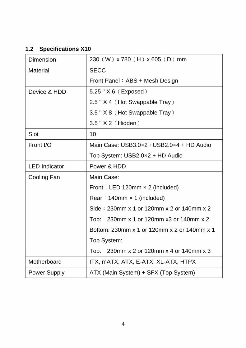
1.2 Specifications X10
Dimension 230(W)x 780(H)x 605(D)mm
Material SECC
Front Panel:ABS + Mesh Design
Device & HDD 5.25 '' X 6(Exposed)
2.5 '' X 4(Hot Swappable Tray)
3.5 '' X 8(Hot Swappable Tray)
3.5 '' X 2(Hidden)
Slot 10
Front I/O Main Case: USB3.0×2 +USB2.0×4 + HD Audio
Top System: USB2.0×2 + HD Audio
LED Indicator Power & HDD
Cooling Fan Main Case:
Front:LED 120mm × 2 (included)
Rear:140mm × 1 (included)
Side:230mm x 1 or 120mm x 2 or 140mm x 2
Top: 230mm x 1 or 120mm x3 or 140mm x 2
Bottom: 230mm x 1 or 120mm x 2 or 140mm x 1
Top System:
Top: 230mm x 2 or 120mm x 4 or 140mm x 3
Motherboard ITX, mATX, ATX, E-ATX, XL-ATX, HTPX
Power Supply ATX (Main System) + SFX (Top System)
5
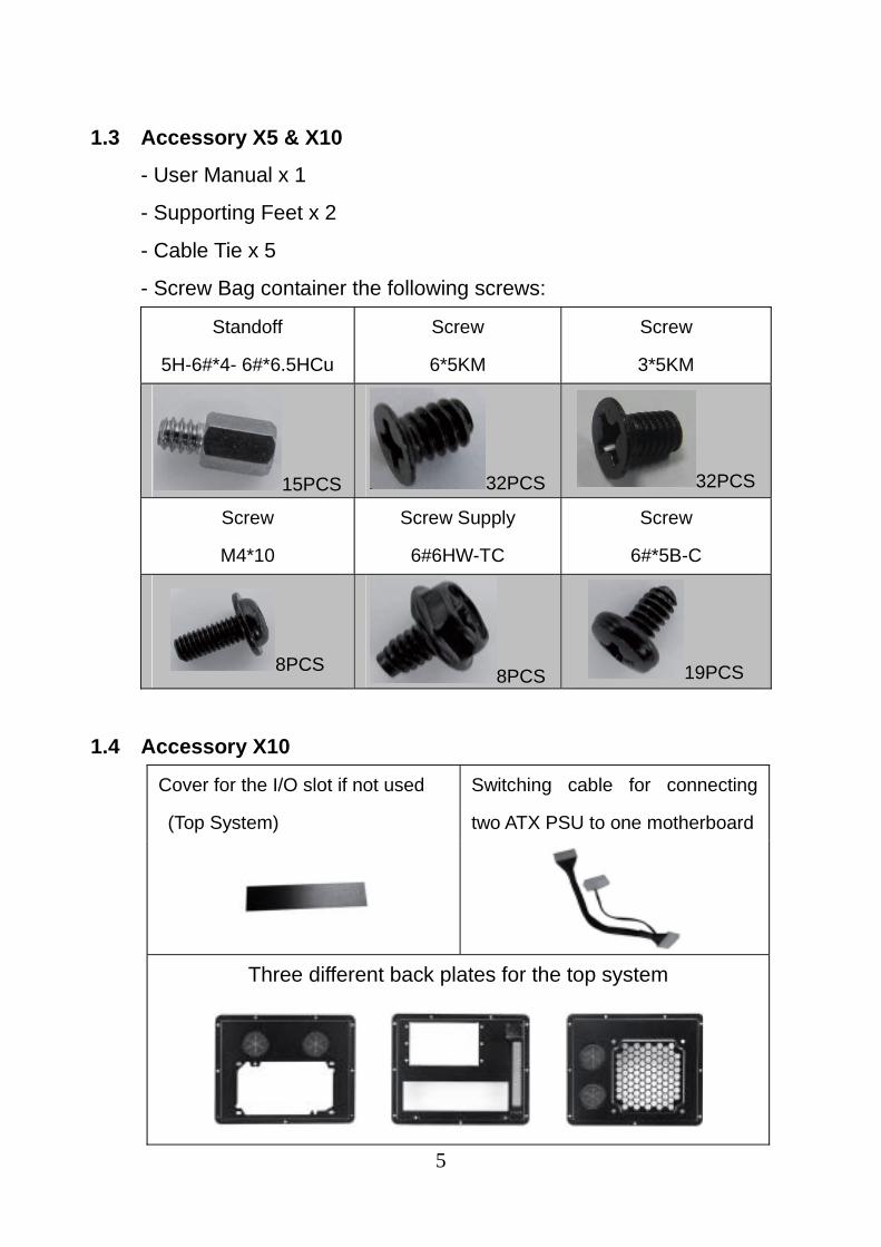
1.3 Accessory X5 & X10
- User Manual x 1
- Supporting Feet x 2
- Cable Tie x 5
- Screw Bag container the following screws:
Standoff
5H-6#*4- 6#*6.5HCu
Screw
6*5KM
Screw
3*5KM
15PCS 32PCS 32PCS
Screw
M4*10
Screw Supply
6#6HW-TC
Screw
6#*5B-C
8PCS 8PCS 19PCS
1.4 Accessory X10
Cover for the I/O slot if not used
(Top System)
Switching cable for connecting
two ATX PSU to one motherboard
Three different back plates for the top system
6
Chapter 2. Installation Guide
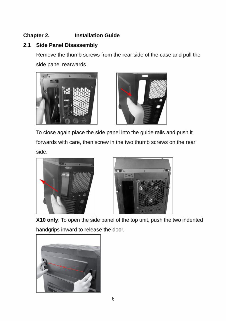
2.1 Side Panel Disassembly
Remove the thumb screws from the rear side of the case and pull the
side panel rearwards.
To close again place the side panel into the guide rails and push it
forwards with care, then screw in the two thumb screws on the rear
side.
X10 only: To open the side panel of the top unit, push the two indented
handgrips inward to release the door.
7
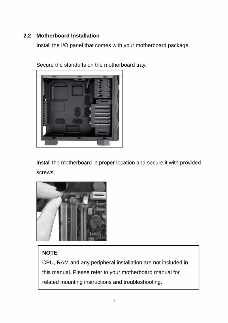
2.2 Motherboard Installation
Install the I/O panel that comes with your motherboard package.
Secure the standoffs on the motherboard tray.
Install the motherboard in proper location and secure it with provided
screws.
NOTE:
CPU, RAM and any peripheral installation are not included in
this manual. Please refer to your motherboard manual for
related mounting instructions and troubleshooting.
8
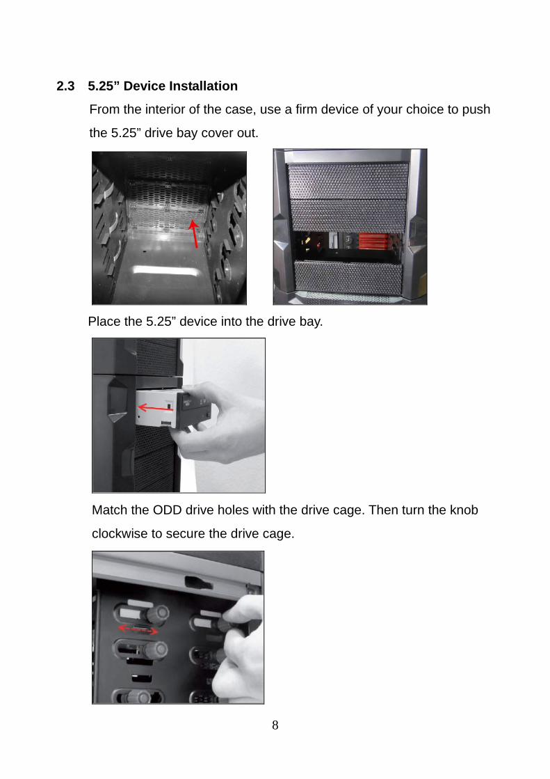
2.3 5.25” Device Installation
From the interior of the case, use a firm device of your choice to push
the 5.25” drive bay cover out.
Place the 5.25” device into the drive bay.
Match the ODD drive holes with the drive cage. Then turn the knob
clockwise to secure the drive cage.
9
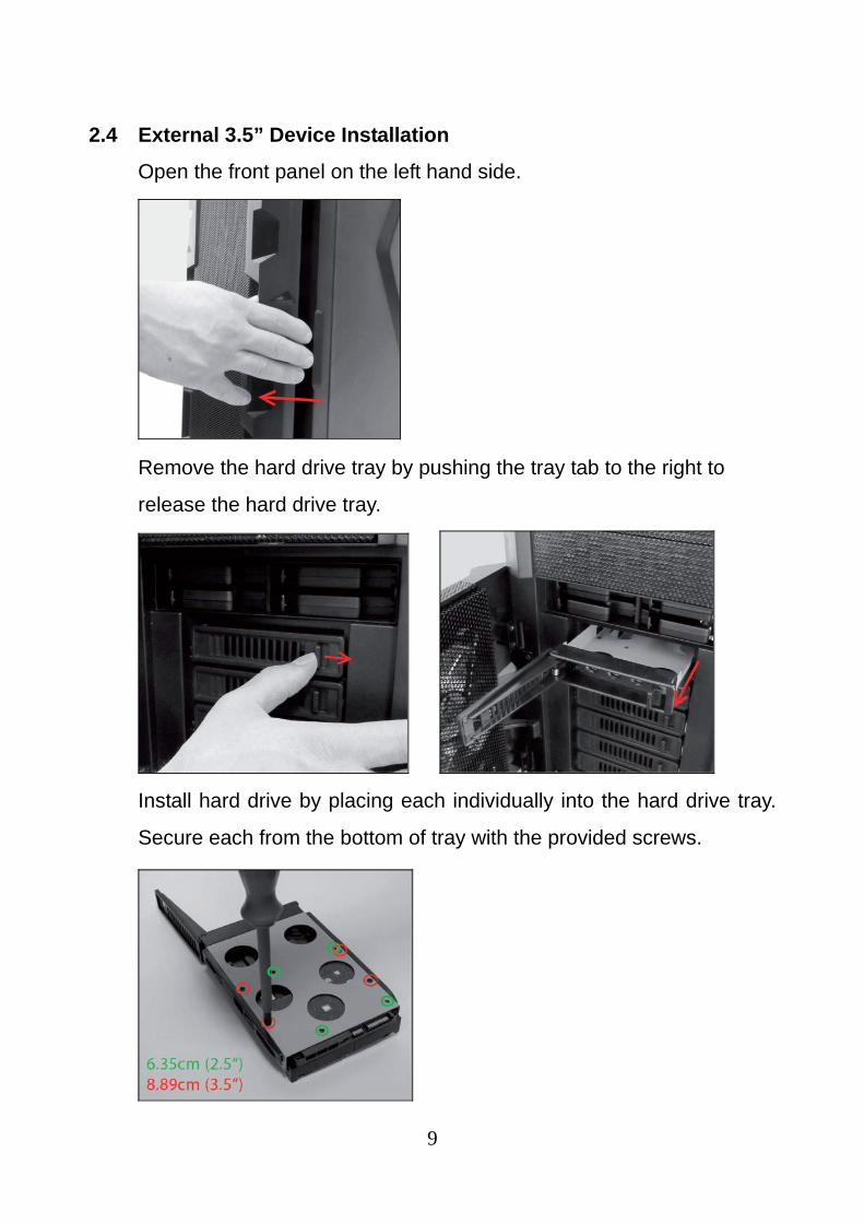
2.4 External 3.5” Device Installation
Open the front panel on the left hand side.
Remove the hard drive tray by pushing the tray tab to the right to
release the hard drive tray.
Install hard drive by placing each individually into the hard drive tray.
Secure each from the bottom of tray with the provided screws.
10
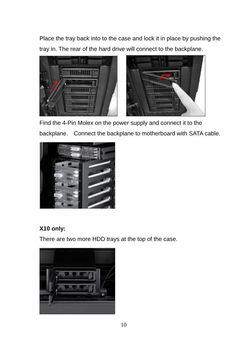
Place the tray back into to the case and lock it in place by pushing the
tray in. The rear of the hard drive will connect to the backplane.
Find the 4-Pin Molex on the power supply and connect it to the
backplane. Connect the backplane to motherboard with SATA cable.
X10 only:
There are two more HDD trays at the top of the case.
11
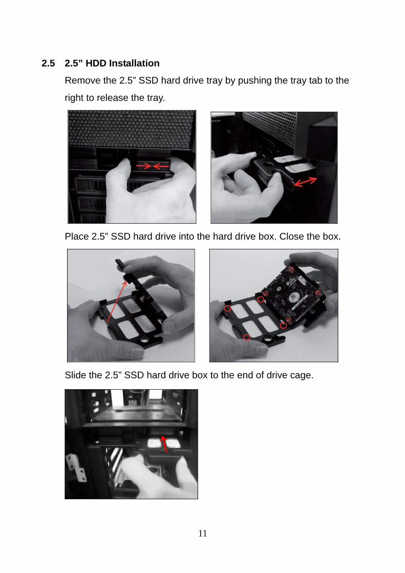
2.5 2.5” HDD Installation
Remove the 2.5” SSD hard drive tray by pushing the tray tab to the
right to release the tray.
Place 2.5” SSD hard drive into the hard drive box. Close the box.
Slide the 2.5” SSD hard drive box to the end of drive cage.
12
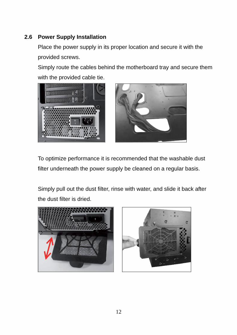
2.6 Power Supply Installation
Place the power supply in its proper location and secure it with the
provided screws.
Simply route the cables behind the motherboard tray and secure them
with the provided cable tie.
To optimize performance it is recommended that the washable dust
filter underneath the power supply be cleaned on a regular basis.
Simply pull out the dust filter, rinse with water, and slide it back after
the dust filter is dried.

13
2.7 Fan Installation
Fan Installation on the Side Panel
Take out the dust filter from the side panel.
Unscrew these three screws from the back of the side panel.
Pull the plastic cover backward to remove the cover
14
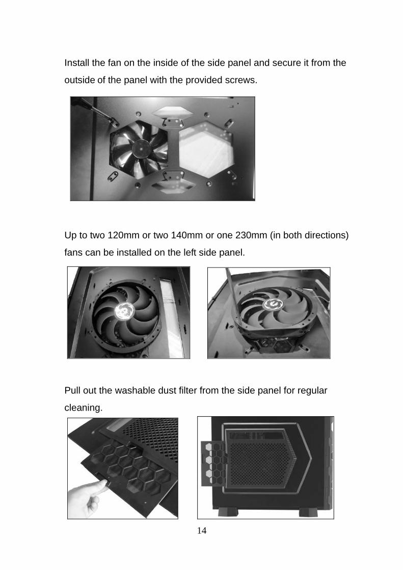
Install the fan on the inside of the side panel and secure it from the
outside of the panel with the provided screws.
Up to two 120mm or two 140mm or one 230mm (in both directions)
fans can be installed on the left side panel.
Pull out the washable dust filter from the side panel for regular
cleaning.
15
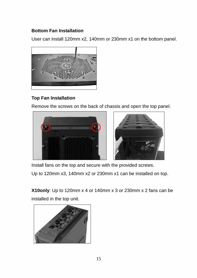
Bottom Fan Installation
User can install 120mm x2, 140mm or 230mm x1 on the bottom panel.
Top Fan Installation
Remove the screws on the back of chassis and open the top panel.
Install fans on the top and secure with the provided screws.
Up to 120mm x3, 140mm x2 or 230mm x1 can be installed on top.
X10only: Up to 120mm x 4 or 140mm x 3 or 230mm x 2 fans can be
installed in the top unit.

16
2.8 Water Cooling Installation
The pre-drilled water cooling holes at the case rear is for installing the
external water cooling system.
A 360 mm radiator may be installed on the top of chassis using the
pre-drilled screw holes.
X10only:
A 480 mm radiator may be installed on the top plate using the
pre-drilled screw holes.
17
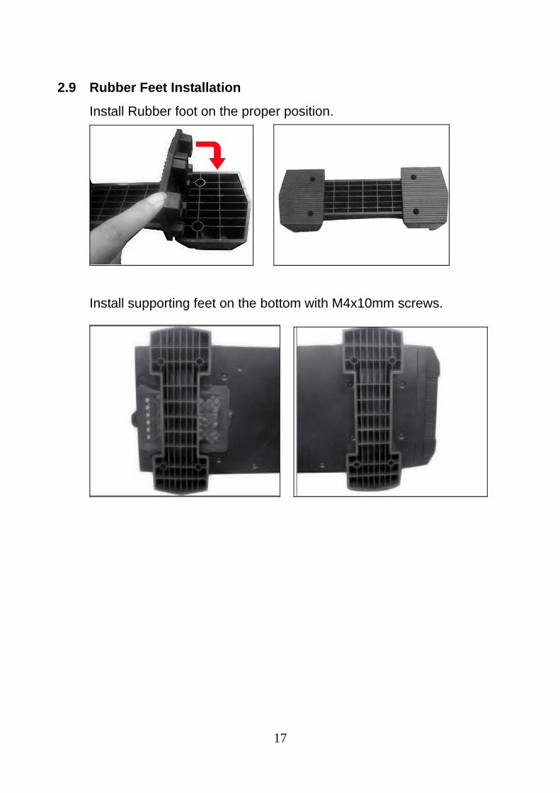
2.9 Rubber Feet Installation
Install Rubber foot on the proper position.
Install supporting feet on the bottom with M4x10mm screws.

18
2.10 Front I/O Installation Guide
X10 only: The unit comes with two sets of front ports:
Please refer to the following illustration of front I/O connector and your
motherboard user manual.
USB 3.0
USB 2.0
HD Audio
Front I/O ports for Top System
Front I/O ports for Main Case
19
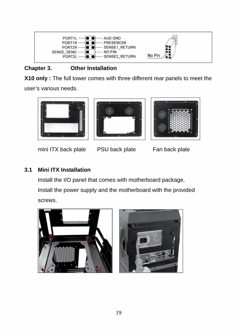
Chapter 3. Other Installation
X10 only : The full tower comes with three different rear panels to meet the
user’s various needs.
mini ITX back plate PSU back plate Fan back plate
3.1 Mini ITX Installation
Install the I/O panel that comes with motherboard package.
Install the power supply and the motherboard with the provided
screws.

20
22
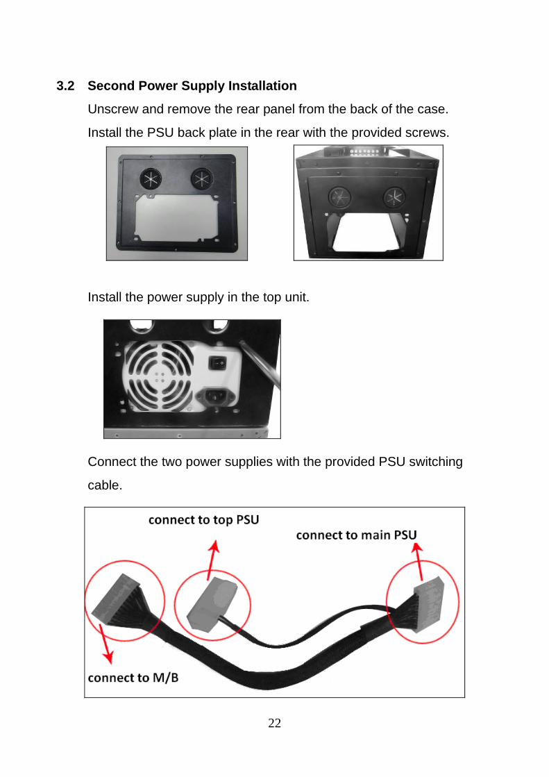
3.2 Second Power Supply Installation
Unscrew and remove the rear panel from the back of the case.
Install the PSU back plate in the rear with the provided screws.
Install the power supply in the top unit.
Connect the two power supplies with the provided PSU switching
cable.

22
Streak Products, Inc. • www.ultraproducts.com
© 2013 Streak Products, Inc.
Ultra® is a registered trademark and Ultra ETORQUE™ is a trademark of Streak
Products, Inc.
8300 West Flagler Street, #121-106, Miami, FL 33144
All other trademarks listed are the property of their respective owners.
Streak Products is not responsible for typographical or photographic errors.
TECHNICAL SUPPORT (888) 222-5487
WARNING: Keep out of reach of children-contains sharp edges that may harm
children.
Recommended