XBee 868LP RF Modules
User Guide
Revision history—90002126
Revision Date Description
M July, 2015 Corrected the P3 and P4 AT command parameters. Corrected theindoor/urban range and outdoor/line-of-sight range parameters.
N February,2016
Added the I/O Data Sample RX Indicator (0x92) frame to the API section.Corrected references to REC 70-03. Removed “865” from the guide.
P July 2016 Updated pushbutton drawing and ISO spec number.
R October 2016 Converted to the new MadCap Flare format with minor updates andadded the information from the XBee 868LP Getting Started Guide(90002127).
S June 2017 Modified regulatory and certification information as required by RED(Radio Equipment Directive).
Trademarks and copyrightDigi, Digi International, and the Digi logo are trademarks or registered trademarks in the UnitedStates and other countries worldwide. All other trademarks mentioned in this document are theproperty of their respective owners.© 2017 Digi International Inc. All rights reserved.
DisclaimersInformation in this document is subject to change without notice and does not represent acommitment on the part of Digi International. Digi provides this document “as is,” without warranty ofany kind, expressed or implied, including, but not limited to, the implied warranties of fitness ormerchantability for a particular purpose. Digi may make improvements and/or changes in this manualor in the product(s) and/or the program(s) described in this manual at any time.
WarrantyTo view product warranty information, go to the following website:www.digi.com/howtobuy/terms
Send commentsDocumentation feedback: To provide feedback on this document, send your comments [email protected].
XBee 868LP RF Modules User Guide 2

Customer supportDigi Technical Support: Digi offers multiple technical support plans and service packages to help ourcustomers get the most out of their Digi product. For information on Technical Support plans andpricing, contact us at +1 952.912.3444 or visit us at www.digi.com/support.
XBee 868LP RF Modules User Guide 3
Contents
XBee 868LP RF Modules User GuideXBee S8 hardware description 12European acceptance 12
Technical specificationsPerformance specifications 14LBT and AFA specifications 14Power requirements 15General specifications 15XBee 868LP RF Module Networking and security 16Regulatory conformity summary 16Serial communication specifications 16
UART pin assignments 16SPI pin assignments 17
GPIO specifications 17Hardware specifications for the programmable variant 17Mechanical drawings 18Pin signals 18Design notes 20
Power supply design 21Board layout 21Antenna performance 21Recommended pin connections 22Design notes for PCB antenna devices 22Design notes for RF pad devices 23Module operation for the programmable variant 26Programmable XBee SDK 27
Get startedSet up the devices 29
Before you begin 29Connect the hardware 30Step 1: Download and install XCTU 31Step 2: Set up your first wireless connection 33Step 3: Create a mesh network 38Step 4: Use API mode to talk to XBee modules 42
Do more with your XBee modules 46Update the firmware 46
XBee 868LP RF Modules User Guide 4
XBee 868LP RF Modules User Guide 5
Configure remote devices 47Set up and perform a range test 48Configure basic synchronous sleep support 52Set up basic encryption for an XBee network 57
Learn more about XBee module features 58Unicast versus broadcast transmissions 58Analog inputs and digital inputs and outputs 59Sleepmodes 59Transparent and API operating modes 59
Troubleshooting 60Cannot install device driver 60Use LEDs to identify XBee modules 60No remote devices to select for a range test 61Port in use 61XCTU cannot discover devices 62XCTU cannot discover remote devices 63XCTU cannot discover remote devices for a range test 63XCTU installation error 63
OperationOperation 66Listen Before Talk and Automatic Frequency Agility 66Single frequency mode bandmode 67Serial communications 67
UART data flow 67SPI communications 68SPI operation 69
Configuration considerations 71Serial port selection 71Data format 71SPI parameters 72
Serial buffers 72Serial receive buffer 72Serial transmit buffer 72
UART flow control 72CTS flow control 73RTS flow control 73
Force UART operation 73Condition 73Solution 73
Serial interface protocols 73Transparent operating mode 73API operating mode 74Comparing Transparent and API modes 74
ModesTransmit mode 77Receive mode 77Commandmode 77
Enter Commandmode 77Send AT commands 78Apply command changes 78

XBee 868LP RF Modules User Guide 6
Exit Commandmode 79Sleepmode 79
Sleep modesAbout sleepmodes 81
Asynchronous modes 81Synchronous modes 81
Normal mode 81Asynchronous pin sleepmode 82Asynchronous cyclic sleepmode 82Asynchronous cyclic sleep with pin wake upmode 82Synchronous sleep support mode 82Synchronous cyclic sleepmode 82Wake timer 83Indirect messaging and polling 83
Indirect messaging 83Polling 83
Sleeping routers 84Sleep coordinator sleepmodes in the DigiMesh network 84
Synchronization messages 84Become a sleep coordinator 87Select sleep parameters 89Start a sleeping synchronous network 89Add a new node to an existing network 90Change sleep parameters 91Rejoin nodes that lose sync 91Diagnostics 92
Advanced application featuresRemote configuration commands 95
Send a remote command 95Apply changes on remote devices 95Remote command responses 95
Network commissioning and diagnostics 95Configure devices 95Network link establishment andmaintenance 96Place devices 97Device discovery 98Link reliability 98Commissioning pushbutton and associate LED 101
I/O line monitoring 104I/O samples 104Queried sampling 104Periodic I/O sampling 106Detect digital I/O changes 107
General Purpose Flash Memory 107Access General Purpose Flash Memory 107Work with flash memory 108
General Purpose Flash Memory commands 109PLATFORM_INFO_REQUEST (0x00) 109PLATFORM_INFO (0x80) 109ERASE (0x01) 110

XBee 868LP RF Modules User Guide 7
ERASE_RESPONSE (0x81) 110WRITE (0x02) and ERASE_THEN_WRITE (0x03) 111WRITE _RESPONSE (0x82) and ERASE_THEN_WRITE_RESPONSE (0x83) 111READ (0x04) 112READ_RESPONSE (0x84) 113FIRMWARE_VERIFY (0x05) and FIRMWARE_VERIFY_AND_INSTALL(0x06) 113FIRMWARE_VERIFY_RESPONSE (0x85) 114FIRMWARE_VERIFY _AND_INSTALL_RESPONSE (0x86) 114
Over-the-air firmware updates 115Distribute the new application 115Verify the new application 116Install the application 116
Networking methodsDirected Broadcast/Repeater mode 118Point to Point/Multipoint mode 118
Permanent (dedicated) 118Switched 118
DigiMesh networking 118DigiMesh feature set 119
Networking concepts 120Device Configuration 120Network ID 120
Data transmission and routing 120Unicast addressing 120Broadcast addressing 120Routing 121Route discovery 121DigiMesh throughput 121Transmission timeouts 122
AT commandsSpecial commands 125
AC (Apply Changes) 125FR (Software Reset) 125RE command 125WR command 125
MAC/PHY commands 126CM (Channel Mask) 126HP (Preamble ID) 126ID (Network ID) 126MT (Broadcast Multi-Transmits) 127PL (TX Power Level) 127RR (Unicast Mac Retries) 127ED (Energy Detect) 128
Diagnostic commands 128BC (Bytes Transmitted) 128DB (Last Packet RSSI) 128ER (Received Error Count) 129GD (Good Packets Received) 129EA (MAC ACK Timeouts) 129TR (Transmission Errors) 129

XBee 868LP RF Modules User Guide 8
UA (MAC Unicast Transmission Count) 130%H (MAC Unicast One Hop Time) 130%8 (MAC Broadcast One Hop Time) 130
Network commands 130CE (Node Messaging Options) 130BH command 131NH (Network Hops) 131NN (Network Delay Slots) 131MR (Mesh Unicast Retries) 132
Addressing commands 132SH command 132SL command 132DH command 132DL command 133TO command 133NI command 134NT (Node Discover Timeout) 134NO (Node Discovery Options) 134CI (Cluster ID) 135DE command 135SE command 135
Addressing discovery/configuration commands 136AG (Aggregator Support) 136DN (Discover Node) 136ND (Network Discover) 136FN (Find Neighbors) 137
Diagnostic - addressing commands 137N? (Network Discovery Timeout) 138
Security commands 138EE (Security Enable) 138KY (AES Encryption Key) 138
Serial interfacing commands 139BD (Baud Rate) 139NB (Parity) 139SB command 140RO commandt) 140FT (Flow Control Threshold) 140API Mode 141AO command 141
I/O settings commands 141CB command 141D0 (AD0/DIO0 Configuration) 142D1 (DIO1/AD1) 142D2 (DIO2/AD2) 143D3 (DIO3/AD3) 143D4 (DIO4/AD4) 143D5 (DIO5/ASSOCIATED_INDICATOR) 144D6 (DIO6/RTS) 144D7 (DIO7/CTS) 145D8 (DIO8/SLEEP_REQUEST) 145D9 (DIO9/ON_SLEEP) 145P0 (DIO10/RSSI/PWM0 Configuration) 146P1 (DIO11/PWM1 Configuration) 146P2 (DIO12 Configuration) 147P3 (DIO13/DOUT) 147
XBee 868LP RF Modules User Guide 9
P4 (DIO14/DIN) 148P5 (SPI_MISO) 148P6 (SPI_MOSI Configuration) 148P7 (DIO17/SPI_SSEL ) 149P8 (DIO18/SPI_SCLK) 149P9 (SPI_ATTN) 149PD (Pull Up/Down Direction) 150PR (Pull-up/Down Resistor Enable) 150M0 (PWM0 Duty Cycle) 151M1 (PWM1 Duty Cycle) 151LT command 152RP command 152
I/O sampling commands 152AV (Analog Voltage Reference) 152IC (DIO Change Detection) 152IF (Sleep Sample Rate) 153IR (I/O Sample Rate) 153TP (Temperature) 154IS command 154%V (Voltage Supply Monitoring) 154
Sleep commands 154SM command 155SO command 155SN command 156SP (Sleep Period) 156ST (Wake Time) 156WH (Wake Host) 157
Diagnostic - sleep status/timing commands 157SS (Sleep Status) 157OS (Operating Sleep Time) 158OW (Operating Wake Time) 158MS (Missed Sync Messages) 158SQ (Missed Sleep Sync Count) 158
Commandmode options 159CC (Command Sequence Character) 159CT command 159CN command 159GT command 159
Firmware commands 160VL command 160VR command 160HV command 160HS (Hardware Series) 160DD command 160NP (Maximum Packet Payload Bytes) 161CK (Configuration CRC) 161
Operate in API modeAPI mode overview 163
API frame format 163Data bytes that need to be escaped: 164Calculate and verify checksums 165API UART exchanges 166Code to support future API frames 167
XBee 868LP RF Modules User Guide 10
Frame data 168AT Command Frame - 0x08 169AT Command - Queue Parameter Value frame - 0x09 170Transmit Request frame - 0x10 171Explicit Addressing Command frame - 0x11 174Remote AT Command Request frame - 0x17 177AT Command Response frame - 0x88 179Modem Status frame - 0x8A 181Transmit Status frame - 0x8B 182Route Information Packet frame - 0x8D 184Aggregate Addressing Update frame - 0x8E 187Receive Packet frame - 0x90 189Explicit Rx Indicator frame - 0x91 191Data Sample Rx Indicator frame - 0x92 193Node Identification Indicator frame - 0x95 195Remote Command Response frame - 0x97 198
Regulatory informationEurope 201
Maximum power and frequency specifications 201OEM labeling requirements 202Declarations of conformity 203
Antennas 203
Migrate from XBee through-hole to surface-mount devicesPin mapping 205Mounting 206
Manufacturing informationRecommended solder reflow cycle 209Recommended footprint 209Flux and cleaning 211Reworking 211

XBee 868LP RF Modules User Guide
The Digi XBee 868LP RF Modules provide wireless connectivity to end-point devices in mesh networks.With the XBee, users can have their network up-and-running in a matter of minutes withoutconfiguration or additional development. The Digi XBee 868LP RF Module consists of firmware loadedonto Digi XBee S8 hardware.You can build networks up to 128 nodes using the XBee modules. For larger networks up to 1000+nodes, Digi offers RF Optimization Services to assist with proper network configuration. Contact DigiTechnical Support for more details.
Note The Digi XBee 868LP RF Modules are not compatible with other XBee products.
XBee S8 hardware description 12European acceptance 12
XBee 868LP RF Modules User Guide 11

XBee 868LP RF Modules User Guide XBee S8 hardware description
XBee 868LP RF Modules User Guide 12
XBee S8 hardware descriptionThe XBee S8 radio module hardware consists of an Energy Micro EFM®32G230F128 microcontroller, anAnalog Devices ADF7023 radio transceiver, and in the Programmable version, a NXP MC9S08QE32microcontroller.
European acceptanceThe Digi XBee 868LP is manufactured under ISO 900:2015 registered standards.The Digi XBee 868LP RF Modules are optimized for use in Europe and other regions. For moreinformation, see Regulatory information.

Technical specifications
Performance specifications 14LBT and AFA specifications 14Power requirements 15General specifications 15XBee 868LP RF Module Networking and security 16Regulatory conformity summary 16Serial communication specifications 16GPIO specifications 17Hardware specifications for the programmable variant 17Mechanical drawings 18Pin signals 18Design notes 20
XBee 868LP RF Modules User Guide 13
Technical specifications Performance specifications
XBee 868LP RF Modules User Guide 14
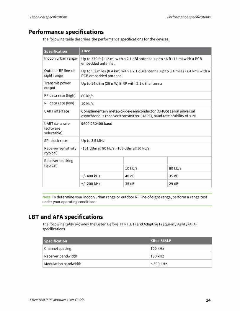
Performance specificationsThe following table describes the performance specifications for the devices.
Specification XBee
Indoor/urban range Up to 370 ft (112 m) with a 2.1 dBi antenna, up to 46 ft (14 m) with a PCBembedded antenna.
Outdoor RF line-of-sight range
Up to 5.2 miles (8.4 km) with a 2.1 dBi antenna, up to 0.4 miles (.64 km) with aPCB embedded antenna.
Transmit poweroutput
Up to 14 dBm (25 mW) EIRP with 2.1 dBi antenna
RF data rate (high) 80 kb/s
RF data rate (low) 10 kb/s
UART interface Complementary metal–oxide–semiconductor (CMOS) serial universalasynchronous receiver/transmitter (UART), baud rate stability of <1%.
UART data rate(softwareselectable)
9600-230400 baud
SPI clock rate Up to 3.5 MHz
Receiver sensitivity(typical)
-101 dBm@ 80 kb/s, -106 dBm@ 10 kb/s.
Receiver blocking(typical)
10 kb/s 80 kb/s
+/- 400 kHz 40 dB 35 dB
+/- 200 kHz 35 dB 29 dB
Note To determine your indoor/urban range or outdoor RF line-of-sight range, perform a range testunder your operating conditions.
LBT and AFA specificationsThe following table provides the Listen Before Talk (LBT) and Adaptive Frequency Agility (AFA)specifications.
Specification XBee 868LP
Channel spacing 100 kHz
Receiver bandwidth 150 kHz
Modulation bandwidth < 300 kHz
Technical specifications Power requirements
XBee 868LP RF Modules User Guide 15
Specification XBee 868LP
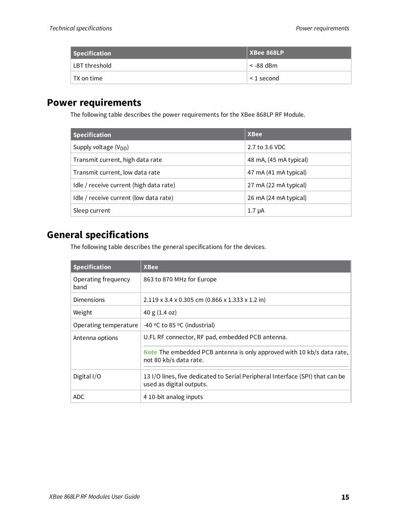
LBT threshold < -88 dBm
TX on time < 1 second
Power requirementsThe following table describes the power requirements for the XBee 868LP RF Module.
Specification XBee
Supply voltage (VDD) 2.7 to 3.6 VDC
Transmit current, high data rate 48 mA, (45 mA typical)
Transmit current, low data rate 47 mA (41 mA typical)
Idle / receive current (high data rate) 27 mA (22 mA typical)
Idle / receive current (low data rate) 26 mA (24 mA typical)
Sleep current 1.7 µA
General specificationsThe following table describes the general specifications for the devices.
Specification XBee
Operating frequencyband
863 to 870 MHz for Europe
Dimensions 2.119 x 3.4 x 0.305 cm (0.866 x 1.333 x 1.2 in)
Weight 40 g (1.4 oz)
Operating temperature -40 ºC to 85 ºC (industrial)
Antenna options U.FL RF connector, RF pad, embedded PCB antenna.
Note The embedded PCB antenna is only approved with 10 kb/s data rate,not 80 kb/s data rate.
Digital I/O 13 I/O lines, five dedicated to Serial Peripheral Interface (SPI) that can beused as digital outputs.
ADC 4 10-bit analog inputs

Technical specifications XBee 868LP RF Module Networking and security
XBee 868LP RF Modules User Guide 16
XBee 868LP RF Module Networking and securityThe following table describes the networking and security specifications for the devices.
Specification XBee
Supported network topologies Mesh, repeater, point-to-point, point-to-multipoint, peer-to-peer.
Number of channels, user selectablechannels
30 channels, LBT + AFA
Addressing options Personal Area Network identifier (PAN ID) and 64-bitaddresses.
Encryption 128 bit Advanced Encryption Standard (AES)
Note For more information about the number of user selectable channels, see OEM labelingrequirements for countries in the European Community.
Regulatory conformity summaryThis table describes the agency approvals for the devices.
Specification XBee
Europe (CE) Yes
Serial communication specificationsThe XBee 868LP RF Module supports both Universal Asynchronous Receiver / Transmitter (UART) andSerial Peripheral Interface (SPI) serial connections.
UART pin assignments
UART Pins Module Pin Number
DOUT 3
DIN / CONFIG 4
CTS / DIO7 25
RTS / DIO6 29
For more information on UART operation, see UART data flow.
Technical specifications GPIO specifications
XBee 868LP RF Modules User Guide 17
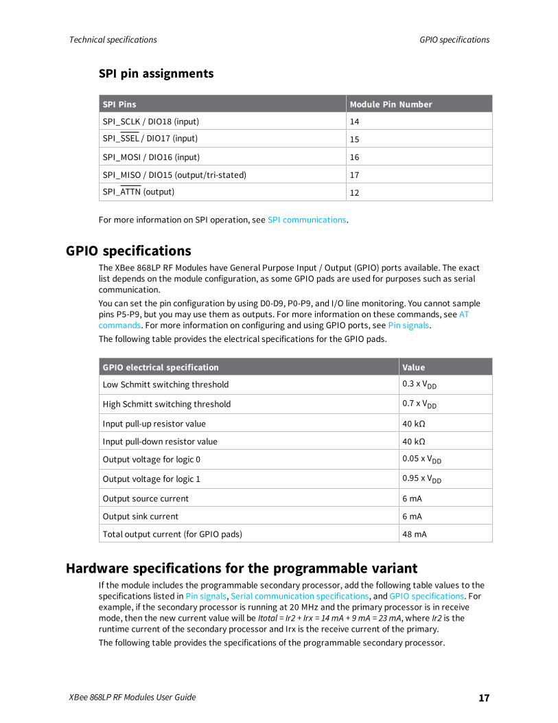
SPI pin assignments
SPI Pins Module Pin Number
SPI_SCLK / DIO18 (input) 14
SPI_SSEL / DIO17 (input) 15
SPI_MOSI / DIO16 (input) 16
SPI_MISO / DIO15 (output/tri-stated) 17
SPI_ATTN (output) 12
For more information on SPI operation, see SPI communications.
GPIO specificationsThe XBee 868LP RF Modules have General Purpose Input / Output (GPIO) ports available. The exactlist depends on the module configuration, as some GPIO pads are used for purposes such as serialcommunication.You can set the pin configuration by using D0-D9, P0-P9, and I/O line monitoring. You cannot samplepins P5-P9, but you may use them as outputs. For more information on these commands, see ATcommands. For more information on configuring and using GPIO ports, see Pin signals.The following table provides the electrical specifications for the GPIO pads.
GPIO electrical specification Value
Low Schmitt switching threshold 0.3 x VDD
High Schmitt switching threshold 0.7 x VDD
Input pull-up resistor value 40 kΩ
Input pull-down resistor value 40 kΩ
Output voltage for logic 0 0.05 x VDD
Output voltage for logic 1 0.95 x VDD
Output source current 6 mA
Output sink current 6 mA
Total output current (for GPIO pads) 48 mA
Hardware specifications for the programmable variantIf the module includes the programmable secondary processor, add the following table values to thespecifications listed in Pin signals, Serial communication specifications, and GPIO specifications. Forexample, if the secondary processor is running at 20 MHz and the primary processor is in receivemode, then the new current value will be Itotal = Ir2 + Irx = 14 mA + 9mA = 23 mA, where Ir2 is theruntime current of the secondary processor and Irx is the receive current of the primary.The following table provides the specifications of the programmable secondary processor.

Technical specifications Mechanical drawings
XBee 868LP RF Modules User Guide 18
Optional secondary processorspecification
Add to RX, TX, and sleep currents specifications dependingon mode of operation
Runtime current for 32 k runningat 20 MHz
+14 mA
Runtime current for 32 k runningat 1 MHz
+1 mA
Sleep current +0.5 µA typical
VREF Range 1.8 VDC to VDD
Microcontroller NXP Flexis 8-bit S08 microcontroller NXP S08QE FamilyPart number: MC9S08QE32
Mechanical drawingsThe following mechanical drawings of the XBee 868LP RF Modules show all dimensions in inches.Antenna options are not shown.
Pin signalsThe following table describes the pin assignments for the devices. A horizontal line above the signalname indicates low-asserted signals.
Pin# Name DirectionDefaultstate Description
1 GND - - Ground
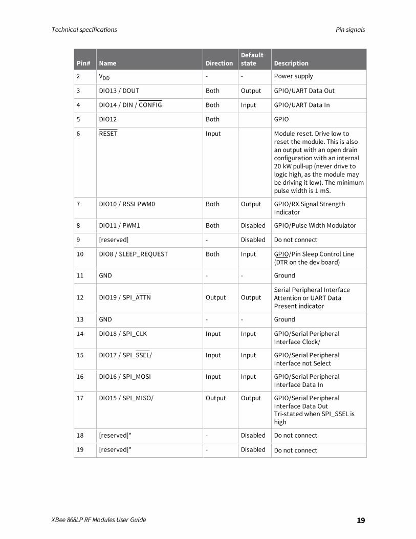
Technical specifications Pin signals
XBee 868LP RF Modules User Guide 19
Pin# Name DirectionDefaultstate Description
2 VDD - - Power supply
3 DIO13 / DOUT Both Output GPIO/UART Data Out
4 DIO14 / DIN / CONFIG Both Input GPIO/UART Data In
5 DIO12 Both GPIO
6 RESET Input Module reset. Drive low toreset the module. This is alsoan output with an open drainconfiguration with an internal20 kW pull-up (never drive tologic high, as the module maybe driving it low). The minimumpulse width is 1 mS.
7 DIO10 / RSSI PWM0 Both Output GPIO/RX Signal StrengthIndicator
8 DIO11 / PWM1 Both Disabled GPIO/Pulse Width Modulator
9 [reserved] - Disabled Do not connect
10 DIO8 / SLEEP_REQUEST Both Input GPIO/Pin Sleep Control Line(DTR on the dev board)
11 GND - - Ground
12 DIO19 / SPI_ATTN Output OutputSerial Peripheral InterfaceAttention or UART DataPresent indicator
13 GND - - Ground
14 DIO18 / SPI_CLK Input Input GPIO/Serial PeripheralInterface Clock/
15 DIO17 / SPI_SSEL/ Input Input GPIO/Serial PeripheralInterface not Select
16 DIO16 / SPI_MOSI Input Input GPIO/Serial PeripheralInterface Data In
17 DIO15 / SPI_MISO/ Output Output GPIO/Serial PeripheralInterface Data OutTri-stated when SPI_SSEL ishigh
18 [reserved]* - Disabled Do not connect
19 [reserved]* - Disabled Do not connect
Technical specifications Design notes
XBee 868LP RF Modules User Guide 20
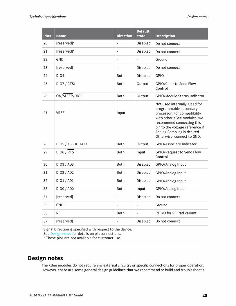
Pin# Name DirectionDefaultstate Description
20 [reserved]* - Disabled Do not connect
21 [reserved]* - Disabled Do not connect
22 GND - - Ground
23 [reserved] - Disabled Do not connect
24 DIO4 Both Disabled GPIO
25 DIO7 / CTS/ Both Output GPIO/Clear to Send FlowControl
26 ON/SLEEP/DIO9 Both Output GPIO/Module Status Indicator
27 VREF Input -
Not used internally. Used forprogrammable secondaryprocessor. For compatibilitywith other XBee modules, werecommend connecting thispin to the voltage reference ifAnalog Sampling is desired.Otherwise, connect to GND.
28 DIO5 / ASSOCIATE/ Both Output GPIO/Associate Indicator
29 DIO6 / RTS Both Input GPIO/Request to Send FlowControl
30 DIO3 / AD3 Both Disabled GPIO/Analog Input
31 DIO2 / AD2 Both Disabled GPIO/Analog Input
32 DIO1 / AD1 Both Disabled GPIO/Analog Input
33 DIO0 / AD0 Both Input GPIO/Analog Input
34 [reserved] - Disabled Do not connect
35 GND - - Ground
36 RF Both - RF I/O for RF Pad Variant
37 [reserved] - Disabled Do not connect
Signal Direction is specified with respect to the device.See Design notes for details on pin connections.* These pins are not available for customer use.
Design notesThe XBee modules do not require any external circuitry or specific connections for proper operation.However, there are some general design guidelines that we recommend to build and troubleshoot a

Technical specifications Design notes
XBee 868LP RF Modules User Guide 21
robust design.
Power supply designA poor power supply can lead to poor radio performance, especially if you do not keep the supplyvoltage within tolerance or if the noise is excessive. To help reduce noise, place a 1.0 µF and 47 pFcapacitor as near as possible to pin 2 on the PCB. If you are using a switching regulator for the powersupply, switch the frequencies above 500 kHz. Limit the power supply ripple to a maximum 250 mVpeak to peak.For designs using the programmable modules, we recommend an additional 10 µF decoupling capnear pin 2 of the device. The nearest proximity to pin 2 of the three caps should be in the followingorder:
1. 47 pf
2. 1 µF
3. 10 µF
Board layoutWe design XBee modules to be self-sufficient and have minimal sensitivity to nearby processors,crystals or other printed circuit board (PCB) components. Keep power and ground traces thicker thansignal traces andmake sure that they are able to comfortably support the maximum currentspecifications. There are no other special PCB design considerations to integrate XBee modules, withthe exception of antennas.To view a recommended PCB footprint for the module, see Manufacturing information.
Antenna performanceAntenna location is important for optimal performance. The following suggestions help you achieveoptimal antenna performance. Point the antenna up vertically (upright). Antennas radiate and receivethe best signal perpendicular to the direction they point, so a vertical antenna's omnidirectionalradiation pattern is strongest across the horizon.Position the antennas away from metal objects whenever possible. Metal objects between thetransmitter and receiver can block the radiation path or reduce the transmission distance. Objectsthat are often overlooked include:
n Metal poles
n Metal studs
n Structure beams
n Concrete, which is usually reinforced with metal rods
If you place the device inside a metal enclosure, use an external antenna. Common objects that havemetal enclosures include:
n Vehicles
n Elevators
n Ventilation ducts
n Refrigerators
n Microwave ovens

Technical specifications Design notes
XBee 868LP RF Modules User Guide 22
n Batteries
n Tall electrolytic capacitors
Use the following additional guidelines for optimal antenna performance:
n Do not place XBee modules with the chip antenna inside a metal enclosure.
n Do not place any ground planes or metal objects above or below the antenna.
n For the best results, mount the device at the edge of the host PCB. Ensure that the ground,power, and signal planes are vacant immediately below the antenna section.
Recommended pin connectionsThe only required pin connections for two-way communication are VDD, GND, DOUT and DIN. Tosupport serial firmware updates, you must connect VDD, GND, DOUT, DIN, RTS, and DTR.Do not connect any pins that are not in use. Use the PR and PD commands to pull all inputs on theradio high or low with 40k internal pull-up or pull-down resistors. Unused outputs do not require anyspecific treatment.For applications that need to ensure the lowest sleep current, never leave unconnected inputsfloating. Use internal or external pull-up or pull-down resistors, or set the unused I/O lines to outputs.You can connect other pins to external circuitry for convenience of operation including the AssociateLED pad (pad 28) and the Commissioning pad (pad 33). The Associate LED pad flashes differentlydepending on the state of the module to the network, and a pushbutton attached to pad 33 canenable various join functions without having to send serial port commands. For more information seeCommissioning pushbutton and associate LED. The source and sink capabilities are limited to 6 mA onall I/O pads.Only the programmable versions of these devices use the VREF pad (pad 27). For compatibility withother XBee modules, we recommend connecting this pin to a voltage reference if you want to enableanalog sampling. Otherwise, connect to GND.
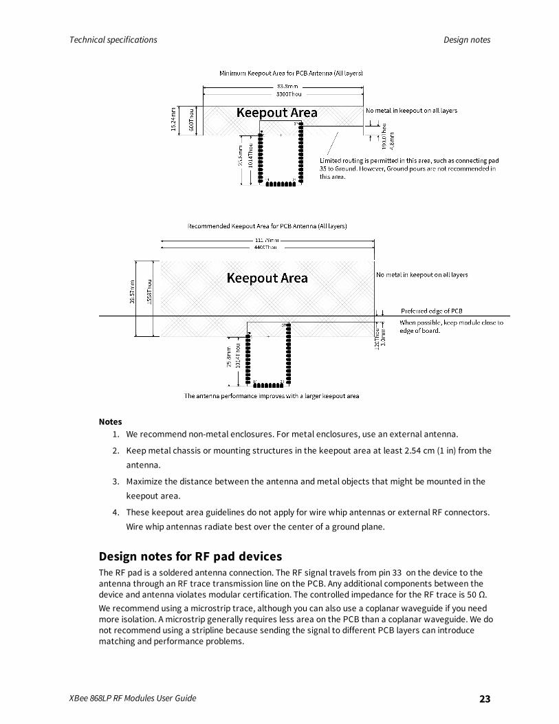
Design notes for PCB antenna devicesPosition PCB antenna devices so there are no ground planes or metal objects above or below theantenna. For best results, do not place the device in a metal enclosure, as this may greatly reduce therange. Place the device at the edge of the PCB on which it is mounted. Make sure the ground, powerand signal planes are vacant immediately below the antenna section.The following drawings illustrate important recommendations when you are designing with PCBantenna devices. For optimal performance, do not mount the device on the RF pad footprint describedin the next section, because the footprint requires a ground plane within the PCB antenna keep outarea.
Technical specifications Design notes
XBee 868LP RF Modules User Guide 23
Notes1. We recommend non-metal enclosures. For metal enclosures, use an external antenna.
2. Keepmetal chassis or mounting structures in the keepout area at least 2.54 cm (1 in) from theantenna.
3. Maximize the distance between the antenna andmetal objects that might be mounted in thekeepout area.
4. These keepout area guidelines do not apply for wire whip antennas or external RF connectors.Wire whip antennas radiate best over the center of a ground plane.
Design notes for RF pad devicesThe RF pad is a soldered antenna connection. The RF signal travels from pin 33 on the device to theantenna through an RF trace transmission line on the PCB. Any additional components between thedevice and antenna violates modular certification. The controlled impedance for the RF trace is 50 Ω.We recommend using a microstrip trace, although you can also use a coplanar waveguide if you needmore isolation. A microstrip generally requires less area on the PCB than a coplanar waveguide. We donot recommend using a stripline because sending the signal to different PCB layers can introducematching and performance problems.
Technical specifications Design notes
XBee 868LP RF Modules User Guide 24
Following good design practices is essential when implementing the RF trace on a PCB. Consider thefollowing points:
n Minimize the length of the trace by placing the RPSMA jack close to the device.
n Connect all of the grounds on the jack and the device to the ground planes directly or throughclosely placed vias.
n Space any ground fill on the top layer at least twice the distance d (in this case, at least 0.028")from the microstrip to minimize their interaction.
Additional considerations:n The top two layers of the PCB have a controlled thickness dielectric material in between.
n The second layer has a ground plane which runs underneath the entire RF pad area. Thisground plane is a distance d, the thickness of the dielectric, below the top layer.
n The top layer has an RF trace running from pin 33 of the device to the RF pin of the RPSMAconnector.
n The RF trace width determines the impedance of the transmission line with relation to theground plane. Many online tools can estimate this value, although you should consult the PCBmanufacturer for the exact width.
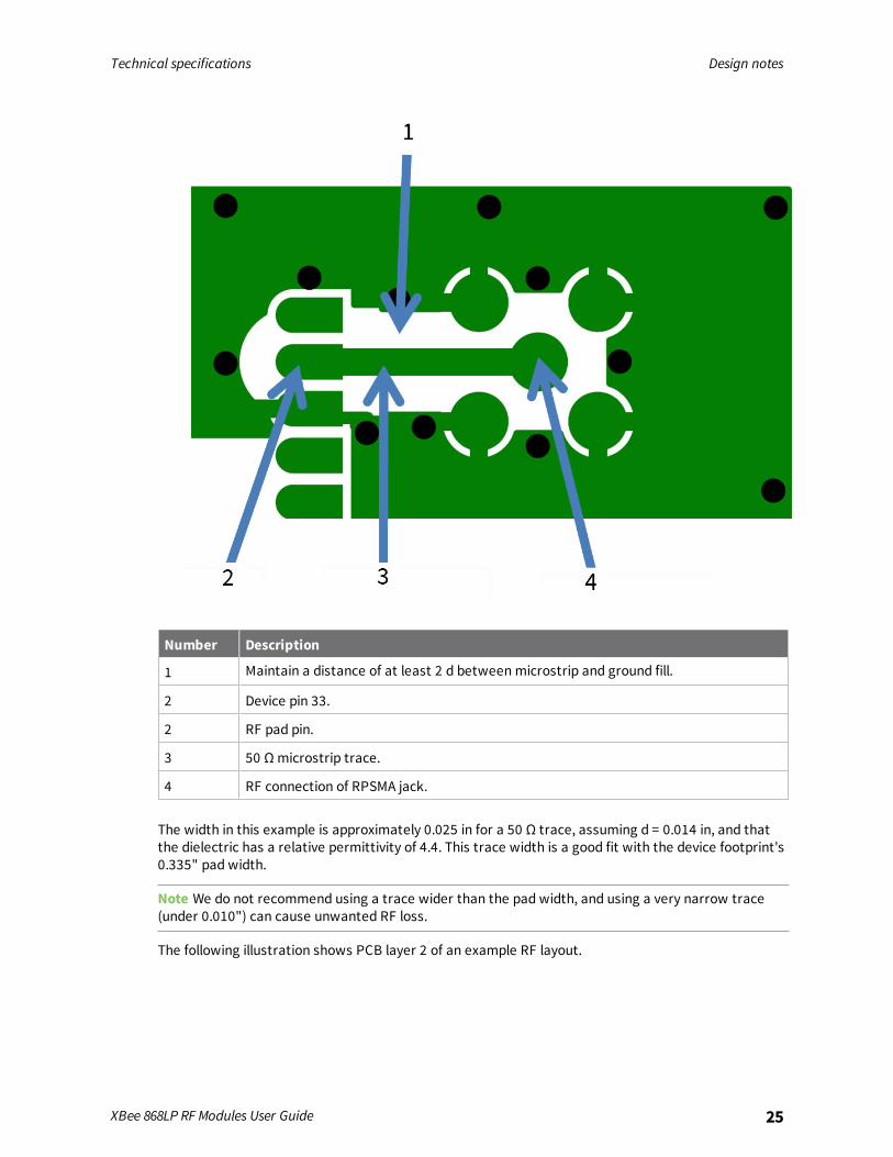
Implementing these design suggestions helps ensure that the RF pad device performs to itsspecifications.The following figures show a layout example of a host PCB that connects an RF pad device to a rightangle, through-hole RPSMA jack.
Technical specifications Design notes
XBee 868LP RF Modules User Guide 25
Number Description
1 Maintain a distance of at least 2 d betweenmicrostrip and ground fill.
2 Device pin 33.
2 RF pad pin.
3 50 Ω microstrip trace.
4 RF connection of RPSMA jack.
The width in this example is approximately 0.025 in for a 50 Ω trace, assuming d = 0.014 in, and thatthe dielectric has a relative permittivity of 4.4. This trace width is a good fit with the device footprint's0.335" pad width.
Note We do not recommend using a trace wider than the pad width, and using a very narrow trace(under 0.010") can cause unwanted RF loss.
The following illustration shows PCB layer 2 of an example RF layout.

Technical specifications Design notes
XBee 868LP RF Modules User Guide 26
Number Description
1 Use multiple vias to help eliminate ground variations.
2 Put a solid ground plane under RF trace to achieve the desired impedance.
Module operation for the programmable variantThe modules with the programmable option have a secondary processor with 32k of flash and 2k ofRAM. This allows module integrators to put custom code on the XBee module to fit their own uniqueneeds. The DIN, DOUT, RTS, CTS, and RESET lines are intercepted by the secondary processor to allowit to be in control of the data transmitted and received. All other lines are in parallel and can becontrolled by either the internal microcontroller or the MC9SO8QE micro; see the block diagram inOperation for details. The internal microcontroller by default has control of certain lines. The internalmicrocontroller can release these lines by sending the proper command(s) to disable the desired DIOline(s). For more information about commands, see AT commands.For the secondary processor to sample with ADCs, the XBee must be connected to a referencevoltage.Digi provides a bootloader that can take care of programming the processor over-the-air or throughthe serial interface. This means that over-the-air updates can be supported through an XMODEMprotocol. The processor can also be programmed and debugged through a one wire interface BKGD .

Technical specifications Design notes
XBee 868LP RF Modules User Guide 27
Programmable XBee SDKThe XBee Programmable module is equipped with a NXP MC9S08QE32 application processor. Thisapplication processor comes with a supplied bootloader. To interface your application code running onthis processor to the XBee Programmable module's supplied bootloader, use the Programmable XBeeSDK.To use the SDK, you must also download CodeWarrior. The download links are:
n CodeWarrior IDE: http://ftp1.digi.com/support/sampleapplications/40003004_B.exe
n Programmable XBee SDK: http://ftp1.digi.com/support/sampleapplications/40003003_D.exe
If these revisions change, search for the part number on Digi’s website. For example, search for40003003.Install the IDE first, and then install the SDK.The documentation for the Programmable XBee SDK is built into the SDK, so the Getting Started guideappears when you open CodeWarrior.
Get started
The XBee 868LP RF Modules support low-power, peer-to-peer or wireless mesh networks for Europe(868 MHz). The XBee 868LP RF Modules provide reliable delivery of data between remote devices.This guide shows you how to set up a mesh network using the DigiMesh protocol, send data betweendevices, and adjust XBee 868LP RF Module settings.
Note For more information about DigiMesh protocol and features, see DigiMesh networking.
This guide covers the following tasks and features:
Set up the devices 29Do more with your XBee modules 46Learn more about XBee module features 58Troubleshooting 60
XBee 868LP RF Modules User Guide 28

Get started Set up the devices
XBee 868LP RF Modules User Guide 29
Set up the devices
Before you beginTo get started with your XBee RF module development kit, verify that your kit has all of thecomponents and that you meet the system requirements.
Verify kit contentsThe XBee 868LP RF Module development kit contains the following components:
XBeeU.FL module (3)
XBeedevelopmentboard (3)
USB cable (2)
Power supply(2)
Set of powersupply adapters(2)

Get started Set up the devices
XBee 868LP RF Modules User Guide 30
Antenna U.FL (3)
Gather required materialsTo complete the steps in this guide, you need the following items:
Item Description
Computer Operating systems:n Windows Vista/7/8 (32-bit or 64-bit versions)
n Mac OS X v10.6 and higher versions (64-bit only)
n Linux with KDE or GNOME window managers (32-bit or 64-bit versions)System requirements:
n HDD space: 500 MB minimum, 1GB recommended
n RAM memory: 2 GB minimum, 4 GB recommended
n CPU: Dual-core processor minimum, Quad-core processor recommendedUSB ports:
n Three available USB ports for the XBee/XBee-PRO DigiMesh 2.4 development kit
n Two available USB ports for the XBee 868LP development kit
Note Only one computer is required to follow along with the steps in this guide.However, you can use two or more computers—one for each XBee module. For rangetesting, we recommend a laptop.
XCTUsoftware
Version 6.1.3 or later. See Download and install XCTU.
USBdrivers
Windows Vista and later: USB drivers automatically install through plug-and-play.Windows XP and earlier: You need to download the driver software.See Optional: Manually install USB drivers.
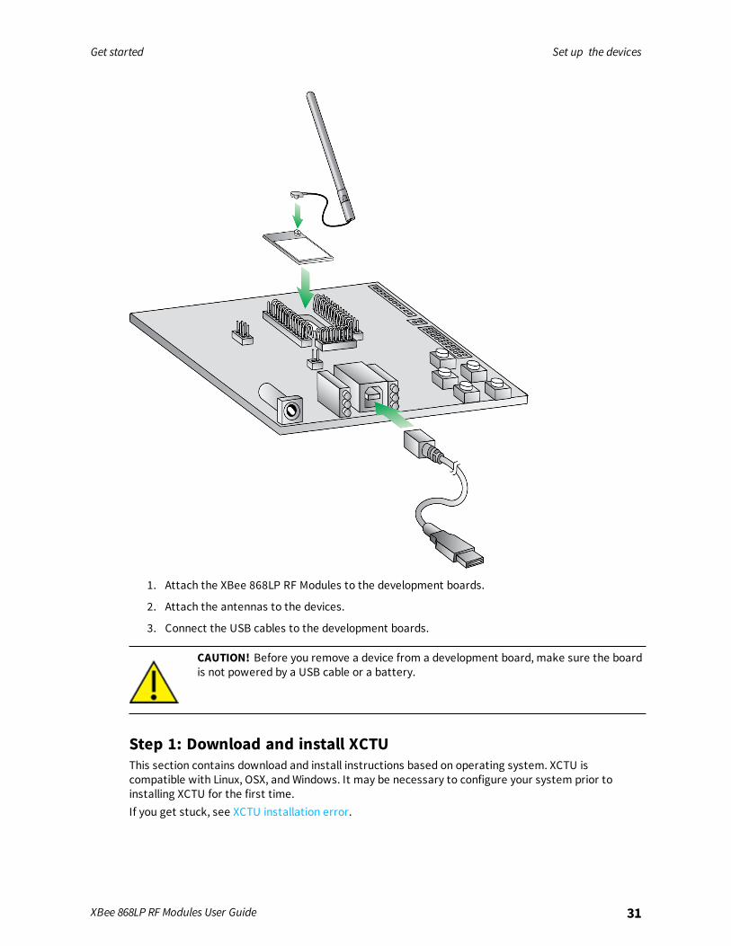
Connect the hardwareThe following illustration shows you how to assemble the hardware components of the developmentkit.
Get started Set up the devices
XBee 868LP RF Modules User Guide 31
1. Attach the XBee 868LP RF Modules to the development boards.
2. Attach the antennas to the devices.
3. Connect the USB cables to the development boards.
CAUTION! Before you remove a device from a development board, make sure the boardis not powered by a USB cable or a battery.
Step 1: Download and install XCTUThis section contains download and install instructions based on operating system. XCTU iscompatible with Linux, OSX, andWindows. It may be necessary to configure your system prior toinstalling XCTU for the first time.If you get stuck, see XCTU installation error.

Get started Set up the devices
XBee 868LP RF Modules User Guide 32
Download and install XCTU - WindowsFollow the steps below to download and install XCTU on your computer.
1. Go to www.digi.com/xctu.
2. Click Download.
3. Under Download XCTU, click the Windows installer link.
4. Once the download is complete, run the executable file and follow the steps in the XCTU SetupWizard.
Once installation is complete, a “What’s new” dialog appears where you can review the newXCTU features.
Download and install XCTU - LinuxBy default, access to the serial and USB ports in Linux is restricted to root and dialout group users. Toaccess your XBee devices and use XCTU to communicate with them, it is mandatory that your Linuxuser belongs to this group. To add your Linux user to the dialout group:
1. Open a terminal console.
2. Execute the following command where <user> is the user you want to add to the dialout group:
sudo usermod -a -G dialout <user>
3. Log out and log in again with your user in the system.
4. Go to www.digi.com/xctu.
5. Click Download.
6. Under Download XCTU, click the Linux installer link.
7. Once the download is complete, run the executable file and follow the steps in the XCTU SetupWizard.
Once installation is complete, a “What’s new” dialog appears where you can review the newXCTU features.
Download and install XCTU - OSXOSX version 10.8 (Mountain Lion) and greater only allows you to install applications downloaded fromthe Apple Store. To install XCTU, you must temporarily disable this setting. Follow these steps toenable installation of "unsigned" software:
1. Click the Apple icon in the top-left corner of your screen and choose System Preferences.
2. Click the Security & Privacy icon.
3. To edit security settings, click the padlock icon in the bottom left of the window.
4. Enter your Mac credentials and click Unlock. The Allow applications downloaded from dialogappears.
5. Click the Anywhere radio button and, in the confirmation window, click Allow FromAnywhere.
Get started Set up the devices
XBee 868LP RF Modules User Guide 33
Note We recommend you set this option back toMac App Store or Mac App Store and identifieddevelopers once you have finished installing XCTU.
6. Go to www.digi.com/xctu.
7. Click Download.
8. Under Download XCTU, click the OSX installer link.
9. Once the download is complete, unzip and run the executable file and follow the steps in theXCTU SetupWizard.
Once installation is complete, a “What’s new” dialog appears where you can review the newXCTU features.
Optional: Install XCTU updatesWhen you start XCTU, you may be notified about software updates. You should always run the latestversion of XCTU.
1. When a new version is available, a popup window appears in the bottom-right corner of XCTU.
2. Click on that window and follow the prompts to proceed with the update.
You can also check for updates andmanually update the tool by clicking Help > Check for XCTUUpdates.
Optional: Manually install USB driversWhen you connect the XBee board to your computer for the first time, drivers are automaticallyinstalled. You can also install device drivers manually:
1. Download and install the appropriate USB drivers from the Digi Support Site.
2. Choose your operating system.
3. Download and run the file.
4. Follow the steps in the installation wizard.
Step 2: Set up your first wireless connectionThis section shows you how to configure two XBee modules in AT (transparent) mode. The XBeemodule passes information along exactly as it receives it. All serial data received by the XBee moduleis sent wirelessly to a remote destination XBee module.If you get stuck, see Troubleshooting.
Add devices to XCTUThese instructions show you how to add two devices to XCTU. However, you can use theseinstructions to add any number of devices.
1. Connect two XBee 868LP RF Modules to your computer using the USB cables.
Tip Connect the two shorter range XBee modules instead of the longer range XBee-PROmodules. This will make it easier to set up a mesh network. See Connect the hardware.
2. Launch XCTU .

Get started Set up the devices
XBee 868LP RF Modules User Guide 34
3. Click the Configuration working modes button .
4. Click the Discover radio modules button .
5. In the Discover radio devices dialog, select the serial ports where you want to look for devicesand click Next.
6. In the Set port parameters window, maintain the default values and click Finish.
As XCTU locates devices, they appear in the Discovering radio modules dialog box.
7. Click Add selected devices once the discovery process has finished.
You should see something like this in the Radio Modules section:
Configure the first two devices in Transparent modeTo transmit data wirelessly between your XBee devices, configure them to be in the same network.
Tip To locate a device, select it in XCTU and click the Read radio settings button . The Rx and TxLED lights on its development board blink green and yellow.
Set up the first XBee device (XBEE_A)1. Select the first XBee device.

Get started Set up the devices
XBee 868LP RF Modules User Guide 35
2. Click the Load default firmware settings button .
Tip In the following steps, type parameter letters in the Search box to
quickly find a parameter.
3. Configure the following parameters:
ID: 2015DH: 0013A200DL: SL of XBEE_B (Enter the last eight characters of the MAC address for XBEE_B. Or selectXBEE_B and find its SL value.)NI: XBEE_A
4. Click the Write radio settings button .
Set up the second XBee device (XBEE_B)
1. Configure the following parameters:
ID: 2015DH: 0013A200DL: SL of XBEE_A (Enter the last eight characters of the MAC address for XBEE_A. Or selectXBEE_A and find its SL value.)NI: XBEE_B
2. Click the Write radio settings button .
After you write the radio settings for the XBee devices, their names appear in the Radio Modulesarea.
For more information about the parameters, see the following table:
Parameter XBEE_A XBEE_B Effect
ID 2015 2015 Defines the network that a device will attach to. This must bethe same for all devices in your network.
Get started Set up the devices
XBee 868LP RF Modules User Guide 36
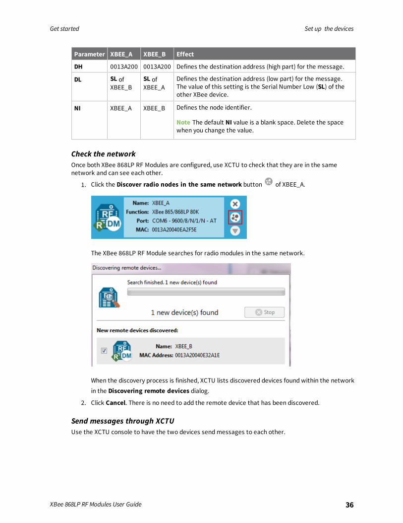
Parameter XBEE_A XBEE_B Effect
DH 0013A200 0013A200 Defines the destination address (high part) for the message.
DL SL ofXBEE_B
SL ofXBEE_A
Defines the destination address (low part) for the message.The value of this setting is the Serial Number Low (SL) of theother XBee device.
NI XBEE_A XBEE_B Defines the node identifier.
Note The default NI value is a blank space. Delete the spacewhen you change the value.
Check the networkOnce both XBee 868LP RF Modules are configured, use XCTU to check that they are in the samenetwork and can see each other.
1. Click the Discover radio nodes in the same network button of XBEE_A.
The XBee 868LP RF Module searches for radio modules in the same network.
When the discovery process is finished, XCTU lists discovered devices found within the networkin the Discovering remote devices dialog.
2. Click Cancel. There is no need to add the remote device that has been discovered.
Send messages through XCTUUse the XCTU console to have the two devices sendmessages to each other.
Get started Set up the devices
XBee 868LP RF Modules User Guide 37
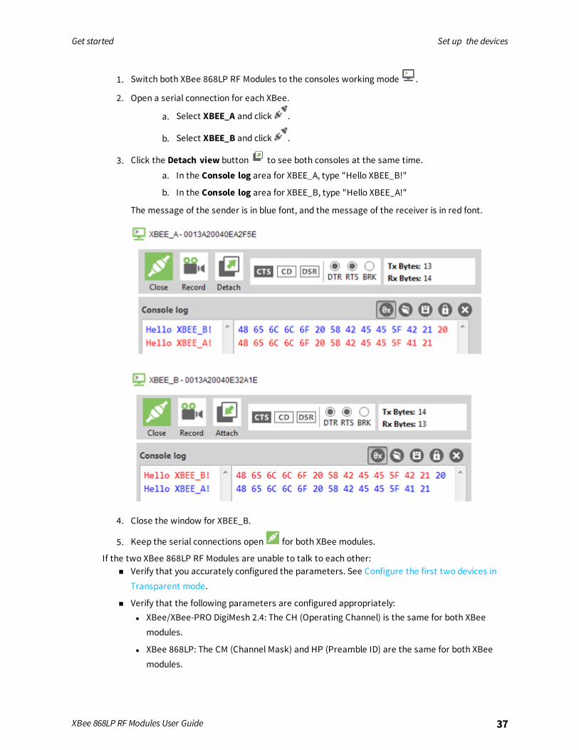
1. Switch both XBee 868LP RF Modules to the consoles working mode .
2. Open a serial connection for each XBee.
a. Select XBEE_A and click .
b. Select XBEE_B and click .
3. Click the Detach view button to see both consoles at the same time.
a. In the Console log area for XBEE_A, type "Hello XBEE_B!"
b. In the Console log area for XBEE_B, type "Hello XBEE_A!"
The message of the sender is in blue font, and the message of the receiver is in red font.
4. Close the window for XBEE_B.
5. Keep the serial connections open for both XBee modules.
If the two XBee 868LP RF Modules are unable to talk to each other:n Verify that you accurately configured the parameters. See Configure the first two devices in
Transparent mode.
n Verify that the following parameters are configured appropriately:l XBee/XBee-PRO DigiMesh 2.4: The CH (Operating Channel) is the same for both XBee
modules.
l XBee 868LP: The CM (Channel Mask) and HP (Preamble ID) are the same for both XBeemodules.

Get started Set up the devices
XBee 868LP RF Modules User Guide 38
Step 3: Create a mesh networkThis section describes how to add a third XBee module to create a mesh network. Establish a meshnetwork any time you want to create a network that is larger than the range of each individual radio.In these instructions, you first connect a loopback jumper to an XBee module in preparation fortesting your network.If you get stuck, see Troubleshooting.
Connect a loopback jumper to an XBee deviceConnecting a loopback jumper to an XBee device lets you send a message to another XBee device andhave the message loop back to the sender.
1. Connect the loopback jumper on XBEE_B so it bridges the two pins on its development board.
2. In the XBEE_A console, click the Clear session button to clear your previous conversation.
3. Type Hello!
Each character loops back in the XBEE_A console log, which indicates that XBEE_A successfullysent the message to XBEE_B.
You are now ready to use the loopback jumper to help you test a mesh network consisting ofthree XBee devices.
Get started Set up the devices
XBee 868LP RF Modules User Guide 39
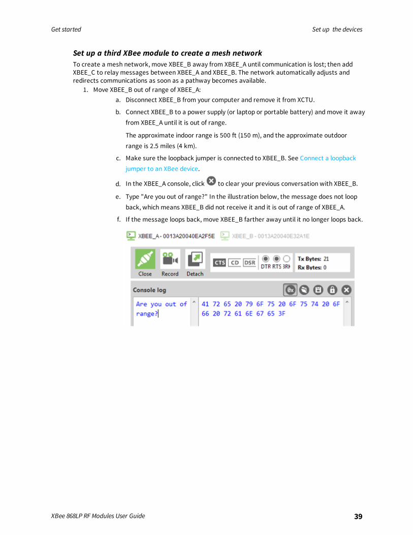
Set up a third XBee module to create a mesh networkTo create a mesh network, move XBEE_B away from XBEE_A until communication is lost; then addXBEE_C to relay messages between XBEE_A and XBEE_B. The network automatically adjusts andredirects communications as soon as a pathway becomes available.
1. Move XBEE_B out of range of XBEE_A:a. Disconnect XBEE_B from your computer and remove it from XCTU.
b. Connect XBEE_B to a power supply (or laptop or portable battery) andmove it awayfrom XBEE_A until it is out of range.
The approximate indoor range is 500 ft (150 m), and the approximate outdoorrange is 2.5 miles (4 km).
c. Make sure the loopback jumper is connected to XBEE_B. See Connect a loopbackjumper to an XBee device.
d. In the XBEE_A console, click to clear your previous conversation with XBEE_B.
e. Type "Are you out of range?" In the illustration below, the message does not loopback, which means XBEE_B did not receive it and it is out of range of XBEE_A.
f. If the message loops back, move XBEE_B farther away until it no longer loops back.
Get started Set up the devices
XBee 868LP RF Modules User Guide 40
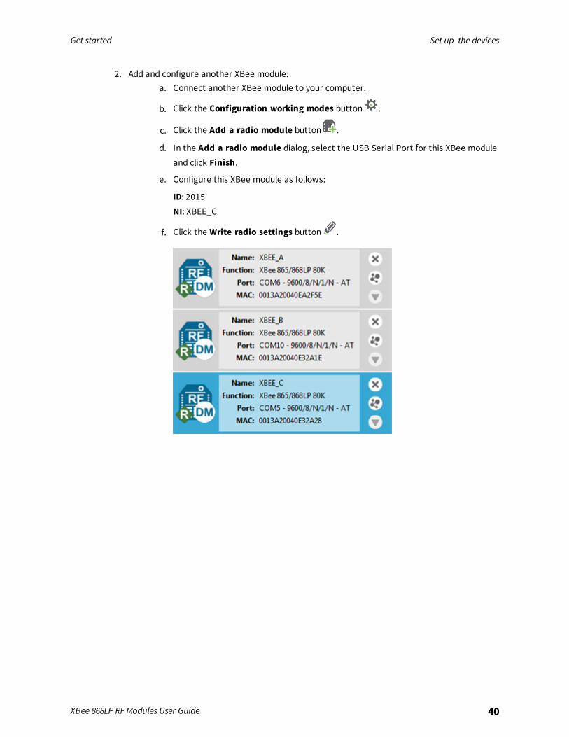
2. Add and configure another XBee module:a. Connect another XBee module to your computer.
b. Click the Configuration working modes button .
c. Click the Add a radio module button .
d. In the Add a radio module dialog, select the USB Serial Port for this XBee moduleand click Finish.
e. Configure this XBee module as follows:
ID: 2015NI: XBEE_C
f. Click the Write radio settings button .
Get started Set up the devices
XBee 868LP RF Modules User Guide 41
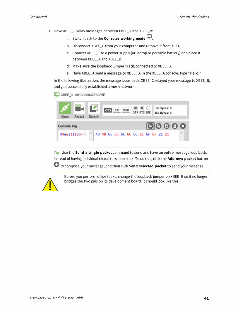
3. Have XBEE_C relay messages between XBEE_A and XBEE_B:
a. Switch back to the Consoles working mode .
b. Disconnect XBEE_C from your computer and remove it from XCTU.
c. Connect XBEE_C to a power supply (or laptop or portable battery) and place itbetween XBEE_A and XBEE_B.
d. Make sure the loopback jumper is still connected to XBEE_B.
e. Have XBEE_A send a message to XBEE_B. In the XBEE_A console, type "Hello!"
In the following illustration, the message loops back. XBEE_C relayed your message to XBEE_B,and you successfully established a mesh network.
Tip Use the Send a single packet command to send and have an entire message loop back,instead of having individual characters loop back. To do this, click the Add new packet button
to compose your message, and then click Send selected packet to send your message.
Before you perform other tasks, change the loopback jumper on XBEE_B so it no longerbridges the two pins on its development board. It should look like this:
Get started Set up the devices
XBee 868LP RF Modules User Guide 42
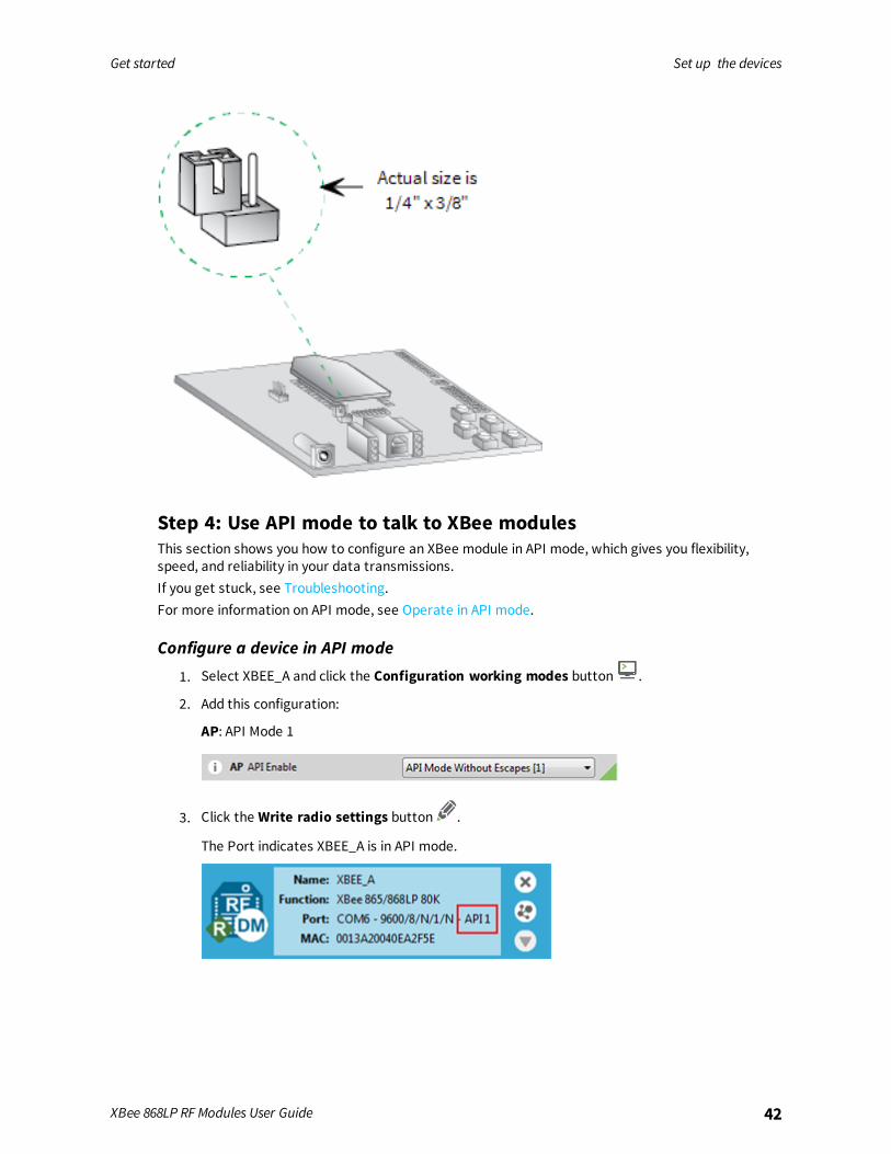
Step 4: Use API mode to talk to XBee modulesThis section shows you how to configure an XBee module in API mode, which gives you flexibility,speed, and reliability in your data transmissions.If you get stuck, see Troubleshooting.For more information on API mode, see Operate in API mode.
Configure a device in API mode
1. Select XBEE_A and click the Configuration working modes button .
2. Add this configuration:
AP: API Mode 1
3. Click the Write radio settings button .
The Port indicates XBEE_A is in API mode.
Get started Set up the devices
XBee 868LP RF Modules User Guide 43
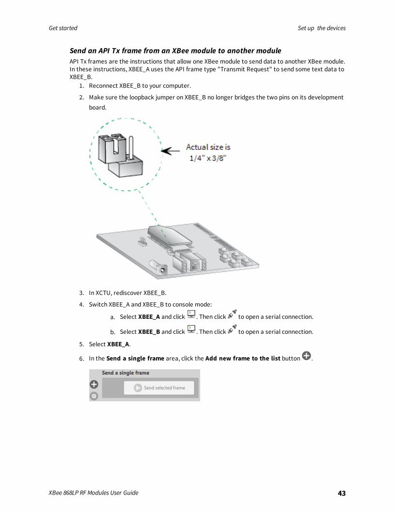
Send an API Tx frame from an XBee module to another moduleAPI Tx frames are the instructions that allow one XBee module to send data to another XBee module.In these instructions, XBEE_A uses the API frame type "Transmit Request" to send some text data toXBEE_B.
1. Reconnect XBEE_B to your computer.
2. Make sure the loopback jumper on XBEE_B no longer bridges the two pins on its developmentboard.
3. In XCTU, rediscover XBEE_B.
4. Switch XBEE_A and XBEE_B to console mode:
a. Select XBEE_A and click . Then click to open a serial connection.
b. Select XBEE_B and click . Then click to open a serial connection.
5. Select XBEE_A.
6. In the Send a single frame area, click the Add new frame to the list button .
Get started Set up the devices
XBee 868LP RF Modules User Guide 44
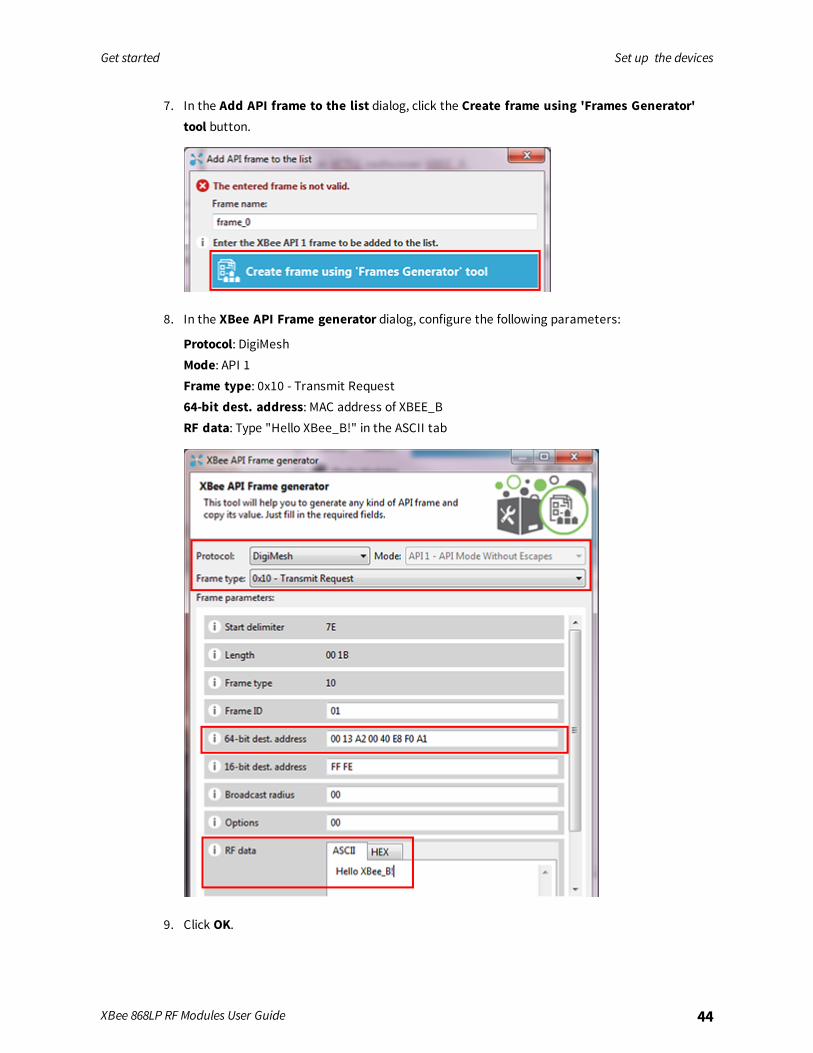
7. In the Add API frame to the list dialog, click the Create frame using 'Frames Generator'tool button.
8. In the XBee API Frame generator dialog, configure the following parameters:
Protocol: DigiMeshMode: API 1Frame type: 0x10 - Transmit Request64-bit dest. address: MAC address of XBEE_BRF data: Type "Hello XBee_B!" in the ASCII tab
9. Click OK.
Get started Set up the devices
XBee 868LP RF Modules User Guide 45
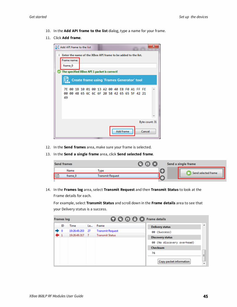
10. In the Add API frame to the list dialog, type a name for your frame.
11. Click Add frame.
12. In the Send frames area, make sure your frame is selected.
13. In the Send a single frame area, click Send selected frame.
14. In the Frames log area, select Transmit Request and then Transmit Status to look at theFrame details for each.
For example, select Transmit Status and scroll down in the Frame details area to see thatyour Delivery status is a success.
Get started Do more with your XBee modules
XBee 868LP RF Modules User Guide 46
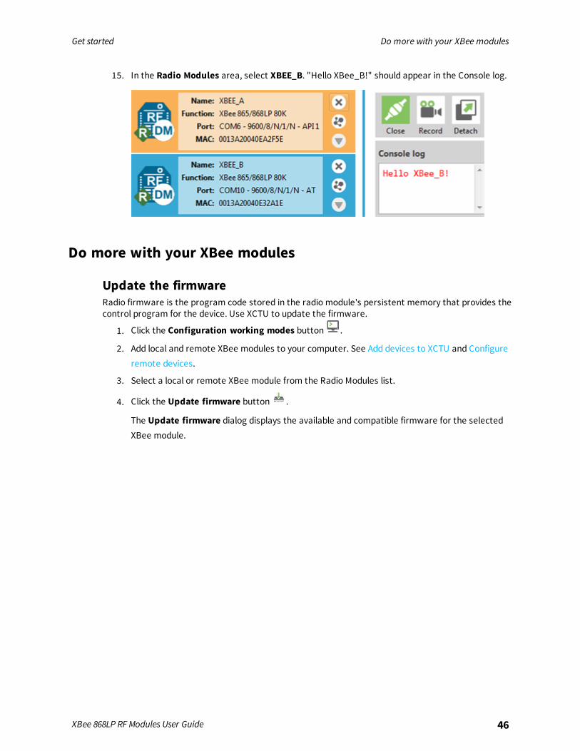
15. In the Radio Modules area, select XBEE_B. "Hello XBee_B!" should appear in the Console log.
Do more with your XBee modules
Update the firmwareRadio firmware is the program code stored in the radio module's persistent memory that provides thecontrol program for the device. Use XCTU to update the firmware.
1. Click the Configuration working modes button .
2. Add local and remote XBee modules to your computer. See Add devices to XCTU and Configureremote devices.
3. Select a local or remote XBee module from the Radio Modules list.
4. Click the Update firmware button .
The Update firmware dialog displays the available and compatible firmware for the selectedXBee module.
Get started Do more with your XBee modules
XBee 868LP RF Modules User Guide 47
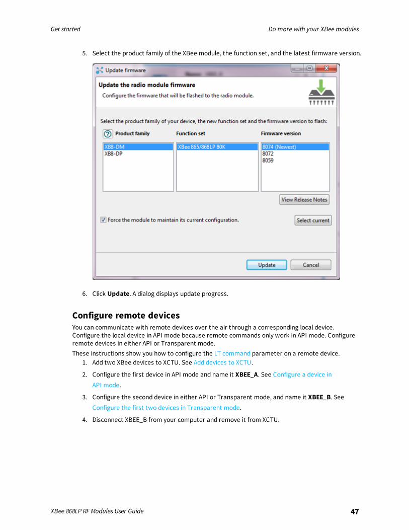
5. Select the product family of the XBee module, the function set, and the latest firmware version.
6. Click Update. A dialog displays update progress.
Configure remote devicesYou can communicate with remote devices over the air through a corresponding local device.Configure the local device in API mode because remote commands only work in API mode. Configureremote devices in either API or Transparent mode.These instructions show you how to configure the LT command parameter on a remote device.
1. Add two XBee devices to XCTU. See Add devices to XCTU.
2. Configure the first device in API mode and name it XBEE_A. See Configure a device inAPI mode.
3. Configure the second device in either API or Transparent mode, and name it XBEE_B. SeeConfigure the first two devices in Transparent mode.
4. Disconnect XBEE_B from your computer and remove it from XCTU.
Get started Do more with your XBee modules
XBee 868LP RF Modules User Guide 48
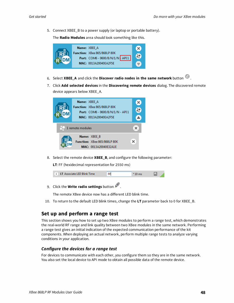
5. Connect XBEE_B to a power supply (or laptop or portable battery).
The Radio Modules area should look something like this.
6. Select XBEE_A and click the Discover radio nodes in the same network button .
7. Click Add selected devices in the Discovering remote devices dialog. The discovered remotedevice appears below XBEE_A.
8. Select the remote device XBEE_B, and configure the following parameter:
LT: FF (hexidecimal representation for 2550 ms)
9. Click the Write radio settings button .
The remote XBee device now has a different LED blink time.
10. To return to the default LED blink times, change the LT parameter back to 0 for XBEE_B.
Set up and perform a range testThis section shows you how to set up two XBee modules to perform a range test, which demonstratesthe real-world RF range and link quality between two XBee modules in the same network. Performinga range test gives an initial indication of the expected communication performance of the kitcomponents. When deploying an actual network, perform multiple range tests to analyze varyingconditions in your application.
Configure the devices for a range testFor devices to communicate with each other, you configure them so they are in the same network.You also set the local device to API mode to obtain all possible data of the remote device.
Get started Do more with your XBee modules
XBee 868LP RF Modules User Guide 49
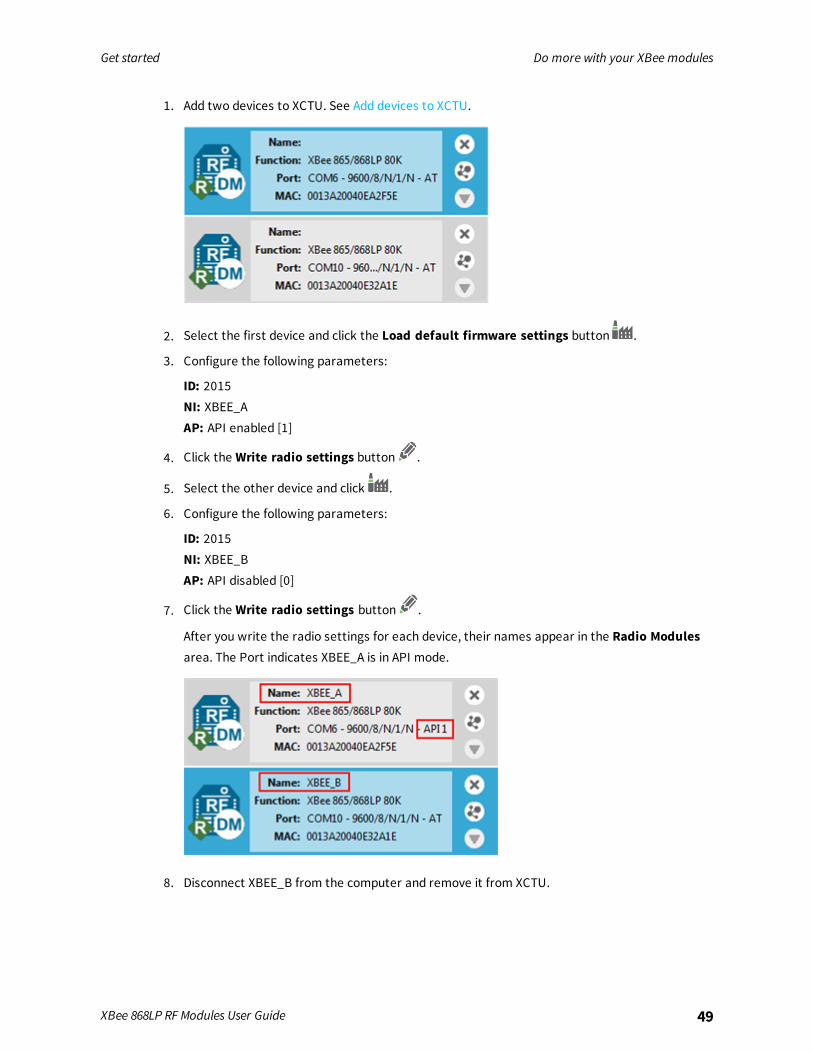
1. Add two devices to XCTU. See Add devices to XCTU.
2. Select the first device and click the Load default firmware settings button .
3. Configure the following parameters:
ID: 2015NI: XBEE_AAP: API enabled [1]
4. Click the Write radio settings button .
5. Select the other device and click .
6. Configure the following parameters:
ID: 2015NI: XBEE_BAP: API disabled [0]
7. Click the Write radio settings button .
After you write the radio settings for each device, their names appear in the Radio Modulesarea. The Port indicates XBEE_A is in API mode.
8. Disconnect XBEE_B from the computer and remove it from XCTU.

Get started Do more with your XBee modules
XBee 868LP RF Modules User Guide 50
9. Connect XBEE_B to a power supply (or laptop or portable battery) andmove it away fromXBEE_A to the desired location for the range test.
The approximate indoor range is 500 ft (150 m), and the approximate outdoor range is 2.5miles (4 km).
Perform a range testThese instructions show you how to use the loopback cluster (0x12) when performing a range test.The benefit of using this type of range test is you don't have to close the loopback jumper of theremote module and the module can work in any operating mode.
1. In XCTU, open the Tools menu and select the Range Test option.
The Radio Range Test window opens. Your local device appears on the left side of the DeviceSelection area.
2. Select XBEE_A and click the Discover remote devices button .
The discovery of remote devices starts. When the discovery process finishes, the other device(XBEE_B) appears in the Discovering remote devices dialog.
3. Click Add selected devices.
4. Select XBEE_B from the Discovered device drop-downmenu in the Device Selection area.
5. For Range Test type, select Cluster ID 0x12.
6. Click the Start Range Test button .
7. If a notification dialog asks you to close the loopback jumper in the remote device, click OK.
Get started Do more with your XBee modules
XBee 868LP RF Modules User Guide 51
8. Test the signal interference by doing one of the following:n Place your hands over one of the XBee modules.
n Block line-of-sight with your body.
n Place a metal box over an XBee module.
n Move the remote XBee module to a different room or floor of the building.
The Received Signal Strength Indicator (RSSI) value will decrease and some packets may evenbe lost.
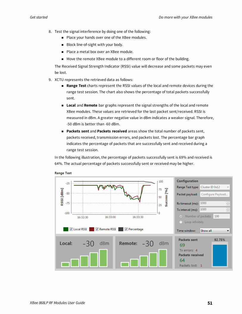
9. XCTU represents the retrieved data as follows:n Range Test charts represent the RSSI values of the local and remote devices during the
range test session. The chart also shows the percentage of total packets successfullysent.
n Local and Remote bar graphs represent the signal strengths of the local and remoteXBee modules. These values are retrieved for the last packet sent/received. RSSI ismeasured in dBm. A greater negative value in dBm indicates a weaker signal. Therefore,-50 dBm is better than -60 dBm.
n Packets sent and Packets received areas show the total number of packets sent,packets received, transmission errors, and packets lost. The percentage bar graphindicates the percentage of packets that are successfully sent and received during arange test session.
In the following illustration, the percentage of packets successfully sent is 69% and received is64%. The actual percentage of packets successfully sent or receivedmay be higher.

Get started Do more with your XBee modules
XBee 868LP RF Modules User Guide 52
10. Click the Stop Range Test button to stop the process at any time.
11. When you have completed the range test, remove the remote XBee modules from XCTU by
clicking the Remove the list of remote modules button .
Configure basic synchronous sleep supportThis section shows you how to extend the battery life of an XBee device and demonstrates how aDigiMesh network handles messages when nodes are synchronously sleeping. You will configure oneof the devices as a sleep support node and the other two as synchronous cyclic sleep nodes.The sleep support XBee device is always awake and can receive serial or over-the-air data at any time,whereas the synchronized sleeping devices cannot send or receive data during their sleep periods.When receivers are asleep, the messages are buffered and forwarded to their destination once theyhave woken up. In either case, XBee devices can only receive data up to the capacity of the inputbuffer.
Configure the sleep coordinator for synchronous sleep supportThese instructions show you how to configure XBEE_A as the preferred sleep coordinator so it staysawake while the other XBee devices sleep. You then configure XBEE_B and XBEE_C so one of themassumes the role of sleep coordinator when you disconnect XBEE_A. This allows the network toremain in sync with minimal impact on battery life.
Note If you have only two USB cables: After you configure XBEE_B, disconnect it from your computerand remove it from XCTU. Then connect it to a power supply (or laptop or portable battery). Next, usethe available USB cable to connect and configure XBEE_C.
1. Add three devices to XCTU. See Add devices to XCTU.
2. For each device, click the Load default firmware settings button and then the Write
radio settings button .
Get started Do more with your XBee modules
XBee 868LP RF Modules User Guide 53
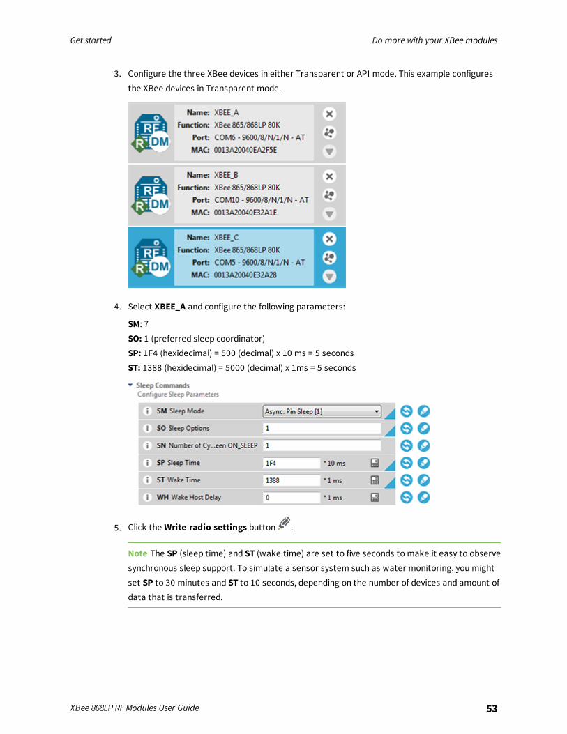
3. Configure the three XBee devices in either Transparent or API mode. This example configuresthe XBee devices in Transparent mode.
4. Select XBEE_A and configure the following parameters:
SM: 7SO: 1 (preferred sleep coordinator)SP: 1F4 (hexidecimal) = 500 (decimal) x 10 ms = 5 secondsST: 1388 (hexidecimal) = 5000 (decimal) x 1ms = 5 seconds
5. Click the Write radio settings button .
Note The SP (sleep time) and ST (wake time) are set to five seconds to make it easy to observesynchronous sleep support. To simulate a sensor system such as water monitoring, you mightset SP to 30 minutes and ST to 10 seconds, depending on the number of devices and amount ofdata that is transferred.

Get started Do more with your XBee modules
XBee 868LP RF Modules User Guide 54
6. Select XBEE_B and configure the following sleep parameters:
SM: 8SO: 0 (allows the XBee module to take over the role of sleep coordinator if the preferred sleepcoordinator fails)SP: 1E (hexidecimal) = 30 (decimal) x 10 ms = 300 msST: BB8 (hexidecimal) = 3000 (decimal) x 1 ms = 3 seconds
7. Click the Write radio settings button .
8. Configure the sleep parameters for XBEE_C as you did for XBEE_B. Click when you are
done.
Note Once XBEE_B and XBEE_C sync up to the network, their wake and sleep times arecontrolled by the OS andOW settings on the sleep support node (XBEE_A). If you want tochange the wake and sleep times, change the SP and ST values for XBEE_A.
9. The LED lights on the three devices appear as follows:
XBee module Wake period Sleep period
XBEE_A (sleep coordinator) Flashing red light Solid red light
XBEE_B and XBEE_C Flashing red light No light
10. Change the role of sleep coordinator:a. Disconnect XBEE_A from your computer.
b. Observe XBEE_B or XBEE_C taking over the role of sleep coordinator by looking atthe behavior of the LED lights. It could take three cycles for the new sleepcoordinator to take effect.
c. Re-connect XBEE_A to your computer.
d. Observe XBEE_A re-assuming the role of sleep coordinator.
Get started Do more with your XBee modules
XBee 868LP RF Modules User Guide 55
Note If a device gets out of sync, it goes through a re-synchronization process.
Observe flow control during synchronous sleep supportThese instructions demonstrate the importance of observing flow control while XBees are sendingand receiving data during synchronous sleep support. Flow control is the process used by a device toinform another device to stop sending data in order to prevent data loss.
1. Click the Consoles working mode button .
2. Select XBEE_A (the preferred sleep coordinator), and click to open a serial connection.
3. Select XBEE_B and click .
4. Click the Detach view button to see both consoles at the same time.
Get started Do more with your XBee modules
XBee 868LP RF Modules User Guide 56
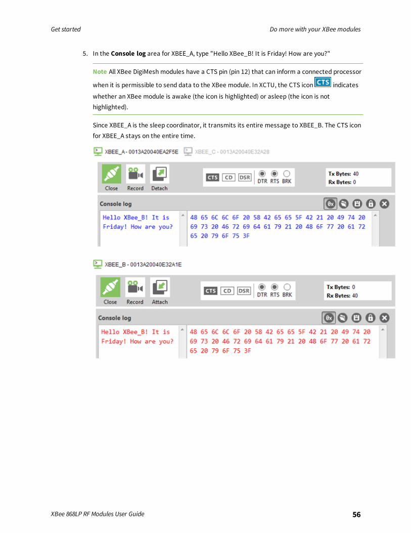
5. In the Console log area for XBEE_A, type "Hello XBee_B! It is Friday! How are you?"
Note All XBee DigiMesh modules have a CTS pin (pin 12) that can inform a connected processor
when it is permissible to send data to the XBee module. In XCTU, the CTS icon indicates
whether an XBee module is awake (the icon is highlighted) or asleep (the icon is nothighlighted).
Since XBEE_A is the sleep coordinator, it transmits its entire message to XBEE_B. The CTS iconfor XBEE_A stays on the entire time.

Get started Do more with your XBee modules
XBee 868LP RF Modules User Guide 57
6. In the Console log area for XBEE_B, type "Hello XBee_A! It is Friday! How are you?"
Since XBEE_B is a synchronized sleeping module, it only transmits the part of the message thatis typed while it is awake. In the illustration below, it was only able to transmit "Hello XBee_A!" The CTS icon for XBEE_B turned off after this part of the message was typed.
7. To disconnect, click the Close serial connection button for each console.
Set up basic encryption for an XBee networkThe information transmitted in an XBee network sometimes needs to be protected. For example, anXBee network transferring financial information must be carefully protected against external agents.These instructions show you how to configure XBee 868LP RF Modules for secure communication viaencryption keys.
Note You can use encryption for devices that have been configured for either Transparent or APImode.

Get started Learn more about XBee module features
XBee 868LP RF Modules User Guide 58
1. Add two XBee modules to XCTU. See Add devices to XCTU.
2. Configure the XBee modules so they can talk to each other. See Configure the first two devicesin Transparent mode.
3. Name your two XBee modules XBee_A and XBee_B.
4. Select XBee_A and configure the following parameters:
EE: Set the AES Encryption Enable parameter to 1.KY: Set the AES Encryption Key parameter to a 32 hexadecimal character string. Example:11111222223333344444555556666677
5. Click the Write radio settings button .
6. Configure the parameters for XBEE_B as you did for XBEE_A, and then click .
7. Send a secure message between XBee_A and XBee_B. See Sendmessages through XCTU.
Note If you addmore devices, give them the same encryption key so they can communicate with theother XBee devices.
8. To return to the encryption disabled setting, change the EE parameter back to 0 for XBEE_Aand XBEE_B.
Learn more about XBee module featuresFor more information about XBee 868LP RF modules, see the XBee 868LP RF Modules User Guide. Youcan find this guide on the Digi Support site.
Unicast versus broadcast transmissionsAn XBee module can communicate with multiple devices or with just one device:

Get started Learn more about XBee module features
XBee 868LP RF Modules User Guide 59
n Broadcast transmissions are sent to many or all XBee modules in the network.
n Unicast transmissions route wireless data from one XBee module to another specific XBeemodule.
Broadcast transmissionA broadcast transmission transmits the same data to all nodes on the network. These transmissionsare propagated throughout the entire network so that all possible nodes receive the transmission.An example of broadcast communication is a television station.
Unicast transmissionA unicast transmission sends messages to a single node on the network that is identified by a unique64-bit address. The destination XBee module could be an immediate neighbor of the sender, or beseveral hops away.An example of a unicast communication is a telephone call between two people.For more information, see Data transmission and routing.
Analog inputs and digital inputs and outputsAll XBee modules have a set of pins that can be used to connect sensors or actuators and configurethem for specific behavior. Each XBee module has the capability to directly gather sensor data andtransmit it without the use of an external microcontroller.With these pins you can, for example, turn on a light by sending information to an XBee moduleconnected to an actuator, or measure the outside temperature by obtaining data from a temperaturesensor attached to your XBee module.
Sleep modesPutting XBee devices into a temporary sleep state preserves battery life when using wirelessnetworks. DigiMesh devices support five sleepmodes that are classified as synchronous orasynchronous. For more information about using sleepmodes, see Sleepmodes.
Note Asynchronous sleepmodes should not be used in a synchronous sleeping network, and viceversa.
Transparent and API operating modesThe firmware operates in several different modes. Two top-level modes establish how the devicecommunicates with other devices through its serial interface: Transparent operating mode and APIoperating mode.
Transparent operating modeDevices operate in this mode by default. We also call this mode “AT operating mode.” The device actsas a serial line replacement when it is in Transparent operating mode. The device queues all of UARTdata it receives through the DIN pin for RF transmission. When a device receives RF data, it sends thedata out through the DOUT pin. You can set the configuration parameters using the AT Commandinterface.

Get started Troubleshooting
XBee 868LP RF Modules User Guide 60
API operating modeAPI operating mode is an alternative to Transparent mode. API mode is a frame-based protocol thatallows you to direct data on a packet basis. It can be particularly useful in large networks where youneed to control the route a data packet takes or when you need to know which node a data packet isfrom. The device communicates UART data in packets, also known as API frames. This mode allows forstructured communications with serial devices. It is helpful in managing larger networks and is moreappropriate for performing tasks such as collecting data from multiple locations or controllingmultiple devices remotely.There are two types of API operating modes: one with escaped characters and another withoutescaped characters.
n Without escaped characters. This mode eliminates escaping character sequences. This makesit simpler to create code and libraries, but runs a minor risk of lost frames or errors due to thepossibility that payload data can be confused with frame structure. We do not recommend thismode for noisy radio environments and where payload data may include special characters(specifically 0x7E, 0x7D, 0x11, and 0x13).
n With escaped characters. This mode escapes characters in an API frame in order to improvethe reliability of the RF transmission, especially in noisy environments. API escaped operatingmode (AP = 2) works similarly to API mode. The only difference is that when working in APIescapedmode, the software must escape any payload bytes that match API frame specificdata, such as the start-of-frame byte (0x7E).
TroubleshootingIf you get stuck while performing any of the tasks in this guide, try one of these troubleshooting tips.
Cannot install device driverDevice driver software was not successfully installed.
ConditionSometimes when you connect an XBee module to your computer, the operating system does notinstall the driver.
SolutionTry the following, in order. If one of the steps resolves the issue, you're done.
1. Remove and re-insert the XBee module into your computer.
2. If the OS is still unable to install the driver, remove and re-insert the XBee module into anotherUSB port.
3. Manually install the USB drivers. See Optional: Manually install USB drivers.
Use LEDs to identify XBee modulesYou want to force LEDs to blink so you can easily locate an XBee 868LP RF Module.

Get started Troubleshooting
XBee 868LP RF Modules User Guide 61
ResolutionTo locate an XBee 868LP RF Module using LEDs:
1. In XCTU, select one of the devices and click the Read radio settings button .
2. Observe which device has the Rx and Tx LED lights blinking green and yellow on itsdevelopment board.
No remote devices to select for a range testIf there are no remote devices to select in the Radio Range Test dialog, try one of the followingresolutions.
Check cablesThe USB cables should be firmly and fully attached to both the computer and the development board.When attached correctly, the association LED on the adapter is illuminated.
Check that the device is fully seated in the development boardWhen the device is correctly installed, it is pushed fully into the board and no air or metal is visiblebetween the plastic of the adapter socket and the XBee 868LP RF Module headers. Also, check that allten pins on each side of the device are in a matching hole in the socket.
Check the XBee device orientationThe angled "nose" of the XBee 868LP RF Module should match the lines on the silk screening of theboard and point away from the USB socket on the development board.
Check that the devices are in the same networkCheck that the following parameters have the same value for all devices on the network:
XBee module development kit Parameters
XBee/XBee-PRO DigiMesh 2.4 ID (Network ID) and CH (Operating Channel)
XBee S2C DigiMesh 2.4 ID (Network ID) and CH (Operating Channel)
XBee 868LP ID (Network ID),HP (Preamble ID), and CM (Channel Mask)
Restore default settingsIf the devices are properly connected and in the same network, restore default settings and configurethem again.
Port in useMessage: "The port is already in use by other applications."

Get started Troubleshooting
XBee 868LP RF Modules User Guide 62
ConditionThe serial port where the local XBee 868LP RF Module is connected can only be in use by oneapplication.
SolutionMake sure the connection with the XBee 868LP RF Module in the XCTU console is closed and there areno other applications using the port.
XCTU cannot discover devicesIf XCTU does not discover an XBee device or does not display any serial ports, try the followingresolutions.
Check the configuration of your USB serial converter1. On the Start menu, click Computer > System Properties > Device Manager.
2. Under Serial Bus controllers, double-click the first USB Serial Converter to open the USB SerialConverter dialog.
3. Click the Advanced tab, make sure Load VCP is selected, and click OK.
4. Repeat steps 2 and 3 for each USB Serial Converter listed in the Device Manager.
Check cablesDouble-check all cables. The USB cable should be firmly and fully attached to both the computer andthe XBee development board. When attached correctly, the association LED on the adapter will be lit.
Check that the XBee module is fully seated in the XBee development boardWhen the XBee module is correctly installed, it should be pushed fully into the board and no air ormetal should be visible between the plastic of the adapter socket and the XBee module headers. Also,double-check that all ten pins on each side of the XBee module made it into a matching hole in thesocket.
Check the XBee module orientationThe angled "nose" of the XBee module should match the lines on the silk screening of the board andpoint away from the USB socket on the XBee development board.
Check driver installationDrivers are installed the first time the XBee development board is plugged in. If this process is notcomplete or has failed, try the following steps:
1. Remove and re-insert the board into your computer. This may cause driver installation to re-occur.
2. Remove and re-insert the board into another USB port.
3. (Windows) Open Computer management, find the failing device in the Device Manager sectionand remove it.
4. Download the appropriate driver. You can download drivers for all major operating systemsfrom FTDI for manual installation.
Get started Troubleshooting
XBee 868LP RF Modules User Guide 63
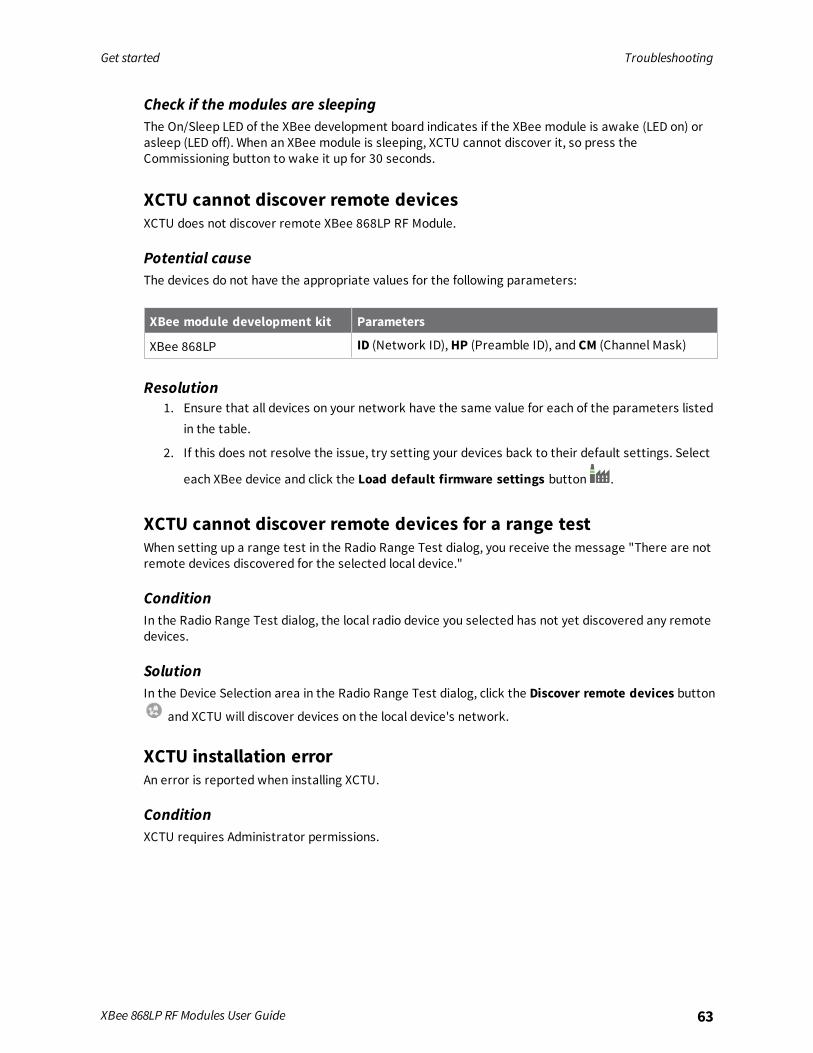
Check if the modules are sleepingThe On/Sleep LED of the XBee development board indicates if the XBee module is awake (LED on) orasleep (LED off). When an XBee module is sleeping, XCTU cannot discover it, so press theCommissioning button to wake it up for 30 seconds.
XCTU cannot discover remote devicesXCTU does not discover remote XBee 868LP RF Module.
Potential causeThe devices do not have the appropriate values for the following parameters:
XBee module development kit Parameters
XBee 868LP ID (Network ID),HP (Preamble ID), and CM (Channel Mask)
Resolution1. Ensure that all devices on your network have the same value for each of the parameters listed
in the table.
2. If this does not resolve the issue, try setting your devices back to their default settings. Select
each XBee device and click the Load default firmware settings button .
XCTU cannot discover remote devices for a range testWhen setting up a range test in the Radio Range Test dialog, you receive the message "There are notremote devices discovered for the selected local device."
ConditionIn the Radio Range Test dialog, the local radio device you selected has not yet discovered any remotedevices.
SolutionIn the Device Selection area in the Radio Range Test dialog, click the Discover remote devices button
and XCTU will discover devices on the local device's network.
XCTU installation errorAn error is reported when installing XCTU.
ConditionXCTU requires Administrator permissions.

Get started Troubleshooting
XBee 868LP RF Modules User Guide 64
SolutionCheck that you have Administrator access on the computer where you are installing XCTU. OnWindows systems, a User Account Control dialog may appear when you install XCTU or try to run theXCTU program. You must answer yes when prompted to allow the program to make changes to yourcomputer, or XCTU will not work correctly. Note that you may also need to talk to your networkmanager to gain permission to install or run applications as administrator.
Operation
Operation 66Listen Before Talk and Automatic Frequency Agility 66Single frequency mode bandmode 67Serial communications 67Configuration considerations 71Serial buffers 72UART flow control 72Force UART operation 73Serial interface protocols 73
XBee 868LP RF Modules User Guide 65

Operation Operation
XBee 868LP RF Modules User Guide 66
OperationThe XBee 868LP RF Module uses a multi-layered firmware base to order the flow of data, dependenton the hardware and software configuration you choose. The following configuration block diagramshows the host serial interface as the physical starting point and the antenna as the physical endpointfor the transferred data. A block must be able to touch another block above or below it for the twointerfaces to interact. For example, if the device uses SPI mode, Transparent mode is not available asshown in the following image:
The command handler code processes commands from AT Command Mode or API Mode; see ATcommands. The command handler also processes commands from remote devices; see Remote ATcommands.
Listen Before Talk and Automatic Frequency AgilityThis device implements Listen Before Talk (LBT) and Automatic Frequency Agility (AFA). The advantageof LBT with AFA is that the device bypasses the Duty Cycle requirement imposed by Europeanstandards. LBT+AFA requires that you use at least two frequencies for transmission.This feature provides a level of fairness to the devices in a given area. Before this device transmits, itsenses a channel to determine if there is activity by taking an RSSI measurement for 5 ms. If themeasurement is below the threshold, the device transmits on that channel. If there is activity, thatchannel is not used, and the device listens for at least 5 ms to allow transmissions to be received.After the device transmits on a channel, it will not transmit on that channel again until the minimumTX off time has been met, which is greater than 100 ms. It is useful to have many channels in yourchannel mask, so transmissions are less likely to be delayed.European requirements also state that only 100 seconds of transmission may occur over the period ofan hour on 200 kHz of spectrum. This method simplifies and optimizes the calculations of spectrumuse over the period of one hour. The standard states that the more channels you have, the moretransmission time you have in a one hour period. Calculate the effective duty cycle based on thenumber of available channels enabled as follows:
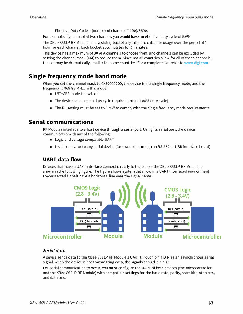
Operation Single frequency mode band mode
XBee 868LP RF Modules User Guide 67
Effective Duty Cycle = (number of channels * 100)/3600.For example, if you enabled two channels you would have an effective duty cycle of 5.6%.The XBee 868LP RF Module uses a sliding bucket algorithm to calculate usage over the period of 1hour for each channel. Each bucket accumulates for 6 minutes.This device has a maximum of 30 AFA channels to choose from, and channels can be excluded bysetting the channel mask (CM) to reduce them. Since not all countries allow for all of these channels,the set may be dramatically smaller for some countries. For a complete list, refer to www.digi.com.
Single frequency mode band modeWhen you set the channel mask to 0x20000000, the device is in a single frequency mode, and thefrequency is 869.85 MHz. In this mode:
n LBT+AFA mode is disabled.
n The device assumes no duty cycle requirement (or 100% duty cycle).
n The PL setting must be set to 5 mW to comply with the single frequency mode requirements.
Serial communicationsRF Modules interface to a host device through a serial port. Using its serial port, the devicecommunicates with any of the following:
n Logic and voltage compatible UART
n Level translator to any serial device (for example, through an RS-232 or USB interface board)
UART data flowDevices that have a UART interface connect directly to the pins of the XBee 868LP RF Module asshown in the following figure. The figure shows system data flow in a UART-interfaced environment.Low-asserted signals have a horizontal line over the signal name.
Serial dataA device sends data to the XBee 868LP RF Module's UART through pin 4 DIN as an asynchronous serialsignal. When the device is not transmitting data, the signals should idle high.For serial communication to occur, you must configure the UART of both devices (the microcontrollerand the XBee 868LP RF Module) with compatible settings for the baud rate, parity, start bits, stop bits,and data bits.
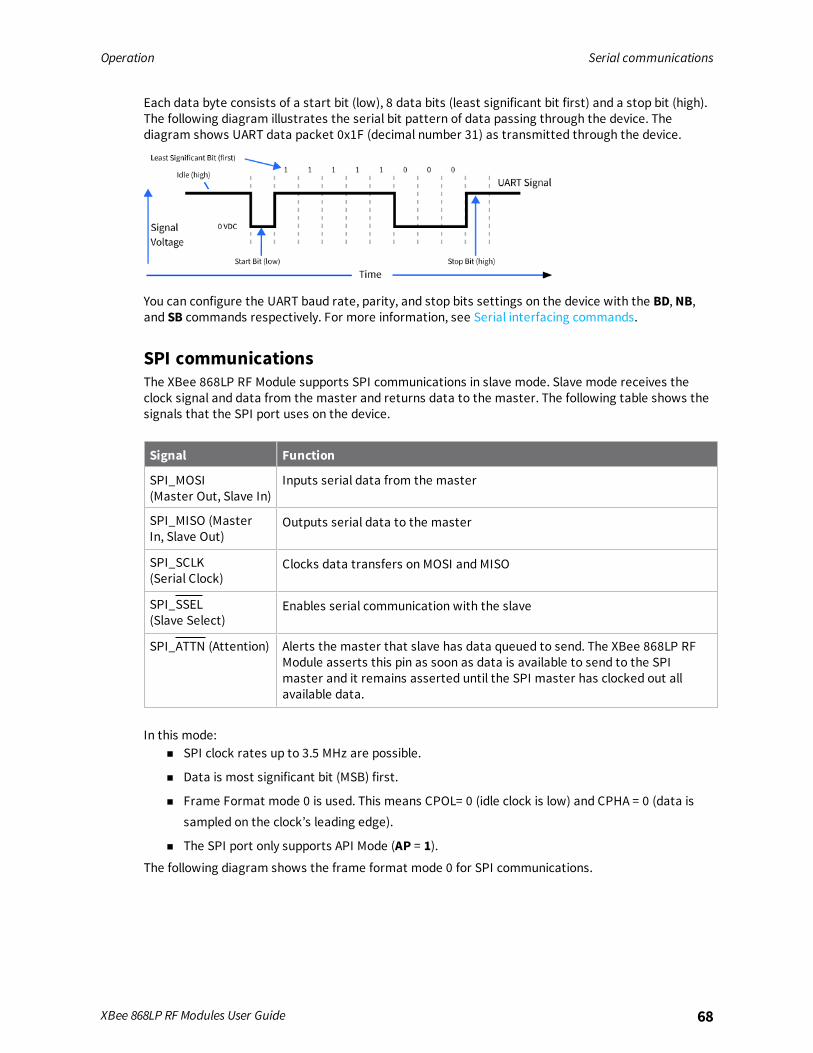
Operation Serial communications
XBee 868LP RF Modules User Guide 68
Each data byte consists of a start bit (low), 8 data bits (least significant bit first) and a stop bit (high).The following diagram illustrates the serial bit pattern of data passing through the device. Thediagram shows UART data packet 0x1F (decimal number 31) as transmitted through the device.
You can configure the UART baud rate, parity, and stop bits settings on the device with the BD, NB,and SB commands respectively. For more information, see Serial interfacing commands.
SPI communicationsThe XBee 868LP RF Module supports SPI communications in slave mode. Slave mode receives theclock signal and data from the master and returns data to the master. The following table shows thesignals that the SPI port uses on the device.
Signal Function
SPI_MOSI(Master Out, Slave In)
Inputs serial data from the master
SPI_MISO (MasterIn, Slave Out)
Outputs serial data to the master
SPI_SCLK (Serial Clock)
Clocks data transfers on MOSI and MISO
SPI_SSEL(Slave Select)
Enables serial communication with the slave
SPI_ATTN (Attention) Alerts the master that slave has data queued to send. The XBee 868LP RFModule asserts this pin as soon as data is available to send to the SPImaster and it remains asserted until the SPI master has clocked out allavailable data.
In this mode:n SPI clock rates up to 3.5 MHz are possible.
n Data is most significant bit (MSB) first.
n Frame Format mode 0 is used. This means CPOL= 0 (idle clock is low) and CPHA = 0 (data issampled on the clock’s leading edge).
n The SPI port only supports API Mode (AP = 1).The following diagram shows the frame format mode 0 for SPI communications.

Operation Serial communications
XBee 868LP RF Modules User Guide 69
SPI operationThis section specifies how SPI is implemented on the device, what the SPI signals are, and how fullduplex operations work.
SPI implementationThe XBee 868LP RF Module operates as a SPI slave only. This means an external master provides theclock and decides when to send data. The XBee 868LP RF Module supports an external clock rate of upto 3.5 Mb/s.The device transmits and receives data with the most significant bit first using SPI mode 0. Thismeans the CPOL and CPHA are both 0. We chose Mode 0 because it is the typical default for mostmicrocontrollers and simplifies configuring the master.
SPI signalsThe specification for SPI includes the four signals: SPI_MISO, SPI_MOSI, SPI_CLK, and SPI_SSEL. Usingonly these four signals, the master cannot know when the slave needs to send and the SPI slavecannot transmit unless enabled by the master. For this reason, the SPI_ATTN signal is available. Thisallows the device to alert the SPI master that it has data to send. In turn, the SPI master asserts SPI_SSEL and starts SPI_CLK unless these signals are already asserted and active respectively. This allowsthe XBee 868LP RF Module to send data to the master.The following table names the SPI signals and specifies their pinouts. It also describes the operationof each pin.
Signal namePinnumber
ApplicableATcommand Description
SPI_MISO(Master In, Slave out)
17 P5 When SPI_SSEL is asserted (low) and SPI_CLK isactive, the device outputs the data on this line atthe SPI_CLK rate. When SPI_SSEL is de-asserted(high), this output should be tri-stated such thatanother slave device can drive the line.

Operation Serial communications
XBee 868LP RF Modules User Guide 70
Signal namePinnumber
ApplicableATcommand Description
SPI_MOSI(Master out, Slave in)
16 P6 The SPI master outputs data on this line at theSPI_CLK rate after it selects the desired slave.When you configure the device for SPI operations,this pin is an input.
SPI_SSEL(Slave Select)(Master out, Slave in)
15 P7 The SPI master outputs a low signal on this line toselect the desired slave. When you configure forSPI operations, this pin is an input.
SPI_CLK(Clock)(Master out, Slave in)
14 P8 The SPI master outputs a clock on this pin, andthe rate must not exceed the maximum allowed,3.5 Mb/s. When you configure the device for SPIoperations, this pin is an input.
SPI_ATTN(Attention)(Master in, Slave out)
12 P9 The device asserts this pin low when it has datato send to the SPI master. When you configure forSPI operations, it is an output (not tri-stated).
Note By default, the inputs have pull-up resistors enabled. See PR (Pull-up/Down Resistor Enable) todisable the pull-up resistors. When the SPI pins are not connected but the pins are configured for SPIoperation, the pull-ups are required for proper UART operation.
Full duplex operationSPI on the XBee 868LP RF Module requires that you use API mode (without escaping) to packetizedata. By design, SPI is a full duplex protocol even when data is only available in one direction. Thismeans that when a device receives data, it also transmits and that data is normally invalid. Likewise,when the device transmits data, invalid data is probably received. To determine whether or notreceived data is invalid, we packetize the data with API packets.SPI allows for valid data from the slave to begin before, at the same time, or after valid data beginsfrom the master. When the master is sending data to the slave and the slave has valid data to send inthe middle of receiving data from the master, this allows a true full duplex operation where data isvalid in both directions for a period of time. Not only must the master and the slave both be able tokeep up with the full duplex operation, but both sides must honor the protocol as specified.The following diagram illustrates the SPI interface while valid data is being sent in both directions.

Operation Configuration considerations
XBee 868LP RF Modules User Guide 71
Low power operationSleepmodes generally work the same on SPI as they do on UART. By default, Digi configures DIO8(SLEEP_REQUEST) as a peripheral and during pin sleep it wakes the device and puts it to sleep. Thisapplies to both the UART and SPI serial interfaces.If SLEEP_REQUEST is not configured as a peripheral and SPI_SSEL is configured as a peripheral, thenpin sleep is controlled by SPI_SSEL rather than by SLEEP_REQUEST. Asserting SPI_SSEL by driving itlow either wakes the device or keeps it awake. Negating SPI_SSEL by driving it high puts the device tosleep.Using SPI_SSEL to control sleep and to indicate that the SPI master has selected a particular slavedevice has the advantage of requiring one less physical pin connection to implement pin sleep on SPI.It has the disadvantage of putting the device to sleep whenever the SPI master negates SPI_SSEL(meaning time is lost waiting for the device to wake), even if that was not the intent.If the user has full control of SPI_SSEL so that it can control pin sleep, whether or not data needs to betransmitted, then sharing the pin may be a good option in order to make the SLEEP_REQUEST pinavailable for another purpose.If the device is one of multiple slaves on the SPI, then the device sleeps while the SPI master talks tothe other slave, but this is acceptable in most cases.If you do not configure either pin as a peripheral, then the device stays awake, being unable to sleep inSM1 mode.
Configuration considerationsThe configuration considerations are:
n How do you select the serial port? For example, should you use the UART or the SPI port?
n If you use the SPI port, what data format should you use in order to avoid processing invalidcharacters while transmitting?
n What SPI options do you need to configure?
Serial port selectionIn the default configuration both the UART and SPI ports are configured for serial port operation. Inthis case, serial data goes out the UART until the host device asserts the SPI_SSEL signal. Thereafterall serial communications operate only on the SPI interface until a reset occurs.If you enable only the UART, the XBee 868LP RF Module uses only the UART, and ignores the SPI_SSEL.If you enable only the SPI, the XBee 868LP RF Module uses only the SPI, and ignores UARTcommunications.If neither serial port is enabled, the device will not support serial operations and all communicationsmust occur over the air. The device discards all data that would normally go to the serial port.
Data formatThe SPI only operates in API mode 1. The device does not support Transparent mode or API mode 2(which escapes control characters). This means that the AP configuration only applies to the UART,and the device ignores it while using SPI.
Operation Serial buffers
XBee 868LP RF Modules User Guide 72
SPI parametersMost host processors with SPI hardware allow you to set the bit order, clock phase and polarity. Forcommunication with all XBee 868LP RF Modules, the host processor must set these options as follows:
n Bit order: send MSB first
n Clock phase (CPHA): sample data on first (leading) edge
n Clock polarity (CPOL): first (leading) edge rises
All XBee 868LP RF Modules use SPI mode 0 and MSB first. Mode 0 means that data is sampled on theleading edge and that the leading edge rises. MSB first means that bit 7 is the first bit of a byte sentover the interface.
Serial buffersTo enable the UART port, DIN and DOUT must be configured as peripherals. To enable the SPI port,SPI_MISO, SPI_MOSI, SPI_SSEL, and SPI_CLK must be enabled as peripherals. If both ports areenabled, output goes to the UART until the first input on SPI. This is the default configuration.When input occurs on either port, that port is selected as the active port and no input or output isallowed on the other port until the next reset of the module.If you change the configuration to configure only one port, that port is the only one enabled or used. Ifthe parameters are written with only one port enabled, the port that is not enabled is not used eventemporarily after the next reset.If both ports are disabled on reset, the device uses the UART regardless of the incorrect configurationto ensure that at least one serial port is operational.
Serial receive bufferWhen serial data enters the device through the DIN pin (or the MOSI pin), it stores the data in theserial receive buffer until the device can process it. Under certain conditions, the device may not beable to process data in the serial receive buffer immediately. If large amounts of serial data are sentto the device such that the serial receive buffer would overflow, then it discards new data. If the UARTis in use, you can avoid this by the host side honoring CTS flow control.If the SPI is the serial port, no hardware flow control is available. It is your responsibility to ensurethat the receive buffer does not overflow. One reliable strategy is to wait for a TX_STATUS responseafter each frame sent to ensure that the device has had time to process it.
Serial transmit bufferWhen the device receives RF data, it moves the data into the serial transmit buffer and sends it outthe UART or SPI port. If the serial transmit buffer becomes full and the system buffers are also full,then it drops the entire RF data packet. Whenever the device receives data faster than it can processand transmit the data out the serial port, there is a potential of dropping data.
UART flow controlYou can use the RTS and CTS pins to provide RTS and/or CTS flow control. CTS flow control provides anindication to the host to stop sending serial data to the device. RTS flow control allows the host tosignal the device to not send data in the serial transmit buffer out the UART. To enable RTS/CTS flowcontrol, use the D6 and D7 commands.
Note Serial port flow control is not possible when using the SPI port.

Operation Force UART operation
XBee 868LP RF Modules User Guide 73
CTS flow controlIf you enable CTS flow control (D7 command), when the serial receive buffer is 17 bytes away frombeing full, the device de-asserts CTS (sets it high) to signal to the host device to stop sending serialdata. The device reasserts CTS after the serial receive buffer has 34 bytes of space. See FT (FlowControl Threshold) for the buffer size.
RTS flow controlIf you send the D6 command to enable RTS flow control, the device does not send data in the serialtransmit buffer out the DOUT pin as long as RTS is de-asserted (set high). Do not de-assert RTS forlong periods of time or the serial transmit buffer will fill. If the device receives an RF data packet andthe serial transmit buffer does not have enough space for all of the data bytes, it discards the entireRF data packet.The UART Data Present Indicator is a useful feature when using RTS flow control. When enabled, theDIO19 line asserts (low asserted) when UART data is queued to be transmitted from the device. Formore information, see P9 (SPI_ATTN).If the device sends data out the UART when RTS is de-asserted (set high) the device could send up tofive characters out the UART port after RTS is de-asserted.
Force UART operation
ConditionYou configure a device with only the SPI enabled and no SPI master is available to access the SPI slaveport
SolutionUse the following steps to recover the device to UART operation:
1. Hold the DIN/CONFIG low at reset time.
2. DIN/CONFIG forces a default configuration on the UART at 9600 baud and brings up the devicein Command Mode on the UART port.
You can send the appropriate commands to the device to configure it for UART operation.3. If you write these parameters to the device, the module comes up with the UART enabled on
the next reset.
Serial interface protocolsThe XBee 868LP RF Module supports both Transparent and Application Programming Interface (API)serial interfaces.
Transparent operating modeWhen operating in Transparent mode, the devices act as a serial line replacement. The device queuesup all UART data received through the DIN pin for RF transmission. When RF data is received, thedevice sends the data out through the serial port. Use the Commandmode interface to configure thedevice configuration parameters.
Operation Serial interface protocols
XBee 868LP RF Modules User Guide 74
Note Transparent operation is not available when using SPI.
The device buffers data in the serial receive buffer and packetizes and transmits the data when itreceives the following:
n No serial characters for the amount of time determined by the RO (Packetization Timeout)parameter. If RO = 0, packetization begins when the device received a character.
n Command Mode Sequence (GT + CC + GT). Any character buffered in the serial receive bufferbefore the device transmits the sequence.
n Maximum number of characters that fit in an RF packet.
API operating modeAPI operating mode is an alternative to Transparent operating mode. The frame-based API extendsthe level to which a host application can interact with the networking capabilities of the device. Whenin API mode, the device contains all data entering and leaving in frames that define operations orevents within the device.The API provides alternative means of configuring devices and routing data at the host applicationlayer. A host application can send data frames to the device that contain address and payloadinformation instead of using Commandmode to modify addresses. The device sends data frames tothe application containing status packets, as well as source and payload information from receiveddata packets.The API operation option facilitates many operations such as:
n Transmitting data to multiple destinations without entering Command Mode
n Receive success/failure status of each transmitted RF packet
n Identify the source address of each received packet
Comparing Transparent and API modesThe following table compares the advantages of transparent and API modes of operation:
Feature Description
Transparent mode features
Simple interface All received serial data is transmitted unless the device is in Commandmode
Easy to support It is easier for an application to support Transparent operation andCommandmode
API mode features
Easy to manage datatransmissions tomultiple destinations
Transmitting RF data to multiple remote devices only requires theapplication to change the address in the API frame. This process is muchfaster than in Transparent mode where the application must enterCommandmode, change the address, exit Commandmode, and thentransmit data.
Operation Serial interface protocols
XBee 868LP RF Modules User Guide 75
Feature Description
Each API transmissioncan return a transmitstatus frame indicatingthe success or reasonfor failure
Because acknowledgments are sent out of the serial interface, thisprovides more information about the health of the RF network and canbe used to debug issues after the network has been deployed.
Received data framesindicate the sender'saddress
All received RF data API frames indicate the source address
Advanced addressingsupport
API transmit and receive frames can expose addressing fields includingsource and destination endpoints, cluster ID, and profile ID
Advanced networkingdiagnostics
API frames can provide indication of I/O samples from remote devices,and node identification messages.
Remote Configuration Set/read configuration commands can be sent to remote devices toconfigure them as needed using the API
We recommend API mode when a device:n Sends RF data to multiple destinations
n Sends remote configuration commands to manage devices in the network
n Receives RF data packets from multiple devices, and the application needs to know whichdevice sent which packet
n Must support multiple endpoints, cluster IDs, and/or profile IDs
n Uses the Device Profile services
API mode is required when:n Receiving I/O samples from remote devices
n Using SPI for the serial port
If the conditions listed above do not apply (for example, a sensor node, router, or a simple application),then Transparent operation might be suitable. It is acceptable to use a mixture of devices running APImode and Transparent mode in a network.
Modes
The XBee 868LP RF Module is in Receive Mode when it is not transmitting data. The device shifts intothe other modes of operation under the following conditions:
n Transmit Mode (Serial data in the serial receive buffer is ready to be packetized)
n Sleep Mode
n Command Mode (Command Mode Sequence is issued (not available when using the SPI port)
Transmit mode 77Receive mode 77Commandmode 77Sleepmode 79
XBee 868LP RF Modules User Guide 76
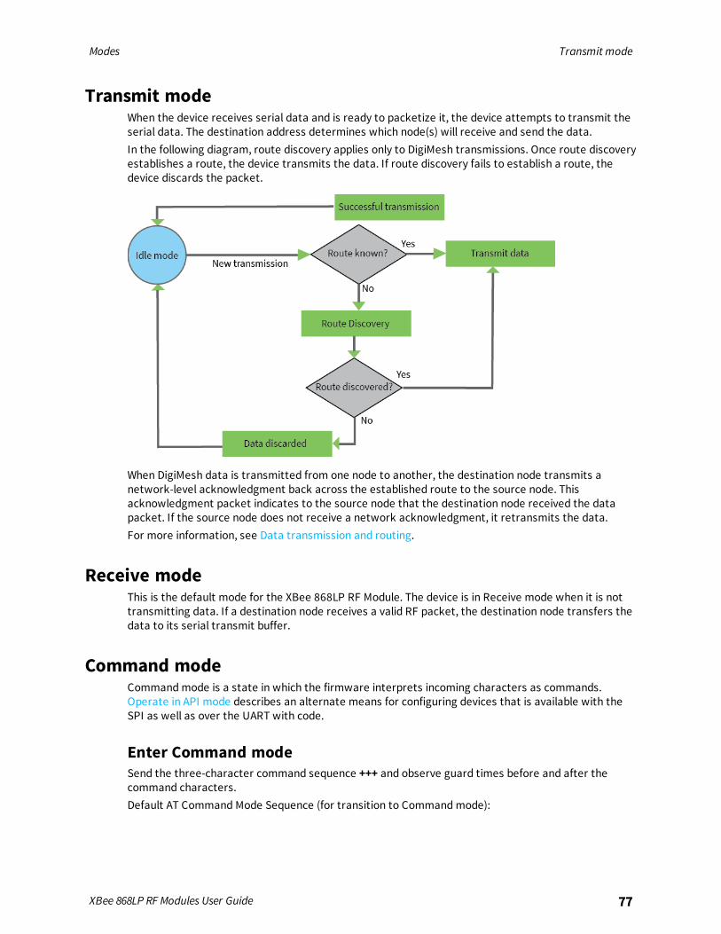
Modes Transmit mode
XBee 868LP RF Modules User Guide 77
Transmit modeWhen the device receives serial data and is ready to packetize it, the device attempts to transmit theserial data. The destination address determines which node(s) will receive and send the data.In the following diagram, route discovery applies only to DigiMesh transmissions. Once route discoveryestablishes a route, the device transmits the data. If route discovery fails to establish a route, thedevice discards the packet.
When DigiMesh data is transmitted from one node to another, the destination node transmits anetwork-level acknowledgment back across the established route to the source node. Thisacknowledgment packet indicates to the source node that the destination node received the datapacket. If the source node does not receive a network acknowledgment, it retransmits the data.For more information, see Data transmission and routing.
Receive modeThis is the default mode for the XBee 868LP RF Module. The device is in Receive mode when it is nottransmitting data. If a destination node receives a valid RF packet, the destination node transfers thedata to its serial transmit buffer.
Command modeCommandmode is a state in which the firmware interprets incoming characters as commands.Operate in API mode describes an alternate means for configuring devices that is available with theSPI as well as over the UART with code.
Enter Command modeSend the three-character command sequence +++ and observe guard times before and after thecommand characters.Default AT Command Mode Sequence (for transition to Commandmode):
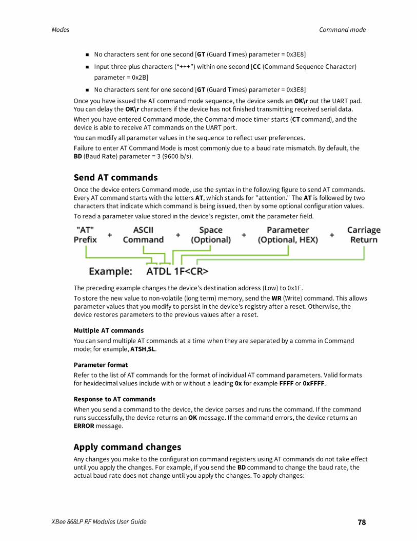
Modes Command mode
XBee 868LP RF Modules User Guide 78
n No characters sent for one second [GT (Guard Times) parameter = 0x3E8]
n Input three plus characters (“+++”) within one second [CC (Command Sequence Character)parameter = 0x2B]
n No characters sent for one second [GT (Guard Times) parameter = 0x3E8]
Once you have issued the AT commandmode sequence, the device sends anOK\r out the UART pad.You can delay the OK\r characters if the device has not finished transmitting received serial data.When you have entered Commandmode, the Commandmode timer starts (CT command), and thedevice is able to receive AT commands on the UART port.You can modify all parameter values in the sequence to reflect user preferences.Failure to enter AT Command Mode is most commonly due to a baud rate mismatch. By default, theBD (Baud Rate) parameter = 3 (9600 b/s).
Send AT commandsOnce the device enters Commandmode, use the syntax in the following figure to send AT commands.Every AT command starts with the letters AT, which stands for "attention." The AT is followed by twocharacters that indicate which command is being issued, then by some optional configuration values.To read a parameter value stored in the device’s register, omit the parameter field.
The preceding example changes the device's destination address (Low) to 0x1F.To store the new value to non-volatile (long term) memory, send the WR (Write) command. This allowsparameter values that you modify to persist in the device's registry after a reset. Otherwise, thedevice restores parameters to the previous values after a reset.
Multiple AT commandsYou can sendmultiple AT commands at a time when they are separated by a comma in Commandmode; for example, ATSH,SL.
Parameter formatRefer to the list of AT commands for the format of individual AT command parameters. Valid formatsfor hexidecimal values include with or without a leading 0x for example FFFF or 0xFFFF.
Response to AT commandsWhen you send a command to the device, the device parses and runs the command. If the commandruns successfully, the device returns anOKmessage. If the command errors, the device returns anERRORmessage.
Apply command changesAny changes you make to the configuration command registers using AT commands do not take effectuntil you apply the changes. For example, if you send the BD command to change the baud rate, theactual baud rate does not change until you apply the changes. To apply changes:
Modes Sleep mode
XBee 868LP RF Modules User Guide 79
1. Send the AC (Apply Changes) command.or:
2. Exit Commandmode.
Exit Command mode1. Send the CN (Exit Command Mode) command followed by a carriage return.
or:
2. If the device does not receive any valid AT commands within the time specified by CT(Command Mode Timeout), it returns to Idle Mode.
For an example of programming the device using AT Commands and descriptions of each configurableparameter, see AT commands.
Sleep modeSleepmodes allow the device to enter states of low power consumption when not in use. The XBee868LP RF Module supports both pin sleep (Sleepmode entered on pin transition) and cyclic sleep(device sleeps for a fixed time).Sleepmodes allow the device to enter states of low power consumption when not in use. XBeedevices support both pin sleep, where the device enters sleepmode upon pin transition, and cyclicsleep, where the device sleeps for a fixed time. For more information, see Sleepmodes.

Sleep modes
About sleepmodes 81Normal mode 81Asynchronous pin sleepmode 82Asynchronous cyclic sleepmode 82Asynchronous cyclic sleep with pin wake upmode 82Synchronous sleep support mode 82Synchronous cyclic sleepmode 82Wake timer 83Indirect messaging and polling 83Sleeping routers 84Sleep coordinator sleepmodes in the DigiMesh network 84
XBee 868LP RF Modules User Guide 80
Sleep modes About sleep modes
XBee 868LP RF Modules User Guide 81
About sleep modesA number of low-power modes exist to enable devices to operate for extended periods of time onbattery power. Use the SM command to enable these sleepmodes. The sleepmodes arecharacterized as either:
n Asynchronous (SM = 1, 4, 5).
n Synchronous (SM = 7, 8).
Asynchronous modesn Do not use asynchronous sleepmodes in a synchronous sleeping network, and vice versa.
n Use the asynchronous sleepmodes to control the sleep state on a device by device basis.
n Do not use devices operating in asynchronous sleepmode to route data.
n We strongly encourage you to set asynchronous sleeping devices as end-devices using the CEcommand. This prevents the node from attempting to route data.
Synchronous modesSynchronous sleepmakes it possible for all nodes in the network to synchronize their sleep and waketimes. All synchronized cyclic sleep nodes enter and exit a low power state at the same time.This forms a cyclic sleeping network.
n A device acting as a sleep coordinator sends a special RF packet called a sync message tosynchronize nodes.
n To make a device in the network a coordinator, a node uses several resolution criteria througha process called nomination.
n The sleep coordinator sends one sync message at the beginning of each wake period. Thecoordinator sends the sync message as a broadcast and every node in the network repeats it.
n You can change the sleep and wake times for the entire network by locally changing thesettings on an individual device. The network uses the most recently set sleep settings.
Normal modeSet SM to 0 to enter Normal mode.Normal mode is the default sleepmode. If a device is in this mode, it does not sleep and is alwaysawake.Use mains-power for devices in Normal mode.A device in Normal mode synchronizes to a sleeping network, but does not observe synchronizationdata routing rules; it routes data at any time, regardless of the network's wake state.When synchronized, a device in Normal mode relays sync messages that sleep-compatible nodesgenerate, but does not generate sync messages itself.Once a device in Normal mode synchronizes with a sleeping network, you can put it into a sleep-compatible sleepmode at any time.

Sleep modes Asynchronous pin sleep mode
XBee 868LP RF Modules User Guide 82
Asynchronous pin sleep modeSet SM to 1 to enter asynchronous pin sleepmode.Pin sleep allows the device to sleep and wake according to the state of the SLEEP_RQ pin (pin 9).When you assert SLEEP_RQ (high), the device finishes any transmit or receive operations and enters alow-power state.When you de-assert SLEEP_RQ (low), the device wakes from pin sleep.
Asynchronous cyclic sleep modeSet SM to 4 to enter asynchronous cyclic sleepmode.Cyclic sleep allows the device to sleep for a specific time and wake for a short time to poll.If the device receives serial or RF data while awake, it extends the time before it returns to sleep bythe specific amount the ST command provides. Otherwise, it enters sleepmode immediately.The ON_SLEEP line asserts (high) when the device wakes, and is de-asserted (low) when the devicesleeps.If you use the D7 command to enable hardware flow control, the CTS pin asserts (low) when thedevice wakes and can receive serial data, and de-asserts (high) when the device sleeps.
Asynchronous cyclic sleep with pin wake up modeSet SM to 5 to enter Asynchronous cyclic sleep with pin wake upmode.This mode is a slight variation on (SM = 4) that allows the device to wake prematurely by asserting theSLEEP_RQ pin (pin 9). In (SM =5 ), the device wakes after the sleep period expires, or if a high-to-lowtransition occurs on the SLEEP_RQ pin.
Synchronous sleep support modeSet SM to 7 to enter synchronous sleep support mode.A device in synchronous sleep support mode synchronizes itself with a sleeping network but will notitself sleep. At any time, the device responds to new devices that are attempting to join the sleepingnetwork with a sync message. A sleep support device only transmits normal data when the otherdevices in the sleeping network are awake. You can use sleep support devices as preferred sleepcoordinator devices and as aids in adding new devices to a sleeping network.
Synchronous cyclic sleep modeSet SM to 8 to enter synchronous cyclic sleepmode.A device in synchronous cyclic sleepmode sleeps for a programmed time, wakes in unison with othernodes, exchanges data and sync messages, and then returns to sleep. While asleep, it cannot receiveRF messages or receive data (including commands) from the UART port.Generally, the network’s sleep coordinator specifies the sleep and wake times based on its SP and STsettings. The device only uses these parameters at startup until the device synchronizes with thenetwork.When a device has synchronized with the network, you can query its sleep and wake times with theOS andOW commands respectively.If D9 = 1 (ON_SLEEP enabled) on a cyclic sleep node, the ON_SLEEP line asserts when the device isawake and de-asserts when the device is asleep.
Sleep modes Wake timer
XBee 868LP RF Modules User Guide 83
If D7 = 1, the device de-asserts CTS while asleep.A newly-powered, unsynchronized, sleeping device polls for a synchronizedmessage and then sleepsfor the period that the SP command specifies, repeating this cycle until it synchronizes by receiving async message. Once it receives a sync message, the device synchronizes itself with the network.
Note Configure all nodes in a synchronous sleep network to operate in either synchronous sleepsupport mode or synchronous cyclic sleepmode. asynchronous sleeping nodes are not compatiblewith synchronous sleeping nodes.
Wake timerIn asynchronous cyclic sleepmode (SM = 4 or SM = 5), if a device receives serial or RF data, it starts asleep timer (time until sleep). Any data received serially or by RF link resets the timer. Use ST (WakeTime) to set the timer duration. While the device is awake, it sends regular poll requests to its parentto check for buffered data. If the RF data rate is 80 kb/s (BR = 1), the poll occurs every 100 ms.Otherwise, (BR = 0), the poll occurs every 300 ms. The device returns to sleep when the sleep timerexpires.
Indirect messaging and pollingTo enable reliable communication with sleeping devices, you can use the CE (Routing/MessagingMode) command to enable indirect messaging and polling.
Indirect messagingIndirect messaging is a communication mode designed for communicating with asynchronoussleeping devices. A device can enable indirect messaging by making itself an indirect messagingcoordinator with the CE command. An indirect messaging coordinator does not immediately transmita P2MP unicast when it is received over the serial port. Instead the device holds onto the data until itis requested via a poll. On receiving a poll, the indirect messaging coordinator sends a queued datapacket (if available) to the requestor.Because it is possible for a polling device to be eliminated, a mechanism is in place to purgeunrequested data packets. If the coordinator holds an indirect data packet for an indirect messagingpoller for more than 2.5 times its SP value, then the packet is purged. We suggest setting the SP ofthe coordinator to the same value as the highest SP time that exists among the pollers in thenetwork. If the coordinator is in API mode, a TxStatus message is generated for a purged data packetwith a status of 0x75 (INDIRECT_MESSAGE_UNREQUESTED).An indirect messaging coordinator queues up as many data packets as it has buffers available. Afterthe coordinator uses all of its available buffers, it holds transmission requests unprocessed on theserial input queue. After the serial input queue is full, the device de-asserts CTS (if hardware flowcontrol is enabled). After receiving a poll or purging data from the indirect messaging queue thebuffers become available again.Indirect messaging has no effect on broadcasts. These messages are sent immediately when receivedover the serial port and are not put on the indirect messaging queue.
PollingPolling is the automatic process by which a node can request data from an indirect messagingcoordinator. To enable polling on a device, configure it as an end device with the CE command. Whenyou enable polling, the device sends a poll request a minimum of once every 100 ms. When the device
Sleep modes Sleeping routers
XBee 868LP RF Modules User Guide 84
sends normal data to the destination specified by the DH/DL of end device module, the data alsofunctions as a poll.When a polling device is also an asynchronous sleeping device, that device sends a poll shortly afterwaking from sleep. After that first poll is sent, the device sends polls in the normal manner describedpreviously until it returns to sleep.
Sleeping routersThe Sleeping Router feature of DigiMesh makes it possible for all nodes in the network to synchronizetheir sleep and wake times. All synchronized cyclic sleep nodes enter and exit a low power state at thesame time. This forms a cyclic sleeping network.Devices synchronize by receiving a special RF packet called a sync message sent by a device acting asa sleep coordinator. A device in the network becomes a sleep coordinator through a process callednomination. The sleep coordinator sends one sync message at the beginning of each wake period. Thedevice sends a sync message as a broadcast that is repeated by every device in the network. Tochange the sleep and wake times for the entire network, change the settings on an individual nodelocally. The network uses the most recently set sleep settings.For more information, see Become a sleep coordinator.
Sleep coordinator sleep modes in the DigiMesh networkIn a synchronized sleeping network, one node acts as the sleep coordinator. During normaloperations, at the beginning of a wake cycle the sleep coordinator sends a sync message as abroadcast to all nodes in the network. This message contains synchronization information and thewake and sleep times for the current cycle. All cyclic sleep nodes that receive a sync message remainawake for the wake time and then sleep for the specified sleep period.The sleep coordinator sends one sync message at the beginning of each cycle with the current wakeand sleep times. All router nodes that receive this sync message relay the message to the rest of thenetwork. If the sleep coordinator does not hear a rebroadcast of the sync message by one of itsimmediate neighbors, then it re-sends the message one additional time.If you change the SP or ST parameters, the network does not apply the new settings until thebeginning of the next wake time. For more information, see Change sleep parameters.A sleeping router network is robust enough that an individual node can go several cycles withoutreceiving a sync message, due to RF interference, for example. As a node misses sync messages, thetime available for transmitting messages during the wake time reduces to maintain synchronizationaccuracy. By default, a device reduces its active sleep time progressively as it misses sync messages.
Synchronization messagesA sleep coordinator regularly sends sync messages to keep the network in sync. Unsynchronizednodes also sendmessages requesting sync information.Sleep compatible nodes use Deployment mode when they first power up and the sync message hasnot been relayed. A sleep coordinator in Deployment mode rapidly sends sync messages until itreceives a relay of one of those messages. Deployment mode:
n Allows you to effectively deploy a network.
n Allows a sleep coordinator that resets to rapidly re-synchronize with the rest of the network.
If a node exits deployment mode and then receives a sync message from a sleep coordinator that is inDeployment mode, it rejects the sync message and sends a corrective sync to the sleep coordinator.Use the SO (sleep options) command to disable deployment mode. This option is enabled by default.

Sleep modes Sleep coordinator sleep modes in the DigiMesh network
XBee 868LP RF Modules User Guide 85
A sleep coordinator that is not in deployment mode sends a sync message at the beginning of thewake cycle. The sleep coordinator listens for a neighboring node to relay the sync. If it does not hearthe relay, the sleep coordinator sends the sync one additional time.A node that is not a sleep coordinator and has never been synchronized sends a message requestingsync information at the beginning of its wake cycle. Synchronized nodes which receive one of thesemessages respond with a synchronization packet.If you use the SO command to configure nodes as non-coordinators, and if the non-coordinators go sixor more sleep cycles without hearing a sync, they send a message requesting sync at the beginning oftheir wake period.The following diagram illustrates the synchronization behavior of sleep compatible devices.

Sleep modes Sleep coordinator sleep modes in the DigiMesh network
XBee 868LP RF Modules User Guide 86
Sleep modes Sleep coordinator sleep modes in the DigiMesh network
XBee 868LP RF Modules User Guide 87
Become a sleep coordinatorIn DigiMesh networks, a device can become a sleep coordinator in one of four ways:
n Define a preferred sleep coordinator
n A potential sleep coordinator misses three or more sync messages
n Press the Commissioning Pushbutton twice on a potential sleep coordinator
n Change the sleep timing values on a potential sleep coordinator
Preferred sleep coordinator optionYou can specify that a node always act as a sleep coordinator. To do this, set the preferred sleepcoordinator bit (bit 0) in the SO command to 1.A node with the sleep coordinator bit set always sends a sync message at the beginning of a wakecycle. To avoid network congestion and synchronization conflicts, do not set this bit on more than onenode in the network.Although it is not necessary to specify a preferred sleep coordinator, doing so improves networkperformance.A node that is centrally located in the network can serve as a good sleep coordinator, because itminimizes the number of hops a sync message takes to get across the network.A sleep support node and/or a node that is mains powered is a good candidate to be a sleepcoordinator.
CAUTION! Use the preferred sleep coordinator bit with caution. The advantages of usingthe option become weaknesses if you use it on a node that is not in the proper positionor configuration.
You can also use the preferred sleep coordinator option when you set up a network for the first time.When you start a network, you can configure a node as a sleep coordinator so it will begin sendingsleepmessages. After you set up the network, disable the preferred sleep coordinator bit.
Resolution criteria and selection optionThere is an optional selection process with resolution criteria that occurs on a node if it loses contactwith the network sleep coordinator. By default, this process is disabled. Use the SO command toenable this process. This process occurs automatically if a node loses contact with the previous sleepcoordinator.If you enable the process on any sleep compatible node, it is eligible to become the sleep coordinatorfor the network.A sleep compatible node may become a sleep coordinator if it:
n Misses three or more sync messages.
n Is not configured as a non-coordinator (presumably because the sleep coordinator has beendisabled).
Depending on the platform and other configurable options, such a node eventually uses the selectionprocess after a number of sleep cycles without a sync.A node that uses the selection process begins acting as the new network sleep coordinator.It is possible for multiple nodes to declare themselves as the sleep coordinator. If this occurs, thefirmware uses the following resolution criteria to identify the sleep coordinator from among the nodesusing the selection process:

Sleep modes Sleep coordinator sleep modes in the DigiMesh network
XBee 868LP RF Modules User Guide 88
1. Newer sleep parameters: the network considers a node using newer sleep parameters (SP andST) as higher priority to a node using older sleep parameters. See Change sleep parameters.
2. Preferred sleep coordinator: a node acting as a preferred sleep coordinator is higher priority toother nodes.
3. Sleep support node: sleep support nodes are higher priority to cyclic sleep nodes. You canmodify this behavior using the SO parameter.
4. Serial number: If the previous factors do not resolve the priority, the network considers thenode with the higher serial number to be higher priority.
Commissioning Pushbutton optionUse the Commissioning Pushbutton to select a device to act as the sleep coordinator.If you enable the Commissioning Pushbutton functionality, you can immediately select a device as asleep coordinator by pressing the Commissioning Pushbutton twice or by issuing the CB2 command.The device you select in this manner is still subject to the resolution criteria process.Only sleep coordinator nodes honor Commissioning Pushbutton nomination requests. A nodeconfigured as a non-sleep coordinator ignores commissioning button nomination requests.
Change sleep parametersAny sleep compatible node in the network that does not have the non-coordinator sleep option setcan make changes to the network’s sleep and wake times. If you change a node’s SP or ST to valuesdifferent from those that the network is using, the node becomes the sleep coordinator. The nodebegins sending sync messages with the new sleep parameters at the beginning of the next wakecycle.
n For normal operations, a device uses the sleep and wake parameters it gets from the sleepsync message, not the ones specified in its SP and ST parameters. It does not update the SPand ST parameters with the values of the sync message. Use the OS andOW commands toquery the operating network sleep and wake times currently being used by the node.
n Changing network parameters can cause a node to become a sleep coordinator and changethe sleep settings of the network. The following commands can cause this to occur: NH, NN,NQ, andMR.
For most applications, we recommend configuring the NH, NN, NQ, andMR network parametersduring initial deployment only.
Sleep guard timesTo compensate for variations in the timekeeping hardware of the various devices in a sleeping routernetwork, the network allocates sleep guard times at the beginning and end of the wake period. Thesize of the sleep guard time varies based on the sleep and wake times you select and the number ofsleep cycles that elapse since receiving the last sync message. The sleep guard time guarantees thata destination module will be awake when the source device sends a transmission. As a node missesmore andmore consecutive sync messages, the sleep guard time increases in duration and decreasesthe available transmission time.

Sleep modes Sleep coordinator sleep modes in the DigiMesh network
XBee 868LP RF Modules User Guide 89
Auto-early wake-up sleep optionSimilar to the sleep guard time, the auto early wake-up option decreases the sleep period based onthe number of sync messages a node misses. This option comes at the expense of battery life.Use the SO command to disable auto-early wake-up sleep. This option is enabled by default.
Select sleep parametersChoosing proper sleep parameters is vital to creating a robust sleep-enabled network with a desirablebattery life. To select sleep parameters that will be good for most applications, follow these steps:
1. Choose NH.
Based on the placement of the nodes in your network, select the appropriate values forthe NH (Network Hops) parameter .
We optimize the default values of NH to work for the majority of deployments. In mostcases, we suggest that you do not modify these parameters from their default values.Decreasing these parameters for small networks can improve battery life, but take careto not make the values too small.
2. Calculate the Sync Message Propagation Time (SMPT).
This is the maximum amount of time it takes for a sleep synchronization message topropagate to every node in the network. You can estimate this number with thefollowing formula:SMPT = NH*(MT+1)*18 ms.
3. Select the duty cycle you want.The ratio of sleep time to wake time is the factor that has the greatest effect on the device’spower consumption. Battery life can be estimated based on the following factors:
n sleep period
n wake time
n sleep current
n RX current
n TX current
n battery capacity
4. Choose the sleep period and wake time.
The wake time must be long enough to transmit the desired data as well as the sync message.The ST parameter automatically adjusts upwards to its minimum value when you change otherAT commands that affect it (SP, andNH).Use a value larger than this minimum. If a device misses successive sync messages, it reducesits available transmit time to compensate for possible clock drift. Budget a large enough STtime to allow for the device to miss a few sync messages and still have time for normal datatransmissions.
Start a sleeping synchronous networkBy default, all new nodes operate in normal (non-sleep) mode. To start a synchronous sleepingnetwork, follow these steps:
Sleep modes Sleep coordinator sleep modes in the DigiMesh network
XBee 868LP RF Modules User Guide 90
1. Set SO to 1 to enable the preferred sleep coordinator option on one of the nodes.
2. Set its SM to a synchronous sleep compatible mode (7 or 8) with its SP and ST set to a quickcycle time. The purpose of a quick cycle time is to allow the network to send commands quicklythrough the network during commissioning.
3. Power on the new nodes within range of the sleep coordinator. The nodes quickly receive async message and synchronize themselves to the short cycle SP and ST set on the sleepcoordinator.
4. Configure the new nodes to the sleepmode you want, either cyclic sleeping modes or sleepsupport modes.
5. Set the SP and ST values on the sleep coordinator to the values you want for the network.
6. Wait a sleep cycle for the sleeping nodes to sync themselves to the new SP and ST values.
7. Disable the preferred sleep coordinator option bit on the sleep coordinator unless you want apreferred sleep coordinator.
8. Deploy the nodes to their positions.
Alternatively, prior to deploying the network you can use the WR command to set up nodes with theirsleep settings pre-configured and written to flash. If this is the case, you can use the CommissioningPushbutton and associate LED to aid in deployment:
1. If you are going to use a preferred sleep coordinator in the network, deploy it first.
2. If there will not be a preferred sleep coordinator, select a node for deployment, power it on andpress the Commissioning Pushbutton twice. This causes the node to begin emitting syncmessages.
3. Verify that the first node is emitting sync messages by watching its associate LED. A slow blinkindicates that the node is acting as a sleep coordinator.
4. Power on nodes in range of the sleep coordinator or other nodes that have synchronized withthe network. If the synchronized node is asleep, you can wake it by pressing theCommissioning Pushbutton once.
5. Wait a sleep cycle for the new node to sync itself.
6. Verify that the node syncs with the network. The associate LED blinks when the device isawake and synchronized.
7. Continue this process until you deploy all of the nodes.
Add a new node to an existing networkTo add a new node to the network, the node must receive a sync message from a node already in thenetwork. On power-up, an unsynchronized, sleep compatible node periodically sends a broadcastrequesting a sync message and then sleeps for its SP period. Any node in the network that receivesthis message responds with a sync. Because the network can be asleep for extended periods of time,and cannot respond to requests for sync messages, there are methods you can use to sync a newnode while the network is asleep.
1. Power the new node on within range of a sleep support node. Sleep support nodes are alwaysawake and able to respond to sync requests promptly.
Sleep modes Sleep coordinator sleep modes in the DigiMesh network
XBee 868LP RF Modules User Guide 91
2. You can wake a sleeping cyclic sleep node in the network using the Commissioning Pushbutton.Place the new node in range of the existing cyclic sleep node. Wake the existing node byholding down the Commissioning Pushbutton for two seconds, or until the node wakes. Theexisting node stays awake for 30 seconds and responds to sync requests while it is awake.
If you do not use one of these two methods, you must wait for the network to wake up before addingthe new node.Place the new node in range of the network with a sleep/wake cycle that is shorter than the wakeperiod of the network.The new node periodically sends sync requests until the network wakes up and it receives a syncmessage.
Change sleep parametersTo change the sleep and wake cycle of the network, select any sleep coordinator capable node in thenetwork and change the SP and/or ST of the node to values different than those the networkcurrently uses.
n If you use a preferred sleep coordinator or if you know which node acts as the sleepcoordinator, we suggest that you use this node to make changes to network settings.
n If you do not know the network sleep coordinator, you can use any node that does not have thenon-sleep coordinator sleep option bit set. For details on the bit, see SO command.
When you make changes to a node’s sleep parameters, that node becomes the network’s sleepcoordinator unless it has the non-sleep coordinator option selected. It sends a sync message with thenew sleep settings to the entire network at the beginning of the next wake cycle. The networkimmediately begins using the new sleep parameters after it sends this sync.Changing sleep parameters increases the chances that nodes will lose sync. If a node does not receivethe sync message with the new sleep settings, it continues to operate on its old settings. To minimizethe risk of a node losing sync and to facilitate the re-syncing of a node that does lose sync, take thefollowing precautions:
1. Whenever possible, avoid changing sleep parameters.
2. Enable the missed sync early wake up sleep option in the SO command. This option is enabledby default. This command tells a node to wake up progressively earlier based on the number ofcycles it goes without receiving a sync. This increases the probability that the un-synced nodewill be awake when the network wakes up and sends the sync message.
Note Using this sleep option increases reliability but may decrease battery life. Nodes using this sleepoption that miss sync messages increase their wake time and decrease their sleep time during cycleswhere they miss the sync message. This increases power consumption.
When you are changing between two sets of sleep settings, choose settings so that the wake periodsof the two sleep settings occur at the same time. In other words, try to satisfy the following equation:
(SP1 + ST1) = N * (SP2 + ST2)
where SP1/ST1 and SP2/ST2 are the desired sleep settings and N is an integer.
Rejoin nodes that lose syncDigiMesh networks get their robustness from routing redundancies which may be available. Werecommend architecting the network with redundant mesh nodes to increase robustness.

Sleep modes Sleep coordinator sleep modes in the DigiMesh network
XBee 868LP RF Modules User Guide 92
If a scenario exists where the only route connecting a subnet to the rest of the network depends on asingle node, and that node fails or the wireless link fails due to changing environmental conditions (acatastrophic failure condition), then multiple subnets may arise using the same wake and sleepintervals. When this occurs the first task is to repair, replace, and strengthen the weak link with newand/or redundant devices to fix the problem and prevent it from occurring in the future.When you use the default DigiMesh sleep parameters, separated subnets do not drift out of phasewith each other. Subnets can drift out of phase with each other if you configure the network in one ofthe following ways:
n If you disable the non-sleep coordinator bit in the SO command onmultiple devices in thenetwork, they are eligible for the network to nominate them as a sleep coordinator. For moredetails, see SO command.
n If the devices in the network do not use the auto early wake-up sleep option.
If a network has multiple subnets that drift out of phase with each other, get the subnets back inphase with the following steps:
1. Place a sleep support node in range of both subnets.
2. Select a node in the subnet that you want the other subnet to sync with.
3. Use this node to slightly change the sleep cycle settings of the network, for example,increment ST.
4. Wait for the subnet’s next wake cycle. During this cycle, the node you select to change thesleep cycle parameters sends the new settings to the entire subnet it is in range of, includingthe sleep support node that is in range of the other subnet.
5. Wait for the out of sync subnet to wake up and send a sync. When the sleep support nodereceives this sync, it rejects it and sends a sync to the subnet with the new sleep settings.
6. The subnets will now be in sync. You can remove the sleep support node.
7. You can also change the sleep cycle settings back to the previous settings.
If you only need to replace a few nodes, you can use this method:1. Reset the out of sync node and set its sleepmode to Synchronous Cyclic Sleepmode (SM = 8).
2. Set up a short sleep cycle.
3. Place the node in range of a sleep support node or wake a sleeping node with theCommissioning Pushbutton.
4. The out of sync node receives a sync from the node that is synchronized to the network. It thensyncs to the network sleep settings.
DiagnosticsThe following diagnostics are useful in applications that manage a sleeping router network:
Query sleep cycleUse the OS andOW commands to query the current operational sleep and wake times that a deviceuses.
Sleep modes Sleep coordinator sleep modes in the DigiMesh network
XBee 868LP RF Modules User Guide 93
Sleep statusUse the SS command to query useful information regarding the sleep status of the device. Use thiscommand to query if the node is currently acting as a network sleep coordinator.
Missed sync messages commandUse the MS command to query the number of cycles that elapsed since the device received a syncmessage.
Sleep status API messagesWhen you use the SO command to enable this option, a device that is in API operating mode outputsmodem status frames immediately after it wakes up and prior to going to sleep.
Advanced application features
Remote configuration commands 95Network commissioning and diagnostics 95I/O line monitoring 104General Purpose Flash Memory 107General Purpose Flash Memory commands 109Over-the-air firmware updates 115
XBee 868LP RF Modules User Guide 94
Advanced application features Remote configuration commands
XBee 868LP RF Modules User Guide 95
Remote configuration commandsThe API firmware has provisions to send configuration commands to remote devices using theRemote Command Request API frame (see API operation). Use the API frame to send commands to aremote device to read or set command parameters.
Send a remote commandTo send a remote command, populate the Remote Command Request frame with:
n 64-bit address of the remote device
n Correct command options value
n Command and parameter data (optional)
If you want a command response, set the Frame ID set to a non-zero value. Only unicasts of remotecommands are supported, and remote commands cannot be broadcast.
Apply changes on remote devicesWhen you use remote commands to change command parameter settings on a remote device,parameter changes do not take effect until you apply the changes. For example, changing the BDparameter does not change the serial interface on the remote until the changes are applied. To applychanges, do one of the following:
Remote command responsesIf the remote device receives a remote command request transmission, and the API frame ID is non-zero, the remote sends a remote command response transmission back to the device that sent theremote command. When a remote command response transmission is received, a device sends aremote command response API frame out its serial port. The remote command response indicatesthe status of the command (success, or reason for failure), and in the case of a command query, itincludes the register value. The device that sends a remote command will not receive a remotecommand response frame if either of the following conditions exist:
n The destination device could not be reached.
n The frame ID in the remote command request is set to 0.
Network commissioning and diagnosticsWe call the process of discovering and configuring devices in a network for operation, "networkcommissioning." Devices include several device discovery and configuration features. In addition toconfiguring devices, you must develop a strategy to place devices to ensure reliable routes. Toaccommodate these requirements, modules include features to aid in placing devices, configuringdevices, and network diagnostics.
Configure devicesYou can configure XBee devices locally through serial commands (AT or API) or remotely throughremote API commands. API devices can send configuration commands to set or read the configurationsettings of any device in the network.
Advanced application features Network commissioning and diagnostics
XBee 868LP RF Modules User Guide 96
Network link establishment and maintenance
Build aggregate routesIn many applications it is necessary for many or all of the nodes in the network to transmit data to acentral aggregator node. In a new DigiMesh network the overhead of these nodes discovering routesto the aggregator node can be extensive and taxing on the network. To eliminate this overhead, usethe AG command to automatically build routes to an aggregate node in a DigiMesh network.
Send a unicastTo send a unicast, devices configured for Transparent mode (AP = 0) must set their DH/DL registers tothe MAC address of the node which they need to transmit to. In networks of Transparent modedevices which transmit to an aggregator node, it is necessary to set every device's DH/DL registers tothe MAC address of the aggregator node. Use the AG command to set the DH/DL registers of all thenodes in a DigiMesh network to that of the aggregator node.
Use the AG commandUpon deploying a DigiMesh network, issue the AG command on the desired aggregator node to causeall nodes in the network to build routes to the aggregator node. You can use the command toautomatically update the DH/DL registers to match the MAC address of the aggregator node.The AG command requires a 64-bit parameter. The parameter indicates the current value of theDH/DL registers on a device which should be replaced by the 64-bit address of the node sending theAG broadcast. If it is not desirable to update the DH/DL of the device receiving the AG broadcast, youcan use the invalid address of 0xFFFE. API enabled devices output an Aggregate Addressing Updateframe - 0x8E if they update their DH/DL address.All devices that receive an AG broadcast update their routing table information to build a route to thesending device, regardless of whether or not their DH/DL address is updated. This routing informationwill be used for future transmissions of DigiMesh unicasts.Example 1: To update the DH/DL registers of all modules in the network to be equal to the MACaddress of an aggregator node with a MAC address of 0x0013a2004052c507 after networkdeployment the following technique could be employed:
1. Deploy all devices in the network with the default DH/DL of 0xFFFF.
2. Issue an ATAGFFFF command on the aggregator node.
Following the preceding sequence would result in all of the nodes in the network which received theAG broadcast to have a DH of 0x0013a200 and a DL of 0x4052c507. These nodes would haveautomatically built a route to the aggregator.Example 2: To cause all nodes in the network to build routes to an aggregator node with a MACaddress of 0x0013a2004052c507 without affecting the DH/DL of any nodes in the network, issue theAGFFFE command on the aggregator node. This sends an AG broadcast to all nodes in the network.All of the nodes will update their internal routing table information to contain a route to theaggregator node. None of the nodes update their DH/DL registers, because none of the registers areset to an address of 0xFFFE.
Node replacementYou can also use the AG command to update the routing table and DH/DL registers in the networkafter a device is replaced, and you can update the DH/DL registers of nodes in the network.
n To update only the routing table information without affecting the DH/DL registers, useExample 2.
n To update the DH/DL registers of the network, use the method in the following example.
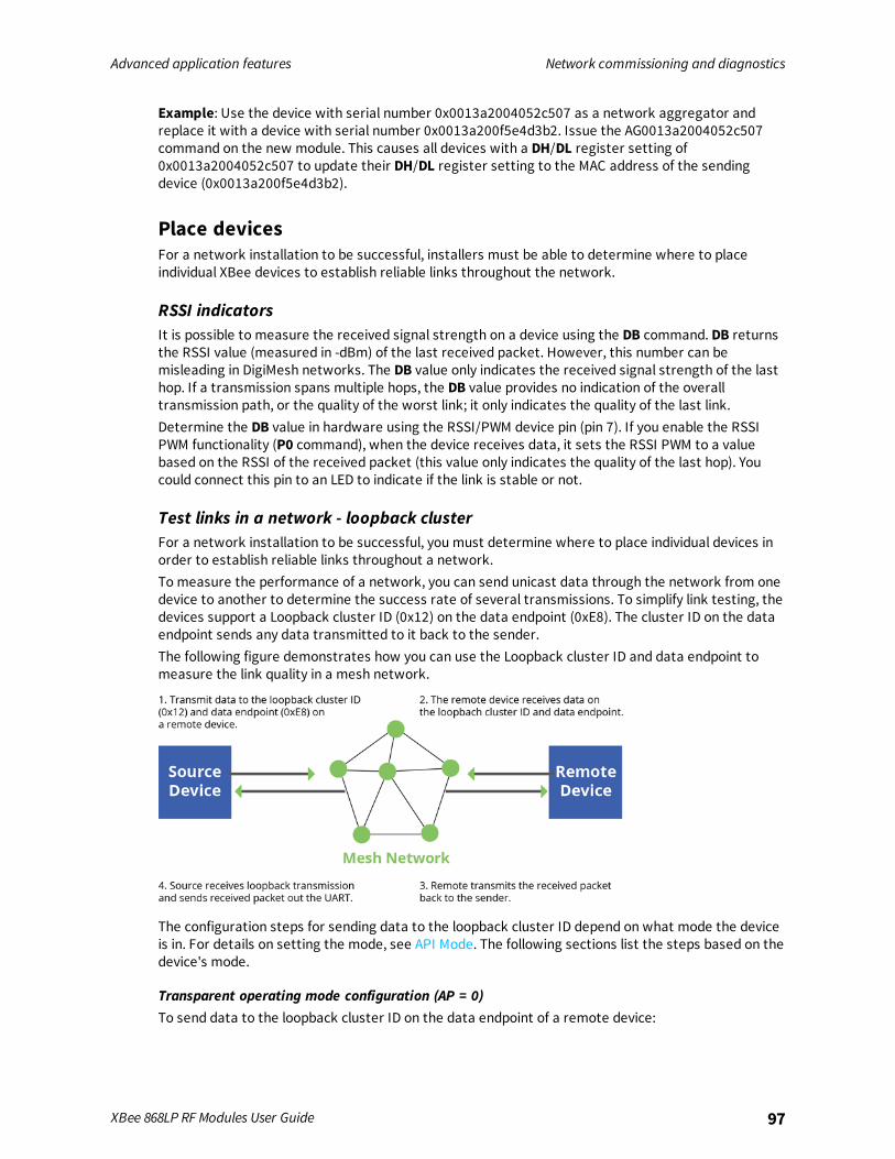
Advanced application features Network commissioning and diagnostics
XBee 868LP RF Modules User Guide 97
Example: Use the device with serial number 0x0013a2004052c507 as a network aggregator andreplace it with a device with serial number 0x0013a200f5e4d3b2. Issue the AG0013a2004052c507command on the new module. This causes all devices with a DH/DL register setting of0x0013a2004052c507 to update their DH/DL register setting to the MAC address of the sendingdevice (0x0013a200f5e4d3b2).
Place devicesFor a network installation to be successful, installers must be able to determine where to placeindividual XBee devices to establish reliable links throughout the network.
RSSI indicatorsIt is possible to measure the received signal strength on a device using the DB command. DB returnsthe RSSI value (measured in -dBm) of the last received packet. However, this number can bemisleading in DigiMesh networks. The DB value only indicates the received signal strength of the lasthop. If a transmission spans multiple hops, the DB value provides no indication of the overalltransmission path, or the quality of the worst link; it only indicates the quality of the last link.Determine the DB value in hardware using the RSSI/PWM device pin (pin 7). If you enable the RSSIPWM functionality (P0 command), when the device receives data, it sets the RSSI PWM to a valuebased on the RSSI of the received packet (this value only indicates the quality of the last hop). Youcould connect this pin to an LED to indicate if the link is stable or not.
Test links in a network - loopback clusterFor a network installation to be successful, you must determine where to place individual devices inorder to establish reliable links throughout a network.To measure the performance of a network, you can send unicast data through the network from onedevice to another to determine the success rate of several transmissions. To simplify link testing, thedevices support a Loopback cluster ID (0x12) on the data endpoint (0xE8). The cluster ID on the dataendpoint sends any data transmitted to it back to the sender.The following figure demonstrates how you can use the Loopback cluster ID and data endpoint tomeasure the link quality in a mesh network.
The configuration steps for sending data to the loopback cluster ID depend on what mode the deviceis in. For details on setting the mode, see API Mode. The following sections list the steps based on thedevice's mode.
Transparent operating mode configuration (AP = 0)To send data to the loopback cluster ID on the data endpoint of a remote device:

Advanced application features Network commissioning and diagnostics
XBee 868LP RF Modules User Guide 98
1. Set the CI command to 0x12.
2. Set the SE and DE commands to 0xE8 (default value).
3. Set the DH and DL commands to the address of the remote (0 for the coordinator, or the 64-bitaddress of the remote).
After exiting Commandmode, the device transmits any serial characters it received to the remotedevice, which returns those characters to the sending device.
API operating mode configuration (AP = 1 or AP = 2)Send an Explicit Addressing Command frame - 0x11 using 0x12 as the cluster ID and 0xE8 as both thesource and destination endpoint.The remote device echoes back the data packets it receives to the sending device.
Device discovery
Network discoveryUse the network discovery command to discover all devices that have joined a network. Issuing theND command sends a broadcast network discovery command throughout the network. All devicesthat receive the command send a response that includes:
n Device addressing information
n Node identifier string (see NI command)
n Other relevant information
You can use this command for generating a list of all module addresses in a network.
Neighbor pollingUse the neighbor poll command to discover the modules which are immediate neighbors (within RFrange) of a particular node. You can use this command to determining network topology anddetermining possible routes.The device issues the command using the FN command. You can initiate the FN command locally on anode using AT commandmode or by using a local AT command request frame. You can also initiate thecommand remotely by sending the target node an FN command using a remote AT command requestAPI frame.A node that executes an FN command sends a broadcast to all of its immediate neighbors. All devicesthat receive this broadcast send an RF packet to the node that initiated the FN command. In aninstance where the device initiates the command remotely, it sends the responses directly to thenode which sent the FN command to the target node. The device outputs the response packet on theinitiating radio in the same format as a network discovery frame.
Link reliabilityTo install a successful mesh network, you must be able to determine where to place individual XBeedevices to establish reliable links throughout the mesh network.
Network link testingTo determine the success rate of many transmissions, send unicast data through the network fromone device to another to measure the performance of the mesh network.
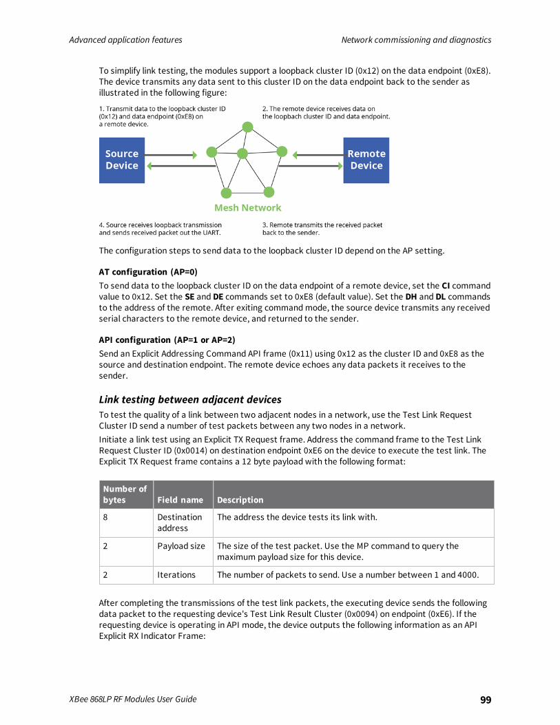
Advanced application features Network commissioning and diagnostics
XBee 868LP RF Modules User Guide 99
To simplify link testing, the modules support a loopback cluster ID (0x12) on the data endpoint (0xE8).The device transmits any data sent to this cluster ID on the data endpoint back to the sender asillustrated in the following figure:
The configuration steps to send data to the loopback cluster ID depend on the AP setting.
AT configuration (AP=0)To send data to the loopback cluster ID on the data endpoint of a remote device, set the CI commandvalue to 0x12. Set the SE and DE commands set to 0xE8 (default value). Set the DH and DL commandsto the address of the remote. After exiting commandmode, the source device transmits any receivedserial characters to the remote device, and returned to the sender.
API configuration (AP=1 or AP=2)Send an Explicit Addressing Command API frame (0x11) using 0x12 as the cluster ID and 0xE8 as thesource and destination endpoint. The remote device echoes any data packets it receives to thesender.
Link testing between adjacent devicesTo test the quality of a link between two adjacent nodes in a network, use the Test Link RequestCluster ID send a number of test packets between any two nodes in a network.Initiate a link test using an Explicit TX Request frame. Address the command frame to the Test LinkRequest Cluster ID (0x0014) on destination endpoint 0xE6 on the device to execute the test link. TheExplicit TX Request frame contains a 12 byte payload with the following format:
Number ofbytes Field name Description
8 Destinationaddress
The address the device tests its link with.
2 Payload size The size of the test packet. Use the MP command to query themaximum payload size for this device.
2 Iterations The number of packets to send. Use a number between 1 and 4000.
After completing the transmissions of the test link packets, the executing device sends the followingdata packet to the requesting device's Test Link Result Cluster (0x0094) on endpoint (0xE6). If therequesting device is operating in API mode, the device outputs the following information as an APIExplicit RX Indicator Frame:
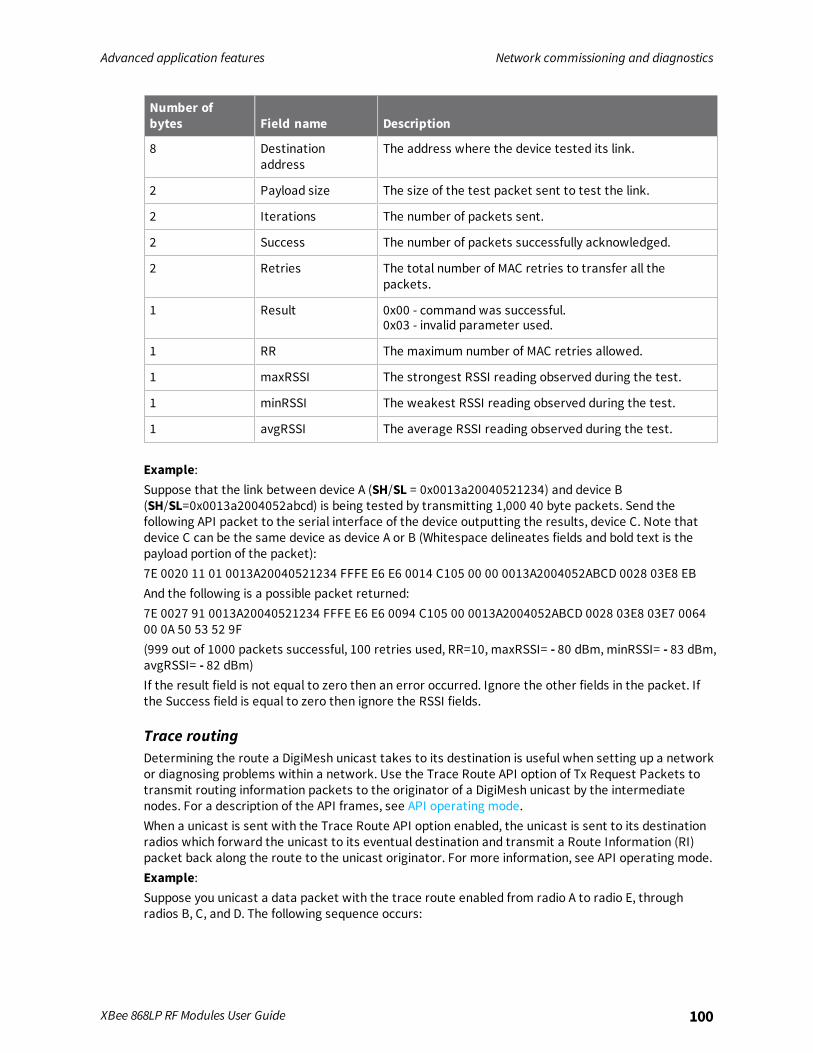
Advanced application features Network commissioning and diagnostics
XBee 868LP RF Modules User Guide 100
Number ofbytes Field name Description
8 Destinationaddress
The address where the device tested its link.
2 Payload size The size of the test packet sent to test the link.
2 Iterations The number of packets sent.
2 Success The number of packets successfully acknowledged.
2 Retries The total number of MAC retries to transfer all thepackets.
1 Result 0x00 - command was successful.0x03 - invalid parameter used.
1 RR The maximum number of MAC retries allowed.
1 maxRSSI The strongest RSSI reading observed during the test.
1 minRSSI The weakest RSSI reading observed during the test.
1 avgRSSI The average RSSI reading observed during the test.
Example:Suppose that the link between device A (SH/SL = 0x0013a20040521234) and device B(SH/SL=0x0013a2004052abcd) is being tested by transmitting 1,000 40 byte packets. Send thefollowing API packet to the serial interface of the device outputting the results, device C. Note thatdevice C can be the same device as device A or B (Whitespace delineates fields and bold text is thepayload portion of the packet):7E 0020 11 01 0013A20040521234 FFFE E6 E6 0014 C105 00 00 0013A2004052ABCD 0028 03E8 EBAnd the following is a possible packet returned:7E 0027 91 0013A20040521234 FFFE E6 E6 0094 C105 00 0013A2004052ABCD 0028 03E8 03E7 006400 0A 50 53 52 9F(999 out of 1000 packets successful, 100 retries used, RR=10, maxRSSI= - 80 dBm, minRSSI= - 83 dBm,avgRSSI= - 82 dBm)If the result field is not equal to zero then an error occurred. Ignore the other fields in the packet. Ifthe Success field is equal to zero then ignore the RSSI fields.
Trace routingDetermining the route a DigiMesh unicast takes to its destination is useful when setting up a networkor diagnosing problems within a network. Use the Trace Route API option of Tx Request Packets totransmit routing information packets to the originator of a DigiMesh unicast by the intermediatenodes. For a description of the API frames, see API operating mode.When a unicast is sent with the Trace Route API option enabled, the unicast is sent to its destinationradios which forward the unicast to its eventual destination and transmit a Route Information (RI)packet back along the route to the unicast originator. For more information, see API operating mode.Example:Suppose you unicast a data packet with the trace route enabled from radio A to radio E, throughradios B, C, and D. The following sequence occurs:
Advanced application features Network commissioning and diagnostics
XBee 868LP RF Modules User Guide 101
n After the successful MAC transmission of the data packet from A to B, A outputs an RI Packetindicating that the transmission of the data packet from A to E was successfully forwarded onehop from A to B.
n After the successful MAC transmission of the data packet from B to C, B transmits a RI Packetto A. Then, A outputs this RI packet out its serial interface.
n After the successful MAC transmission of the data packet from C to D, C transmits a RI Packetto A (through B). Then, A outputs this RI packet out its serial interface.
n After the successful MAC transmission of the data packet from D to E, D transmits an RI Packetto A (through C and B). Then, A outputs this RI packet out its serial interface.
Route Information packets are not guaranteed to arrive in the same order as the unicast packet took.It is also possible Route Information packets that are transferred on a weak route to fail beforearriving at the unicast originator.Because of the large number of Route Information packets that can be generated by a unicast withTrace Route enabled, we suggest that the Trace Route option only be used for occasional diagnosticpurposes and not for normal operations.
NACK messagesTransmit Request (0x10 and 0x11) frames contain a negative-acknowledge character (NACK) APIoption (Bit 2 of the Transmit Options field).If you use this option when transmitting data, when a MAC acknowledgment failure occurs on one ofthe hops to the destination device, the device generates a Route Information Packet (0x8D) frameand sends it to the originator of the unicast.This information is useful because it allows you to identify and repair marginal links.
Commissioning pushbutton and associate LEDXBee devices support a set of commissioning pushbutton and LED behaviors to aid in devicedeployment and commissioning. These include the commissioning push button definitions andassociate LED behaviors. The following features can be supported in hardware:

Advanced application features Network commissioning and diagnostics
XBee 868LP RF Modules User Guide 102
TH RF Module
A pushbutton and an LED can be connected to XBee 868LP RF Module pins 33 and 28 (SMT), or pins 20and 15 (TH) respectively to support the commissioning pushbutton and associate LED functionalities.
Commissioning pushbuttonThe commissioning pushbutton definitions provide a variety of simple functions to help with deployingdevices in a network. Enable the commissioning button functionality on pin 20 by setting the D0command to 1 (enabled by default).
ButtonPresses
Sleepconfiguration and syncstatus Action
1 Not configured for sleep Immediately sends a Node Identification broadcasttransmission.All devices that receive this transmission blink theirAssociate LED rapidly for 1 second. All API devicesthat receive this transmission send a NodeIdentification frame out their serial interface (API ID0x95).
1 Configured for synchronoussleep
Wakes the module for 30 seconds. Immediatelysends a Node Identification broadcast transmission.All devices that receive this transmission blink theirAssociate LED rapidly for 1 second. All API devicesthat receive this transmission send a NodeIdentification frame out their serial interface (API ID0x95).
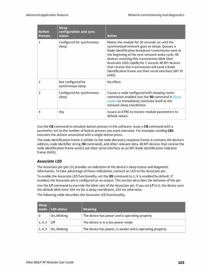
Advanced application features Network commissioning and diagnostics
XBee 868LP RF Modules User Guide 103
ButtonPresses
Sleepconfiguration and syncstatus Action
1 Configured for synchronoussleep
Wakes the module for 30 seconds (or until thesynchronized network goes to sleep). Queues aNode Identification broadcast transmission sent atthe beginning of the next network wake cycle. Alldevices receiving this transmission blink theirAssociate LEDs rapidly for 1 second. All API devicesthat receive this transmission will send a NodeIdentification frame out their serial interface (API ID0x95).
2 Not configured forsynchronous sleep
No effect.
2 Configured for synchronoussleep
Causes a node configured with sleeping routernomination enabled (see the SO command in Sleepmodes to immediately nominate itself as thenetwork sleep coordinator.
4 Any Issues an ATRE to restore module parameters todefault values.
Use the CB command to simulate button presses in the software. Issue a CB command with aparameter set to the number of button presses you want executee. For example, sending CB1executes the actions associated with a single button press.The node identification frame is similar to the node discovery response frame; it contains the device’saddress, node identifier string (NI command), and other relevant data. All API devices that receive thenode identification frame send it out their serial interface as an API Node Identification Indicatorframe (0x95).
Associate LEDThe Associate pin (pin 15) provides an indication of the device's sleep status and diagnosticinformation. To take advantage of these indications, connect an LED to the Associate pin.To enable the Associate LED functionality, set the D5 command to 1; it is enabled by default. Ifenabled, the Associate pin is configured as an output. This section describes the behavior of the pin.Use the LT command to override the blink rate of the Associate pin. If you set LT to 0, the device usesthe default blink time: 500 ms for a sleep coordinator, 250 ms otherwise.The following table describes the Associate LED functionality.
Sleepmode LED status Meaning
0 On, blinking The device has power and is operating properly
1, 4, 5 Off The device is in a low power mode
1, 4, 5 On, blinking The device has power, is awake and is operating properly
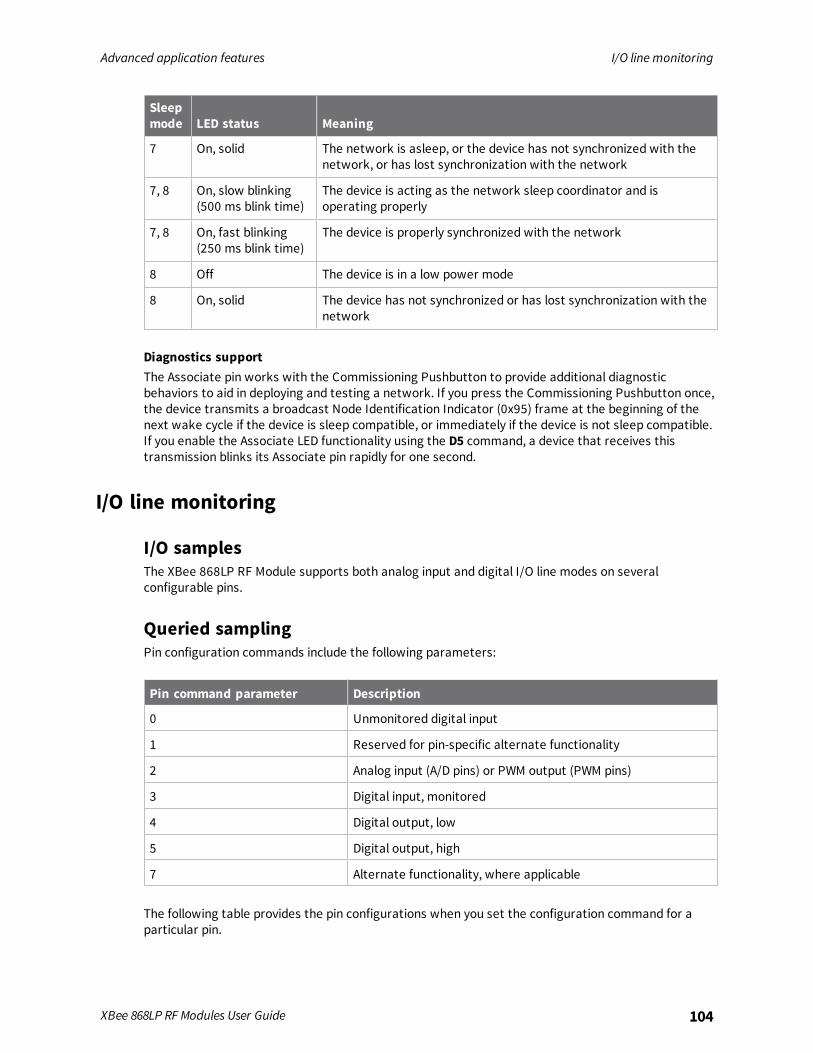
Advanced application features I/O line monitoring
XBee 868LP RF Modules User Guide 104
Sleepmode LED status Meaning
7 On, solid The network is asleep, or the device has not synchronized with thenetwork, or has lost synchronization with the network
7, 8 On, slow blinking(500 ms blink time)
The device is acting as the network sleep coordinator and isoperating properly
7, 8 On, fast blinking(250 ms blink time)
The device is properly synchronized with the network
8 Off The device is in a low power mode
8 On, solid The device has not synchronized or has lost synchronization with thenetwork
Diagnostics supportThe Associate pin works with the Commissioning Pushbutton to provide additional diagnosticbehaviors to aid in deploying and testing a network. If you press the Commissioning Pushbutton once,the device transmits a broadcast Node Identification Indicator (0x95) frame at the beginning of thenext wake cycle if the device is sleep compatible, or immediately if the device is not sleep compatible.If you enable the Associate LED functionality using the D5 command, a device that receives thistransmission blinks its Associate pin rapidly for one second.
I/O line monitoring
I/O samplesThe XBee 868LP RF Module supports both analog input and digital I/O line modes on severalconfigurable pins.
Queried samplingPin configuration commands include the following parameters:
Pin command parameter Description
0 Unmonitored digital input
1 Reserved for pin-specific alternate functionality
2 Analog input (A/D pins) or PWM output (PWM pins)
3 Digital input, monitored
4 Digital output, low
5 Digital output, high
7 Alternate functionality, where applicable
The following table provides the pin configurations when you set the configuration command for aparticular pin.
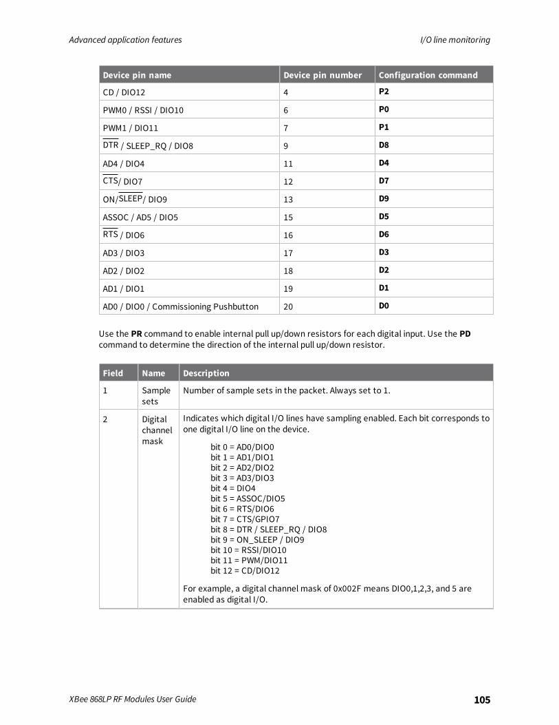
Advanced application features I/O line monitoring
XBee 868LP RF Modules User Guide 105
Device pin name Device pin number Configuration command
CD / DIO12 4 P2
PWM0 / RSSI / DIO10 6 P0
PWM1 / DIO11 7 P1
DTR / SLEEP_RQ / DIO8 9 D8
AD4 / DIO4 11 D4
CTS/ DIO7 12 D7
ON/SLEEP/ DIO9 13 D9
ASSOC / AD5 / DIO5 15 D5
RTS / DIO6 16 D6
AD3 / DIO3 17 D3
AD2 / DIO2 18 D2
AD1 / DIO1 19 D1
AD0 / DIO0 / Commissioning Pushbutton 20 D0
Use the PR command to enable internal pull up/down resistors for each digital input. Use the PDcommand to determine the direction of the internal pull up/down resistor.
Field Name Description
1 Samplesets
Number of sample sets in the packet. Always set to 1.
2 Digitalchannelmask
Indicates which digital I/O lines have sampling enabled. Each bit corresponds toone digital I/O line on the device.
bit 0 = AD0/DIO0bit 1 = AD1/DIO1bit 2 = AD2/DIO2bit 3 = AD3/DIO3bit 4 = DIO4bit 5 = ASSOC/DIO5bit 6 = RTS/DIO6bit 7 = CTS/GPIO7bit 8 = DTR / SLEEP_RQ / DIO8bit 9 = ON_SLEEP / DIO9bit 10 = RSSI/DIO10bit 11 = PWM/DIO11bit 12 = CD/DIO12
For example, a digital channel mask of 0x002F means DIO0,1,2,3, and 5 areenabled as digital I/O.

Advanced application features I/O line monitoring
XBee 868LP RF Modules User Guide 106
Field Name Description
1 Analogchannelmask
Indicates which lines have analog inputs enabled for sampling. Each bit in theanalog channel mask corresponds to one analog input channel.
bit 0 = AD0/DIO0bit 1 = AD1/DIO1bit 2 = AD2/DIO2bit 3 = AD3/DIO3bit 4 = AD4/DIO4bit 5 = ASSOC/AD5/DIO5
Variable Sampleddata set
If you enable any digital I/O lines, the first two bytes of the data set indicatethe state of all enabled digital I/O.Only digital channels that you enable in the Digital channel mask bytes haveany meaning in the sample set. If do not enable any digital I/O on the device, itomits these two bytes.Following the digital I/O data (if there is any), each enabled analog channelreturns two bytes. The data starts with AIN0 and continues sequentially foreach enabled analog input channel up to AIN5.
If you issue the IS command using an Commandmode, the device returns a carriage return delimitedlist containing the fields in the previous list. If you issue a command via an API frame, the devicereturns an AT command response API frame with the I/O data included in the command data portionof the packet.
Example Sample AT response
0x01 [1 sample set]
0x0C0C [Digital Inputs: DIO 2, 3, 10, 11 enabled]
0x03 [Analog Inputs: A/D 0, 1 enabled]
0x0408 [Digital input states: DIO 3, 10 high, DIO 2, 11 low]
0x03D0 [Analog input: ADIO 0 = 0x3D0]
0x0124 [Analog input: ADIO 1 =0x120]
Periodic I/O samplingPeriodic sampling allows a device to take an I/O sample and transmit it to a remote device at aperiodic rate. Use the IR command to set the periodic sample rate.
n To disable periodic sampling, set IR to 0.
n For all other IR values, the firmware samples data when IRmilliseconds elapse and the sampledata transmits to a remote device.
The DH and DL commands determine the destination address of the I/O samples.Only devices with API operating mode enabled send I/O data samples out their serial interface.Devices that are in Transparent mode (AP = 0) discard the I/O data samples they receive.A device with sleep enabled transmits periodic I/O samples at the IR rate until the ST time expires andthe device can resume sleeping. For more information about setting sleepmodes, see Sleepmodes.

Advanced application features General Purpose Flash Memory
XBee 868LP RF Modules User Guide 107
Detect digital I/O changesYou can configure devices to transmit a data sample immediately whenever a monitored digital I/Opin changes state. The IC command is a bitmask that you use to set which digital I/O lines to monitorfor a state change. If you set one or more bits in IC, the device transmits an I/O sample as soon itobserves a state change in one of the monitored digital I/O lines using edge detection.The figure below shows how I/O change detection can work with periodic sampling.
Enabling edge detection forces an immediate sample of all monitored digital I/O lines if any digital I/Olines change state.
General Purpose Flash MemoryXBee 868LP RF Modules provide 119 512-byte blocks of flash memory that an application can read andwrite to. This memory provides a non-volatile data storage area that an application uses for manypurposes. Some common uses of this data storage include:
n Storing logged sensor data
n Buffering firmware update data for a host microcontroller
n Storing and retrieving data tables needed for calculations performed by a host microcontroller
The General Purpose Memory (GPM) is also used to store a firmware update file for over-the-airfirmware updates of the device itself.
Access General Purpose Flash MemoryTo access the GPM of a target node locally or over-the-air, send commands to the MEMORY_ACCESScluster ID (0x23) on the DIGI_DEVICE endpoint (0xE6) of the target node using explicit API frames. Fora description of Explicit API frames, see Operate in API mode.To issue a GPM command, format the payload of an explicit API frame as follows:
Byte offsetin payload
Number ofbytes Field name General field description
0 1 GPM_CMD_ID Specific GPM commands are describedin detail in the topics that follow.
1 1 GPM_OPTIONS Command-specific options.
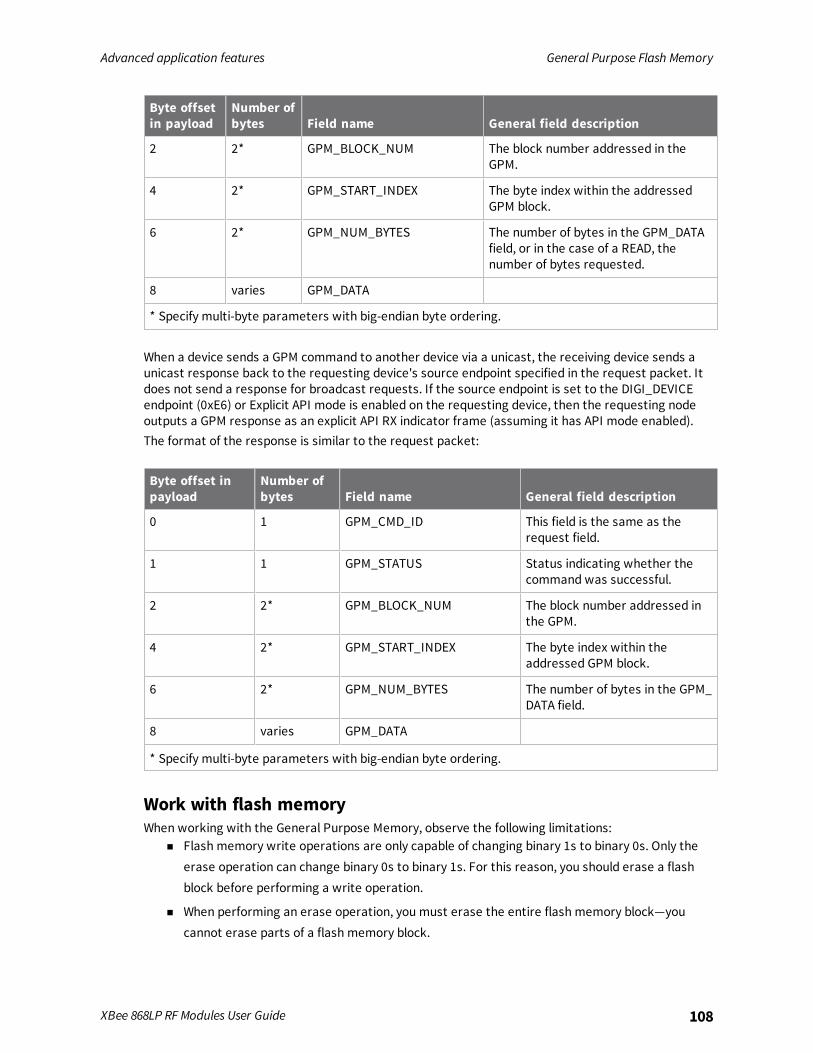
Advanced application features General Purpose Flash Memory
XBee 868LP RF Modules User Guide 108
Byte offsetin payload
Number ofbytes Field name General field description
2 2* GPM_BLOCK_NUM The block number addressed in theGPM.
4 2* GPM_START_INDEX The byte index within the addressedGPM block.
6 2* GPM_NUM_BYTES The number of bytes in the GPM_DATAfield, or in the case of a READ, thenumber of bytes requested.
8 varies GPM_DATA
* Specify multi-byte parameters with big-endian byte ordering.
When a device sends a GPM command to another device via a unicast, the receiving device sends aunicast response back to the requesting device's source endpoint specified in the request packet. Itdoes not send a response for broadcast requests. If the source endpoint is set to the DIGI_DEVICEendpoint (0xE6) or Explicit API mode is enabled on the requesting device, then the requesting nodeoutputs a GPM response as an explicit API RX indicator frame (assuming it has API mode enabled).The format of the response is similar to the request packet:
Byte offset inpayload
Number ofbytes Field name General field description
0 1 GPM_CMD_ID This field is the same as therequest field.
1 1 GPM_STATUS Status indicating whether thecommand was successful.
2 2* GPM_BLOCK_NUM The block number addressed inthe GPM.
4 2* GPM_START_INDEX The byte index within theaddressed GPM block.
6 2* GPM_NUM_BYTES The number of bytes in the GPM_DATA field.
8 varies GPM_DATA
* Specify multi-byte parameters with big-endian byte ordering.
Work with flash memoryWhen working with the General Purpose Memory, observe the following limitations:
n Flash memory write operations are only capable of changing binary 1s to binary 0s. Only theerase operation can change binary 0s to binary 1s. For this reason, you should erase a flashblock before performing a write operation.
n When performing an erase operation, you must erase the entire flash memory block—youcannot erase parts of a flash memory block.
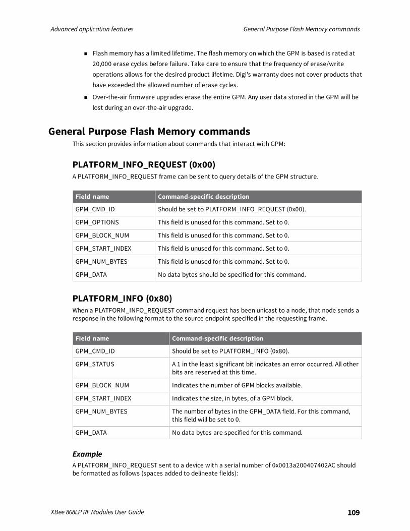
Advanced application features General Purpose Flash Memory commands
XBee 868LP RF Modules User Guide 109
n Flash memory has a limited lifetime. The flash memory on which the GPM is based is rated at20,000 erase cycles before failure. Take care to ensure that the frequency of erase/writeoperations allows for the desired product lifetime. Digi's warranty does not cover products thathave exceeded the allowed number of erase cycles.
n Over-the-air firmware upgrades erase the entire GPM. Any user data stored in the GPM will belost during an over-the-air upgrade.
General Purpose Flash Memory commandsThis section provides information about commands that interact with GPM:
PLATFORM_INFO_REQUEST (0x00)A PLATFORM_INFO_REQUEST frame can be sent to query details of the GPM structure.
Field name Command-specific description
GPM_CMD_ID Should be set to PLATFORM_INFO_REQUEST (0x00).
GPM_OPTIONS This field is unused for this command. Set to 0.
GPM_BLOCK_NUM This field is unused for this command. Set to 0.
GPM_START_INDEX This field is unused for this command. Set to 0.
GPM_NUM_BYTES This field is unused for this command. Set to 0.
GPM_DATA No data bytes should be specified for this command.
PLATFORM_INFO (0x80)When a PLATFORM_INFO_REQUEST command request has been unicast to a node, that node sends aresponse in the following format to the source endpoint specified in the requesting frame.
Field name Command-specific description
GPM_CMD_ID Should be set to PLATFORM_INFO (0x80).
GPM_STATUS A 1 in the least significant bit indicates an error occurred. All otherbits are reserved at this time.
GPM_BLOCK_NUM Indicates the number of GPM blocks available.
GPM_START_INDEX Indicates the size, in bytes, of a GPM block.
GPM_NUM_BYTES The number of bytes in the GPM_DATA field. For this command,this field will be set to 0.
GPM_DATA No data bytes are specified for this command.
ExampleA PLATFORM_INFO_REQUEST sent to a device with a serial number of 0x0013a200407402AC shouldbe formatted as follows (spaces added to delineate fields):

Advanced application features General Purpose Flash Memory commands
XBee 868LP RF Modules User Guide 110
7E 001C 11 01 0013A200407402AC FFFE E6 E6 0023 C105 00 00 00 00 0000 0000 0000 24Assuming all transmissions were successful, the following API packets would be output the sourcenode's serial interface:
7E 0007 8B 01 FFFE 00 00 00 767E 001A 91 0013A200407402AC FFFE E6 E6 0023 C105 C1 80 00 0077 0200 0000 EB
ERASE (0x01)The ERASE command erases (writes all bits to binary 1) one or all of the GPM flash blocks. You can alsouse the ERASE command to erase all blocks of the GPM by setting the GPM_NUM_BYTES field to 0.
Field name Command-specific description
GPM_CMD_ID Should be set to ERASE (0x01).
GPM_OPTIONS There are currently no options defined for the ERASE command.Set this field to 0.
GPM_BLOCK_NUM Set to the index of the GPM block that should be erased. Whenerasing all GPM blocks, this field is ignored (set to 0).
GPM_START_INDEX The ERASE command only works on complete GPM blocks. Thecommand cannot be used to erase part of a GPM block. For thisreason GPM_START_INDEX is unused (set to 0).
GPM_NUM_BYTES Setting GPM_NUM_BYTES to 0 has a special meaning. It indicatesthat every flash block in the GPM should be erased (not just theone specified with GPM_BLOCK_NUM). In all other cases, theGPM_NUM_BYTES field should be set to the GPM flash block size.
GPM_DATA No data bytes are specified for this command.
ERASE_RESPONSE (0x81)When an ERASE command request has been unicast to a node, that node sends a response in thefollowing format to the source endpoint specified in the requesting frame.
Field name Command-specific description
GPM_CMD_ID Should be set to ERASE_RESPONSE (0x81).
GPM_STATUS A 1 in the least significant bit indicates an error occurred. Allother bits are reserved at this time.
GPM_BLOCK_NUM Matches the parameter passed in the request frame.
GPM_START_INDEX Matches the parameter passed in the request frame.
GPM_NUM_BYTES The number of bytes in the GPM_DATA field. For this command,this field will be set to 0.
GPM_DATA No data bytes are specified for this command.
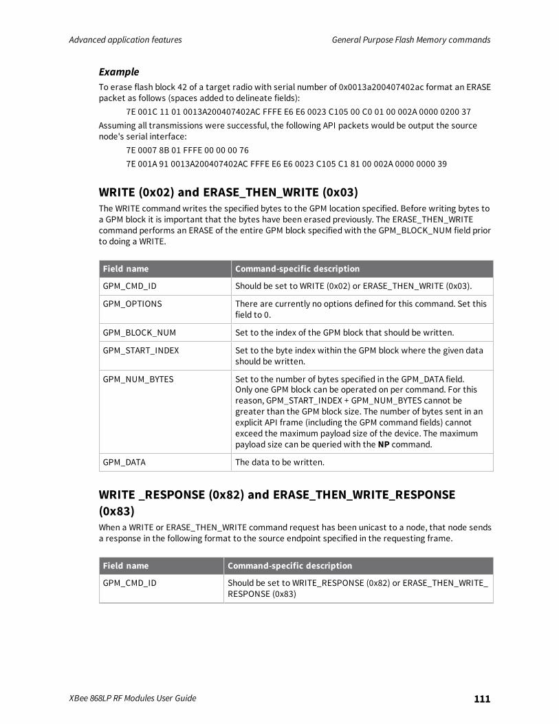
Advanced application features General Purpose Flash Memory commands
XBee 868LP RF Modules User Guide 111
ExampleTo erase flash block 42 of a target radio with serial number of 0x0013a200407402ac format an ERASEpacket as follows (spaces added to delineate fields):
7E 001C 11 01 0013A200407402AC FFFE E6 E6 0023 C105 00 C0 01 00 002A 0000 0200 37Assuming all transmissions were successful, the following API packets would be output the sourcenode's serial interface:
7E 0007 8B 01 FFFE 00 00 00 767E 001A 91 0013A200407402AC FFFE E6 E6 0023 C105 C1 81 00 002A 0000 0000 39
WRITE (0x02) and ERASE_THEN_WRITE (0x03)The WRITE command writes the specified bytes to the GPM location specified. Before writing bytes toa GPM block it is important that the bytes have been erased previously. The ERASE_THEN_WRITEcommand performs an ERASE of the entire GPM block specified with the GPM_BLOCK_NUM field priorto doing a WRITE.
Field name Command-specific description
GPM_CMD_ID Should be set to WRITE (0x02) or ERASE_THEN_WRITE (0x03).
GPM_OPTIONS There are currently no options defined for this command. Set thisfield to 0.
GPM_BLOCK_NUM Set to the index of the GPM block that should be written.
GPM_START_INDEX Set to the byte index within the GPM block where the given datashould be written.
GPM_NUM_BYTES Set to the number of bytes specified in the GPM_DATA field.Only one GPM block can be operated on per command. For thisreason, GPM_START_INDEX + GPM_NUM_BYTES cannot begreater than the GPM block size. The number of bytes sent in anexplicit API frame (including the GPM command fields) cannotexceed the maximum payload size of the device. The maximumpayload size can be queried with the NP command.
GPM_DATA The data to be written.
WRITE _RESPONSE (0x82) and ERASE_THEN_WRITE_RESPONSE(0x83)When a WRITE or ERASE_THEN_WRITE command request has been unicast to a node, that node sendsa response in the following format to the source endpoint specified in the requesting frame.
Field name Command-specific description
GPM_CMD_ID Should be set to WRITE_RESPONSE (0x82) or ERASE_THEN_WRITE_RESPONSE (0x83)
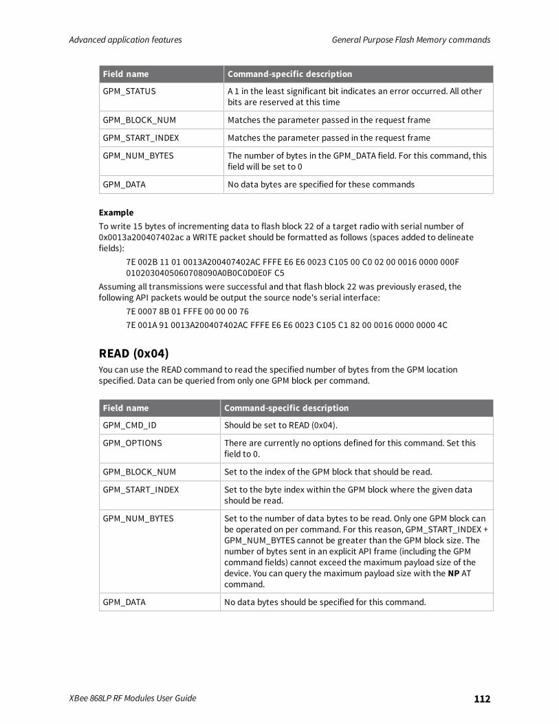
Advanced application features General Purpose Flash Memory commands
XBee 868LP RF Modules User Guide 112
Field name Command-specific description
GPM_STATUS A 1 in the least significant bit indicates an error occurred. All otherbits are reserved at this time
GPM_BLOCK_NUM Matches the parameter passed in the request frame
GPM_START_INDEX Matches the parameter passed in the request frame
GPM_NUM_BYTES The number of bytes in the GPM_DATA field. For this command, thisfield will be set to 0
GPM_DATA No data bytes are specified for these commands
ExampleTo write 15 bytes of incrementing data to flash block 22 of a target radio with serial number of0x0013a200407402ac a WRITE packet should be formatted as follows (spaces added to delineatefields):
7E 002B 11 01 0013A200407402AC FFFE E6 E6 0023 C105 00 C0 02 00 0016 0000 000F0102030405060708090A0B0C0D0E0F C5
Assuming all transmissions were successful and that flash block 22 was previously erased, thefollowing API packets would be output the source node's serial interface:
7E 0007 8B 01 FFFE 00 00 00 767E 001A 91 0013A200407402AC FFFE E6 E6 0023 C105 C1 82 00 0016 0000 0000 4C
READ (0x04)You can use the READ command to read the specified number of bytes from the GPM locationspecified. Data can be queried from only one GPM block per command.
Field name Command-specific description
GPM_CMD_ID Should be set to READ (0x04).
GPM_OPTIONS There are currently no options defined for this command. Set thisfield to 0.
GPM_BLOCK_NUM Set to the index of the GPM block that should be read.
GPM_START_INDEX Set to the byte index within the GPM block where the given datashould be read.
GPM_NUM_BYTES Set to the number of data bytes to be read. Only one GPM block canbe operated on per command. For this reason, GPM_START_INDEX +GPM_NUM_BYTES cannot be greater than the GPM block size. Thenumber of bytes sent in an explicit API frame (including the GPMcommand fields) cannot exceed the maximum payload size of thedevice. You can query the maximum payload size with the NP ATcommand.
GPM_DATA No data bytes should be specified for this command.

Advanced application features General Purpose Flash Memory commands
XBee 868LP RF Modules User Guide 113
READ_RESPONSE (0x84)When a READ command request has been unicast to a node, that node sends a response in thefollowing format to the source endpoint specified in the requesting frame.
Field name Command-specific description
GPM_CMD_ID Should be set to READ_RESPONSE (0x84).
GPM_STATUS A 1 in the least significant bit indicates an error occurred. All otherbits are reserved at this time.
GPM_BLOCK_NUM Matches the parameter passed in the request frame.
GPM_START_INDEX Matches the parameter passed in the request frame.
GPM_NUM_BYTES The number of bytes in the GPM_DATA field.
GPM_DATA The bytes read from the GPM block specified.
ExampleTo read 15 bytes of previously written data from flash block 22 of a target radio with serial number of0x0013a200407402ac a READ packet should be formatted as follows (spaces added to delineatefields):
7E 001C 11 01 0013A200407402AC FFFE E6 E6 0023 C105 00 C0 04 00 0016 0000 000F 3BAssuming all transmissions were successful and that flash block 22 was previously written withincrementing data, the following API packets would be output the source node's serial interface:
7E 0007 8B 01 FFFE 00 00 00 767E 0029 91 0013A200407402AC FFFE E6 E6 0023 C105 C1 84 00 0016 0000 000F0102030405060708090A0B0C0D0E0F C3
FIRMWARE_VERIFY (0x05) and FIRMWARE_VERIFY_AND_INSTALL(0x06)Use the FIRMWARE_VERIFY and FIRMWARE_VERIFY_AND_INSTALL commands when remotelyupdating firmware on a device. For more inoformation about firmware updates. These commandscheck if the GPM contains a valid over-the-air update file. For the FIRMWARE_VERIFY_AND_INSTALLcommand, if the GPM contains a valid firmware image then the device resets and begins using thenew firmware.
Field name Command-specific description
GPM_CMD_ID Should be set to FIRMWARE_VERIFY (0x05) or FIRMWARE_VERIFY_AND_INSTALL (0x06)
GPM_OPTIONS There are currently no options defined for this command. Setthis field to 0.
GPM_BLOCK_NUM This field is unused for this command. Set to 0.
GPM_START_INDEX This field is unused for this command. Set to 0.

Advanced application features General Purpose Flash Memory commands
XBee 868LP RF Modules User Guide 114
Field name Command-specific description
GPM_NUM_BYTES This field is unused for this command. Set to 0.
GPM_DATA This field is unused for this command
FIRMWARE_VERIFY_RESPONSE (0x85)When a FIRMWARE_VERIFY command request has been unicast to a node, that node sends a responsein the following format to the source endpoint specified in the requesting frame.
Field name Command-specific description
GPM_CMD_ID Should be set to FIRMWARE_VERIFY_RESPONSE (0x85)
GPM_STATUS A 1 in the least significant bit indicates the GPM does not contain avalid firmware image. A 0 in the least significant bit indicates theGPM does contain a valid firmware image. All other bits arereserved at this time.
GPM_BLOCK_NUM This field is unused for this command. Set to 0.
GPM_START_INDEX This field is unused for this command. Set to 0.
GPM_NUM_BYTES This field is unused for this command. Set to 0.
GPM_DATA This field is unused for this command
FIRMWARE_VERIFY _AND_INSTALL_RESPONSE (0x86)When a FIRMWARE_VERIFY_AND_INSTALL command request has been unicast to a node, that nodesends a response in the following format to the source endpoint specified in the requesting frame onlyif the GPM memory does not contain a valid image. If the image is valid, the device resets and beginsusing the new firmware.
Field name Command-specific description
GPM_CMD_ID Should be set to FIRMWARE_VERIFY_AND_INSTALL_RESPONSE(0x86).
GPM_STATUS A 1 in the least significant bit indicates the GPM does not contain avalid firmware image. All other bits are reserved at this time.
GPM_BLOCK_NUM This field is unused for this command. Set to 0.
GPM_START_INDEX This field is unused for this command. Set to 0.
GPM_NUM_BYTES This field is unused for this command. Set to 0.
GPM_DATA This field is unused for this command.
ExampleTo verify a firmware image previously loaded into the GPM on a target device with serial number0x0013a200407402ac, format a FIRMWARE_VERIFY packet as follows (spaces added to delineatefields):

Advanced application features Over-the-air firmware updates
XBee 868LP RF Modules User Guide 115
7E 001C 11 01 0013A200407402AC FFFE E6 E6 0023 C105 00 00 05 00 0000 0000 0000 1FAssuming all transmissions were successful and that the firmware image previously loaded into theGPM is valid, the following API packets would be output the source node's serial interface:
7E 0007 8B 01 FFFE 00 00 00 767E 001A 91 0013A200407402AC FFFE E6 E6 0023 C105 C1 85 00 0000 0000 0000 5F
Over-the-air firmware updatesThere are two methods of updating the firmware on the device. You can update the firmware locallywith XCTU using the device's serial port interface. You can also update firmware using the device's RFinterface (over-the-air updating.)The over-the-air firmware update method provided is a robust and versatile technique that you cantailor to many different networks and applications. OTA updates are reliable andminimize disruptionof normal network operations.In the following sections, we refer to the node that will be updated as the target node. We refer to thenode providing the update information as the source node. In most applications the source node islocally attached to a computer running update software.There are three phases of the over-the-air update process:
1. Distribute the new application
2. Verify the new application
3. Install the application
Distribute the new applicationThe first phase of performing an over-the-air update on a device is transferring the new firmware fileto the target node. Load the new firmware image in the target node's GPM prior to installation. XBee868LP RF Modules use an encrypted binary (.ebin) file for both serial and over-the-air firmwareupdates. These firmware files are available on the Digi Support website and via XCTU.Send the contents of the .ebin file to the target device using general purpose memory WRITEcommands. Erase the entire GPM prior to beginning an upload of an .ebin file. The contents of the .ebinfile should be stored in order in the appropriate GPM memory blocks. The number of bytes that aresent in an individual GPM WRITE frame is flexible and can be catered to the user application.
ExampleThe example firmware version has an .ebin file of 55,141 bytes in length. Based on network traffic, wedetermine that sending a 128 byte packet every 30 seconds minimizes network disruption. For thisreason, you would divide and address the .ebin as follows:
GPM_BLOCK_NUM GPM_START_INDEX GPM_NUM_BYTES .ebin bytes
0 0 128 0 to 127
0 128 128 128 to 255
0 256 128 256 to 383
0 384 128 384 to 511
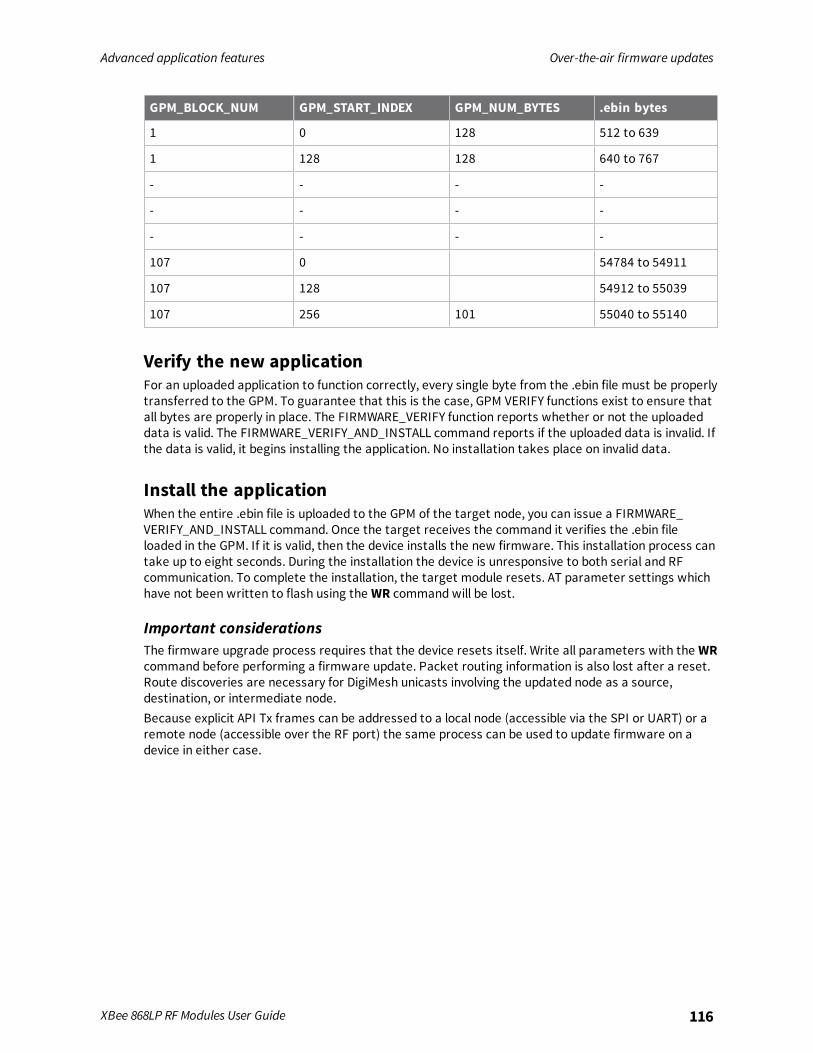
Advanced application features Over-the-air firmware updates
XBee 868LP RF Modules User Guide 116
GPM_BLOCK_NUM GPM_START_INDEX GPM_NUM_BYTES .ebin bytes
1 0 128 512 to 639
1 128 128 640 to 767
- - - -
- - - -
- - - -
107 0 54784 to 54911
107 128 54912 to 55039
107 256 101 55040 to 55140
Verify the new applicationFor an uploaded application to function correctly, every single byte from the .ebin file must be properlytransferred to the GPM. To guarantee that this is the case, GPM VERIFY functions exist to ensure thatall bytes are properly in place. The FIRMWARE_VERIFY function reports whether or not the uploadeddata is valid. The FIRMWARE_VERIFY_AND_INSTALL command reports if the uploaded data is invalid. Ifthe data is valid, it begins installing the application. No installation takes place on invalid data.
Install the applicationWhen the entire .ebin file is uploaded to the GPM of the target node, you can issue a FIRMWARE_VERIFY_AND_INSTALL command. Once the target receives the command it verifies the .ebin fileloaded in the GPM. If it is valid, then the device installs the new firmware. This installation process cantake up to eight seconds. During the installation the device is unresponsive to both serial and RFcommunication. To complete the installation, the target module resets. AT parameter settings whichhave not been written to flash using the WR command will be lost.
Important considerationsThe firmware upgrade process requires that the device resets itself. Write all parameters with the WRcommand before performing a firmware update. Packet routing information is also lost after a reset.Route discoveries are necessary for DigiMesh unicasts involving the updated node as a source,destination, or intermediate node.Because explicit API Tx frames can be addressed to a local node (accessible via the SPI or UART) or aremote node (accessible over the RF port) the same process can be used to update firmware on adevice in either case.
Networking methods
This section explains the basic layers and the three networking methods available on the XBee 868LPRF Modules, building from the simplest to the most complex.
Directed Broadcast/Repeater mode 118Point to Point/Multipoint mode 118DigiMesh networking 118Networking concepts 120Data transmission and routing 120
XBee 868LP RF Modules User Guide 117
Networking methods Directed Broadcast/Repeater mode
XBee 868LP RF Modules User Guide 118
Directed Broadcast/Repeater modeIn this broadcast mode, the exact transmission method is determined by the data rate of your device.
n In the 10k version, set the network in a repeater mode, where there is no route discovery. Thetransmission is sent out to the network and each device repeats the message to itsneighboring devices. There is no route discovery in this method.
n In the 80k version of the device, the transmission is directed to a specific media access control(MAC) address, using a route discovered by a router device. In both methods, all transmissionsare broadcast messages, not unicast messages.
Point to Point/Multipoint modeIn this mode, there is a permanent link between two endpoints. Switched point-to-point topologiesare the basic model of conventional telephony. The value of a permanent point-to-point network isunimpeded communications between the two endpoints. The value of an on-demand point-to-pointconnection is proportional to the number of potential pairs of subscribers.
Permanent (dedicated)One of the variations of point-to-point topology is a point-to-point communications channel thatappears, to the user, to be permanently associated with the two endpoints. Within many switchedtelecommunications systems, it is possible to establish a permanent circuit. One example might be atelephone in the lobby of a public building that is programmed to ring only the number of a telephonedispatcher. “Nailing down” a switched connection saves the cost of running a physical circuit betweenthe two points. The resources in such a connection can be released when it is no longer needed.
SwitchedUsing circuit-switching or packet-switching technologies, you can set up a point-to-point circuitdynamically and dropped when no longer needed.
DigiMesh networkingA mesh network is a topology in which each node in the network is connected to other nodes aroundit. Each node cooperates in transmitting information. Mesh networking provides these importantbenefits:
n Routing. With this technique, the message is propagated along a path by hopping from node tonode until it reaches its final destination.
n Ad-hoc network creation. This is an automated process that creates an entire network ofnodes on the fly, without any human intervention.
n Self-healing. This process automatically figures out if one or more nodes on the network ismissing and reconfigures the network to repair any broken routes.
n Peer-to-peer architecture. No hierarchy and no parent-child relationships are needed.
n Quiet protocol. Routing overhead will be reduced by using a reactive protocol similar to AODV.
n Route discovery. Rather than maintaining a network map, routes will be discovered andcreated only when needed.
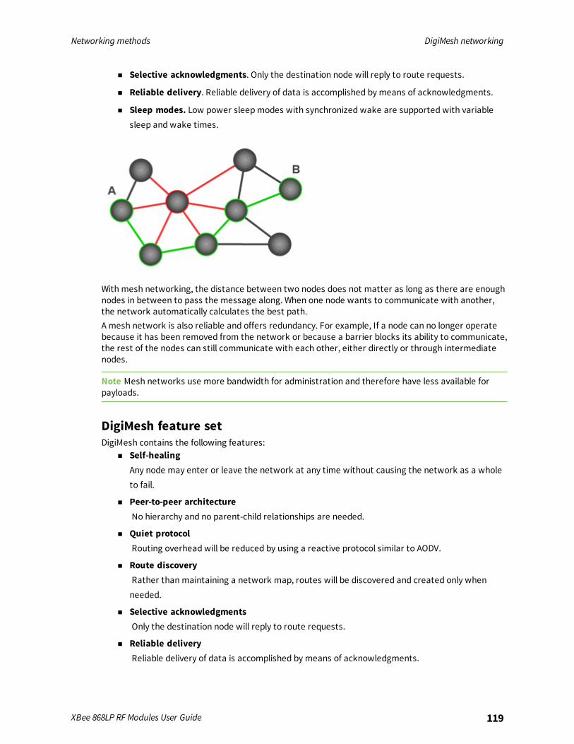
Networking methods DigiMesh networking
XBee 868LP RF Modules User Guide 119
n Selective acknowledgments. Only the destination node will reply to route requests.
n Reliable delivery. Reliable delivery of data is accomplished by means of acknowledgments.
n Sleep modes. Low power sleepmodes with synchronized wake are supported with variablesleep and wake times.
With mesh networking, the distance between two nodes does not matter as long as there are enoughnodes in between to pass the message along. When one node wants to communicate with another,the network automatically calculates the best path.A mesh network is also reliable and offers redundancy. For example, If a node can no longer operatebecause it has been removed from the network or because a barrier blocks its ability to communicate,the rest of the nodes can still communicate with each other, either directly or through intermediatenodes.
Note Mesh networks use more bandwidth for administration and therefore have less available forpayloads.
DigiMesh feature setDigiMesh contains the following features:
n Self-healingAny node may enter or leave the network at any time without causing the network as a wholeto fail.
n Peer-to-peer architectureNo hierarchy and no parent-child relationships are needed.
n Quiet protocolRouting overhead will be reduced by using a reactive protocol similar to AODV.
n Route discoveryRather than maintaining a network map, routes will be discovered and created only whenneeded.
n Selective acknowledgmentsOnly the destination node will reply to route requests.
n Reliable deliveryReliable delivery of data is accomplished by means of acknowledgments.
Networking methods Networking concepts
XBee 868LP RF Modules User Guide 120
n Sleep modesLow power sleepmodes with synchronized wake are supported with variable sleep and waketimes.
Networking conceptsThis section provides information on configuring DigiMesh devices and network identifiers.
Device ConfigurationYou can configure DigiMesh devices to act as routers or end devices with the CE command. By default,all devices in a DigiMesh network act as routers. Devices configured as routers actively relay networkunicast and broadcast traffic.
Network IDDigiMesh networks are defined with a unique network identifier. Set the identifier using the IDcommand. For devices to communicate they must be configured with the same network identifier.The ID parameter allows multiple DigiMesh networks to co-exist on the same physical channel.
Data transmission and routingThis section provides information on data transmission, routing, throughput, and transmissiontimeouts.
Unicast addressingWhen devices transmit using DigiMesh unicast, the network uses retries and acknowledgments(ACKs) for reliable data delivery. In a retry and acknowledgment scheme, for every data packet that adevice sends, the receiving device must send an acknowledgment back to the transmitting device tolet the sender know that the data packet arrived at the receiver. If the transmitting device does notreceive an acknowledgment then it re-sends the packet. It sends the packet a finite number of timesbefore the system times out.The MR (Mesh Network Retries) parameter determines the number of mesh network retries. Thesender device transmits RF data packets up toMR + 1 times across the network route, and thereceiver transmits ACKs when it receives the packet. If the sender does not receive a network ACKwithin the time it takes for a packet to traverse the network twice, the sender retransmits thepacket.To send unicast messages while in Transparent operating mode, set the DH and DL on thetransmitting device to match the corresponding SH and SL parameter values on the receiving device.
Broadcast addressingAll of the routers in a network receive and repeat broadcast transmissions. Broadcast transmissionsdo not use ACKs, so the sending device sends the broadcast multiple times. By default, the sendingdevice sends a broadcast transmission four times. The transmissions become automatic retrieswithout acknowledgments. This results in all nodes repeating the transmission four times as well.In order to avoid RF packet collisions, the network inserts a random delay before each router relaysthe broadcast message. You can change this random delay time with the NN parameter.
Networking methods Data transmission and routing
XBee 868LP RF Modules User Guide 121
Sending frequent broadcast transmissions can quickly reduce the available network bandwidth. Usebroadcast transmissions sparingly.The broadcast address is a 64 bit address with the lowest 16 bits set to 1. The upper bits are set to 0.To send a broadcast transmission:
n Set DH to 0.
n Set DL to 0xFFFF.
In API operating mode, this sets the destination address to 0x000000000000FFFF.
RoutingDevices within a mesh network determine reliable routes using a routing algorithm and table. Therouting algorithm uses a reactive method derived from Ad-hoc On-demand Distance Vector (AODV).The device uses an associative routing table to map a destination node address with its next hop. Bysending a message to the next hop address, the message reaches its destination or is forwarded toan intermediate router which routes the message on to its destination.The device broadcasts a message with a broadcast address to all neighbors. All routers receiving themessage rebroadcast the message MT+1 times and eventually the message reaches all corners of thenetwork. Packet tracking prevents a node from resending a broadcast message more thanMT+1times.
Route discoveryRoute discovery is a process that occurs when:
1. The source node does not have a route to the requested destination.
2. A route fails. This happens when the source node uses up its network retries without receivingan ACK.
Route discovery begins by the source node broadcasting a route request (RREQ). We call any routerthat receives the RREQ and is not the ultimate destination, an intermediate node.Intermediate nodes may either drop or forward a RREQ, depending on whether the new RREQ has abetter route back to the source node. If so, the node saves, updates and broadcasts the RREQ.When the ultimate destination receives the RREQ, it unicasts a route reply (RREP) back to the sourcenode along the path of the RREQ. It does this regardless of route quality and regardless of how manytimes it has seen an RREQ before.This allows the source node to receive multiple route replies. The source node selects the route withthe best round trip route quality, which it uses for the queued packet and for subsequent packets withthe same destination address.
DigiMesh throughputThroughput in a DigiMesh network can vary due to a number of variables, including:
n The number of hops.
n If you enable or disable encryption.
n Sleeping end devices.
n Failures and route discoveries.
The results apply to the 80 kb/s version, 115.2 kb/s serial data rate, 100 KB.

Networking methods Data transmission and routing
XBee 868LP RF Modules User Guide 122
Configuration Data throughput
Mesh unicast, 1 hop, encryption disabled 35.6 kb/s
Mesh unicast, 3 hop, encryption disabled 11.9 kb/s
Mesh unicast, 6 hop, encryption disabled 7.1 kb/s
Mesh unicast, 1 hop, encryption enabled 35.3 kb/s
Mesh unicast, 3 hop, encryption enabled 11.8 kb/s
Mesh unicast, 6 hop, encryption enabled 7.0 kb/s
Point to point unicast, encryption disabled 54.7 kb/s
Point to point unicast, encryption enabled 53.9 kb/s
Configuration Data throughput
Point to point unicast, encryption disabled 8.4 kb/s
Point to point unicast, encryption enabled 8.3 kb/s
Note We made the data throughput measurements by setting the serial interface rate to 115200 b/s,andmeasuring the time to send 100,000 bytes from source to destination. During the test, no routediscoveries or failures occurred.
Transmission timeoutsWhen a device in API operating mode receives a Transmit Request (0x10, 0x11) frame, or a device inTransparent operating mode meets the packetization requirements (RO, RB), the time required toroute the data to its destination depends on:
n A number of configured parameters.
n Whether the transmission is a unicast or a broadcast.
n If the route to the destination address is known.
Timeouts or timing information is provided for the following transmission types:n Broadcast transmission
n Unicast transmission on a known route
n Unicast transmission on an unknown route
n Unicast transmission on a broken route
Note The timeouts in this documentation are theoretical timeouts and are not precisely accurate.Your application should pad the calculatedmaximum timeouts by a few hundredmilliseconds. Whenyou use API operating mode, use Transmit Status frame - 0x8B as the primary method to determine ifa transmission is complete.
Unicast one hop time
unicastOneHopTime is a building block of many of the following calculations. It represents the amountof time it takes to send a unicast transmission between two adjacent nodes. The amount of time
Networking methods Data transmission and routing
XBee 868LP RF Modules User Guide 123
depends on the %H parameter.
Transmit a broadcastAll of the routers in a network must relay a broadcast transmission.The maximum delay occurs when the sender and receiver are on the opposite ends of the network.The NH and%H parameters define the maximum broadcast delay as follows:
BroadcastTxTime = NH * NN * %8Unless BH < NH, in which case the formula is:
BroadcastTxTime = BH * NN * %8
Transmit a unicast with a known routeWhen a device knows a route to a destination node, the transmission time is largely a function of thenumber of hops and retries. The timeout associated with a unicast assumes that the maximumnumber of hops is necessary, as specified by the NH command.You can estimate the timeout in the following manner:
knownRouteUnicastTime=2*NH*MR*unicastOneHopTime
Transmit a unicast with an unknown routeIf the transmitting device does not know the route to the destination, it begins by sending a routediscovery. If the route discovery is successful, then the transmitting device transmits data. You canestimate the timeout associated with the entire operation as follows:
unknownRouteUnicastTime=BroadcastTxTime+(NH*unicastOneHopTime)+knownRouteUnicastTime
Transmit a unicast with a broken routeIf the route to a destination node changes after route discovery completes, a node begins byattempting to send the data along the previous route. After it fails, it initiates route discovery and,when the route discovery finishes, transmits the data along the new route. You can estimate thetimeout associated with the entire operation as follows:
brokenRouteUnicastTime=BroadcastTxTime+(NH*unicastOneHopTime)+(2*knownRouteUnicastTime)

AT commands
Special commands 125MAC/PHY commands 126Diagnostic commands 128Network commands 130Addressing commands 132Addressing discovery/configuration commands 136Diagnostic - addressing commands 137Security commands 138Serial interfacing commands 139I/O settings commands 141I/O sampling commands 152Sleep commands 154Diagnostic - sleep status/timing commands 157Commandmode options 159Firmware commands 160
XBee 868LP RF Modules User Guide 124
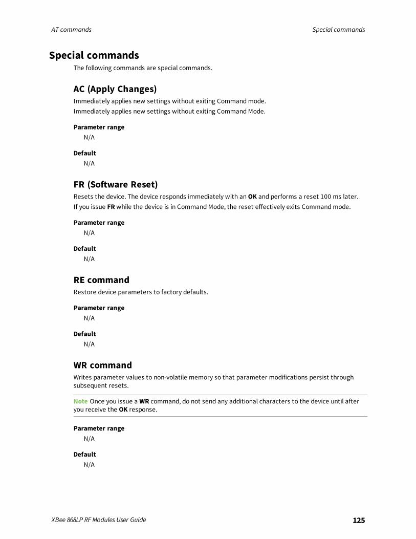
AT commands Special commands
XBee 868LP RF Modules User Guide 125
Special commandsThe following commands are special commands.
AC (Apply Changes)Immediately applies new settings without exiting Commandmode.Immediately applies new settings without exiting Command Mode.
Parameter rangeN/A
DefaultN/A
FR (Software Reset)Resets the device. The device responds immediately with anOK and performs a reset 100 ms later.If you issue FRwhile the device is in Command Mode, the reset effectively exits Commandmode.
Parameter rangeN/A
DefaultN/A
RE commandRestore device parameters to factory defaults.
Parameter rangeN/A
DefaultN/A
WR commandWrites parameter values to non-volatile memory so that parameter modifications persist throughsubsequent resets.
Note Once you issue a WR command, do not send any additional characters to the device until afteryou receive the OK response.
Parameter rangeN/A
DefaultN/A

AT commands MAC/PHY commands
XBee 868LP RF Modules User Guide 126
MAC/PHY commandsThe following AT commands are MAC/PHY commands.
CM (Channel Mask)CM allows you to selectively enable or disable channels used for RF communication. This is useful toavoid using frequencies that experience unacceptable levels of RF interference, or to operate twonetworks of radios on separate frequencies.This mask limits the channels where the device transmits. See Technical specifications for the list offrequencies. Channel 0 is bit 0. You must enable at least two channels, except when using only a singlefrequency of 869.85 MHz. When you use this mode (use 0x20000000), LBT+AFA is disabled and requiresthe power level to be 5 mW e.r.p. or less.This command is a bitfield.The CM command does not limit receive channels. If two devices have mutually exclusive values forCM (for example 0x0000FF00 and 0x000000FF), then communication is possible because both devicesstill listen on all possible channels, while limiting the transmission channels to those specified in theCM command.
Parameter range0 - 0x3FFFFFFF [bitfield]
DefaultEurope: 0x3FFFFFFF (channels 0 - 29, 863.15 - 869.85 MHz)Europe (single frequency mode): 0x20000000 (channel 29, 869.85 MHz)
HP (Preamble ID)The preamble ID for which the device communicates. Only devices with matching preamble IDs cancommunicate with each other. Different preamble IDs minimize interference between multiple sets ofdevices operating in the same vicinity. When receiving a packet, the device checks this before thenetwork ID, as it is encoded in the preamble, and the network ID is encoded in the MAC header.
Parameter range0 - 9
Default0
ID (Network ID)Set or read the user network identifier.Devices must have the same network identifier to communicate with each other.When receiving a packet, the device check this after the preamble ID. If you are using Originalequipment manufacturer (OEM) network IDs, 0xFFFF uses the factory value.
Parameter range0 - 0x7FFF
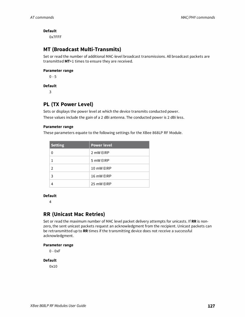
AT commands MAC/PHY commands
XBee 868LP RF Modules User Guide 127
Default0x7FFF
MT (Broadcast Multi-Transmits)Set or read the number of additional MAC-level broadcast transmissions. All broadcast packets aretransmittedMT+1 times to ensure they are received.
Parameter range0 - 5
Default3
PL (TX Power Level)Sets or displays the power level at which the device transmits conducted power.These values include the gain of a 2 dBi antenna. The conducted power is 2 dBi less.
Parameter rangeThese parameters equate to the following settings for the XBee 868LP RF Module.
Setting Power level
0 2 mW EIRP
1 5 mW EIRP
2 10 mW EIRP
3 16 mW EIRP
4 25 mW EIRP
Default4
RR (Unicast Mac Retries)Set or read the maximum number of MAC level packet delivery attempts for unicasts. If RR is non-zero, the sent unicast packets request an acknowledgment from the recipient. Unicast packets canbe retransmitted up to RR times if the transmitting device does not receive a successfulacknowledgment.
Parameter range0 - 0xF
Default0x10

AT commands Diagnostic commands
XBee 868LP RF Modules User Guide 128
ED (Energy Detect)Starts an energy detect scan. This command accepts an argument to specify the time in millisecondsto scan all channels. The device loops through all the available channels until the time elapses. Itreturns the maximal energy on each channel, a comma follows each value, and the list ends with acarriage return. The values returned reflect the energy level that ED detects in -dBm units.
Parameter range0 - 0xFF
Default0x10
Diagnostic commandsThe following AT commands are diagnostic commands. Diagnostic commands are typically volatile andwill not persist across a power cycle.
BC (Bytes Transmitted)The number of RF bytes transmitted. The firmware counts every byte of every packet, includingMAC/PHY headers and trailers. The purpose of this count is to estimate battery life by tracking timespent performing transmissions.This number rolls over to 0 from 0xFFFF.You can reset the counter to any unsigned 16-bit value by appending a hexadecimal parameter to thecommand.
Parameter range0 - 0xFFFF
Default0
DB (Last Packet RSSI)Reports the RSSI in -dBm of the last received RF data packet. DB returns a hexadecimal value for the -dBmmeasurement.For example, if DB returns 0x60, then the RSSI of the last packet received was -96 dBm.The XBee 868LP RF Module reports RSSI values within approximately 15 dBm of the sensitivity level ofthe device.Signals which exceed approximately -85 dBm are reported as approximately -85 dBm.DB only indicates the signal strength of the last hop. It does not provide an accurate qualitymeasurement for a multihop link.
Parameter range0 - 0xFF [read-only]
Default0
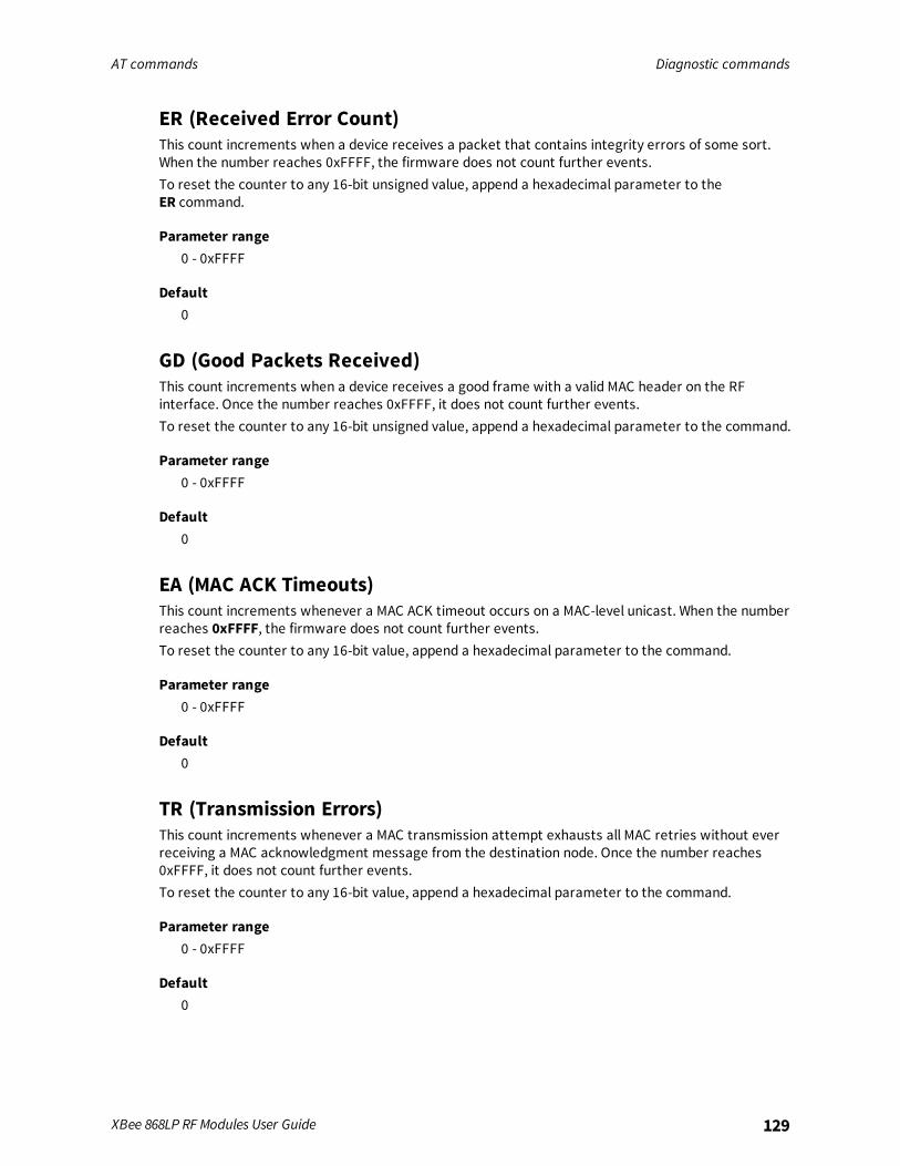
AT commands Diagnostic commands
XBee 868LP RF Modules User Guide 129
ER (Received Error Count)This count increments when a device receives a packet that contains integrity errors of some sort.When the number reaches 0xFFFF, the firmware does not count further events.To reset the counter to any 16-bit unsigned value, append a hexadecimal parameter to theER command.
Parameter range0 - 0xFFFF
Default0
GD (Good Packets Received)This count increments when a device receives a good frame with a valid MAC header on the RFinterface. Once the number reaches 0xFFFF, it does not count further events.To reset the counter to any 16-bit unsigned value, append a hexadecimal parameter to the command.
Parameter range0 - 0xFFFF
Default0
EA (MAC ACK Timeouts)This count increments whenever a MAC ACK timeout occurs on a MAC-level unicast. When the numberreaches 0xFFFF, the firmware does not count further events.To reset the counter to any 16-bit value, append a hexadecimal parameter to the command.
Parameter range0 - 0xFFFF
Default0
TR (Transmission Errors)This count increments whenever a MAC transmission attempt exhausts all MAC retries without everreceiving a MAC acknowledgment message from the destination node. Once the number reaches0xFFFF, it does not count further events.To reset the counter to any 16-bit value, append a hexadecimal parameter to the command.
Parameter range0 - 0xFFFF
Default0

AT commands Network commands
XBee 868LP RF Modules User Guide 130
UA (MAC Unicast Transmission Count)This count increments whenever a MAC unicast transmission occurs that requests an ACK. Once thenumber reaches 0xFFFF, it does not count further events.You can reset the counter to any 16-bit unsigned value by appending a hexadecimal parameter to thecommand.
Parameter range0 - 0xFFFF
Default0
%H (MAC Unicast One Hop Time)The MAC unicast one hop time timeout in milliseconds. If you change the MAC parameters it canchange this value.
Parameter range[read-only]
Default0xCF
%8 (MAC Broadcast One Hop Time)The MAC broadcast one hop time timeout in milliseconds. If you change MAC parameters, it canchange this value.
Parameter range[read-only]
Default0x1BE
Network commandsThe following commands are network commands.
CE (Node Messaging Options)The routing andmessaging mode bit field of the device.A routing device repeats broadcasts. Indirect Messaging Coordinators do not transmit point-to-multipoint unicasts until an end device requests them. Setting a device as an end device causes it toregularly send polls to its Indirect Messaging Coordinator. Nodes can also be configured to route, ornot route, multi-hop packets.

AT commands Network commands
XBee 868LP RF Modules User Guide 131
Bit Description
Bit 0 Indirect Messaging Coordinator enable. All point-to-multipoint unicasts will be helduntil requested by a polling end device.
Bit 1 Disable routing on this node. When set, this node will not propagate broadcasts orbecome an intermediate node in a DigiMesh route. This node will not function as arepeater.
Bit 2 Indirect Messaging Polling enable. Periodically send requests for messages held by thenode’s coordinator.
Note Bit 0 and Bit 2 cannot be set at the same time.
Parameter range0 - 6
Default0
BH commandThe number of hops for broadcast data transmissions.Set the value to 0 for the maximum number of hops.If you set BH greater than NH, the device uses the value of NH.
Parameter range0 - 0x20
Default0
NH (Network Hops)The maximum number of hops expected to be seen in a network route. This value does not limit thenumber of hops allowed, but it is used to calculate timeouts waiting for network acknowledgments.Both variants are supported.
Parameter range1 - 0x20
Default7
NN (Network Delay Slots)Set or read the maximum random number of network delay slots before rebroadcasting a networkpacket.
Parameter range1 - 5
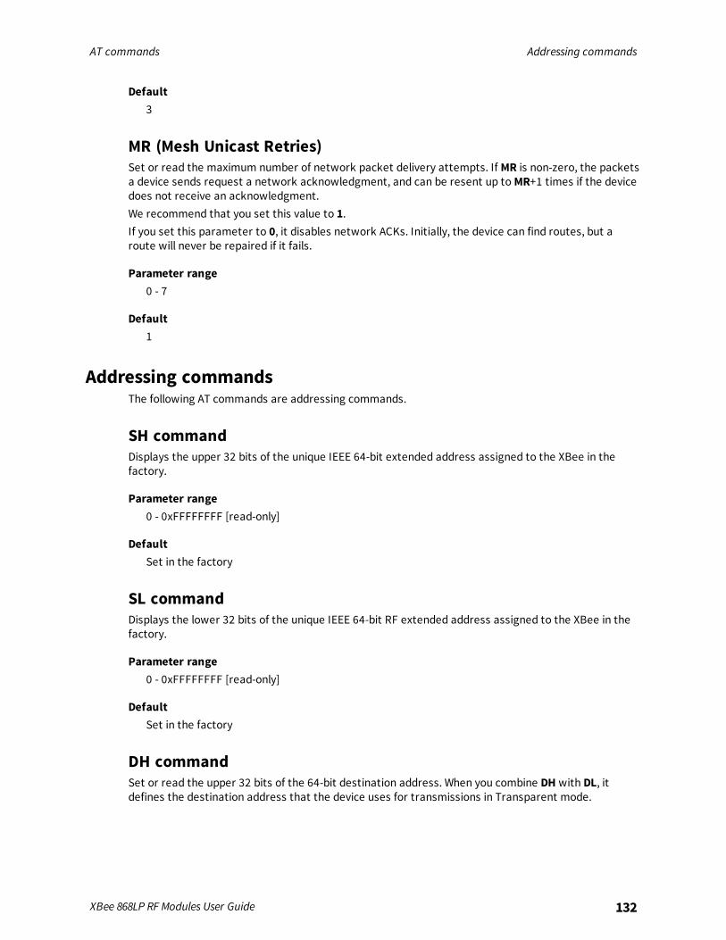
AT commands Addressing commands
XBee 868LP RF Modules User Guide 132
Default3
MR (Mesh Unicast Retries)Set or read the maximum number of network packet delivery attempts. If MR is non-zero, the packetsa device sends request a network acknowledgment, and can be resent up toMR+1 times if the devicedoes not receive an acknowledgment.We recommend that you set this value to 1.If you set this parameter to 0, it disables network ACKs. Initially, the device can find routes, but aroute will never be repaired if it fails.
Parameter range0 - 7
Default1
Addressing commandsThe following AT commands are addressing commands.
SH commandDisplays the upper 32 bits of the unique IEEE 64-bit extended address assigned to the XBee in thefactory.
Parameter range0 - 0xFFFFFFFF [read-only]
DefaultSet in the factory
SL commandDisplays the lower 32 bits of the unique IEEE 64-bit RF extended address assigned to the XBee in thefactory.
Parameter range0 - 0xFFFFFFFF [read-only]
DefaultSet in the factory
DH commandSet or read the upper 32 bits of the 64-bit destination address. When you combine DH with DL, itdefines the destination address that the device uses for transmissions in Transparent mode.
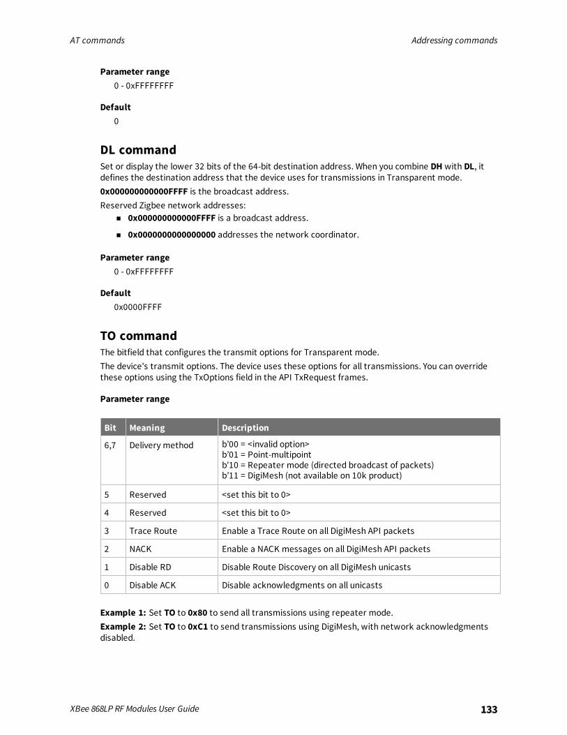
AT commands Addressing commands
XBee 868LP RF Modules User Guide 133
Parameter range0 - 0xFFFFFFFF
Default0
DL commandSet or display the lower 32 bits of the 64-bit destination address. When you combine DH with DL, itdefines the destination address that the device uses for transmissions in Transparent mode.0x000000000000FFFF is the broadcast address.Reserved Zigbee network addresses:
n 0x000000000000FFFF is a broadcast address.
n 0x0000000000000000 addresses the network coordinator.
Parameter range0 - 0xFFFFFFFF
Default0x0000FFFF
TO commandThe bitfield that configures the transmit options for Transparent mode.The device's transmit options. The device uses these options for all transmissions. You can overridethese options using the TxOptions field in the API TxRequest frames.
Parameter range
Bit Meaning Description
6,7 Delivery method b’00 = <invalid option>b’01 = Point-multipointb'10 = Repeater mode (directed broadcast of packets)b’11 = DigiMesh (not available on 10k product)
5 Reserved <set this bit to 0>
4 Reserved <set this bit to 0>
3 Trace Route Enable a Trace Route on all DigiMesh API packets
2 NACK Enable a NACK messages on all DigiMesh API packets
1 Disable RD Disable Route Discovery on all DigiMesh unicasts
0 Disable ACK Disable acknowledgments on all unicasts
Example 1: Set TO to 0x80 to send all transmissions using repeater mode.Example 2: Set TO to 0xC1 to send transmissions using DigiMesh, with network acknowledgmentsdisabled.
AT commands Addressing commands
XBee 868LP RF Modules User Guide 134
n Bits 6 and 7 cannot be set to DigiMesh on the 10k build.
n Bits 4 and 5 must be set to 0.
n Bits 1, 2, and 3 cannot be set on the 10k build.
When you set BR to 0 the TO option has the DigiMesh and Repeater mode disabled automatically.
Default0x40 (10k product)0xC0 (80k product)
NI commandStores the node identifier string for a device, which is a user-defined name or description of thedevice. This can be up to 20 ASCII characters.
n The command automatically ends when the maximum bytes for the string have been entered.
Use the ND (Network Discovery) command with this string as an argument to easily identify deviceson the network.The DN command also uses this identifier.
Parameter rangeA string of case-sensitive ASCII printable characters from 0 to 20 bytes in length. A carriage returnor a comma automatically ends the command.
DefaultOne ASCII space character (0x20)
NT (Node Discover Timeout)Sets the amount of time a base node waits for responses from other nodes when using the ND (NodeDiscover) or DN (Discover Node) commands. The value randomizes the responses to alleviate networkcongestion.
Parameter range0x20 - 0x2EE0 (x 100 ms)
Default0x82 (13 seconds)
NO (Node Discovery Options)Set or read the network discovery options value for the ND (Network Discovery) command on aparticular device. The options bit field value changes the behavior of the ND command and whatoptional values the local device returns when it receives an ND command or API Node IdentificationIndicator (0x95) frame.
Parameter range0x0 - 0x7 (bit field)
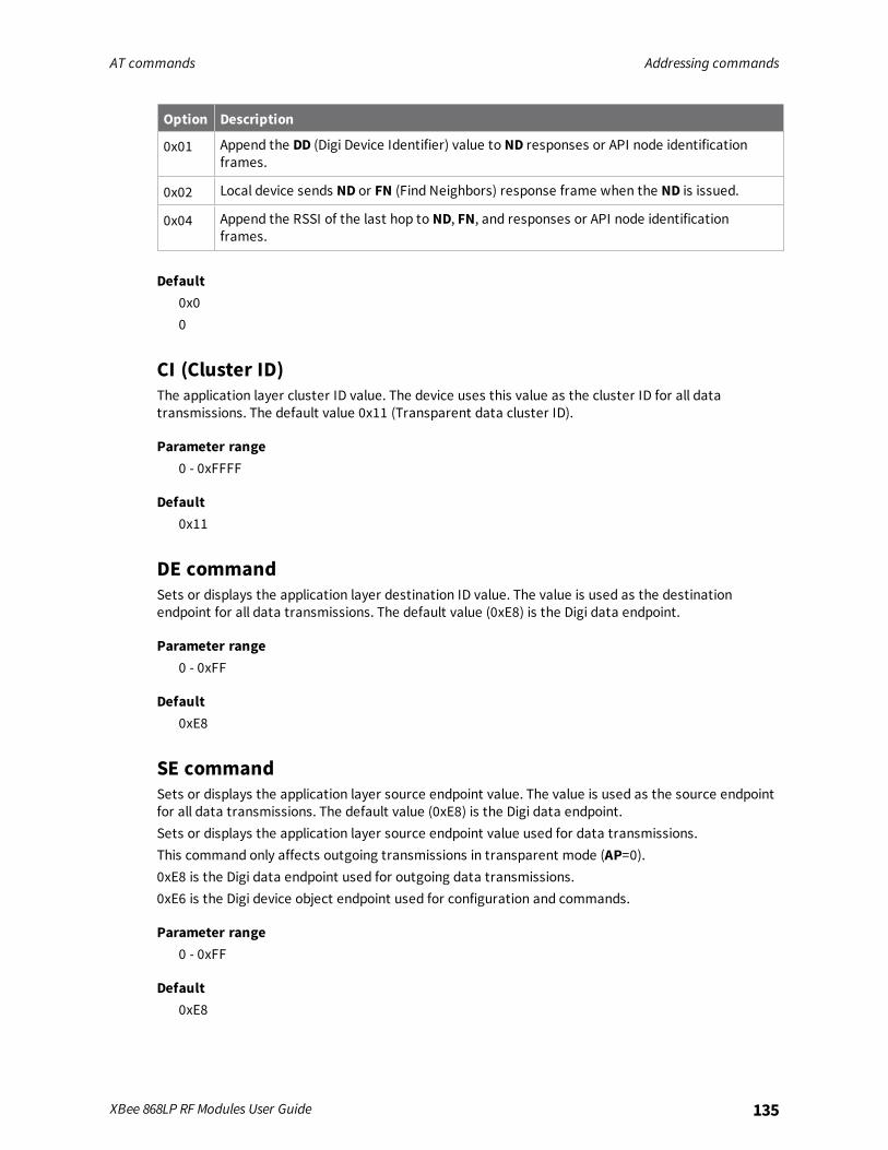
AT commands Addressing commands
XBee 868LP RF Modules User Guide 135
Option Description
0x01 Append the DD (Digi Device Identifier) value to ND responses or API node identificationframes.
0x02 Local device sends ND or FN (Find Neighbors) response frame when the ND is issued.
0x04 Append the RSSI of the last hop to ND, FN, and responses or API node identificationframes.
Default0x00
CI (Cluster ID)The application layer cluster ID value. The device uses this value as the cluster ID for all datatransmissions. The default value 0x11 (Transparent data cluster ID).
Parameter range0 - 0xFFFF
Default0x11
DE commandSets or displays the application layer destination ID value. The value is used as the destinationendpoint for all data transmissions. The default value (0xE8) is the Digi data endpoint.
Parameter range0 - 0xFF
Default0xE8
SE commandSets or displays the application layer source endpoint value. The value is used as the source endpointfor all data transmissions. The default value (0xE8) is the Digi data endpoint.Sets or displays the application layer source endpoint value used for data transmissions.This command only affects outgoing transmissions in transparent mode (AP=0).0xE8 is the Digi data endpoint used for outgoing data transmissions.0xE6 is the Digi device object endpoint used for configuration and commands.
Parameter range0 - 0xFF
Default0xE8

AT commands Addressing discovery/configuration commands
XBee 868LP RF Modules User Guide 136
Addressing discovery/configuration commands
AG (Aggregator Support)The AG command sends a broadcast through the network that has the following effects on nodes thatreceive the broadcast:
n The receiving node establishes a DigiMesh route back to the originating node, if there is spacein the routing table.
n The DH and DL of the receiving node update to the address of the originating node if the AGparameter matches the current DH/DL of the receiving node.
n API-enabled devices with updated DH and DL send an Aggregate Addressing Update frame(0x8E) out the serial port.
Parameter rangeAny 64-bit address
DefaultN/A
DN (Discover Node)Resolves an NI (Node identifier) string to a physical address (case sensitive).The following events occur after DN discovers the destination node:When DN is sent in Commandmode:
1. The device sets DL and DH to the extended (64-bit) address of the device with the matching NIstring.
2. The receiving device returns OK (or ERROR).
3. The device exits Commandmode to allow for immediate communication. If an ERROR isreceived, the device does not exit Commandmode.
When DN is sent as an API frame, the receiving device returns 0xFFFE followed by its 64-bit extendedaddresses in an API Command Response frame.
Parameter range20-byte ASCII string
DefaultN/A
ND (Network Discover)Discovers and reports all of the devices it finds on a network. The command reports the followinginformation after a jittered time delay (.
MY<CR>SH<CR>SL<CR>DB<CR> (Contains the detected signal strength of the response in negative dBm units)

AT commands Diagnostic - addressing commands
XBee 868LP RF Modules User Guide 137
NI<CR> (Variable length)<CR>
After (NT * 100) milliseconds, the command ends by returning a <CR>. ND also accepts a NI (NodeIdentifier) as a parameter (optional). In this case, only a device that matches the supplied identifierresponds.If you send ND through a local API frame, the device returns each response as a separate AT_CMD_Response packet. The data consists of the above listed bytes without the carriage return delimiters.The NI string end in a “0x00” null character.
Parameter rangeN/A
DefaultN/A
FN (Find Neighbors)Discovers and reports all devices found within immediate (1 hop) RF range. FN reports the followinginformation for each device it discovers:
MY<CR> (always 0xFFFE)SH<CR>SL<CR>NI<CR> (Variable length)PARENT_NETWORK ADDRESS<CR> (2 Bytes) (always 0xFFFE)DEVICE_TYPE<CR> (1 Byte: 0 = Coordinator, 1 = Router, 2 = End Device)STATUS<CR> (1 Byte: Reserved)PROFILE_ID<CR> (2 Bytes)MANUFACTURER_ID<CR> (2 Bytes)DIGI DEVICE TYPE<CR> (4 Bytes. Optionally included based on NO settings.)RSSI OF LAST HOP<CR> (1 Byte. Optionally included based on NO settings.)<CR>
If you send the FN command in Commandmode, after (NT*100) ms + overhead time, the commandends by returning a carriage return, represented by <CR>.If you send the FN command through a local API frame, each response returns as a separate Local orRemote AT Command Response API packet, respectively. The data consists of the bytes in theprevious list without the carriage return delimiters. The NI string ends in a 0x00 null character.
Parameter rangeN/A
DefaultN/A
Diagnostic - addressing commandsThe following AT command is a Diagnostic - addressing command.
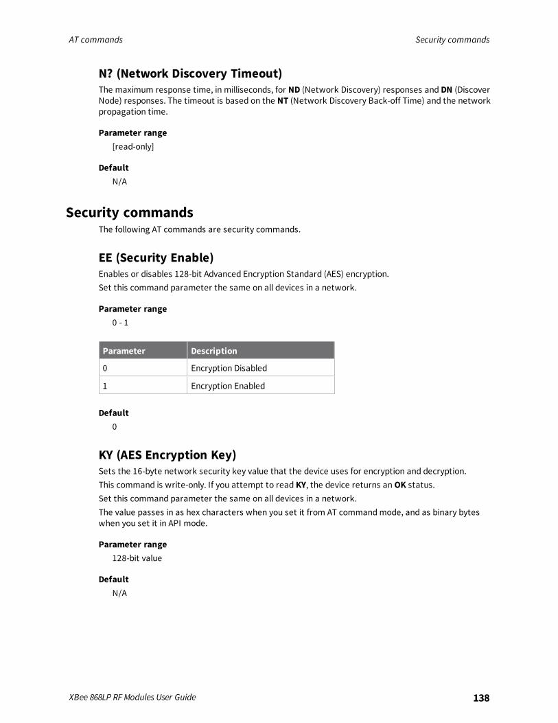
AT commands Security commands
XBee 868LP RF Modules User Guide 138
N? (Network Discovery Timeout)The maximum response time, in milliseconds, for ND (Network Discovery) responses and DN (DiscoverNode) responses. The timeout is based on the NT (Network Discovery Back-off Time) and the networkpropagation time.
Parameter range[read-only]
DefaultN/A
Security commandsThe following AT commands are security commands.
EE (Security Enable)Enables or disables 128-bit Advanced Encryption Standard (AES) encryption.Set this command parameter the same on all devices in a network.
Parameter range0 - 1
Parameter Description
0 Encryption Disabled
1 Encryption Enabled
Default0
KY (AES Encryption Key)Sets the 16-byte network security key value that the device uses for encryption and decryption.This command is write-only. If you attempt to read KY, the device returns anOK status.Set this command parameter the same on all devices in a network.The value passes in as hex characters when you set it from AT commandmode, and as binary byteswhen you set it in API mode.
Parameter range128-bit value
DefaultN/A

AT commands Serial interfacing commands
XBee 868LP RF Modules User Guide 139
Serial interfacing commands
BD (Baud Rate)Sets or displays the serial interface baud rate for communication between the device's serial port andthe host.Values from 0 - 8 select preset standard rates.Values at 0x100 and above select the actual baud rate if the host supports it.
Parameter rangeStandard baud rates: 0x0 - 0x8Non-standard baud rates: 0x100 to 0x6ACFC0
Parameter Description
0x0 1200 b/s
0x1 2400 b/s
0x2 4800 b/s
0x3 9600 b/s
0x4 19200 b/s
0x5 38400 b/s
0x6 57600 b/s
0x7 115200 b/s
0x8 230400 b/s
The baud rate limit is 7 Mb/s.
Default0x03 (9600 b/s)
NB (Parity)Set or read the serial parity settings for UART communications.
Parameter range0x00 - 0x02
Parameter Description
0x00 No parity
0x01 Even parity
0x02 Odd parity
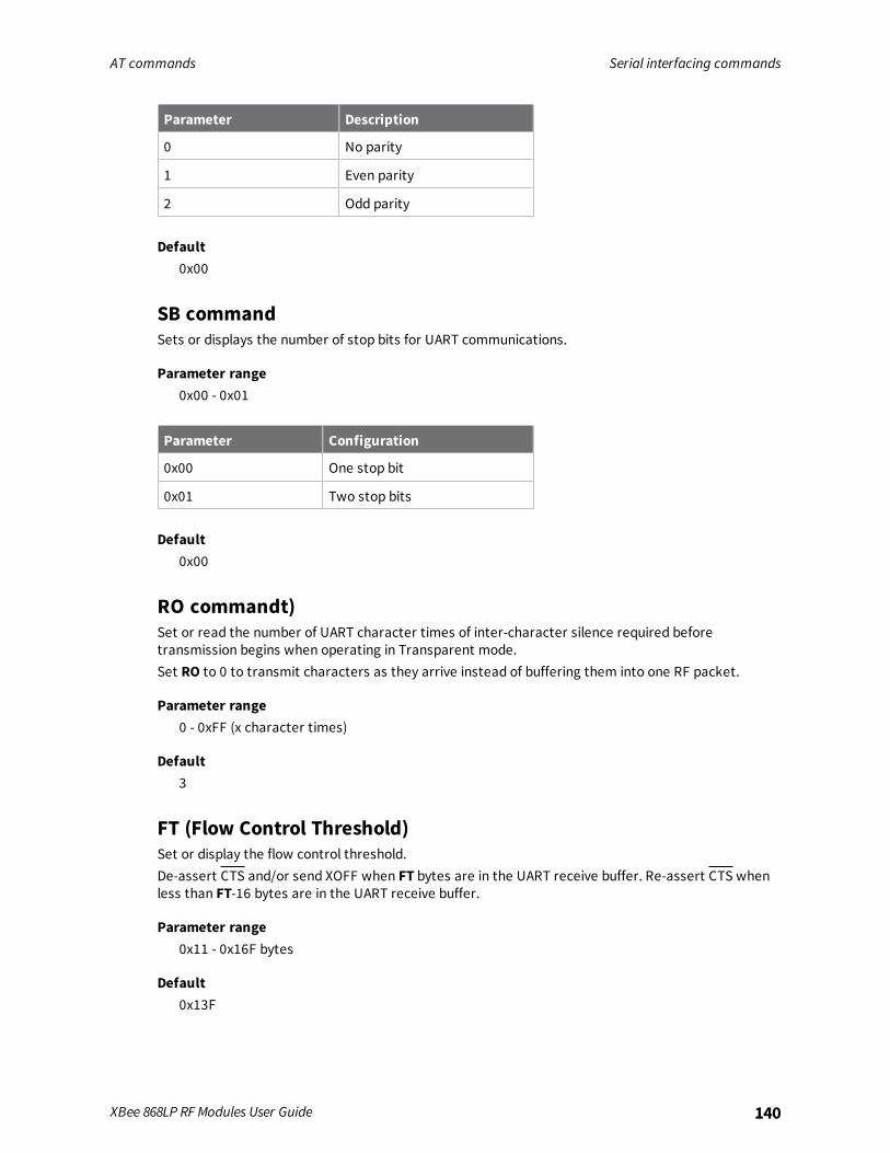
AT commands Serial interfacing commands
XBee 868LP RF Modules User Guide 140
Parameter Description
0 No parity
1 Even parity
2 Odd parity
Default0x00
SB commandSets or displays the number of stop bits for UART communications.
Parameter range0x00 - 0x01
Parameter Configuration
0x00 One stop bit
0x01 Two stop bits
Default0x00
RO commandt)Set or read the number of UART character times of inter-character silence required beforetransmission begins when operating in Transparent mode.Set RO to 0 to transmit characters as they arrive instead of buffering them into one RF packet.
Parameter range0 - 0xFF (x character times)
Default3
FT (Flow Control Threshold)Set or display the flow control threshold.De-assert CTS and/or send XOFF when FT bytes are in the UART receive buffer. Re-assert CTS whenless than FT-16 bytes are in the UART receive buffer.
Parameter range0x11 - 0x16F bytes
Default0x13F

AT commands I/O settings commands
XBee 868LP RF Modules User Guide 141
API ModeSets or reads the UART API mode.
Parameter range0 - 2The following settings are allowed:
Parameter Description
0 Transparent mode, API mode is off. All UART input and output is raw data and thedevice uses the RO parameter to delineate packets.
1 API Mode Without Escapes. The device packetizes all UART input and output data in APIformat, without escape sequences.
2 API Mode With Escapes. The device is in API mode and inserts escaped sequences toallow for control characters. The device passes XON, XOFF, Escape, and the 0x7Edelimiter as data.
Default0
AO commandThe API data frame output format for RF packets received. This parameter applies to both theUART and SPI interfaces.
Parameter range0, 1
Parameter Description
0 API Rx Indicator - 0x90, this is for standard data frames.
1 API Explicit Rx Indicator - 0x91, this is for Explicit Addressing data frames.
Default0
I/O settings commandsThe following AT commands are I/O settings commands.
CB commandUse CB to simulate commissioning pushbutton presses in software.Set the parameter value to the number of button presses that you want to simulate. For example,send CB1 to perform the action of pressing the Commissioning Pushbutton once.See The Commissioning Pushbutton.See Commissioning pushbutton
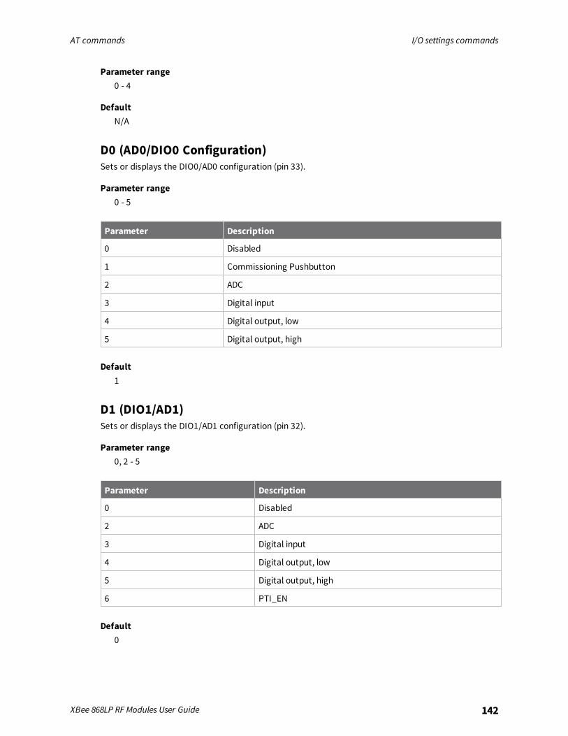
AT commands I/O settings commands
XBee 868LP RF Modules User Guide 142
Parameter range0 - 4
DefaultN/A
D0 (AD0/DIO0 Configuration)Sets or displays the DIO0/AD0 configuration (pin 33).
Parameter range0 - 5
Parameter Description
0 Disabled
1 Commissioning Pushbutton
2 ADC
3 Digital input
4 Digital output, low
5 Digital output, high
Default1
D1 (DIO1/AD1)Sets or displays the DIO1/AD1 configuration (pin 32).
Parameter range0, 2 - 5
Parameter Description
0 Disabled
2 ADC
3 Digital input
4 Digital output, low
5 Digital output, high
6 PTI_EN
Default0
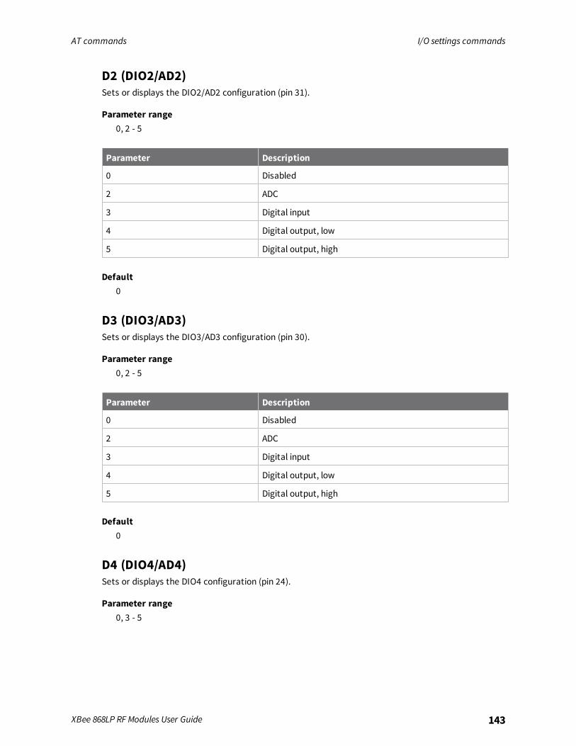
AT commands I/O settings commands
XBee 868LP RF Modules User Guide 143
D2 (DIO2/AD2)Sets or displays the DIO2/AD2 configuration (pin 31).
Parameter range0, 2 - 5
Parameter Description
0 Disabled
2 ADC
3 Digital input
4 Digital output, low
5 Digital output, high
Default0
D3 (DIO3/AD3)Sets or displays the DIO3/AD3 configuration (pin 30).
Parameter range0, 2 - 5
Parameter Description
0 Disabled
2 ADC
3 Digital input
4 Digital output, low
5 Digital output, high
Default0
D4 (DIO4/AD4)Sets or displays the DIO4 configuration (pin 24).
Parameter range0, 3 - 5
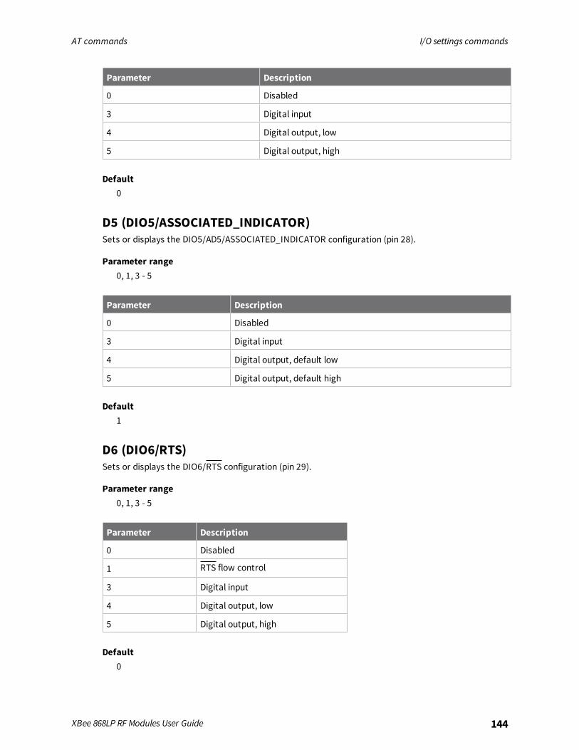
AT commands I/O settings commands
XBee 868LP RF Modules User Guide 144
Parameter Description
0 Disabled
3 Digital input
4 Digital output, low
5 Digital output, high
Default0
D5 (DIO5/ASSOCIATED_INDICATOR)Sets or displays the DIO5/AD5/ASSOCIATED_INDICATOR configuration (pin 28).
Parameter range0, 1, 3 - 5
Parameter Description
0 Disabled
3 Digital input
4 Digital output, default low
5 Digital output, default high
Default1
D6 (DIO6/RTS)Sets or displays the DIO6/RTS configuration (pin 29).
Parameter range0, 1, 3 - 5
Parameter Description
0 Disabled
1 RTS flow control
3 Digital input
4 Digital output, low
5 Digital output, high
Default0

AT commands I/O settings commands
XBee 868LP RF Modules User Guide 145
D7 (DIO7/CTS)Sets or displays the DIO7/CTS configuration (pin 25).
Parameter range0, 1, 3 - 7
Parameter Description
0 Disabled
1 CTS flow control
3 Digital input
4 Digital output, low
5 Digital output, high
6 RS-485 Tx enable, low Tx (0 V on transmit, high when idle)
7 RS-485 Tx enable high, high Tx (high on transmit, 0 V when idle)
Default0x1
D8 (DIO8/SLEEP_REQUEST)Sets or displays the DIO8/SLEEP_REQUEST configuration (pin 10).
Parameter range0, 1, 3 - 5
Parameter Description
0 Disabled
1 Sleep request
2 N/A
3 Digital input
4 Digital output, low
5 Digital output, high
Default1
D9 (DIO9/ON_SLEEP)Sets or displays the DIO9/ON_SLEEP configuration (pin 26).

AT commands I/O settings commands
XBee 868LP RF Modules User Guide 146
Parameter range0, 1, 3 - 5
Parameter Description
0 Disabled
1 ON/SLEEP output
3 Digital input
4 Digital output, low
5 Digital output, high
Default1
P0 (DIO10/RSSI/PWM0 Configuration)Sets or displays the PWM0/RSSI/DIO10 configuration (pin 7).Sets or displays the DIO10/RSSI configuration.
Parameter range0 - 5
Parameter Description
0 Disabled
1 RSSI PWM0 output
2 PWM0 output
3 Digital input
4 Digital output, low
5 Digital output, high
Default1
P1 (DIO11/PWM1 Configuration)Sets or displays the DIO11/PWM1 configuration (pin 8).
Parameter range0 - 5
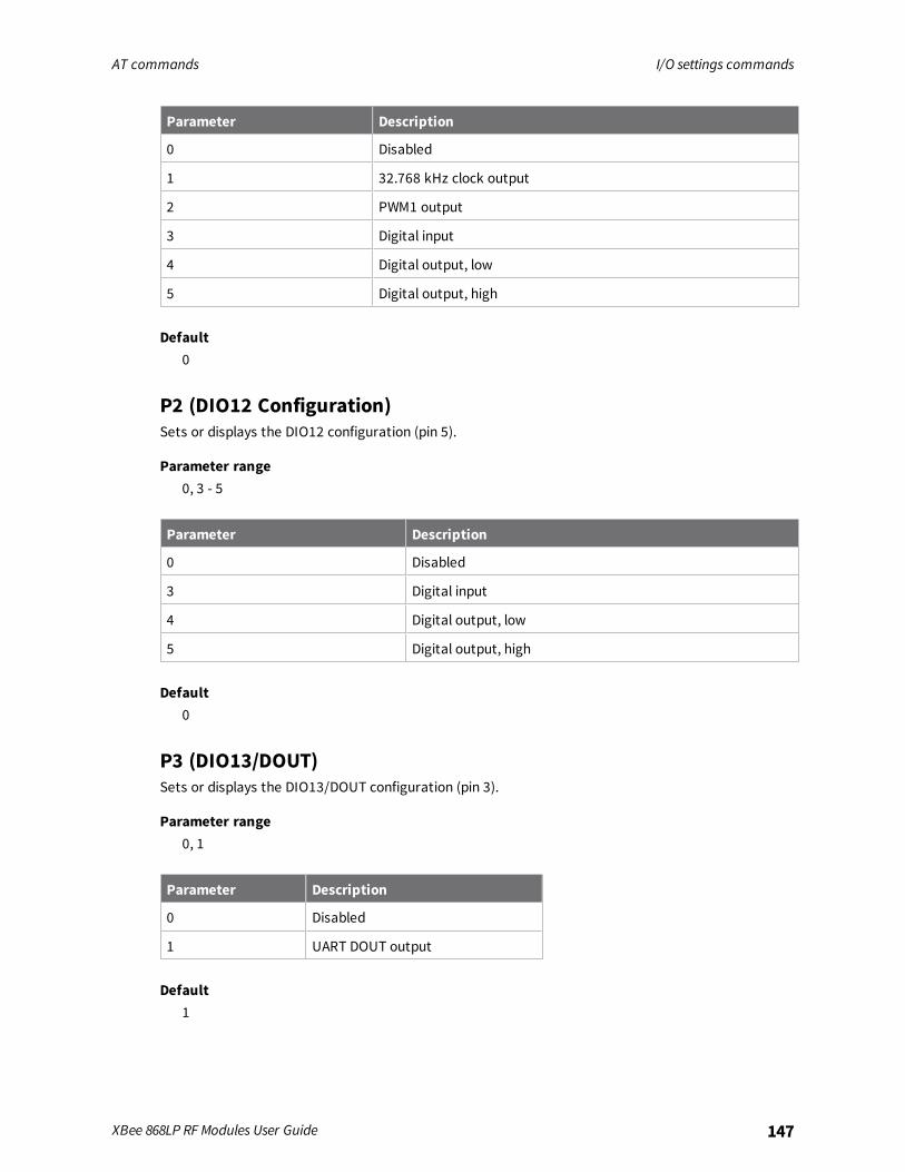
AT commands I/O settings commands
XBee 868LP RF Modules User Guide 147
Parameter Description
0 Disabled
1 32.768 kHz clock output
2 PWM1 output
3 Digital input
4 Digital output, low
5 Digital output, high
Default0
P2 (DIO12 Configuration)Sets or displays the DIO12 configuration (pin 5).
Parameter range0, 3 - 5
Parameter Description
0 Disabled
3 Digital input
4 Digital output, low
5 Digital output, high
Default0
P3 (DIO13/DOUT)Sets or displays the DIO13/DOUT configuration (pin 3).
Parameter range0, 1
Parameter Description
0 Disabled
1 UART DOUT output
Default1
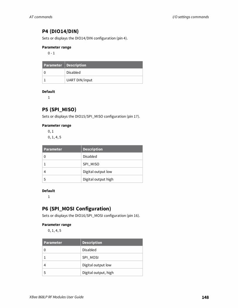
AT commands I/O settings commands
XBee 868LP RF Modules User Guide 148
P4 (DIO14/DIN)Sets or displays the DIO14/DIN configuration (pin 4).
Parameter range0 - 1
Parameter Description
0 Disabled
1 UART DIN/input
Default1
P5 (SPI_MISO)Sets or displays the DIO15/SPI_MISO configuration (pin 17).
Parameter range0, 10, 1, 4, 5
Parameter Description
0 Disabled
1 SPI_MISO
4 Digital output low
5 Digital output high
Default1
P6 (SPI_MOSI Configuration)Sets or displays the DIO16/SPI_MOSI configuration (pin 16).
Parameter range0, 1, 4, 5
Parameter Description
0 Disabled
1 SPI_MOSI
4 Digital output low
5 Digital output, high

AT commands I/O settings commands
XBee 868LP RF Modules User Guide 149
Default1
P7 (DIO17/SPI_SSEL )Sets or displays the DIO17/SPI_SSEL configuration (pin 15).
Parameter range0, 1, 4, 5
Parameter Description
0 Disabled
1 SPI_SSEL
4 Digital output low
5 Digital output, high
Default1
P8 (DIO18/SPI_SCLK)Sets or displays the DIO18/SPI_SCLK configuration (pin 14).
Parameter range0, 1, 4, 5
Parameter Description
0 Disabled
1 SPI_SCLK
4 Digital output low
5 Digital output high
Default1
P9 (SPI_ATTN)Sets or displays the DIO19/SPI_ATTN configuration (pin 12).
Parameter range0, 1, 4 - 6
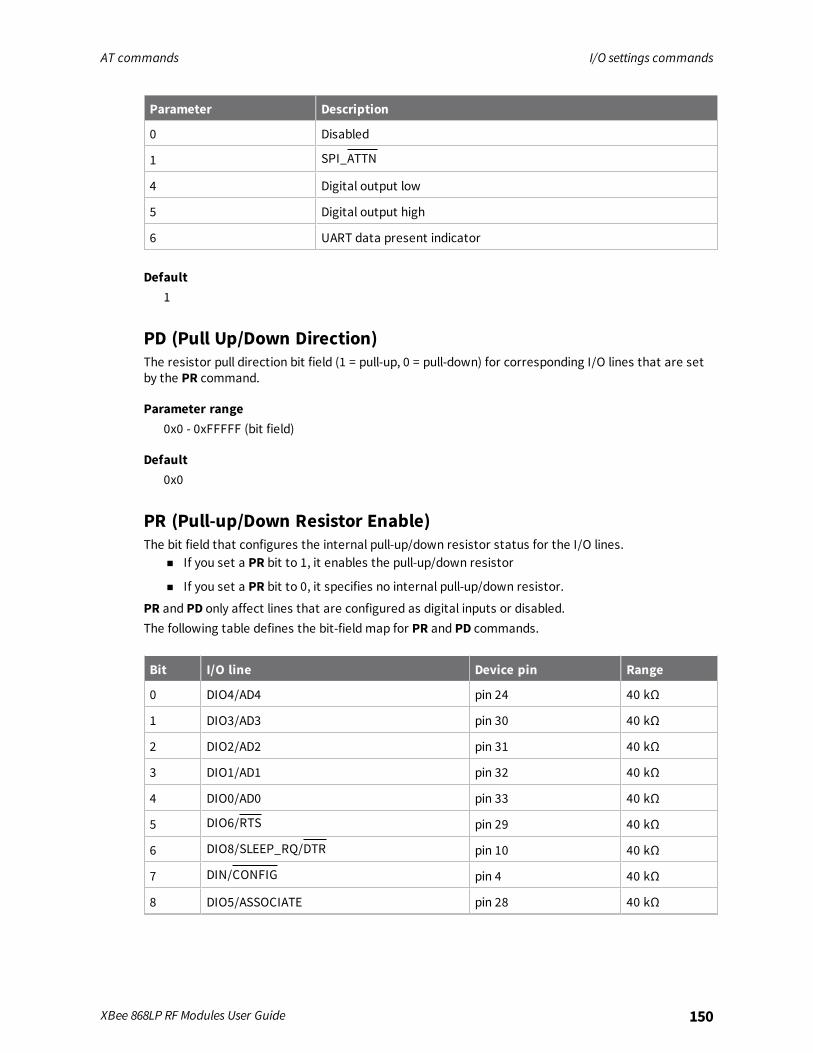
AT commands I/O settings commands
XBee 868LP RF Modules User Guide 150
Parameter Description
0 Disabled
1 SPI_ATTN
4 Digital output low
5 Digital output high
6 UART data present indicator
Default1
PD (Pull Up/Down Direction)The resistor pull direction bit field (1 = pull-up, 0 = pull-down) for corresponding I/O lines that are setby the PR command.
Parameter range0x0 - 0xFFFFF (bit field)
Default0x0
PR (Pull-up/Down Resistor Enable)The bit field that configures the internal pull-up/down resistor status for the I/O lines.
n If you set a PR bit to 1, it enables the pull-up/down resistor
n If you set a PR bit to 0, it specifies no internal pull-up/down resistor.
PR and PD only affect lines that are configured as digital inputs or disabled.The following table defines the bit-field map for PR and PD commands.
Bit I/O line Device pin Range
0 DIO4/AD4 pin 24 40 kΩ
1 DIO3/AD3 pin 30 40 kΩ
2 DIO2/AD2 pin 31 40 kΩ
3 DIO1/AD1 pin 32 40 kΩ
4 DIO0/AD0 pin 33 40 kΩ
5 DIO6/RTS pin 29 40 kΩ
6 DIO8/SLEEP_RQ/DTR pin 10 40 kΩ
7 DIN/CONFIG pin 4 40 kΩ
8 DIO5/ASSOCIATE pin 28 40 kΩ
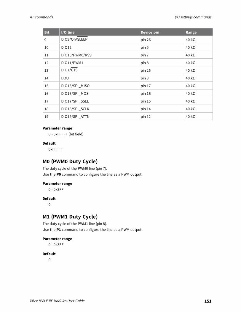
AT commands I/O settings commands
XBee 868LP RF Modules User Guide 151
Bit I/O line Device pin Range
9 DIO9/On/SLEEP pin 26 40 kΩ
10 DIO12 pin 5 40 kΩ
11 DIO10/PWM0/RSSI pin 7 40 kΩ
12 DIO11/PWM1 pin 8 40 kΩ
13 DIO7/CTS pin 25 40 kΩ
14 DOUT pin 3 40 kΩ
15 DIO15/SPI_MISO pin 17 40 kΩ
16 DIO16/SPI_MOSI pin 16 40 kΩ
17 DIO17/SPI_SSEL pin 15 40 kΩ
18 DIO18/SPI_SCLK pin 14 40 kΩ
19 DIO19/SPI_ATTN pin 12 40 kΩ
Parameter range0 - 0xFFFFF (bit field)
Default0xFFFFF
M0 (PWM0 Duty Cycle)The duty cycle of the PWM0 line (pin 7).Use the P0 command to configure the line as a PWM output.
Parameter range0 - 0x3FF
Default0
M1 (PWM1 Duty Cycle)The duty cycle of the PWM1 line (pin 8).Use the P1 command to configure the line as a PWM output.
Parameter range0 - 0x3FF
Default0
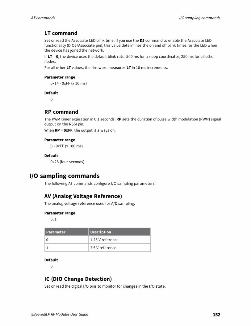
AT commands I/O sampling commands
XBee 868LP RF Modules User Guide 152
LT commandSet or read the Associate LED blink time. If you use the D5 command to enable the Associate LEDfunctionality (DIO5/Associate pin), this value determines the on and off blink times for the LED whenthe device has joined the network.If LT = 0, the device uses the default blink rate: 500 ms for a sleep coordinator, 250 ms for all othernodes.For all other LT values, the firmware measures LT in 10 ms increments.
Parameter range0x14 - 0xFF (x 10 ms)
Default0
RP commandThe PWM timer expiration in 0.1 seconds. RP sets the duration of pulse width modulation (PWM) signaloutput on the RSSI pin.When RP = 0xFF, the output is always on.
Parameter range0 - 0xFF (x 100 ms)
Default0x28 (four seconds)
I/O sampling commandsThe following AT commands configure I/O sampling parameters.
AV (Analog Voltage Reference)The analog voltage reference used for A/D sampling.
Parameter range0, 1
Parameter Description
0 1.25 V reference
1 2.5 V reference
Default0
IC (DIO Change Detection)Set or read the digital I/O pins to monitor for changes in the I/O state.
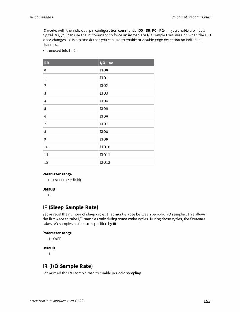
AT commands I/O sampling commands
XBee 868LP RF Modules User Guide 153
IC works with the individual pin configuration commands (D0 - D9, P0 - P2) . If you enable a pin as adigital I/O, you can use the IC command to force an immediate I/O sample transmission when the DIOstate changes. IC is a bitmask that you can use to enable or disable edge detection on individualchannels.Set unused bits to 0.
Bit I/O line
0 DIO0
1 DIO1
2 DIO2
3 DIO3
4 DIO4
5 DIO5
6 DIO6
7 DIO7
8 DIO8
9 DIO9
10 DIO10
11 DIO11
12 DIO12
Parameter range0 - 0xFFFF (bit field)
Default0
IF (Sleep Sample Rate)Set or read the number of sleep cycles that must elapse between periodic I/O samples. This allowsthe firmware to take I/O samples only during some wake cycles. During those cycles, the firmwaretakes I/O samples at the rate specified by IR.
Parameter range1 - 0xFF
Default1
IR (I/O Sample Rate)Set or read the I/O sample rate to enable periodic sampling.
AT commands Sleep commands
XBee 868LP RF Modules User Guide 154
If you set the I/O sample rate to greater than 0, the device samples and transmits all enabled digitalI/O and analog inputs every IRmilliseconds. I/O Samples transmit to the address specified by DT.To enable periodic sampling, set IR to a non-zero value, and enable the analog or digital I/Ofunctionality of at least one device pin. The sample rate is measured in milliseconds.
WARNING! If you set IR to 1 or 2, the device will not keep up andmany samples will belost.
Parameter range0 - 0xFFFF (x 1 ms)
Default0
TP (Temperature)The current module temperature in degrees Celsius in 8-bit two’s compliment format. For example0x1A = 26 °C, and 0xF6 = -10 °C.
Parameter range0 - 0xFF [read-only]
DefaultN/A
IS commandForces a read of all enabled digital and analog input lines.
Parameter rangeN/A
DefaultN/A
%V (Voltage Supply Monitoring)Displays the supply voltage of the device in mV units.
Parameter rangeThis is a read-only parameter
DefaultN/A
Sleep commandsThe following AT commands are sleep commands.

AT commands Sleep commands
XBee 868LP RF Modules User Guide 155
SM commandSets or displays the sleepmode of the device.
Parameter range0, 1, 4, 5, 7, 8
Parameter Description
0 Normal.
1 Pin sleep. In this mode, the sleep/wake state of the module is controlled by the SLEEP_REQUEST line.
4 Asynchronous Cyclic Sleep. In this mode, the device periodically sleeps and wakesbased on the SP and ST commands.
5 Asynchronous cyclic sleep with pin wake-up. In this mode, the device is similar toasynchronous cyclic sleep. The device terminates a sleep period when it detects afalling edge of the SLEEP_REQUEST line.
7 Sleep Support
8 Synchronized Cyclic Sleep
Default0
SO commandSet or read the sleep options bit field of a device. This command is a bitmask.You cannot set bit 0 and bit 1 at the same time.
Parameter range0 - 0x13E [bit field]For synchronous sleep devices, the following sleep bit field options are defined:
Bit Option
0 Preferred sleep coordinator; setting this bit causes a sleep compatible device to always act assleep coordinator
1 Non-sleep coordinator; setting this bit causes a device to never act as a sleep coordinator
2 Enable API sleep status messages
3 Disable early wake-up for missed syncs
4 Enable node type equality (disables seniority based on device type)
5 Disable lone coordinator sync repeat
For asynchronous sleep devices, the following sleep bit field options are defined:
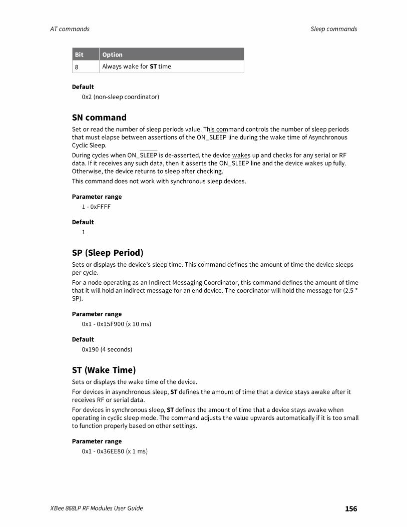
AT commands Sleep commands
XBee 868LP RF Modules User Guide 156
Bit Option
8 Always wake for ST time
Default0x2 (non-sleep coordinator)
SN commandSet or read the number of sleep periods value. This command controls the number of sleep periodsthat must elapse between assertions of the ON_SLEEP line during the wake time of AsynchronousCyclic Sleep.During cycles when ON_SLEEP is de-asserted, the device wakes up and checks for any serial or RFdata. If it receives any such data, then it asserts the ON_SLEEP line and the device wakes up fully.Otherwise, the device returns to sleep after checking.This command does not work with synchronous sleep devices.
Parameter range1 - 0xFFFF
Default1
SP (Sleep Period)Sets or displays the device's sleep time. This command defines the amount of time the device sleepsper cycle.For a node operating as an Indirect Messaging Coordinator, this command defines the amount of timethat it will hold an indirect message for an end device. The coordinator will hold the message for (2.5 *SP).
Parameter range0x1 - 0x15F900 (x 10 ms)
Default0x190 (4 seconds)
ST (Wake Time)Sets or displays the wake time of the device.For devices in asynchronous sleep, ST defines the amount of time that a device stays awake after itreceives RF or serial data.For devices in synchronous sleep, ST defines the amount of time that a device stays awake whenoperating in cyclic sleepmode. The command adjusts the value upwards automatically if it is too smallto function properly based on other settings.
Parameter range0x1 - 0x36EE80 (x 1 ms)
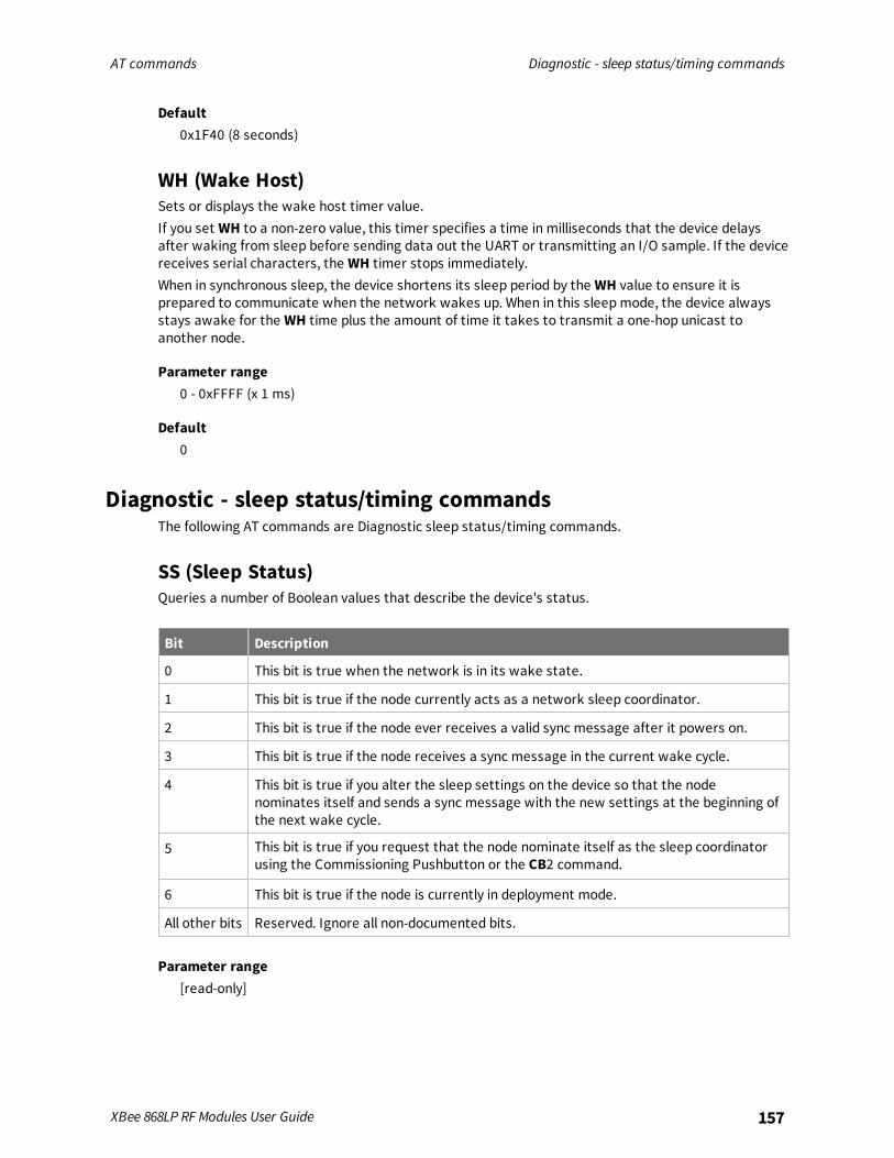
AT commands Diagnostic - sleep status/timing commands
XBee 868LP RF Modules User Guide 157
Default0x1F40 (8 seconds)
WH (Wake Host)Sets or displays the wake host timer value.If you set WH to a non-zero value, this timer specifies a time in milliseconds that the device delaysafter waking from sleep before sending data out the UART or transmitting an I/O sample. If the devicereceives serial characters, the WH timer stops immediately.When in synchronous sleep, the device shortens its sleep period by the WH value to ensure it isprepared to communicate when the network wakes up. When in this sleepmode, the device alwaysstays awake for the WH time plus the amount of time it takes to transmit a one-hop unicast toanother node.
Parameter range0 - 0xFFFF (x 1 ms)
Default0
Diagnostic - sleep status/timing commandsThe following AT commands are Diagnostic sleep status/timing commands.
SS (Sleep Status)Queries a number of Boolean values that describe the device's status.
Bit Description
0 This bit is true when the network is in its wake state.
1 This bit is true if the node currently acts as a network sleep coordinator.
2 This bit is true if the node ever receives a valid sync message after it powers on.
3 This bit is true if the node receives a sync message in the current wake cycle.
4 This bit is true if you alter the sleep settings on the device so that the nodenominates itself and sends a sync message with the new settings at the beginning ofthe next wake cycle.
5 This bit is true if you request that the node nominate itself as the sleep coordinatorusing the Commissioning Pushbutton or the CB2 command.
6 This bit is true if the node is currently in deployment mode.
All other bits Reserved. Ignore all non-documented bits.
Parameter range[read-only]
AT commands Diagnostic - sleep status/timing commands
XBee 868LP RF Modules User Guide 158
Default0x40
OS (Operating Sleep Time)Reads the current network sleep time that the device is synchronized to, in units of 10 milliseconds. Ifthe device has not been synchronized, thenOS returns the value of SP.If the device synchronizes with a sleeping router network,OSmay differ from SP.
Parameter range[read-only]
Default0x190
OW (Operating Wake Time)Reads the current network wake time that a device is synchronized to, in 1 ms units.If the device has not been synchronized, thenOW returns the value of ST.If the device synchronizes with a sleeping router network,OW may differ from ST.
Parameter range[read-only]
Default0
MS (Missed Sync Messages)Reads the number of sleep or wake cycles since the device received a sync message.Supported in the 80k firmware only.
Parameter range[read-only]
Default0
SQ (Missed Sleep Sync Count)Counts the number of sleep cycles in which the device does not receive a sleep sync.Set the value to 0 to reset this value.When the value reaches 0xFFFF it does not increment anymore.
Parameter range0 - 0xFFFF
Default0
AT commands Command mode options
XBee 868LP RF Modules User Guide 159
Command mode optionsThe following commands are Commandmode option commands.
CC (Command Sequence Character)Sets or displays the character the device uses between guard times of the Commandmode sequence.The Commandmode sequence causes the device to enter Commandmode (from Idle mode).
Note We recommend using the a value within the rage of 0x20 - 0x7F as those are ASCII characters.
Parameter range0 - 0xFF
Default0x2B (the ASCII plus character: +)
CT commandSets or displays the Commandmode timeout parameter. If a device does not receive any validcommands within this time period, it returns to Idle mode from Commandmode.
Parameter range2 - 0x1770 (x 100 ms)
Default0x64 (10 seconds)
CN commandImmediately exits Command Mode and applies pending changes.
Parameter rangeN/A
DefaultN/A
GT commandSet the required period of silence before and after the command sequence characters of theCommandmode sequence (GT + CC + GT). The period of silence prevents inadvertently enteringCommandmode.
Parameter range0x2 - 0x95C (x 1 ms)
Default0x3E8 (one second)

AT commands Firmware commands
XBee 868LP RF Modules User Guide 160
Firmware commandsThe following AT commands are firmware commands.
VL commandShows detailed version information including the application build date and time.
Parameter range[read-only]Multi-line string [read-only]
DefaultN/A
VR commandReads the firmware version on a device.
Parameter range0 - 0xFFFFFFFF [read-only]
DefaultSet in firmware
HV commandDisplay the hardware version number of the device.
Parameter range0 - 0xFFFF [read-only]
DefaultSet in firmware
HS (Hardware Series)Read the device's hardware series number.For example, if the device is version S8B, this returns 0x801.
Parameter range0 - 0xFFFF [read-only]
DefaultSet in the firmware
DD commandStores the Digi device type identifier value. Use this value to differentiate between multiple XBeedevices.

AT commands Firmware commands
XBee 868LP RF Modules User Guide 161
Parameter range0 - 0xFFFFFFFF [read-only]
Default0xC0000
NP (Maximum Packet Payload Bytes)Reads the maximum number of RF payload bytes that you can send in a transmission.
Parameter range0 - 0xFFFF (bytes) [read-only]
Default0x100
CK (Configuration CRC)Displays the cyclic redundancy check (CRC) of the current AT command configuration settings.This command allows you to detect an unexpected configuration change on a device.After a firmware update this commandmay return a different value.
Parameter rangeN/A
DefaultN/A

Operate in API mode
API mode overview 163Frame data 168
XBee 868LP RF Modules User Guide 162
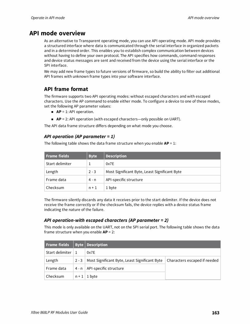
Operate in API mode API mode overview
XBee 868LP RF Modules User Guide 163
API mode overviewAs an alternative to Transparent operating mode, you can use API operating mode. API mode providesa structured interface where data is communicated through the serial interface in organized packetsand in a determined order. This enables you to establish complex communication between deviceswithout having to define your own protocol. The API specifies how commands, command responsesand device status messages are sent and received from the device using the serial interface or theSPI interface.We may add new frame types to future versions of firmware, so build the ability to filter out additionalAPI frames with unknown frame types into your software interface.
API frame formatThe firmware supports two API operating modes: without escaped characters and with escapedcharacters. Use the AP command to enable either mode. To configure a device to one of these modes,set the following AP parameter values:
n AP = 1: API operation.
n AP = 2: API operation (with escaped characters—only possible on UART).
The API data frame structure differs depending on what mode you choose.
API operation (AP parameter = 1)The following table shows the data frame structure when you enable AP = 1:
Frame fields Byte Description
Start delimiter 1 0x7E
Length 2 - 3 Most Significant Byte, Least Significant Byte
Frame data 4 - n API-specific structure
Checksum n + 1 1 byte
The firmware silently discards any data it receives prior to the start delimiter. If the device does notreceive the frame correctly or if the checksum fails, the device replies with a device status frameindicating the nature of the failure.
API operation-with escaped characters (AP parameter = 2)This mode is only available on the UART, not on the SPI serial port. The following table shows the dataframe structure when you enable AP = 2:
Frame fields Byte Description
Start delimiter 1 0x7E
Length 2 - 3 Most Significant Byte, Least Significant Byte Characters escaped if needed
Frame data 4 - n API-specific structure
Checksum n + 1 1 byte
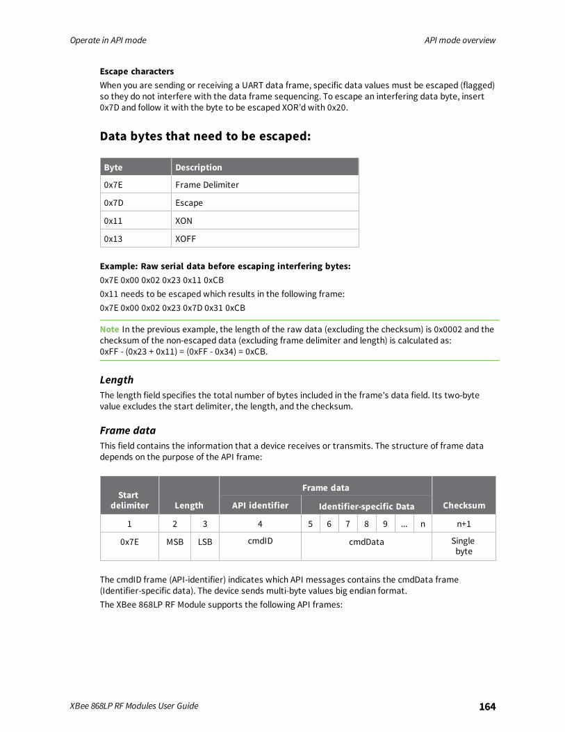
Operate in API mode API mode overview
XBee 868LP RF Modules User Guide 164
Escape charactersWhen you are sending or receiving a UART data frame, specific data values must be escaped (flagged)so they do not interfere with the data frame sequencing. To escape an interfering data byte, insert0x7D and follow it with the byte to be escaped XOR’d with 0x20.
Data bytes that need to be escaped:
Byte Description
0x7E Frame Delimiter
0x7D Escape
0x11 XON
0x13 XOFF
Example: Raw serial data before escaping interfering bytes:0x7E 0x00 0x02 0x23 0x11 0xCB0x11 needs to be escaped which results in the following frame:0x7E 0x00 0x02 0x23 0x7D 0x31 0xCB
Note In the previous example, the length of the raw data (excluding the checksum) is 0x0002 and thechecksum of the non-escaped data (excluding frame delimiter and length) is calculated as:0xFF - (0x23 + 0x11) = (0xFF - 0x34) = 0xCB.
LengthThe length field specifies the total number of bytes included in the frame's data field. Its two-bytevalue excludes the start delimiter, the length, and the checksum.
Frame dataThis field contains the information that a device receives or transmits. The structure of frame datadepends on the purpose of the API frame:
Startdelimiter Length
Frame data
ChecksumAPI identifier Identifier-specific Data
1 2 3 4 5 6 7 8 9 ... n n+1
0x7E MSB LSB cmdID cmdData Singlebyte
The cmdID frame (API-identifier) indicates which API messages contains the cmdData frame(Identifier-specific data). The device sends multi-byte values big endian format.The XBee 868LP RF Module supports the following API frames:
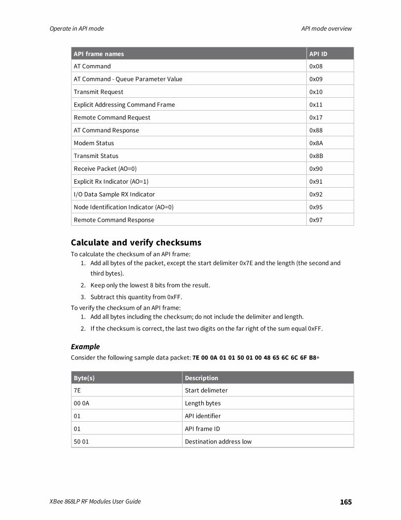
Operate in API mode API mode overview
XBee 868LP RF Modules User Guide 165
API frame names API ID
AT Command 0x08
AT Command - Queue Parameter Value 0x09
Transmit Request 0x10
Explicit Addressing Command Frame 0x11
Remote Command Request 0x17
AT Command Response 0x88
Modem Status 0x8A
Transmit Status 0x8B
Receive Packet (AO=0) 0x90
Explicit Rx Indicator (AO=1) 0x91
I/O Data Sample RX Indicator 0x92
Node Identification Indicator (AO=0) 0x95
Remote Command Response 0x97
Calculate and verify checksumsTo calculate the checksum of an API frame:
1. Add all bytes of the packet, except the start delimiter 0x7E and the length (the second andthird bytes).
2. Keep only the lowest 8 bits from the result.
3. Subtract this quantity from 0xFF.
To verify the checksum of an API frame:1. Add all bytes including the checksum; do not include the delimiter and length.
2. If the checksum is correct, the last two digits on the far right of the sum equal 0xFF.
ExampleConsider the following sample data packet: 7E 00 0A 01 01 50 01 00 48 65 6C 6C 6F B8+
Byte(s) Description
7E Start delimeter
00 0A Length bytes
01 API identifier
01 API frame ID
50 01 Destination address low
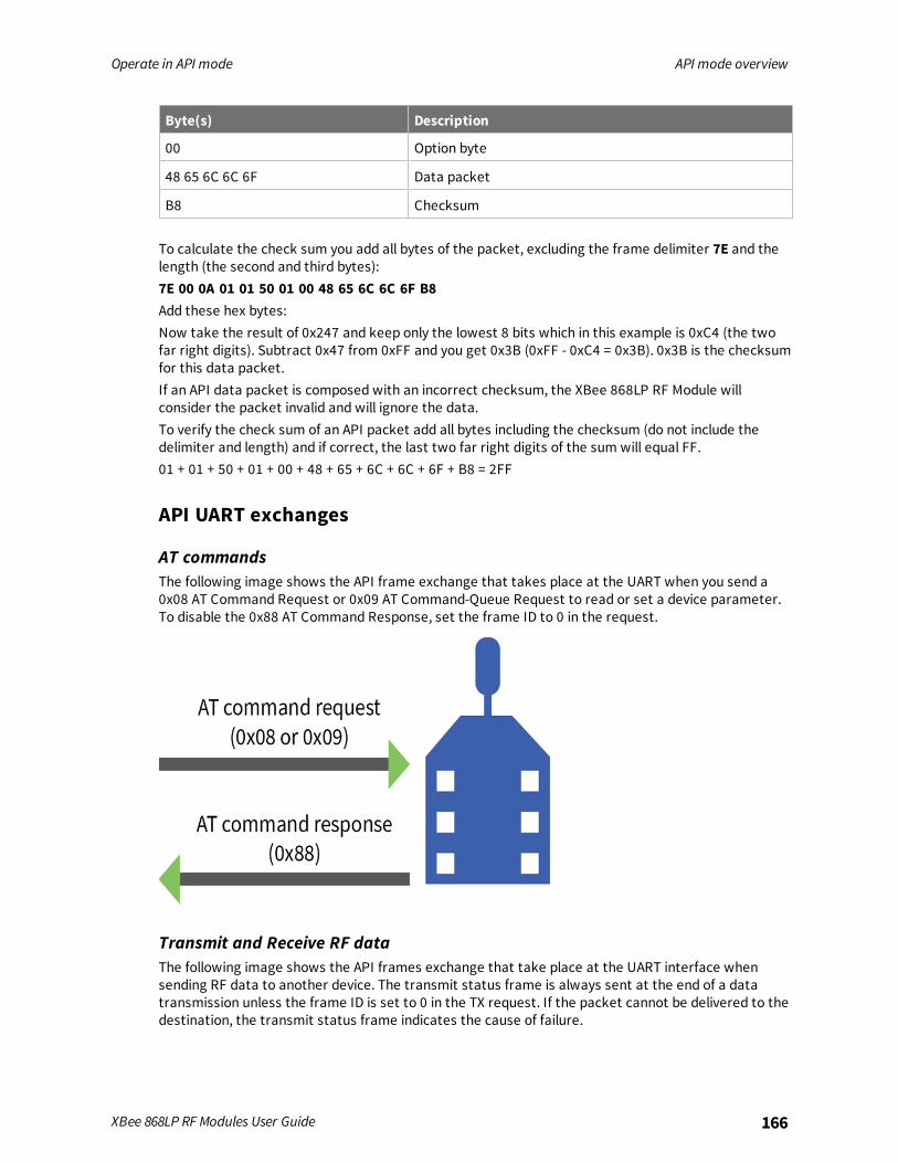
Operate in API mode API mode overview
XBee 868LP RF Modules User Guide 166
Byte(s) Description
00 Option byte
48 65 6C 6C 6F Data packet
B8 Checksum
To calculate the check sum you add all bytes of the packet, excluding the frame delimiter 7E and thelength (the second and third bytes):7E 00 0A 01 01 50 01 00 48 65 6C 6C 6F B8Add these hex bytes:Now take the result of 0x247 and keep only the lowest 8 bits which in this example is 0xC4 (the twofar right digits). Subtract 0x47 from 0xFF and you get 0x3B (0xFF - 0xC4 = 0x3B). 0x3B is the checksumfor this data packet.If an API data packet is composed with an incorrect checksum, the XBee 868LP RF Module willconsider the packet invalid and will ignore the data.To verify the check sum of an API packet add all bytes including the checksum (do not include thedelimiter and length) and if correct, the last two far right digits of the sum will equal FF.01 + 01 + 50 + 01 + 00 + 48 + 65 + 6C + 6C + 6F + B8 = 2FF
API UART exchanges
AT commandsThe following image shows the API frame exchange that takes place at the UART when you send a0x08 AT Command Request or 0x09 AT Command-Queue Request to read or set a device parameter.To disable the 0x88 AT Command Response, set the frame ID to 0 in the request.
Transmit and Receive RF dataThe following image shows the API frames exchange that take place at the UART interface whensending RF data to another device. The transmit status frame is always sent at the end of a datatransmission unless the frame ID is set to 0 in the TX request. If the packet cannot be delivered to thedestination, the transmit status frame indicates the cause of failure.
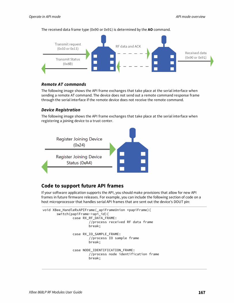
Operate in API mode API mode overview
XBee 868LP RF Modules User Guide 167
The received data frame type (0x90 or 0x91) is determined by the AO command.
Remote AT commandsThe following image shows the API frame exchanges that take place at the serial interface whensending a remote AT command. The device does not send out a remote command response framethrough the serial interface if the remote device does not receive the remote command.
Device RegistrationThe following image shows the API frame exchanges that take place at the serial interface whenregistering a joining device to a trust center.
Code to support future API framesIf your software application supports the API, you should make provisions that allow for new APIframes in future firmware releases. For example, you can include the following section of code on ahost microprocessor that handles serial API frames that are sent out the device's DOUT pin:
void XBee_HandleRxAPIFrame(_apiFrameUnion *papiFrame)switch(papiFrame->api_id)
case RX_RF_DATA_FRAME://process received RF data framebreak;
case RX_IO_SAMPLE_FRAME://process IO sample framebreak;
case NODE_IDENTIFICATION_FRAME://process node identification framebreak;

Operate in API mode Frame data
XBee 868LP RF Modules User Guide 168
default://Discard any other API frame types that are not being usedbreak;
Frame dataThis field contains the information that a device receives or will transmit. The structure of frame datadepends on the purpose of the API frame:
Length
Frame data
Data
1 2 3 4 5 6 7 8 9 ... n n+1
0x7E MSB LSB Data
n Frame type is the API frame type identifier. It determines the type of API frame and indicateshow the Data field organizes the information.
n Data contains the data itself. This information and its order depend on the what type of framethat the Frame type field defines.
Multi-byte values are sent big-endian.
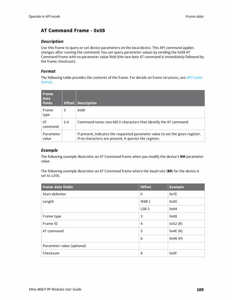
Operate in API mode Frame data
XBee 868LP RF Modules User Guide 169
AT Command Frame - 0x08
DescriptionUse this frame to query or set device parameters on the local device. This API command applieschanges after running the command. You can query parameter values by sending the 0x08 ATCommand frame with no parameter value field (the two-byte AT command is immediately followed bythe frame checksum).
FormatThe following table provides the contents of the frame. For details on frame structure, see API frameformat.
Framedatafields Offset Description
Frametype
3 0x08
ATcommand
5-6 Command name: two ASCII characters that identify the AT command.
Parametervalue
If present, indicates the requested parameter value to set the given register.If no characters are present, it queries the register.
ExampleThe following example illustrates an AT Command frame when you modify the device's NH parametervalue.
The following example illustrates an AT Command frame where the baud rate (BD) for the device isset to 1200.
Frame data fields Offset Example
Start delimiter 0 0x7E
Length MSB 1 0x00
LSB 2 0x04
Frame type 3 0x08
Frame ID 4 0x52 (R)
AT command 5 0x4E (N)
6 0x48 (H)
Parameter value (optional)
Checksum 8 0x0F

Operate in API mode Frame data
XBee 868LP RF Modules User Guide 170
AT Command - Queue Parameter Value frame - 0x09
DescriptionThis frame allows you to query or set device parameters. In contrast to the AT Command (0x08)frame, this frame queues new parameter values and does not apply them until you issue either:
n The AT Command (0x08) frame (for API type)
n The AC command
FormatThe following table provides the contents of the frame. For details on frame structure, see API frameformat.
Frame datafields Offset Description
Frame type 3 0x09
Frame ID 4 Identifies the data frame for the host to correlate with a subsequentACK. If set to 0, the device does not send a response.
AT command 5-6 Command name: two ASCII characters that identify the AT command.
Parameter value 7-n If present, indicates the requested parameter value to set the givenregister. If no characters are present, queries the register.
ExampleThe following example sends a command to change the baud rate (BD) to 115200 baud, but does notapply the changes immediately. The device continues to operate at the previous baud rate until youapply the changes.
Note In this example, you could send the parameter as a zero-padded 2-byte or 4-byte value.
Frame data fields
Start delimiter 0 0x7E
Length MSB 1 0x00
LSB 2 0x05
Frame type 3 0x09
Frame ID 4 0x01
AT command 5 0x42 (B)
6 0x44 (D)
Parameter value (BD7 = 115200 baud) 0x07
Checksum 8 0x68

Operate in API mode Frame data
XBee 868LP RF Modules User Guide 171
Transmit Request frame - 0x10
DescriptionThis frame causes the device to send payload data as an RF packet to a specific destination.
n For broadcast transmissions, set the 64-bit destination address to 0x000000000000FFFF forall devices.
n For unicast transmissions, set the 64 bit address field to the address of the desired destinationnode.
n Set the reserved field to 0xFFFE.
FormatThe following table provides the contents of the frame. For details on the frame structure, see APIframe format.
Frame datafields Offset Description
Frame type 3 0x10
Frame ID 4 Identifies the data frame for the host to correlate with a subsequent ACK.If set to 0, the device does not send a response.
64-bitdestinationaddress
5-12 MSB first, LSB last. Set to the 64-bit address of the destination device.Broadcast = 0x000000000000FFFF
Reserved 13-14 Set to 0xFFFE.
Broadcastradius
15 Sets the maximum number of hops a broadcast transmission can occur. Ifset to 0, the broadcast radius is set to the maximum hops value.
Transmitoptions
16 See the following Transmit Options table.
RF data 17-n Up to NP bytes per packet. Sent to the destination device.
Transmit Options bit fieldBit field:
Bit Meaning Description
0 Disable ACK Disable acknowledgments on all unicasts.
1 Disable RD Disable Route Discovery.
2 NACK Enable unicast NACK messages.
3 Trace route Enable unicast trace route messages.

Operate in API mode Frame data
XBee 868LP RF Modules User Guide 172
Bit Meaning Description
6,7 Delivery method b’00 = <invalid option>b’01 - Point-multipointb’10 = Repeater mode (directed broadcast)b’11 = DigiMesh (not available on the 10k product)
Example
The example shows how to send a transmission to a device if you disable escaping (AP = 1), withdestination address 0x0013A200 40014011, and payload “TxData0A”.
Frame data fields Offset Example
Start delimiter 0 0x7E
Length MSB 1 0x00
LSB 2 0x16
Frame type 3 0x10
Frame ID 4 0x01
64-bit destinationaddress
MSB 5 0x00
6 0x13
7 0xA2
8 0x00
9 0x40
10 0x0A
11 0x01
LSB 12 0x27
Reserved MSB 13 0xFF
LSB 14 0xFE
Broadcast radius 15 0x00
Options 16 0x00

Operate in API mode Frame data
XBee 868LP RF Modules User Guide 173
Frame data fields Offset Example
RF data 17 0x54
18 0x78
19 0x44
20 0x61
21 0x74
22 0x61
23 0x30
24 0x41
Checksum 25 0x13
If you enable escaping (AP = 2), the frame should look like:0x7E 0x00 0x16 0x10 0x01 0x00 0x7D 0x33 0xA2 0x00 0x40 0x0A 0x01 0x27 0xFF 0xFE 0x000x00 0x54 0x78 0x44 0x61 0x74 0x61 0x30 0x41 0x7D 0x33
The device calculates the checksum (on all non-escaped bytes) as [0xFF - (sum of all bytes from APIframe type through data payload)].
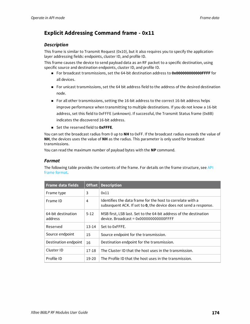
Operate in API mode Frame data
XBee 868LP RF Modules User Guide 174
Explicit Addressing Command frame - 0x11
DescriptionThis frame is similar to Transmit Request (0x10), but it also requires you to specify the application-layer addressing fields: endpoints, cluster ID, and profile ID.This frame causes the device to send payload data as an RF packet to a specific destination, usingspecific source and destination endpoints, cluster ID, and profile ID.
n For broadcast transmissions, set the 64-bit destination address to 0x000000000000FFFF forall devices.
n For unicast transmissions, set the 64 bit address field to the address of the desired destinationnode.
n For all other transmissions, setting the 16-bit address to the correct 16-bit address helpsimprove performance when transmitting to multiple destinations. If you do not know a 16-bitaddress, set this field to 0xFFFE (unknown). If successful, the Transmit Status frame (0x8B)indicates the discovered 16-bit address.
n Set the reserved field to 0xFFFE.You can set the broadcast radius from 0 up to NH to 0xFF. If the broadcast radius exceeds the value ofNH, the devices uses the value of NH as the radius. This parameter is only used for broadcasttransmissions.You can read the maximum number of payload bytes with the NP command.
FormatThe following table provides the contents of the frame. For details on the frame structure, see APIframe format.
Frame data fields Offset Description
Frame type 3 0x11
Frame ID 4 Identifies the data frame for the host to correlate with asubsequent ACK. If set to 0, the device does not send a response.
64-bit destinationaddress
5-12 MSB first, LSB last. Set to the 64-bit address of the destinationdevice. Broadcast = 0x000000000000FFFF
Reserved 13-14 Set to 0xFFFE.
Source endpoint 15 Source endpoint for the transmission.
Destination endpoint 16 Destination endpoint for the transmission.
Cluster ID 17-18 The Cluster ID that the host uses in the transmission.
Profile ID 19-20 The Profile ID that the host uses in the transmission.
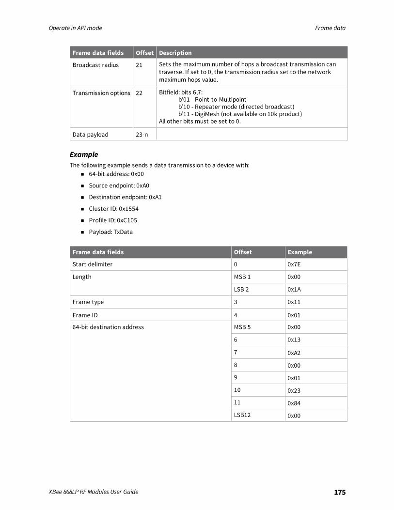
Operate in API mode Frame data
XBee 868LP RF Modules User Guide 175
Frame data fields Offset Description
Broadcast radius 21 Sets the maximum number of hops a broadcast transmission cantraverse. If set to 0, the transmission radius set to the networkmaximum hops value.
Transmission options 22 Bitfield: bits 6,7:b’01 - Point-to-Multipointb’10 - Repeater mode (directed broadcast)b’11 - DigiMesh (not available on 10k product)
All other bits must be set to 0.
Data payload 23-n
ExampleThe following example sends a data transmission to a device with:
n 64-bit address: 0x00
n Source endpoint: 0xA0
n Destination endpoint: 0xA1
n Cluster ID: 0x1554
n Profile ID: 0xC105
n Payload: TxData
Frame data fields Offset Example
Start delimiter 0 0x7E
Length MSB 1 0x00
LSB 2 0x1A
Frame type 3 0x11
Frame ID 4 0x01
64-bit destination address MSB 5 0x00
6 0x13
7 0xA2
8 0x00
9 0x01
10 0x23
11 0x84
LSB12 0x00

Operate in API mode Frame data
XBee 868LP RF Modules User Guide 176
Frame data fields Offset Example
Reserved MSB 13 0xFF
LSB 14 0xFE
Source endpoint 15 0xA0
Destination endpoint 16 0xA1
Cluster ID 17 0x15
18 0x54
Profile ID 19 0xC1
20 0x05
Broadcast radius 21 0x00
Transmit options 22 0x00
Data payload 23 0x54
24 0x78
25 0x44
26 0x61
27 0x74
28 0x61
Checksum 29 0xDD

Operate in API mode Frame data
XBee 868LP RF Modules User Guide 177
Remote AT Command Request frame - 0x17
DescriptionUsed to query or set device parameters on a remote device. For parameter changes on the remotedevice to take effect, you must apply changes, either by setting the Apply Changes options bit, or bysending an AC command to the remote.
FormatThe following table provides the contents of the frame. For details on frame structure, see API frameformat.
Frame datafields Offset Description
Frame type 3 0x17
Frame ID 4 Identifies the UART data frame for the host to correlate with asubsequent ACK. If set to 0, the device does not send a response.
64-bitdestinationaddress
5-12 MSB first, LSB last. Set to the 64-bit address of the destination device.Broadcast = 0x000000000000FFFF.
Reserved 13-14 Set to 0xFFFE.
Remotecommandoptions
15 0x02 = Apply changes on remote. If you do not set this, you must send theAC command for changes to take effect.Set all other bits to 0.
AT command 16-17 Command name: two ASCII characters that identify the command.
Commandparameter
18-n If present, indicates the parameter value you request for a given register.If no characters are present, it queries the register.
ExampleThe following example sends a remote command:
n Change the broadcast hops register on a remote device to 1 (broadcasts go to 1-hop neighborsonly).
n Apply changes so the new configuration value takes effect immediately.
In this example, the 64-bit address of the remote device is 0x0013A200 40401122.
Frame data fields Offset Example
Start delimiter 0 0x7E
Length MSB 1 0x00
LSB 2 0x10
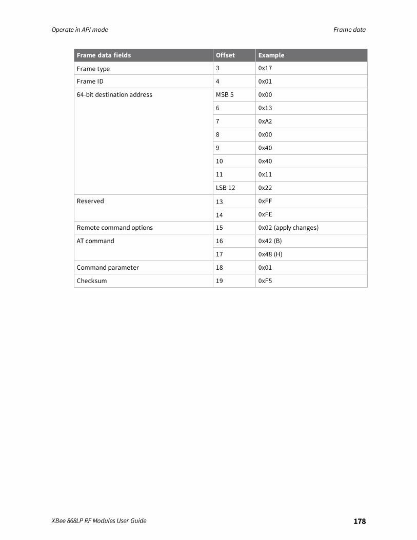
Operate in API mode Frame data
XBee 868LP RF Modules User Guide 178
Frame data fields Offset Example
Frame type 3 0x17
Frame ID 4 0x01
64-bit destination address MSB 5 0x00
6 0x13
7 0xA2
8 0x00
9 0x40
10 0x40
11 0x11
LSB 12 0x22
Reserved 13 0xFF
14 0xFE
Remote command options 15 0x02 (apply changes)
AT command 16 0x42 (B)
17 0x48 (H)
Command parameter 18 0x01
Checksum 19 0xF5
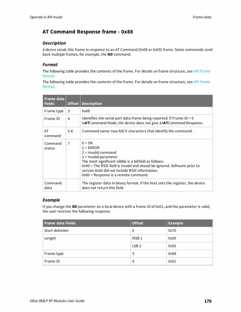
Operate in API mode Frame data
XBee 868LP RF Modules User Guide 179
AT Command Response frame - 0x88
DescriptionA device sends this frame in response to an AT Command (0x08 or 0x09) frame. Some commands sendback multiple frames; for example, the ND command.
FormatThe following table provides the contents of the frame. For details on frame structure, see API frameformat.The following table provides the contents of the frame. For details on frame structure, see API frameformat.
Frame datafields Offset Description
Frame type 3 0x88
Frame ID 4 Identifies the serial port data frame being reported. If Frame ID = 0inATCommand Mode, the device does not give anATCommand Response.
ATcommand
5-6 Command name: two ASCII characters that identify the command.
Commandstatus
7 0 = OK1 = ERROR2 = Invalid command3 = Invalid parameterThe most significant nibble is a bitfield as follows:0x40 = The RSSI field is invalid and should be ignored. Software prior toversion 8x60 did not include RSSI information.0x80 = Response is a remote command.
Commanddata
The register data in binary format. If the host sets the register, the devicedoes not return this field.
ExampleIf you change the BD parameter on a local device with a frame ID of 0x01, and the parameter is valid,the user receives the following response.
Frame data fields Offset Example
Start delimiter 0 0x7E
Length MSB 1 0x00
LSB 2 0x05
Frame type 3 0x88
Frame ID 4 0x01
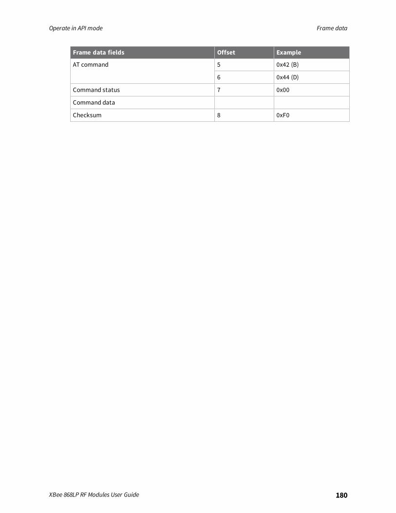
Operate in API mode Frame data
XBee 868LP RF Modules User Guide 180
Frame data fields Offset Example
AT command 5 0x42 (B)
6 0x44 (D)
Command status 7 0x00
Command data
Checksum 8 0xF0

Operate in API mode Frame data
XBee 868LP RF Modules User Guide 181
Modem Status frame - 0x8A
DescriptionDevices send the status messages in this frame in response to specific conditions.
FormatThe following table provides the contents of the frame. For details on frame structure, see API frameformat.
Frame data fields Offset Description
Frame type 3 0x8A
Status 4 0x00 = Hardware reset0x01 = Watchdog timer reset0x0B = Network woke up0x0C = Network went to sleep
ExampleWhen a device powers up, it returns the following API frame.
Frame data fields Offset Example
Start delimiter 0 0x7E
Length MSB 1 0x00
LSB 2 LSB 2 0x02
Frame type 3 0x8A
Status 4 0x00
Checksum 5 0x75
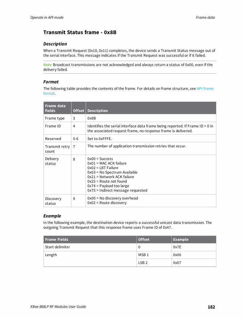
Operate in API mode Frame data
XBee 868LP RF Modules User Guide 182
Transmit Status frame - 0x8B
DescriptionWhen a Transmit Request (0x10, 0x11) completes, the device sends a Transmit Status message out ofthe serial interface. This message indicates if the Transmit Request was successful or if it failed.
Note Broadcast transmissions are not acknowledged and always return a status of 0x00, even if thedelivery failed.
FormatThe following table provides the contents of the frame. For details on frame structure, see API frameformat.
Frame datafields Offset Description
Frame type 3 0x8B
Frame ID 4 Identifies the serial interface data frame being reported. If Frame ID = 0 inthe associated request frame, no response frame is delivered.
Reserved 5-6 Set to 0xFFFE.
Transmit retrycount
7 The number of application transmission retries that occur.
Deliverystatus
8 0x00 = Success0x01 = MAC ACK failure0x02 = LBT Failure0x03 = No Spectrum Available0x21 = Network ACK failure0x25 = Route not found0x74 = Payload too large0x75 = Indirect message requested
Discoverystatus
9 0x00 = No discovery overhead0x02 = Route discovery
ExampleIn the following example, the destination device reports a successful unicast data transmission. Theoutgoing Transmit Request that this response frame uses Frame ID of 0x47.
Frame Fields Offset Example
Start delimiter 0 0x7E
Length MSB 1 0x00
LSB 2 0x07

Operate in API mode Frame data
XBee 868LP RF Modules User Guide 183
Frame Fields Offset Example
Frame type 3 0x8B
Frame ID 4 0x47
Reserved 5 0xFF
6 0xFE
Transmit retry count 7 0x00
Delivery status 8 0x00
Discovery status 9 0x02
Checksum 10 0x2E
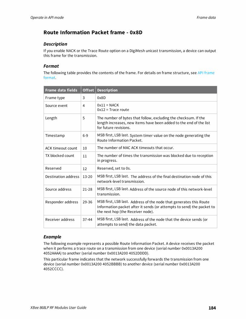
Operate in API mode Frame data
XBee 868LP RF Modules User Guide 184
Route Information Packet frame - 0x8D
DescriptionIf you enable NACK or the Trace Route option on a DigiMesh unicast transmission, a device can outputthis frame for the transmission.
FormatThe following table provides the contents of the frame. For details on frame structure, see API frameformat.
Frame data fields Offset Description
Frame type 3 0x8D
Source event 4 0x11 = NACK0x12 = Trace route
Length 5 The number of bytes that follow, excluding the checksum. If thelength increases, new items have been added to the end of the listfor future revisions.
Timestamp 6-9 MSB first, LSB last. System timer value on the node generating theRoute Information Packet.
ACK timeout count 10 The number of MAC ACK timeouts that occur.
TX blocked count 11 The number of times the transmission was blocked due to receptionin progress.
Reserved 12 Reserved, set to 0s.
Destination address 13-20 MSB first, LSB last. The address of the final destination node of thisnetwork-level transmission.
Source address 21-28 MSB first, LSB last. Address of the source node of this network-leveltransmission.
Responder address 29-36 MSB first, LSB last. Address of the node that generates this RouteInformation packet after it sends (or attempts to send) the packet tothe next hop (the Receiver node).
Receiver address 37-44 MSB first, LSB last. Address of the node that the device sends (orattempts to send) the data packet.
ExampleThe following example represents a possible Route Information Packet. A device receives the packetwhen it performs a trace route on a transmission from one device (serial number 0x0013A2004052AAAA) to another (serial number 0x0013A200 4052DDDD).This particular frame indicates that the network successfully forwards the transmission from onedevice (serial number 0x0013A200 4052BBBB) to another device (serial number 0x0013A2004052CCCC).
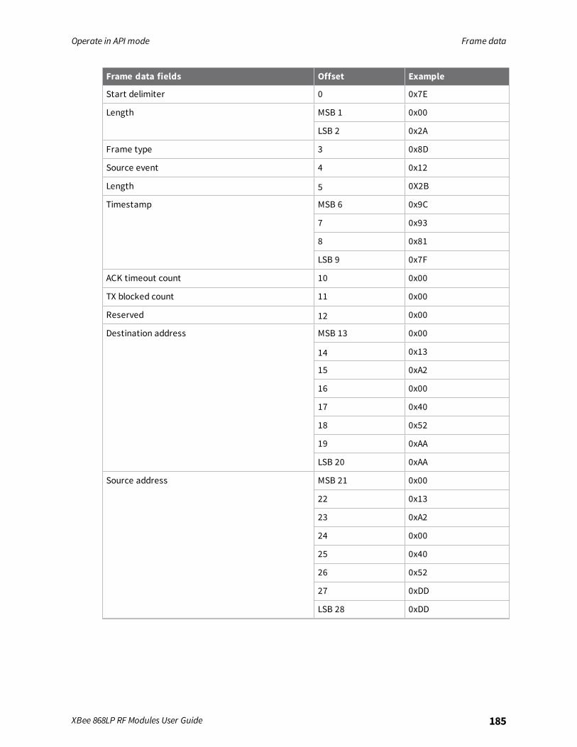
Operate in API mode Frame data
XBee 868LP RF Modules User Guide 185
Frame data fields Offset Example
Start delimiter 0 0x7E
Length MSB 1 0x00
LSB 2 0x2A
Frame type 3 0x8D
Source event 4 0x12
Length 5 0X2B
Timestamp MSB 6 0x9C
7 0x93
8 0x81
LSB 9 0x7F
ACK timeout count 10 0x00
TX blocked count 11 0x00
Reserved 12 0x00
Destination address MSB 13 0x00
14 0x13
15 0xA2
16 0x00
17 0x40
18 0x52
19 0xAA
LSB 20 0xAA
Source address MSB 21 0x00
22 0x13
23 0xA2
24 0x00
25 0x40
26 0x52
27 0xDD
LSB 28 0xDD
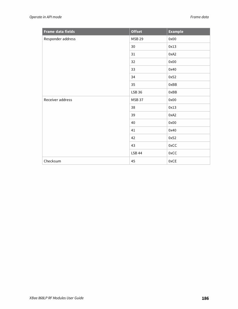
Operate in API mode Frame data
XBee 868LP RF Modules User Guide 186
Frame data fields Offset Example
Responder address MSB 29 0x00
30 0x13
31 0xA2
32 0x00
33 0x40
34 0x52
35 0xBB
LSB 36 0xBB
Receiver address MSB 37 0x00
38 0x13
39 0xA2
40 0x00
41 0x40
42 0x52
43 0xCC
LSB 44 0xCC
Checksum 45 0xCE
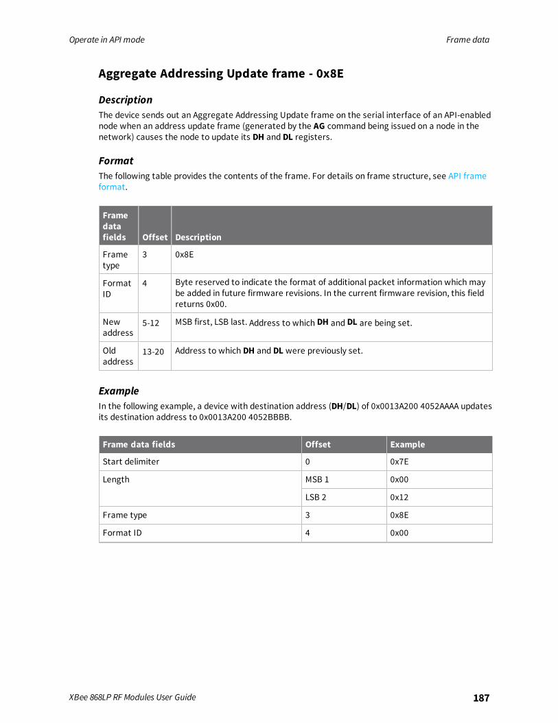
Operate in API mode Frame data
XBee 868LP RF Modules User Guide 187
Aggregate Addressing Update frame - 0x8E
DescriptionThe device sends out an Aggregate Addressing Update frame on the serial interface of an API-enablednode when an address update frame (generated by the AG command being issued on a node in thenetwork) causes the node to update its DH and DL registers.
FormatThe following table provides the contents of the frame. For details on frame structure, see API frameformat.
Framedatafields Offset Description
Frametype
3 0x8E
FormatID
4 Byte reserved to indicate the format of additional packet information which maybe added in future firmware revisions. In the current firmware revision, this fieldreturns 0x00.
Newaddress
5-12 MSB first, LSB last. Address to which DH and DL are being set.
Oldaddress
13-20 Address to which DH and DL were previously set.
ExampleIn the following example, a device with destination address (DH/DL) of 0x0013A200 4052AAAA updatesits destination address to 0x0013A200 4052BBBB.
Frame data fields Offset Example
Start delimiter 0 0x7E
Length MSB 1 0x00
LSB 2 0x12
Frame type 3 0x8E
Format ID 4 0x00

Operate in API mode Frame data
XBee 868LP RF Modules User Guide 188
Frame data fields Offset Example
New address MSB 5 0x00
6 0x13
7 0xA2
8 0x00
9 0x40
10 0x52
11 0xBB
LSB 12 0xBB
Old address 13 0x00
14 0x13
15 0xA2
16 0x00
17 0x40
18 0x52
19 0xAA
20 0xAA
Checksum 21 0x2E
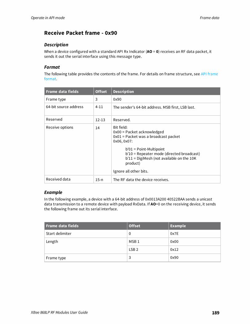
Operate in API mode Frame data
XBee 868LP RF Modules User Guide 189
Receive Packet frame - 0x90
DescriptionWhen a device configured with a standard API Rx Indicator (AO = 0) receives an RF data packet, itsends it out the serial interface using this message type.
FormatThe following table provides the contents of the frame. For details on frame structure, see API frameformat.
Frame data fields Offset Description
Frame type 3 0x90
64-bit source address 4-11 The sender's 64-bit address. MSB first, LSB last.
Reserved 12-13 Reserved.
Receive options 14 Bit field:0x00 = Packet acknowledged0x01 = Packet was a broadcast packet0x06, 0x07:
b’01 = Point-Multipointb’10 = Repeater mode (directed broadcast)b’11 = DigiMesh (not available on the 10Kproduct)
Ignore all other bits.
Received data 15-n The RF data the device receives.
ExampleIn the following example, a device with a 64-bit address of 0x0013A200 40522BAA sends a unicastdata transmission to a remote device with payload RxData. If AO=0 on the receiving device, it sendsthe following frame out its serial interface.
Frame data fields Offset Example
Start delimiter 0 0x7E
Length MSB 1 0x00
LSB 2 0x12
Frame type 3 0x90
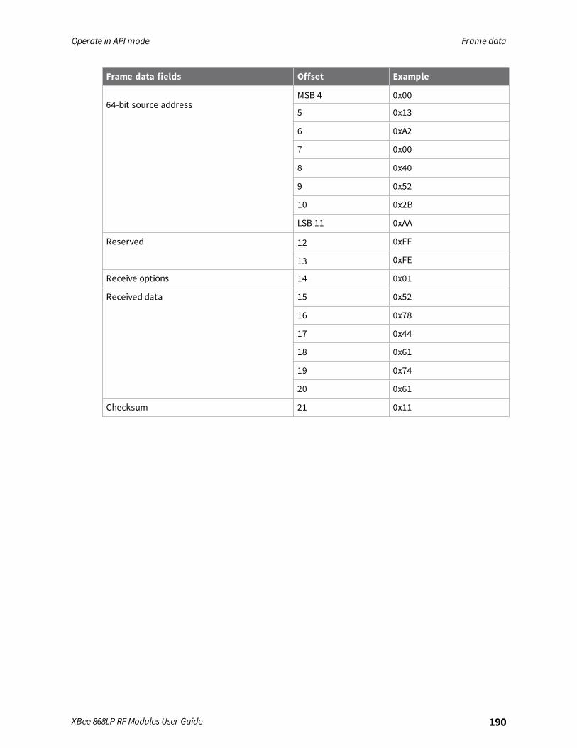
Operate in API mode Frame data
XBee 868LP RF Modules User Guide 190
Frame data fields Offset Example
64-bit source addressMSB 4 0x00
5 0x13
6 0xA2
7 0x00
8 0x40
9 0x52
10 0x2B
LSB 11 0xAA
Reserved 12 0xFF
13 0xFE
Receive options 14 0x01
Received data 15 0x52
16 0x78
17 0x44
18 0x61
19 0x74
20 0x61
Checksum 21 0x11

Operate in API mode Frame data
XBee 868LP RF Modules User Guide 191
Explicit Rx Indicator frame - 0x91
DescriptionWhen a device configured with explicit API Rx Indicator (AO = 1) receives an RF packet, it sends it outthe serial interface using this message type.The Cluster ID and endpoints must be used to identify the type of transaction that occurred.
FormatThe following table provides the contents of the frame. For details on frame structure, see API frameformat.
Frame data fields Offset Description
Frame type 3 0x91
64-bit source address 4-11 MSB first, LSB last. The sender's 64-bit address.
Reserved 12-13 Reserved.
Source endpoint 14 Endpoint of the source that initiates transmission.
Destination endpoint 15 Endpoint of the destination where the message is addressed.
Cluster ID 16-17 The Cluster ID where the frame is addressed.
Profile ID 18-19 The Profile ID where the fame is addressed.
Receive options 20 Bit field:0x00 = Packet acknowledged0x01 = Packet was a broadcast packet0x06, 0x07:
b’01 = Point-Multipointb’10 = Repeater mode (directed broadcast)b’11 = DigiMesh (not available on the 10K product)
Ignore all other bits.
Received data 21-n Received RF data.
ExampleIn the following example, a device with a 64-bit address of 0x0013A200 40522BAA sends a broadcastdata transmission to a remote device with payload RxData.If a device sends the transmission:
n With source and destination endpoints of 0xE0
n Cluster ID = 0x2211
n Profile ID = 0xC105
If AO = 1 on the receiving device, it sends the following frame out its serial interface.
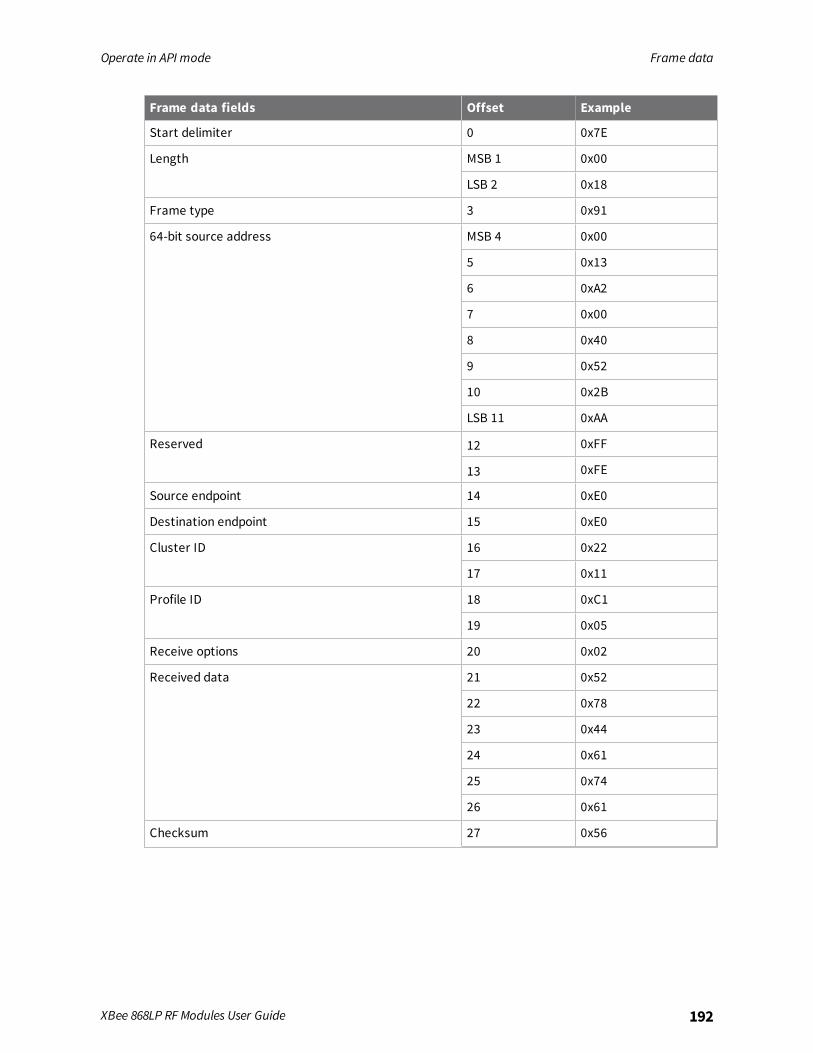
Operate in API mode Frame data
XBee 868LP RF Modules User Guide 192
Frame data fields Offset Example
Start delimiter 0 0x7E
Length MSB 1 0x00
LSB 2 0x18
Frame type 3 0x91
64-bit source address MSB 4 0x00
5 0x13
6 0xA2
7 0x00
8 0x40
9 0x52
10 0x2B
LSB 11 0xAA
Reserved 12 0xFF
13 0xFE
Source endpoint 14 0xE0
Destination endpoint 15 0xE0
Cluster ID 16 0x22
17 0x11
Profile ID 18 0xC1
19 0x05
Receive options 20 0x02
Received data 21 0x52
22 0x78
23 0x44
24 0x61
25 0x74
26 0x61
Checksum 27 0x56
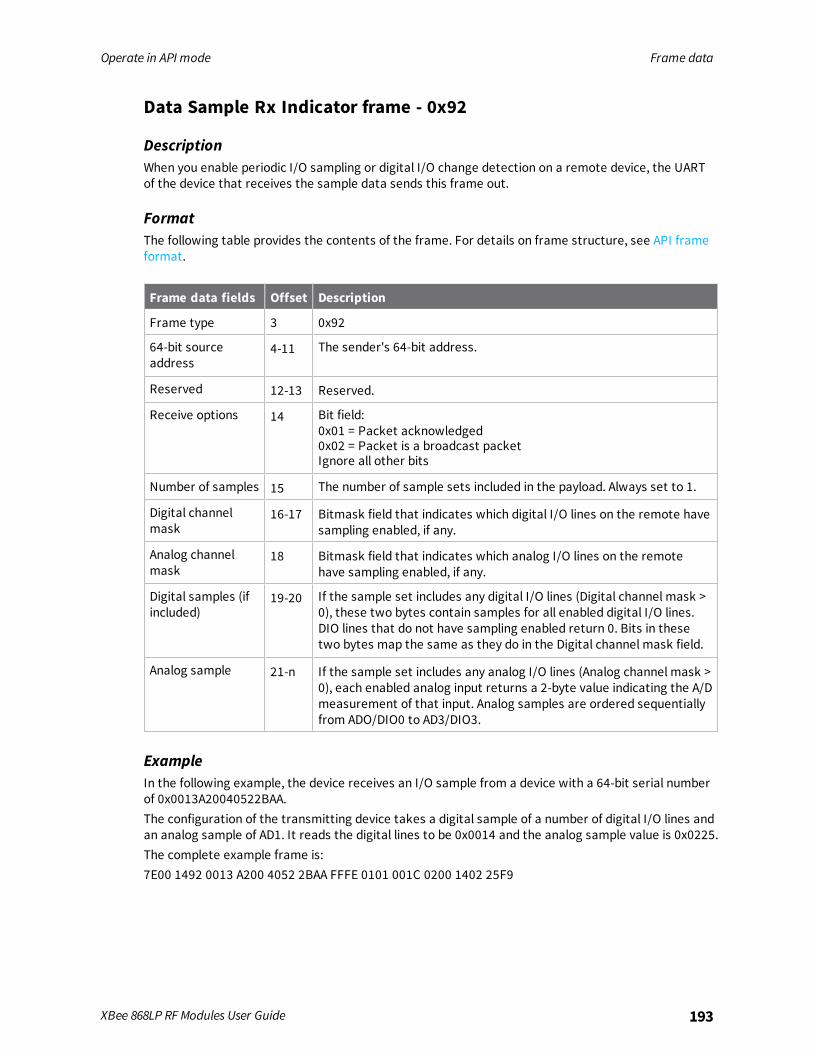
Operate in API mode Frame data
XBee 868LP RF Modules User Guide 193
Data Sample Rx Indicator frame - 0x92
DescriptionWhen you enable periodic I/O sampling or digital I/O change detection on a remote device, the UARTof the device that receives the sample data sends this frame out.
FormatThe following table provides the contents of the frame. For details on frame structure, see API frameformat.
Frame data fields Offset Description
Frame type 3 0x92
64-bit sourceaddress
4-11 The sender's 64-bit address.
Reserved 12-13 Reserved.
Receive options 14 Bit field:0x01 = Packet acknowledged0x02 = Packet is a broadcast packetIgnore all other bits
Number of samples 15 The number of sample sets included in the payload. Always set to 1.
Digital channelmask
16-17 Bitmask field that indicates which digital I/O lines on the remote havesampling enabled, if any.
Analog channelmask
18 Bitmask field that indicates which analog I/O lines on the remotehave sampling enabled, if any.
Digital samples (ifincluded)
19-20 If the sample set includes any digital I/O lines (Digital channel mask >0), these two bytes contain samples for all enabled digital I/O lines.DIO lines that do not have sampling enabled return 0. Bits in thesetwo bytes map the same as they do in the Digital channel mask field.
Analog sample 21-n If the sample set includes any analog I/O lines (Analog channel mask >0), each enabled analog input returns a 2-byte value indicating the A/Dmeasurement of that input. Analog samples are ordered sequentiallyfrom ADO/DIO0 to AD3/DIO3.
ExampleIn the following example, the device receives an I/O sample from a device with a 64-bit serial numberof 0x0013A20040522BAA.The configuration of the transmitting device takes a digital sample of a number of digital I/O lines andan analog sample of AD1. It reads the digital lines to be 0x0014 and the analog sample value is 0x0225.The complete example frame is:7E00 1492 0013 A200 4052 2BAA FFFE 0101 001C 0200 1402 25F9

Operate in API mode Frame data
XBee 868LP RF Modules User Guide 194
Frame fields Offset Example
Start delimiter 0 0x7E
Length MSB 1 0x00
LSB 2 0x14
Frame-specific data
64-bit source address MSB 4 0x00
5 0x13
6 0xA2
7 0x00
8 0x40
9 0x52
10 0x2B
LSB 11 0xAA
Reserved MSB 12 0xfffe
LSB 13 0x84
Receive options 14 0x01
Number of samples 15 0x01
Digital channel mask 16 0x00
17 0x1C
Analog channel mask 18 0x02
Digital samples (if included) 19 0x00
20 0x14
Analog sample 21 0x02
22 0x25
Checksum 23 0xF5
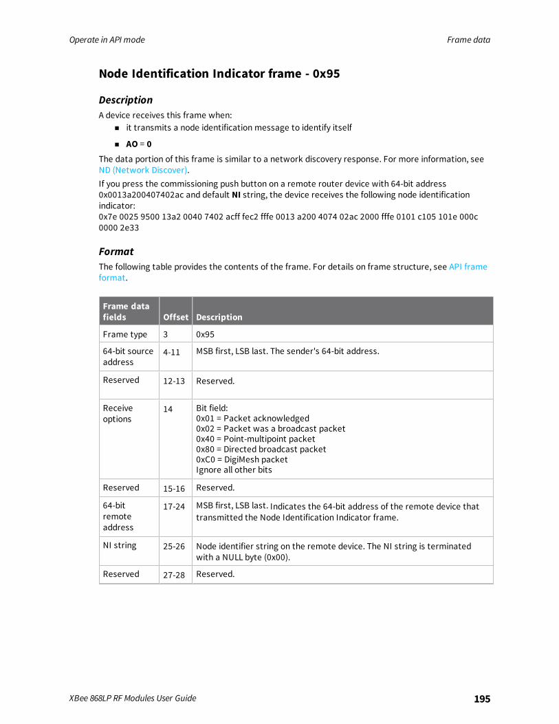
Operate in API mode Frame data
XBee 868LP RF Modules User Guide 195
Node Identification Indicator frame - 0x95
DescriptionA device receives this frame when:
n it transmits a node identification message to identify itself
n AO = 0The data portion of this frame is similar to a network discovery response. For more information, seeND (Network Discover).If you press the commissioning push button on a remote router device with 64-bit address0x0013a200407402ac and default NI string, the device receives the following node identificationindicator:0x7e 0025 9500 13a2 0040 7402 acff fec2 fffe 0013 a200 4074 02ac 2000 fffe 0101 c105 101e 000c0000 2e33
FormatThe following table provides the contents of the frame. For details on frame structure, see API frameformat.
Frame datafields Offset Description
Frame type 3 0x95
64-bit sourceaddress
4-11 MSB first, LSB last. The sender's 64-bit address.
Reserved 12-13 Reserved.
Receiveoptions
14 Bit field:0x01 = Packet acknowledged0x02 = Packet was a broadcast packet0x40 = Point-multipoint packet0x80 = Directed broadcast packet0xC0 = DigiMesh packetIgnore all other bits
Reserved 15-16 Reserved.
64-bitremoteaddress
17-24 MSB first, LSB last. Indicates the 64-bit address of the remote device thattransmitted the Node Identification Indicator frame.
NI string 25-26 Node identifier string on the remote device. The NI string is terminatedwith a NULL byte (0x00).
Reserved 27-28 Reserved.
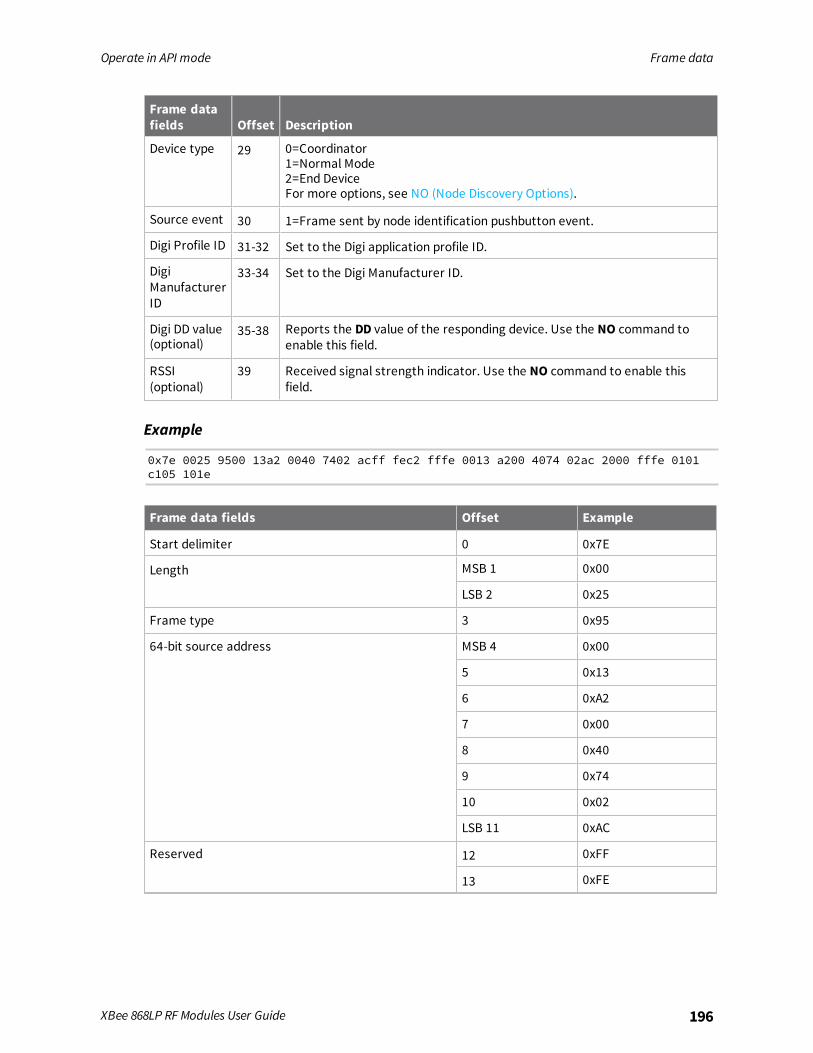
Operate in API mode Frame data
XBee 868LP RF Modules User Guide 196
Frame datafields Offset Description
Device type 29 0=Coordinator1=Normal Mode2=End DeviceFor more options, see NO (Node Discovery Options).
Source event 30 1=Frame sent by node identification pushbutton event.
Digi Profile ID 31-32 Set to the Digi application profile ID.
DigiManufacturerID
33-34 Set to the Digi Manufacturer ID.
Digi DD value(optional)
35-38 Reports the DD value of the responding device. Use the NO command toenable this field.
RSSI(optional)
39 Received signal strength indicator. Use the NO command to enable thisfield.
Example
0x7e 0025 9500 13a2 0040 7402 acff fec2 fffe 0013 a200 4074 02ac 2000 fffe 0101c105 101e
Frame data fields Offset Example
Start delimiter 0 0x7E
Length MSB 1 0x00
LSB 2 0x25
Frame type 3 0x95
64-bit source address MSB 4 0x00
5 0x13
6 0xA2
7 0x00
8 0x40
9 0x74
10 0x02
LSB 11 0xAC
Reserved 12 0xFF
13 0xFE
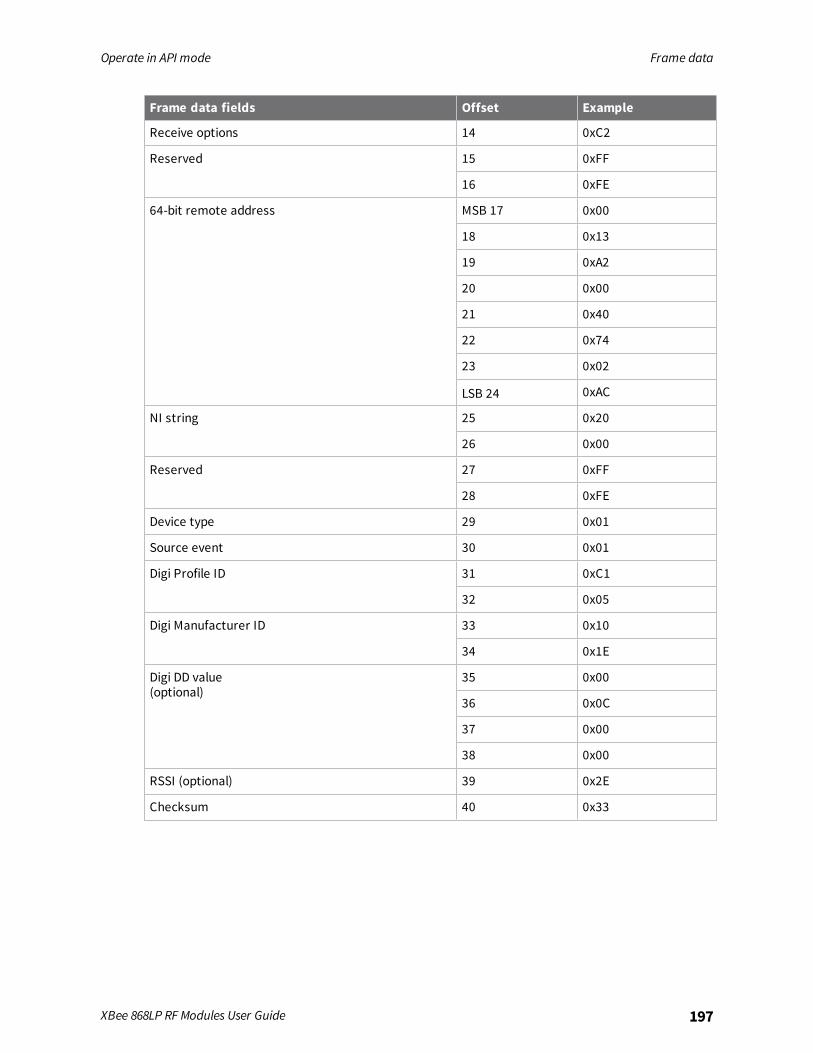
Operate in API mode Frame data
XBee 868LP RF Modules User Guide 197
Frame data fields Offset Example
Receive options 14 0xC2
Reserved 15 0xFF
16 0xFE
64-bit remote address MSB 17 0x00
18 0x13
19 0xA2
20 0x00
21 0x40
22 0x74
23 0x02
LSB 24 0xAC
NI string 25 0x20
26 0x00
Reserved 27 0xFF
28 0xFE
Device type 29 0x01
Source event 30 0x01
Digi Profile ID 31 0xC1
32 0x05
Digi Manufacturer ID 33 0x10
34 0x1E
Digi DD value(optional)
35 0x00
36 0x0C
37 0x00
38 0x00
RSSI (optional) 39 0x2E
Checksum 40 0x33

Operate in API mode Frame data
XBee 868LP RF Modules User Guide 198
Remote Command Response frame - 0x97
DescriptionIf a device receives this frame in response to a Remote Command Request (0x17) frame, the devicesends an AT Command Response (0x97) frame out the serial interface.Some commands, such as the ND command, may send back multiple frames. For details on thebehavior of ND, see ND (Network Discover).
FormatThe following table provides the contents of the frame. For details on frame structure, see API frameformat.
Frame datafields Offset Description
Frame type 3 0x97
Frame ID 4 This is the same value passed in to the request. If Frame ID = 0 in theassociated request frame the device does not deliver a response frame.
64-bit source(remote)address
5-12 The address of the remote device returning this response.
Reserved 13-14 Reserved.
AT commands 15-16 The name of the command.
Commandstatus
17 0 = OK1 = ERROR2 = Invalid Command3 = Invalid ParameterThe most significant nibble is a bit field as follows:0x40 = The RSSI field is invalid and should be ignored.0x80 = Response is a remote command
Command data 18-n The value of the requested register.
ExampleIf a device sends a remote command to a remote device with 64-bit address 0x0013A200 40522BAA toquery the SL command, and if the frame ID = 0x55, the response would look like the followingexample.
Frame data fields Offset Example
Start delimiter 0 0x7E
Length MSB 1 0x00
LSB 2 0x13
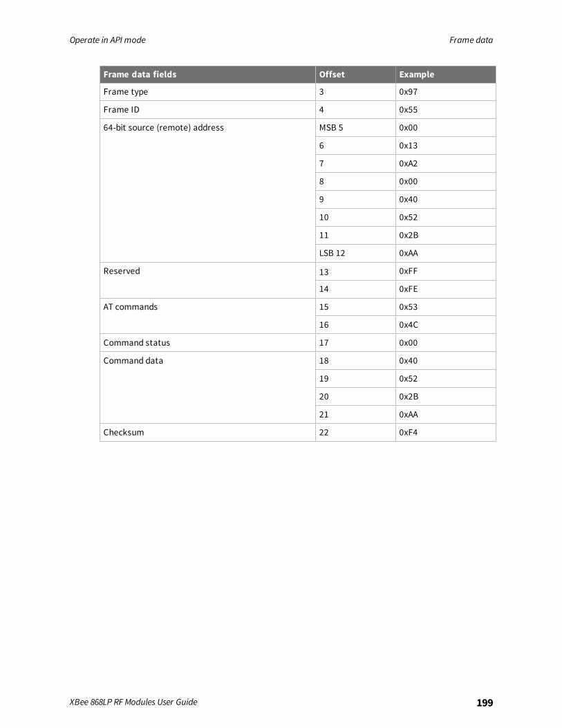
Operate in API mode Frame data
XBee 868LP RF Modules User Guide 199
Frame data fields Offset Example
Frame type 3 0x97
Frame ID 4 0x55
64-bit source (remote) address MSB 5 0x00
6 0x13
7 0xA2
8 0x00
9 0x40
10 0x52
11 0x2B
LSB 12 0xAA
Reserved 13 0xFF
14 0xFE
AT commands 15 0x53
16 0x4C
Command status 17 0x00
Command data 18 0x40
19 0x52
20 0x2B
21 0xAA
Checksum 22 0xF4
Regulatory information
Europe 201Antennas 203
XBee 868LP RF Modules User Guide 200
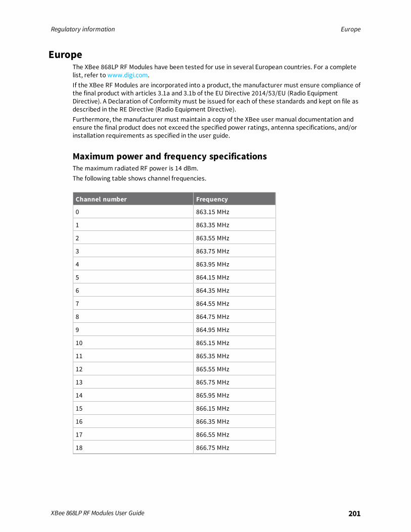
Regulatory information Europe
XBee 868LP RF Modules User Guide 201
EuropeThe XBee 868LP RF Modules have been tested for use in several European countries. For a completelist, refer to www.digi.com.If the XBee RF Modules are incorporated into a product, the manufacturer must ensure compliance ofthe final product with articles 3.1a and 3.1b of the EU Directive 2014/53/EU (Radio EquipmentDirective). A Declaration of Conformity must be issued for each of these standards and kept on file asdescribed in the RE Directive (Radio Equipment Directive).Furthermore, the manufacturer must maintain a copy of the XBee user manual documentation andensure the final product does not exceed the specified power ratings, antenna specifications, and/orinstallation requirements as specified in the user guide.
Maximum power and frequency specificationsThe maximum radiated RF power is 14 dBm.The following table shows channel frequencies.
Channel number Frequency
0 863.15 MHz
1 863.35 MHz
2 863.55 MHz
3 863.75 MHz
4 863.95 MHz
5 864.15 MHz
6 864.35 MHz
7 864.55 MHz
8 864.75 MHz
9 864.95 MHz
10 865.15 MHz
11 865.35 MHz
12 865.55 MHz
13 865.75 MHz
14 865.95 MHz
15 866.15 MHz
16 866.35 MHz
17 866.55 MHz
18 866.75 MHz

Regulatory information Europe
XBee 868LP RF Modules User Guide 202
Channel number Frequency
19 866.95 MHz
20 867.15 MHz
21 867.35 MHz
22 867.55 MHz
23 867.75 MHz
24 867.95 MHz
25 868.15 MHz
26 868.35 MHz
27 868.85 MHz
28 869.05 MHz
29 869.85 MHz
OEM labeling requirementsThe “CE” marking must be affixed to a visible location on the OEM product. The following figure showsCE labeling requirements.
The CE mark shall consist of the initials “CE” taking the following form:n If the CE marking is reduced or enlarged, the proportions given in the above graduated
drawing must be respected.
n The CE marking must have a height of at least 5 mm except where this is not possible onaccount of the nature of the apparatus.
n The CE marking must be affixed visibly, legibly, and indelibly.
Regulatory information Antennas
XBee 868LP RF Modules User Guide 203
Important noteDigi customers assume full responsibility for learning andmeeting the required guidelines for eachcountry in their distribution market. Refer to the radio regulatory agency in the desired countries ofoperation for more information.
Declarations of conformityDigi has issued Declarations of Conformity for the XBee RF Modules concerning emissions, EMC, andsafety. For more information, see www.digi.com/resources/certifications.
AntennasThe following antennas have been tested and approved for use with the XBee 868LP RF Module:All antenna part numbers followed by an asterisk (*) are not available from Digi. Consult with anantenna manufacturer for an equivalent option.
n Dipole (2.1 dBi), Digi PN A08-HABUF-P5I*
n PCB Antenna (-9 dBi), included with the module

Migrate from XBee through-hole to surface-mountdevices
We design the XBee surface-mount and through-hole devices to be compatible with each other andoffer the same basic feature set. The surface-mount form factor has more I/O pins. Because the XBeedevice was originally offered in only the through-hole form factor, we offer this section to help youmigrate from the through-hole to the surface-mount form factor.
Pin mapping 205Mounting 206
XBee 868LP RF Modules User Guide 204
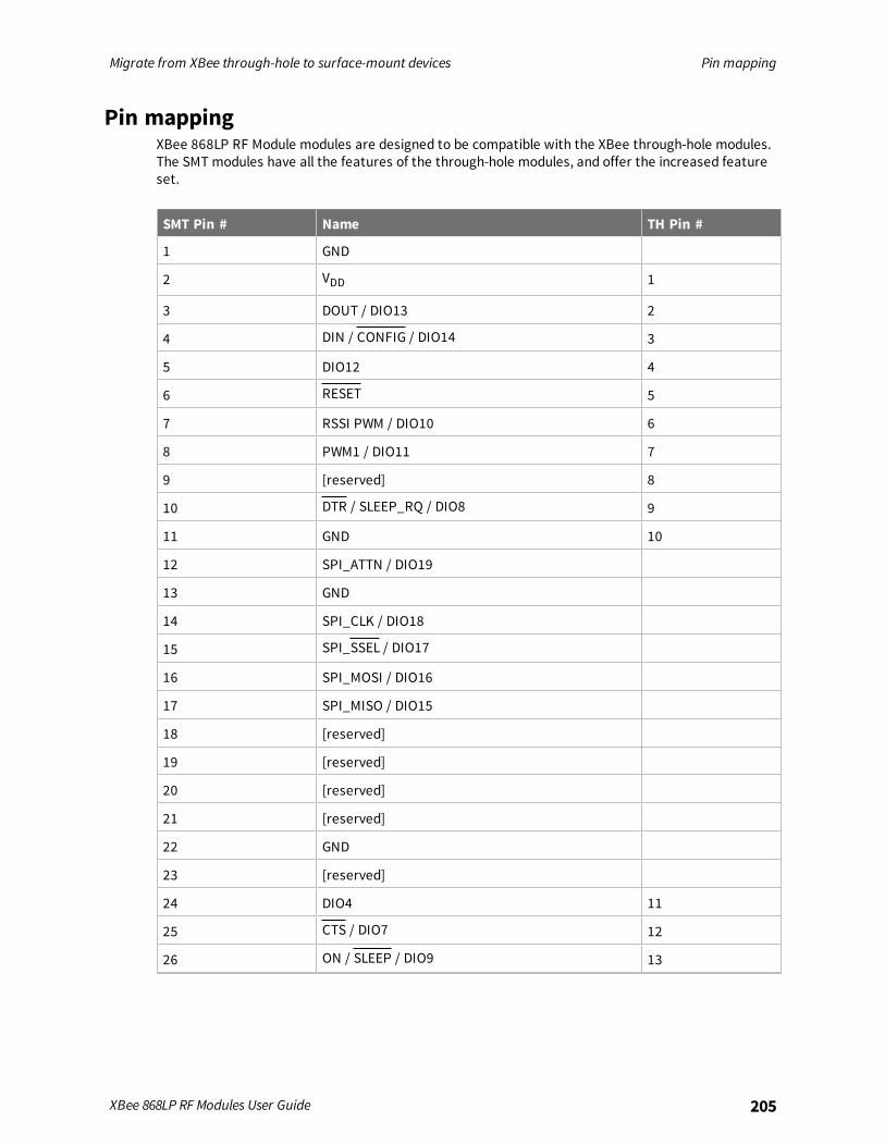
Migrate from XBee through-hole to surface-mount devices Pin mapping
XBee 868LP RF Modules User Guide 205
Pin mappingXBee 868LP RF Module modules are designed to be compatible with the XBee through-hole modules.The SMT modules have all the features of the through-hole modules, and offer the increased featureset.
SMT Pin # Name TH Pin #
1 GND
2 VDD 1
3 DOUT / DIO13 2
4 DIN / CONFIG / DIO14 3
5 DIO12 4
6 RESET 5
7 RSSI PWM / DIO10 6
8 PWM1 / DIO11 7
9 [reserved] 8
10 DTR / SLEEP_RQ / DIO8 9
11 GND 10
12 SPI_ATTN / DIO19
13 GND
14 SPI_CLK / DIO18
15 SPI_SSEL / DIO17
16 SPI_MOSI / DIO16
17 SPI_MISO / DIO15
18 [reserved]
19 [reserved]
20 [reserved]
21 [reserved]
22 GND
23 [reserved]
24 DIO4 11
25 CTS / DIO7 12
26 ON / SLEEP / DIO9 13
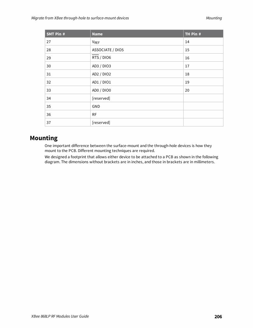
Migrate from XBee through-hole to surface-mount devices Mounting
XBee 868LP RF Modules User Guide 206
SMT Pin # Name TH Pin #
27 VREF 14
28 ASSOCIATE / DIO5 15
29 RTS / DIO6 16
30 AD3 / DIO3 17
31 AD2 / DIO2 18
32 AD1 / DIO1 19
33 AD0 / DIO0 20
34 [reserved]
35 GND
36 RF
37 [reserved]
MountingOne important difference between the surface-mount and the through-hole devices is how theymount to the PCB. Different mounting techniques are required.We designed a footprint that allows either device to be attached to a PCB as shown in the followingdiagram. The dimensions without brackets are in inches, and those in brackets are in millimeters.
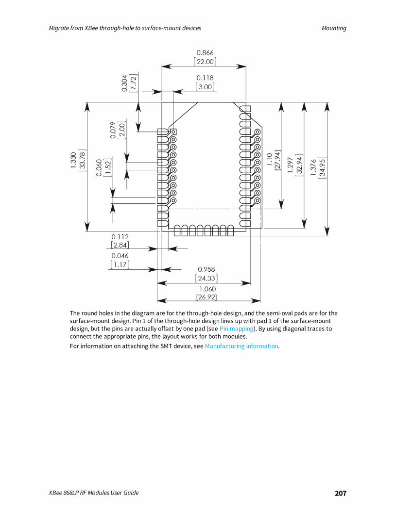
Migrate from XBee through-hole to surface-mount devices Mounting
XBee 868LP RF Modules User Guide 207
The round holes in the diagram are for the through-hole design, and the semi-oval pads are for thesurface-mount design. Pin 1 of the through-hole design lines up with pad 1 of the surface-mountdesign, but the pins are actually offset by one pad (see Pin mapping). By using diagonal traces toconnect the appropriate pins, the layout works for both modules.For information on attaching the SMT device, see Manufacturing information.

Manufacturing information
The surface-mount XBee 868LP RF Module is designed for surface-mount on the OEM PCB. It hascastellated pads to allow for easy solder attach inspection. The pads are all located on the edge of thedevice so there are no hidden solder joints on these devices.
Recommended solder reflow cycle 209Recommended footprint 209Flux and cleaning 211Reworking 211
XBee 868LP RF Modules User Guide 208
Manufacturing information Recommended solder reflow cycle
XBee 868LP RF Modules User Guide 209
Recommended solder reflow cycleThe following table lists the recommended solder reflow cycle. The chart shows the temperaturesetting and the time to reach the temperature.
Time (seconds) Temperature (°C)
30 65
60 100
90 135
120 160
150 195
180 240
210 260
The maximum temperature should not exceed 260 °C.The device reflows during this cycle, andmust not be reflowed upside down. Be careful not to jar thedevice while the solder is molten, as parts inside the device can be removed from their requiredlocations.Hand soldering is possible and should be done in accordance with approved standards.
Recommended footprintWe recommend that you use the following PCB footprint for surface-mounting. The dimensionswithout brackets are in inches, and those in brackets are in millimeters.
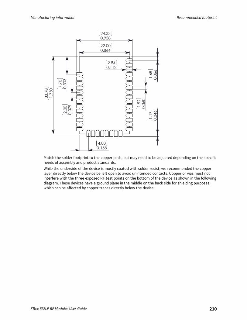
Manufacturing information Recommended footprint
XBee 868LP RF Modules User Guide 210
Match the solder footprint to the copper pads, but may need to be adjusted depending on the specificneeds of assembly and product standards.While the underside of the device is mostly coated with solder resist, we recommended the copperlayer directly below the device be left open to avoid unintended contacts. Copper or vias must notinterfere with the three exposed RF test points on the bottom of the device as shown in the followingdiagram. These devices have a ground plane in the middle on the back side for shielding purposes,which can be affected by copper traces directly below the device.
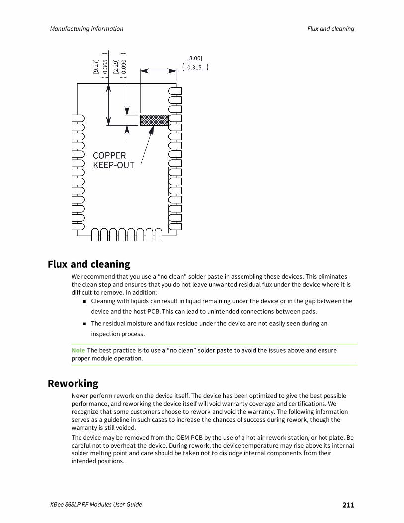
Manufacturing information Flux and cleaning
XBee 868LP RF Modules User Guide 211
Flux and cleaningWe recommend that you use a “no clean” solder paste in assembling these devices. This eliminatesthe clean step and ensures that you do not leave unwanted residual flux under the device where it isdifficult to remove. In addition:
n Cleaning with liquids can result in liquid remaining under the device or in the gap between thedevice and the host PCB. This can lead to unintended connections between pads.
n The residual moisture and flux residue under the device are not easily seen during aninspection process.
Note The best practice is to use a “no clean” solder paste to avoid the issues above and ensureproper module operation.
ReworkingNever perform rework on the device itself. The device has been optimized to give the best possibleperformance, and reworking the device itself will void warranty coverage and certifications. Werecognize that some customers choose to rework and void the warranty. The following informationserves as a guideline in such cases to increase the chances of success during rework, though thewarranty is still voided.The device may be removed from the OEM PCB by the use of a hot air rework station, or hot plate. Becareful not to overheat the device. During rework, the device temperature may rise above its internalsolder melting point and care should be taken not to dislodge internal components from theirintended positions.
Recommended