5q> >^ s
^ s UJ OFFICE OF NAVAL RESEARCH
*• XH Contract NSori 07841
4o
C3 bo
TECHNICAL REPORT NO. 4 September 30, 1953
Metal Processing Division
Department of Metallurgy
Massachusetts Institute of Technology
Cambridge, Massachusetts

OFFICE OF NAVAL RESEARCH
Contract NSori-07841
Project No. NR 031-356
Technical Report Mo* 4
September 30, 1953
i;u_ Jujillc r.-trtoiuiu". Or i.iLi.'iLo
Mechanical Anisotropy in SAE 4340 Steel
by
Davis S. Fields, Jr.
Welter A. Backofc-n
John Wuiff
Metals Processing Division
D.i'O^rtnG.nt of i.letalluro*'
Massachusetts Institute of Technology Cambridge, Massachusetts

m 1
DISTRIBUTION LIST
Technical arid Summary Reports
uontract N5ori-Q7841
Chief of Naval Research Department of the Navy Washington 25, D. C. Attn: Code 423 (2)
Commanding Officer Office of Naval Research Branch Office 495 Summer Street Boston 10, Massachusetts (2)
Commanding Officer Office of Naval Research 3ranch Office 50 Church Street New York 7, New York (1}
Commanding Officer Office of Naval Research Branch Office C44 N. Rush Street Chicago 11, Illinois (l)
Commanding Officer Office of Naval Research Branch Office 801 Donahue Street San Francisco 25,.-Calif*, (l)
Commanding Officer Office of Naval Research Branch Office 1030 Green Street Pasadena, California
Project MR 031-356
Director. Waval Research Laboratory Washington, 25, D. C. Attn: f ;v',. Information Officer (6)
Dr. R. F. riehl Carnegie Institute of Technology Metals Research Laboratory Schenley Park Pittsburgh 13, Pennsylvania
(1)
Assistant Naval Attache fop Rs'^os^c^*
U.S. Navy FJPO #100 New York, New York (1)
Dr. W. M, Baldwin Case Institute of Technology Metals Research Laboratory Cleveland 6, Ohio
Dr. W. C. Craig Armour Kieseai - K E>/v i **v ndation TechnoTOyy Center Chicago 16, Illinois
Dr.-R.- M. Brick Uriversi^ -^ ^siSisylvania Philadelphia^- * .^nsyj va-nia
Dr. Robert Maddin y Johns Hopkin^l^'-. •.." ^ 1315 St." Pat% r;i'Oei?y>' Baltimore 2,;'-•., aryland
Dr. T. A. Read C o 1 umb i a Un i ve r s i t y Mew York, Few York
Dr. Es P_s Klier University of Maryland College Park, Maryland
T~\ '- f» ft T*> t uxi ft "j..DecK University of Notre Dame Notre Dame, Indiana
Dr. E. P. Parker University of California Berkeley 4, California
(1)
(1)
(1)
(1)
(1)
(1)
(1)
(1)

SSSKSi^S--- Ss — -- — "•
Director, Naval Research Laboratory Washington 25, D. C. Attn: Code 3500, Metallurgy Div.s (l)
Code 2020, Tech. Library " (l) Code 3G0C, Mechanics Div. (l)
Bureau of Aeronautics Department of tne Navy Washington 25, D. C, Attn; N. E. Promisel, AE-41
Technical Library, TD-41 (3) (1)
I
Command in ••- Officer Naval Air Materiel Center Naval Base Station Philadelphia, Pa.
Attn: Aeronautical Materials Lab. (l)
Bureau of Ordnance Department of the Navy Washington 25, D. C. Attn: Rex
Technical Library, Ad3
Superintendent, Naval Gun. Factory Washington 20, D. C. Attn: Metallurgical Lab., i:'910
(3) (1)
Commanding Officer U.S, Naval Ordnance Laboratory White Oaks, Maryland
(1)
(1)
NAVY
Bureau of Yards and Docks Department of the Navy Washington 25, D. C. Attn: Research & Standards
Division (l)
Post Graduate School U.S. Naval Academy Annapolis, Maryland Attn: Dept. of Metallurgy (l)
ARMY
Chief of Staff, U.S. Army The Pentagon Washington 25, D. C, Attn: Director of Research
and Development (l)
Office of the Chief of Ordnance Research and Development Service Department of the Army Washington 25, D. C, Attn: ORDTB (3)
Commanding Officer Watertown Arsenal
Commanding Officer U.S. Naval Ordnance Test Station Inyokern, California
Bureau._ of1S hips Department of the Navy Washington 25. D.C. Attni Code 343
Code 337L, Tech. Library
U.S. Naval Engineering Experiment Station Annapolis, Maryland Attn: Metals Laboratory
Director, Materials Laboratory Building 291 New York Naval Shipyard Brooklyn 1, Mew York Attns Code 907
(1)
(3) (1)
(1)
(1)
Watertown, Massachusetts Attn: Laboratory Division (l)
Office of the Chief of Engineers Department of the Army Washington 25, D. C. Attn: Research and Development
Branch (l)
U. S. Air Force Research S Development Division The Pentagon Washington 25, D. C. (l)
Air Materiel Command Wright-Patterson Air Force Base
_Daytojl. Ohio Attn: Materials Lab.- MCREXM (2)
Office of Air Research Wright Field Dayton, Ohio Attn: Metallurgy Division (l)
iii.
DISTRIBUTION LIST - Technical and Summary Reports ~ Continued Contract N5ori-07841 Project NR 031-356
OTHER GOVERNMENT AGENCIES
Atomic Energy Commission Division of Research Metallurgical Branch Washington 25, D. C. (l)
National Bureau of Standards Washington 25, D. C. Attns Physical Metallurgy Div. (1)
National Advisory Committee for Aernonautics 1724 F Street, N. W. Washington 25, D. C. (1)
Research and Development Board Committee on Basic Physical Sciences The Pentagon Washington 25, D. C. Attn: Metallurgy Panel (l)
U. S atomic Energy Commission 1901 Constitution Aye., N. Y. Attn: B. M. Fry (2)
Armed Services Technical Information Agency Documents Service Center Knott Building Dayton 2, Ohio (5)
Office of Technical Services Department of Commerce Washington 25, D. C. (1)

DISTRIBUTION LIST IV.
i^miDuiiuN LIST - Technical and Summary Reports — Continued ontract N5 ori-07841 Project N8 031-356
K i
Argonne National Laboratory P.O. Box 5207 Chicago 80, Illinois Attn: Dr. Hoylande D. Young (l)
Brookhaven National Laboratory Information and Publication Division Documents Section Uptom, New York Attn: Miss Mary E» Waisman
(i)
Carbide and Carbon Chemicals Div. Plant Records Dep rt.me.nt Central Files (fc- .5) P.O. Box P Oak Ridge, Tennessee
Carbide and Carbon Chemicals Div. Central Reports and Information Office (-12) P.O. Box P Oak Ridge, Tennessee
General Electric Company Technical Services Division Technical Information Group P.O. Box 100 Richland, Washington —- AtfnT Miss M. G. Freidank
(1)
(1)
Iowa State College P.O. Box 14A, Station A Ames, Iowa Attn: Dr. F. H. Spedding
Knolls Atomic Power Laboratory P.O. Box 1072 Schenectady, New York Attn: Document Librarian
Los Alamos Scientific Laboratory P. 0. Box 1663 y
Los Alamos, New Mexico d4-4.,-.. n_ . ,-, "t.t.i. i^uoumcnL custodian
(1)
(1)
(1)
(1)
Mound Laboratory V. S. Atomic Energy Commission P. 0. Box 32 Miamisburg, Ohio Attn: Dr. M. M. Haring (l)
U.S. Atomic Energy Commission New York Operations Office P. 0. Box 30, Ansonia Station New York 23, New York Attn: Div, of Technical Informa- tion and Declassitication Serv. (i)
Oak Ridge National Laboratory P. 0. Box P Oak Ridge, Tennessee Attn: Central Files
Sandia Corporation Sandia Base Classified Document Division Albuquerque, New Mexico Attn: Mr. Dale N. Evans
(1)
(1)
U.S. Atonic Energy Commission Library Branch, Tech. Information Service, ORE P.O. Box E Oak_Ridge, Tennessee (l)
T r— i . University of California Radiation Laboratory Information Division Room 128, Building 50 Berkeley, California Attn: Dr. R. K. Wakerling (1)
Westinghouse Electric Corporation Atomic Power Division P.O, Box 1468 Pittsburgh 30, Pennsylvania Attn: Librarian (n
ir*?.

DISTRIBUTION LIST - Technical and S r__x -.- - - m 031-356 Contract N5 ori-0784l""""Soject""^-ar?-Reports - Continued
v.
Dr. John Dorn llnivprei t\> r-c ^.ltr .w • v ix.r WJ. <--aAifornia Berkeley 4, California
Dr. Pol Duwez California Institute of Techno]0qy Pasadena 4, California
Dr. D. S. Clark California Institute of Technoloov Pasadena 4, California
Dr. N. M. Newmark University of Illinois Urbana, Illinois -
Dr. T. J. Dolan University of Illinois Urbana, Illinois
Dr. H. Eyring University of Utah Salt Lake City, Utah
Dr. Finn Johassen National Academy of Sciences 2101 Constitution Avenue Washington 25, D. C.
Dr. Max Gensaruer — - -•' Columbia University New York, N, Tr
Prof. C. W. Macgregor University of Pennsylvania Philadelphia, Pennsylvania
Dr. W. H. Hibbard General Electric Company Schenectady, Mew York
Prof, C S* Smith Institute for Study of Metals University of Chicago Chicago, Illinois
Prof. Amos J. Shaler The Pennsylvania State College State College, Pennsylvania
(1)
(1)
(1)
(1)
(1)
(1)
(1)
(1)
(1)
(1)
(1)
11 \
Dr. J. H. Hollomon General Electric Company Schenectady, New York (1)
Dr. P. Coheur Centre National de Recherches
Metallurgiques Liege, Belgium Via: Assistant Naval Attache for
Research U.S, Navy FPO 100 New York, N. Y. (1)
Prof. Mott University of Bristol Royal Fork Bristol 8, England Via: Assistant Naval Attache
for Research U.S. N \vy FPO lbe New York, N. Y.
Dr. C. F. Tipper Department of Engineering Cambridge University, England Via: Assistant Naval Attache
for Research
(1)
U.S. «avy FPO 100 New York, N, Y.
(1)
Prof. E# Orowan Department of Mechanical Engineering Ma? s. Inst. of Technology Cambridge 39, Massachusetts (l)
Prof. H. IV. Swift Department of Engineering ~ Sheffield University. England Via: Assistant Naval Attache
for Research U.S. Navy
-FPO 100 ~ Mewr York, N. Y. (l)
Dr. J. T. Ransom-. Materials of Construction Section E. I. du Pont de Nemours & Co, Wilmington, Delaware (l)
ABSTRACT
K
I I
The tensile fracture characteristics after various amounts of torsional prestrain have been studied in specimens of SAF 4340 steei of three grades: vacuum- melted, aircraft quality, and commercial quality. The presence of a submicroscopic crack structure is indi- cated in all three grades by the transition from high to iow values of tensile fracture stress and strain-to- fracture, after critical amounts of prestrain in torsion. The vacuum-melted steel, which is practically inclusion- free, is affected somewhat more-by twisting; in particu- lar, the critical prestrain value is lower. The commer- cial and aircraft grades, however, are practically identical in their response to prestraining. It .-jop^ars, therefore, that inclusions are not the principal St, ret of microcracks in the materials tested, and that static transverse properties are not greatly influenced by inclusion content, within the range encountered in this work. Since there is a marked difference in grain size between the commercial and aircraft quality steels, it is also concluded that prior austenitic grain size is not a primary factor in the behavior studied. Certain systematic scatter In the data is explained on the basis of oriented microcracks.
INTRODUCTION
The anisotropy in fracture characteristics* of many wrought
materials has been studied. Wells, Mehl, and their co-workers,1'2'3
in particular, have made extensive statistical comparisons of the longi-
tudinal and transverse tenslie.properties of forged low alloy steel.
Figure 1 shows that the reduction in area at fracture varies with the
* Tensile fracture characteristics-considered are strain-to-fracture, expressed as a percent reduction in area, and the average true stress at fracture.

2.
o * u to m
>.-< a> +» ^ sz -4 Q> 'Ji ^S ^ •H +> +• » C O 0) 0> 3 J3 -* QO«
JC 3 •tJ g !T - P "J CMC O «H
3 "S O *
+» +> to «l u « 0 3 U>
•P O «*-< w « OCX)
O fl^ »» t» -A« .-« a> e "^ o>oe « c-
«•-• a> i*"*^ o a> $ »t •Pino fe o » C>lf) H " s* 3 £. X <+* O 0 c Ul ^ S »W
I)
3dniovyj
r^

3.
angle of test; it is a maximum in the flow (forging) direction, and a
minimum in the transverse direction. Among other workers in this field,
4 Jacquesson and Laurent have observed that the fatigue strength of rolled,
high purity aluminum decreases with the angle of test in a somewhat
similar manner. The tensile fracture characteristics of hot-rolled plate
of the aluminum alloy, 24ST, also have been shown""' to be greater along
and near the rolling direction.
Prompted by the work of Griffith0 on truly brittle materials,
7 it has been suggested that cracks of submicroscopic size may be present
in ductile metals. They would very likely be elongated during plastic
deformation, and certainly aligned parallel to the direction of metal
flow. Ductility and fracture stress should then be lowest when tension
is applied in a direction perpendicular to these cracks.
Swift- observed that the fracture characteristics of mild
steel tested in tension decrease sharply when specimens are first twisted
to a surface shear strain of approximately unity. Simultaneously the_
ductile, cup-and-cone type of fracture is replaced by a helical, "wolf-
eared" one. Specimens twisted and completely untwisted before testing
retain their original fracture properties and mode of failure.
o Recent work by Backofen and Hundy,'/ and also by Backofen, Shaler,
and Hundy, has demonstrated this behavior in OFHC copper, 70-30 brass,
nickel, Monel metal, Armca iron, and high purity (99.99>o) aluminum. Com-
mercially pure (2S) aluminum was the only material tested which did not

4.
respond to prestraining in the described fashion,
The effect is explained in terms of aligned microcracks. In a
bar which has been heavily reduced by rolling, forging, swaging, etc., all
of the cracks will be aligned parallel to the direction of elongations
During twisting of a specimen talcen parallel to this direction, the cracks
will be realigned at-an angle $ to the specimen axis, so that
where r. is the distance of the crack from the specimen axis, © is the
total angle of twist in radians, and 1. is the length of the specimen in
which twisting occurs; jjf defines the shear strain at the radius £ from
the specimen axis and it varies linearly from zero at the center to its
maximum value at the surface of the bar. In an untwisted bar, $ will
be zero, and tension on the specimen, before necking occurs, applies no
aormal stress to the cracks-*- After 3 critical amount ef: twisting, ft
becomes sufficiently large that stresses acting on the cracks can cause
failure through their extension. Untwisting a twisted specimen before
testing realigns the cracks parallel to the bar axis where they have a
minimum of influence upon fractvire characteristics.
9 10 It was further observed * that the angle of fracture in
twisted specimens was verv close to the calculated angle, ft. Neither
this observation nor that of the restoration of ductility by untwisting
can be suitably explained by theories not. based upon aligned defects in
the metal.

5.
Tho nature of microcrackc- is still unclear. They may be in-
herent in the casting. On the other hand, in ductile metals they may be
generated by the deformation itself; »2 brittle phases in the micro-
structure, such as cementite plates in steel, may be fractured as the
ductile matrix-material deforms. A local accumulation of dislocations
could be considered to form a microcrack. Yet discontinuities due to non-
metallic inclusions and other extra phases in the microstructure are the
only observable "flaws" in otherwise sound metal which might account for
the measured anisotropy.
Very striking evidence that inclusions contribute to anisotropy
has just been reported by Ransom,13 who found that the transverse fatigue
strength of vacuum-'melted, essentially inclusion-free SAE 4340 steel aver-
aged fifty percent higher than the same property of commercial SAE 4340.
He showed that fatigue cracks propogate from the edges of elongated inclu-
sions when they are acted upon either by a principal tensile stress or a
maximum shear stress. However, even in the vacuum-melted steel the ratio
of transverse to longitudinal fatigue strength was only 0,86. This shows
that even when the inclusion content is practically nil, there is still a
fibrcjs structure producing anisotropic properties. Banding was a problem
in the ultra-clean steel, and might contribute to this fatigue strength
ratio of less than one; but the contribution from a highly oriented crack
structure has not been ruled out.
In the past, much consideration has been given to the possibility
L

6.
of controlling transverse properties in wrouoht steel through control cf
the size, shape, and distribution of non-metallic inclusions. The pre-
sence of a highly oriented crack structure suggests that there might be
a limit to vvhHt car. bo accomplished with such control. Therefore it was
the purpose of this research to determine the tensile fracture character-
istics of SAE 4340 steel of three degrees of cleanliness after prestrain-
ing in torsion; and, in this way, ta study relationships between anisotropy
in fracture characteristics, the crack structure, and inclusion content.
EXPERIMENTAL PROCEDURES
Materials and Processing
Chemical analyses of the three steels tested arc summarized in
Table I. -Those of aircraft and commercial quality were from regular heats
of SAE 4340 steel. The vacuum-molted sample was from an experimental heat
described by Ransom.13 It varies from the nominal SAE 4340 composition
principally in the absence of phosphorous, sulphur, and retained gases.
[I
;

n
If
TABLE I
It
M?lYSeg Of Sy.^ (Prrcont by W?1l^)
Vacuum- Melted
Aircraft Quality
Commercial Qualitv
It;
Carbon Manganese Phosphorous Sulphur Silicon Nickel Chromium .-.ox t^ «unuiii Vanadium Nitrogen Oxygen
Producer National Re- search Corp.
0.39 0.69
0,41 0.75
0.41 O.CO
nil 0.009 0.033 nil 0.014 0.019 0.37 0.31 0.2S
1.78 1.79 1.72 0.97 0.C4 0.62 U. JJ. 0.26 0.24 0.13 nil _aiL — 2,5 x 10~4 A », 1 /\— ."iJi . .--a.
**s *-' A XV — »< D X J.0 ~* lib X 10--3
6 x 10" 3* S x 10-3*
Keat No.
•Nominal values from
United States United States Steel Corp. Steel Corp,
9X5510 9X5778
ASM .Metals Handbook
____ Materials ware received ^rom-suppliers as two'ancTorie-half inch
diameter, hot-forged rounds approximately one foot long. Each sample was
hot-swaged above 1800°F to seven-eighths inch diameter. The bars were
then cut into blanks two and one-half inches long, and the vacuum-melted
samples were subjected to a twenty-four hour homogenizing treatment at
19C0°F. Subsequently all specimens were heat treated by normalizing one
hour at 1700°F, austenltizing two hours at i600°Fj oil quenching, tempering
four hours at 1200'"'f, water quenching, re-tempering two hours at 1200°F,
and water quenching. The vacuum-melted steel was quite sluggish in its
response to tempering; it was necessary to re-temper many of these specimens,

and also a few from the other lots, for additional periods at 120C°F in
order to bring their hardnesses down to a common level.
The heat-treated blanks wore machined into torsion specimens.
Following two-hour stress relief anneals at 10S0°F before and after
finish machining, they were polished through 00C0 ornery paper. Specimens
were then twisted, machined for tension testing, and again polished
through 0000 emery. Dimensions of test bars are shown in Figure 2.
Testing Procedures
The bars were twisted in a torsion testing machine operating
at a constant angular speed of ninety degrees per minute. Autographic
records of torque versus angle of twist were obtained for all specimens.
The. shear strain at the surface of -the tensile specimen v;as calculated"-
for each bar. ^
i
Tension testing was performed on a hydraulic machine operating
jln_a load range from zero to ten thousand pounds. Values of load and
instantaneous minimum bar diameter were determined at frequent intervals L
during each test, from these readings, a curve of average true stress *
versus true strain* could be calculated for each specimen. A single test — ,4
; ^ --J * Definitions of terms: ii
True stress - the instantaneous load divided by the instantaneous J minimum specimen diameter. \
True strain - 2 ine(d0/d), where d0 is the original and d the "«»"• ? instantaneous specimen diameter. j
Engineering tensile strength - the maximum load dividpH by the original M
area of the specimen. A
\ j

s
3
•
UJ
o LLI n CO
(/)
o (/)
UJ
1 O LU CL CO
h-
LU
O CO cr o
ro
-i*»
/
"o m
-I*
± ib|oo
0) c
u &
in
3 O 0) c
i .1
.5
f

10.
were required approximately twenty minutes to perform. Strain rates
sufficiently low that accurate values of fracture stress, maximum reduc-
tion in area, and engineering tensile strength could be determined.
To measure the angles of fracture in specimens failing across
helical surfaces, a light circumfc-rential scratch, normal to the specimen
axis, was inscribed around the broken specimen just below the point where
fracture originated, The angle between this line and the fracture sur-
face was measured with a toolmaker's microscope.
RESULTS OF EXPEHIf.ENTAL WORK
Uniformity of Materials
Every effort was made to insure that the steels would be identi-
cal in every respect except inclusion content. Their histories were essen-
tially identical from forged bars to btDr.witspecimens. The following
observations serve to check the degr&e frpT which"their properties coincide;
f.iicrostructure: Micros tructurc-s of the three steels, at high
magnifications,'are shown in Figure 3j they all consist of tempered marten-
site in the spheroidized condition. In addition, the vacuum-melted steel
contains a small amount (less than ten percent) of tempered bainite, only ',
it partially spheroidized. The photomicrographs of Fiqure 4 were etched to i
show the prior austenitic grain size. The vacuum-melted steel has mixed I
grains, with a majority ojL.4S?M Grain Size Mo. 2. The aircraft and '
commercial quality steels are more regular, having ASTI-i Grain Sizes No. 5
and 10 respectively.

'I?'" l.Af*M
^4CJ«JS— • • -• • ... . - -• - - - .....
*i5-U^! '0^mm!m^wm^m^^m^jm^mi
EifflUBB 3
Microstructures of SAE 4340 Steels: (top to bottom) Vacuum- melted, Aircraft Quality, Commercial Quality; Picral Etch
x500
11.
r
K

io Rf
"3^ta-ar;r^KTT«4k?»i^«f j
Figure <t
Austenitic Grain Sizes of SAE 4340 Steels- (ton +« K«^ \ „ melted, Aircraft OuaHtv r^mZ^.i^V .p to b°tt«»J Vaeuum- , xrurcirT. yuaiity, Commercial Qualityj Vilella Etch

13,
Tension and Ifig§jkffiQ Tests: Figure 5 presents typical true
stress-true strain curves for untwisted bars tested in tension. The
strength levels at a given strain and the strain hardening characteristics
arc quite similar for the three steels. There is a small, reproducible
variation in the reductions-in-area at fracture. For the aircraft quality
steel it was sixty-four percent} for the other two., approximately sixty
percent.
Figure 6 shews typical torque-twist curves recorded autographi-
cally during prestraining. The characteristics of the three steels arc
almost identical in torsion. The only difference to be noted is the
presence of a slight yield point effect in the commercial steel, a less
pronounced one in the aircraft quality, ?.nd none at all in the vacuum-
inelted material.
In the "soft" hydraulic machine used for tension testing it was
to observe: any yield pnint effects."•——""
Hardness: Heat treatment of the specimens was designed to pro-
duce maximum ductility and minimum hardness. Several Rockwell hardness
measurements were made on the ground end of each specimen after final neat
treatment. The average values for all bars are recorded in Table II.

240
IJ in uj K •- </> UJ 3 40 K »-
O VACUUM MELTED A AIRCRAFT D COMMERCIAL
0.2 0 4 0.6 O.B
TRUE STRAIN
1.0
Figure 5
Typical True Stress-True Strain Curves in Tension for Untwisted Specimens
14.
...
2000
1500
a
3 O
j r\Q j
O K O
500
AIRCRAFT
VACUUM MELTED
COMMERCIAL
180 360 -SAn
ANGLE OF TWIST IN DEGREES
Figure fr
Typical Curves of Torque Versus Angle of Twist
^CL:

15.
Table II
Hardness of Spccimuns
Mean Hardness Average Deviation RockweJ.1 "C" from the Mean
Vacuum-melted lb-l/2 1 Aircraft Quality 14-1/2 1 fmrnr*/-! •>! ^i ; T IT +-; 1 G-1 /O 1
Inclusion Content: All three of the- steels are "clean" by com-
mercial standards. The aircraft and commercial grades have approximately
the same density of non-metallic inclusions, with a slight tendency for
some to be elongated in the forging direction. The vacuum-melted steel
has only the smallest of inclusionsj all of them are spherical.
Effect of Torsional Prestrain upon Tensile Properties -
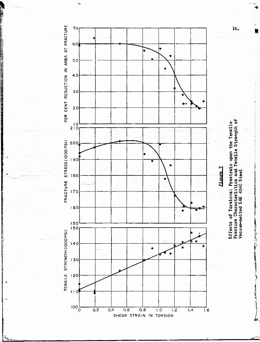
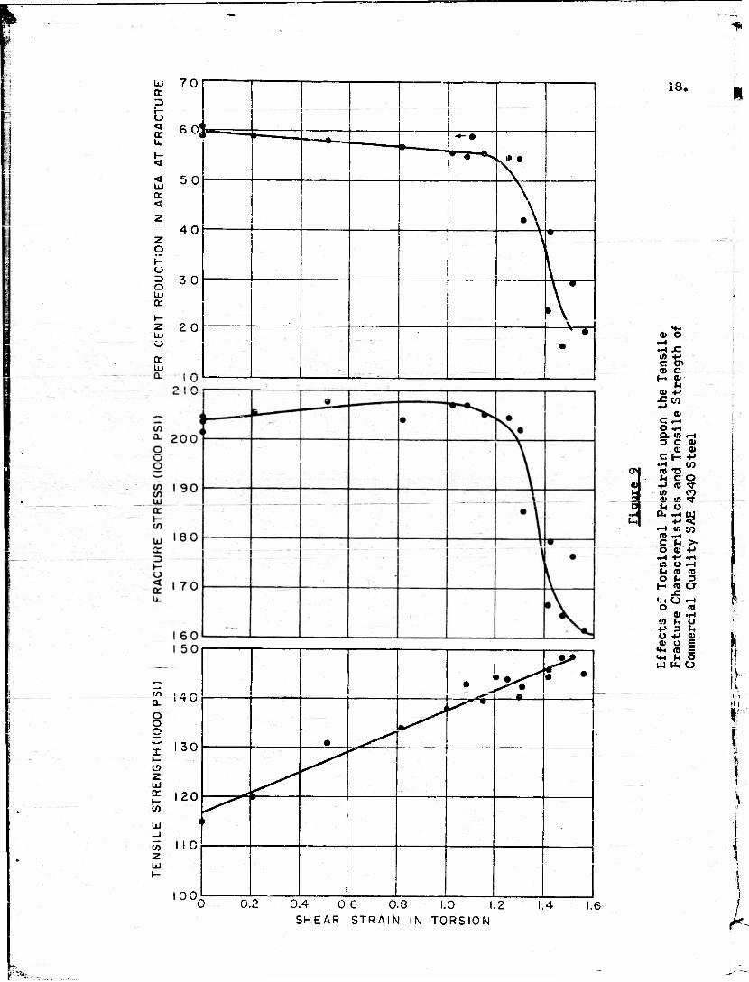
The effects ef prior twisting upon the tensile fracture- charac-
teristics of the vacuum-melted, aircraft quality, and commercial quality
steels arc shown in Figures 7, C, and 9, respectively. All of the test
points are included with those curves. The specimens supported a sizeable
fraction of their maximum loads even after helica? cracks were visible in
their surfaces. Consequently the curves of average true stress versus
true strain in some cases showed a range of strain over which stress re-
mained essentially constant. In this range, elongation occurred both by
plastic deformation and by propagation of the cracks. Fracture stress and
reduction in area values at fracture were chosen as the points at which the
%
tu
o <t tr u.
tr <
o f- o o UJ <r
UJ
UJ a
en a o
i
UJ Q:
co
en 2 UJ
70
60
40
30
20
10 2 I 0
55 200, a. o o o 3 I 90 CO CO UJ cr H CO
_____ —" «•—-. I— __^^
a X t—
• \
(I \
16.
UJ (T
I— O < <r u.
180
ISO
150 150
40
130
20
100
1
1
- — r— ;-
• \
•
• \ •
- -
• Y
>
\ *
-
•
3**^
• . *
• ^. e
a> o •H x: . . - in +» e o> a> c H a>
H ..' 0) +> J=lO +»
0) C ~» O ~4 Q. (0 3 C
0) C H fc- •H .-..
ai «0 T3 »H JH C tt
s >f> +> c a> to c/>
a. £ «-t o +»<tf
_J >A /V\
(0 -J «* CM o a> uj
•H +»< w O CO u to O (4 *o H « 0)
.C +> <*« O rH O Q>
9 S +» 3 g o +> 5 « O 3
<«H (0 O «4H M fl» UJ u, >
0.2 0.4 0.6 0.8 1.0 1.2
SHEAR STRAIN IN TORSION
1.4
h *-yy...^. >- ,...„„

1.1
17.
- 2 10 L_ V— •+—
o 20°
o
• •
• • V I
o o (A
ffl l90 •\
or .
"'""- '--'-_ :-- — \ •
•
UJ 180 or P " ~~
•
\—1 r; — 1 •'
2 170 T
1 60 1 i i —
ool „•
uj
s? c •H £ (0 •»-» C Of o> c
l~. 0)
o» +>
C ^4 O ~4 Q. W 3 C - • ~* t: t-> o>
a* (0 *a ^ c to <o o a» io <* Jh *> <*» Q. i-i *f
•H «o ty
O qj w' •H 4-» >. u> O •*->
O *4 -+ H ffl U
tfO Or o a> +>
+• 3lJ o+> h 0)OO
«*H <0 (4
0.2 0.4 0.6 0.8 1.0 1.2 SHEAR STRAIN IN TORSION
I;
Ul ct p r—
< ce u.
< ui or <
z o
U
Q Ul CC
Ui
O O
I
CO z UJ CC (- to
UJ _j
to z UJ
70
60
50
40
30
20
" '1 "•-•
\
\ \ • •
\ * •
•
18.
130
120
« o
00
1 —. 1 1 .—-+^9\ •
I I f | ^*^i i I
•H JC <0 +* c o» oi e H <U
fH 0 -t-> J= CO •»->
0) C -1 O M-> O. m —t 3 C 0
Q> 0> C H +1
•H LO UJ TJ N CO +> <0 <"!• 10 CO (11 (A «f
u. .H ty -• «to <0 n-4 C (4 >• O «"+*
•(-• +J «(H e UH f-t IB m O M 3 h «a
JC *H O —< i O (0
01 .M at u o +» 3 h o ••-> a> j i a> o I j i
«*•• <TJ g i 5 >4-. u o ] in u. o >
i. i i
iLi
1
0 0.2 0.4 0.6 0.8 1.0 1.2 SHEAR STRAIN IN TORSION
1.4 1.6
rjPfcfc—

19.
true stress-true strain curves deviated from their essentially linear
character.
There is considerable scatter in the data. The curves of engi-
neering tensile strength versus prestrain were plotted as an aid in detec-
ting specimens with atypical strengths which might cause anomalous fracture-
characteristics.
All three steals show an abrupt transition from high to low
values of ductility and fracture stress after critical amounts of prior
twisting. There was little change in either of these properties as speci-
mens were twisted to surface shear strains of approximately one. At that
point, the curves drop sharply. Simultaneously the mode of fracture
changes from the cup-and-cone type to an angular or helical one. At the
maximum shear strain which cculd be introduced into the specimens without
risking failure in torsion, the curves showed only a slight tendency to
approach a constant lower value of cither fracture stress or ductility.
Figure 10 superimposes the fracture characteristic and tensile
strength curves of the three materials for comparison. The tensile
strength values ore consistent with the hardness levels of Table IT, i.e.,
the harder materials possess the higher tensile strengths. The levels of
fracture stress before transition also reflect this difference, the lowest
tensile strength, for example, being associated with the material of high-
est fracture stress.

LU
o:
< a u.
UJ
<
Z g o Q UJ a:
t- z UJ u
UJ a.
to a. o o o
in (/> UJ cr i- t/5
UJ a H O < u.
a. o o o
o z UJ
UJ
z UJ
20.
C
U.
0) »H m •H £ U> +•> C » « C H ?>
u At JU
a» C F-l
G. ID -) 3 c a>
4> 0> C H +»
M £ o +» m •* w en oi w *t
c u<+* o © o ~t 4-> <0 O to h ID V O faT> H «8 <D
r (4 «*«o o o 4) a>
+> 3 M U 4-> JC <U O H
«*- 10
UJ u. o
I
5
0.4 0.6 O.R in i -
SHEAR STRAIN IN TORSION

21.
The critical shear strain is approximately the same for the
aircraft and commercial qualities of steel, and the elopes of the curves in
the region of transition are nearly equal. On the other hand, the fracture-
stress and ductility of the vacuum-melted material begin to fail at a
lower prestrain; and the transition is not so sharp.
There was no obvious difference between the fracture surfaces
of specimens of different quality but having approximately the same frac-
ture strength and ductility. Before transition, fractures were of the cup-
and-cone type originating at the center of the necked specimen. Late in
transition, fractures were completely helical or angular. They originated
in the highly strained specimen surface, and propogatod inward. Between
the two extremes there "was A compromise fracture exhibiting tendencies
towards both types of failure. Cracks evidently propoyate both inward and'
outward in such a case. Figure 11 shows typical fractures in specimens
"twisted to different amounts of prestrain.
No trend was apparent in the angle-of-fracture versus prestrain
data since the -range of prestrain was relatively low. The angles were,
however, close to those of other materials subjected to the same amount of
9 10 prior twisting,-' i. e., somewhat Liryur than the caicjlated angle at
vvhich microcracks would be aligned by twisting. Presumably this is due to
rotation of the microcracks back toward the specimen^axis during deforma-
tion prior to fracture during testing.

21.
Figure 11
Tensile Fractures of Specimens Previously Prestrained in Torsions (left to right, JT = 0, 1.15, 1.48, and 1.50). Approxi- mately twice actual size.
L

23.
DISCUSSION OF EXPERIMENTAL RESULTS
As Figure 10 shows, the tensile fracture characteristics of each
of the three grades of SAE 4340 steel are influenced approximately the sane
way by torsional prestraining. Interpretation of the data requires the
presence of a highly oriented crack structure initially aligned in the
direction of the specimen axis. ' Torsion-tension testing and convention-
al testing to establish the relationship between longitudinal and trans-
verse properties (Figure 1) are similar; therefore- information from the one
kind of testing should be similar to that produced by the other.
The similarity of the results for the three steels is rather
surprising inasmuch as they differed in several respects: cleanliness,
prior austenitic grain size, and chemical composition. A further but pro-
bably insignificant microstructural difference of about ten percent partial-
ly spheroidized bainite existed between the vacuum-melted and the other
two grades.
It would be expected that inclusions in the steel, especially
those aligned normal to the testing direction, would provide points of^
weakness at which failure could begin. Indeed-, in fatigue testing in the
transverse direction, cracks do propogate from the ends of elongated ir.cl.u-
13 sions. However, over the range of inclusion contents studied- and these
are admittedly "clean" steels- they have no significant effect upon the
anisotropy of the statically determined fracture characteristics. The
cleanest steel is, in fact, the most highly anisotropicj and one cannot

24.
possibly consider this to bo due to the absence of inclusions. The re-
sults, then, must be the consequence of a highly oriented crack structure
in all steels. 'Whereas a transverse fatigue- failure occurs after local
damage near the few largest cracks (inclusions) in the specimen, failure
in static testing is not so localized, and must be due to the simultane-
ous growth of many microcracks whose density in the specimens is very high.
A question that still mt 5t be answered is why the vacuum-melted
steel has the greater sensitivity to prestraining. The large prior austen-
itic grain size (Figure 4) can be discounted as the only cause, since the
commercial and aircraft quality steels have identical fracture character-
istics while exhibiting a pronounced difference in grain size. The varia-
tions in chemical composition and in microstructure, except for grain size,
are slight; flow characteristics (Figures 5 and 6) are hardly affected by
them, and it seems logical to draw the same conclusion about the fracture
13 characteristics. Ransom reported that the vacuum-melted steel had
pronounced longitudinal banding as 2-1/2 inch round stock. After the
additional swaging and homogenization heat treatment used in the present
research, only the slightest banding was observable-; again it seems hardly
likely that the variable is a significant one.
The unusual processing history of the ultra-clem steel probably
is most likely responsible for its lower critical shear strain. Both the
special melting practice and the lower amounts of reduction given to the
small cast ingot could have some bearing upon the nature of the crack
structure. —.

25,
Scatter in da1;a
Figure 1 shows not only the variation of reduction in area with
the angle of test in a forged steel, but also the standard deviations of
the data. It plots the- data of Grobe, Wells, and Mehl in terms of equi-
valent torsional shear strain, where the equivalent strain is simply the
tangent of the angle between the test specimen axis and the flow direction.
For any particular crack orientation represented in Figure 1, a shear strain
equal to the corresponding equivalent amount would be required to provide
this orientation if initially the cracks were aligned parallel to the speci-
men axis.
A significant part of the data in Figure 1, which is reflected
in the scatter of points In Figures 7, 0, and 9, is the variation of the
standard deviation with the angle of test; this has an explanation in terms
of microcracks. As the crack structure becomes inclined at larger angles
to the specimen axis, either through prestraining or selection of test
specimens, it exerts a greater influence on fracture characteristics. The
size of the largest crack in the considerably dense structure that must
exist -- the-one that initiates the" angular or helical f ractu. e — will
vary in a statistical manner from specimen to specimen. Since the stress
required for fracture must be some inverse function of the crack length,
it is reasonable to believe that the variation in crack size can cause large-
scatter in fracture characteristics in or near the transverse direction.
Near the longitudinal direction, the cracks play a less active role in

26.
fracture, and the data suffer much less variation.
In homogeneous ' ieljfli^n
Figure 6 shows that inhomogoneous yielding during torsion testing
is most pronounced in the commercial quality steel, is somewhat less in
the aircraft quality, and is absent in the vacuum-melted grade. Such yield-
ing in steel has been attributed to interstitially dissolved carbon and
nitrogen. However, the carbon contents of the three grades are practically
the same, while there is at least a ten-fold variation in nitrogen content.
Since the yielding occurs only in the high-nitrogen steels, this element
might be held responsible for it.
One important variable which must be accounted for is grain size.
The yield-point effect in tensile deformation is known to increase with^
decreasing grain size. -Since that steel showing the most pronounced effect
in the present work also has the smallest grain size, it may be that this
variable is the significant one. The roles of chemistry and grain size
cannot be separated in this instance} they are very likely making a joint
contribution.
S UMMAR Y AND CONCL IS IONS
Forced SAE 4340 steel of three different grades, vacuum-melted,
aircraft quality, and commercial quality, like most pure metals and single
phase alloys, contains a structure of submicroscopic, crack-like defects
which are"aligned parallel to the flow direction of the wrought material.

27,
This leads to marked anisotropy of tensile fracture characteristics, as
determined by tension testing after preStr^i^nq in torsion. The density
of those microcracks is apparently unrelated to inclusion content, and
therefore it appears that anisotropy cannot be entirely eliminated even by
resorting to ultra-clean steels.
ACKNOWLEDGMENTS
The authors are indebted to the Office of Naval Research for
sponsoring this research program, and to Dr. J. T. Ransom of E.I, duPoot
de Nemours & Co. for kindly providing the- vacuum-melted steel.
REFERENCES
1. Wells, C, and Mchl, R. F.: Trans, A.S.i;., 41 (1949), p. 717
2. Olds, E. G., and Hells, C.: Trans. A.S.f.l., 42, (1950), p. 645
3. Grobe, A. H., Wells, C., and Mchl, R. F.: Trans, A.S.M., 45 (1953), p. 1080
4. Jacquesson, R. and Laurent, P.s Revue de Metallurgic, (1949), p. 89. Abstract in Mu-tal Progress, 59 (1951). p. 422.
5. Klinger, L. J. and Sachs, G,: Jour, of the Aero. Sciences, 15 (194C), p. 731
6. Griffith, A.: Phil. Trans. Roy. Soc, 221 (1920), p. 163, and Proc. Int. Cong. App, Mcch. (1924), p. 55
7. Hollomon, J. H.: The Problem of Fracture, American Welding Society (1946)
0. Swift, J. H.: Jour, of the Iron-and Steel Inst., £40 (1939), p. 181—
9» Backofen, W, A, and Hundy, 3. D,.: Jour, of the Inst. of Metals, 81 (1953), p. 443

2o.
10. Backofen, W. A., Shaler, A. J., and Hundy, B. B.: Trans. A.S.M., 46 (1954), to be published.
11,. Zcne-r, C. and Hollomon, J. K.: Trans, A.S.m, , J33, (.1944), p. 163
12. Zenor, C.: Fracturing of MetalsT American Society for Metals (19-^7)» p. 3
13. Ransom, J. T.: Trans. A.S.K., 46 (1954), to be published.
Recommended