XT SERIES DryLine® DEHYDRATOR
USER MANUAL
BulletinAE01B-A0493-001 Rev:C ©2008CommScope,Inc.Allrightsreserved Date(10/08)
XT Series DryLine® Dehydrator User Manual
2
Contents
Section 1 General Information . . . . . . . . . . . . . . . . . . . . . . . . . . . . . . . . . . . . . . . 41.1 IntroducingNewDryLine®Dehydrators. . ... ... ... ... ... ... ... ... ... ... .41.2 Description. . . . . . . . . . . . . . . . . . . . . . . . . . . . . . . . . . . . . . . . . . . . . . . . . . . .41.3 IntroducingtheDryLine®RedundantHotStandbyDehydrators . . . . . . . . . . . . . . . .4
Section 2 Installation . . . . . . . . . . . . . . . . . . . . . . . . . . . . . . . . . . . . . . . . . . . . . . 52.1 UnpackDehydratorandInspectforShippingDamage . ... ... ... ... ... ... ... .52.2 PerformPre-SystemStartupTest . . . . . . . . . . . . . . . . . . . . . . . . . . . . . . . . . . . . .5 Figure1CheckFilterBowls. ... ... ... ... ... ... ... ... ... ... ... ... ... .52.3 PlacetheDehydrator.. ... ... ... ... ... ... ... ... ... ... ... ... ... ... .62.4 InstallPolyethyleneTubingLines . . . . . . . . . . . . . . . . . . . . . . . . . . . . . . . . . . . . .62.5 ConnectionProcedure. . .. . .. . .. . .. . .. . .. . .. . .. . .. . .. . .. . .. . .. . .. .6 Fig ure 2 XT Series System configuration diagram Basic . . .. . .. . .. . .. . .. . .. . .72.6 ConnectAlarmWiring. . .. . .. . .. . .. . .. . .. . .. . .. . .. . .. . .. . .. . .. . .. . .8 Figure3AlarmsJumpers.. ... ... ... ... ... ... ... ... ... ... ... ... ... .8 Figure4Upperterminalstrip . . . . . . . . . . . . . . . . . . . . . . . . . . . . . . . . . . . . . . . .8 Figure 5 XT Series System configuration diagram Multi-Line. . . . . . . . . . . . . . . . . . .9 Figure 6 Redundant System Configuration .. ... ... ... ... ... ... ... ... ...102.7 ConnecttoDryAirCableSystemCaution:. . . . . . . . . . . . . . . . . . . . . . . . . . . . . .112.7.1 PurgingProcedure. ... ... ... ... ... ... ... ... ... ... ... ... ... ... ... 112.8 ConnecttoPowerSupply .. ... ... ... ... ... ... ... ... ... ... ... ... ...112.8.1 GroundingInstructions . ... ... ... ... ... ... ... ... ... ... ... ... ... ... 112.8.2 Plug and Outlet Configurations. . .. . .. . .. . .. . .. . .. . .. . .. . .. . .. . .. . .. . 122.9 TesttheUnit.. ... ... ... ... ... ... ... ... ... ... ... ... ... ... ... ...12 SystemVolumes,TimestoPurgeandPressurize. . .. . .. . .. . .. . .. . .. . .. . ..13
Section 3 Controls and Displays . . . . . . . . . . . . . . . . . . . . . . . . . . . . . . . . . . . . . 143.1 DehydratorControls . . . . . . . . . . . . . . . . . . . . . . . . . . . . . . . . . . . . . . . . . . . . . 143.2 Microprocessor Control Keys.......................................143.3 DigitalDisplayWindow . ... ... ... ... ... ... ... ... ... ... ... ... ... ... 14
Section 4 Operation . . . . . . . . . . . . . . . . . . . . . . . . . . . . . . . . . . . . . . . . . . . . . . 154.1 ControlStatusandProgramming . . . . . . . . . . . . . . . . . . . . . . . . . . . . . . . . . . . .154.2 FamiliarizeyourselfwiththeDisplays . . . . . . . . . . . . . . . . . . . . . . . . . . . . . . . . .154.2.1 The Main Menu. . . . . . . . . . . . . . . . . . . . . . . . . . . . . . . . . . . . . . . . . . . . . . . .154.2.2 The Program Mode Submenu .. ... ... ... ... ... ... ... ... ... ... ... ...154.3 Pressure Monitoring and Control . . . . . . . . . . . . . . . . . . . . . . . . . . . . . . . . . . . .174.3.1 Pressure Monitoring Points . ... ... ... ... ... ... ... ... ... ... ... ... ... 174.3.3 DisplayofSystemPressure. ... ... ... ... ... ... ... ... ... ... ... ... ... 174.3.4 AlarmConditions . . .. . .. . .. . .. . .. . .. . .. . .. . .. . .. . .. . .. . .. . .. . .. . 174.4 ProgrammingProcedure . . . . . . . . . . . . . . . . . . . . . . . . . . . . . . . . . . . . . . . . . . 174.5 ShutdownProcedure .. ... ... ... ... ... ... ... ... ... ... ... ... ... ...17
Section 5 Theory of Operation . . . . . . . . . . . . . . . . . . . . . . . . . . . . . . . . . . . . . . 185.1 Dehydrator . . . . . . . . . . . . . . . . . . . . . . . . . . . . . . . . . . . . . . . . . . . . . . . . . . .185.2 DehydratorControl . . . . . . . . . . . . . . . . . . . . . . . . . . . . . . . . . . . . . . . . . . . . .18 Figure7PipingSchematic. . .. . .. . .. . .. . .. . .. . .. . .. . .. . .. . .. . .. . ..19 Figure 8 Schematic -9XXXX Master . ... ... ... ... ... ... ... ... ... ... ... 20 Figure9Schematic-0XXXXSlave. . .. . .. . .. . .. . .. . .. . .. . .. . .. . .. . .. . 21
XT Series DryLine® Dehydrator User Manual
3
Section 6 Maintenance . . . . . . . . . . . . . . . . . . . . . . . . . . . . . . . . . . . . . . . . . . . 226.1 Semi-Annual Preventive Maintenance Inspection . . .. . .. . .. . .. . .. . .. . .. . ..226.1.1 CheckWaterFilterandCoalescentFilterandElements . . . . . . . . . . . . . . . . . . . . .226.1.2 CheckElectricalConnections. . . . . . . . . . . . . . . . . . . . . . . . . . . . . . . . . . . . . . . 226.1.3 CheckGroundWire . . . . . . . . . . . . . . . . . . . . . . . . . . . . . . . . . . . . . . . . . . . . .226.1.4 Check Run Time Meter . ... ... ... ... ... ... ... ... ... ... ... ... ... ... 226.1.5 ReplaceCompressorAirFilter.. ... ... ... ... ... ... ... ... ... ... ... ...22
Section 7 In Case of Difficulty. . . . . . . . . . . . . . . . . . . . . . . . . . . . . . . . . . . . . . . 23 TroubleshootingProcedure . ... ... ... ... ... ... ... ... ... ... ... ... ... 23
Section 8 Parts Replacement and Dehydrator Overhaul . . . . . . . . . . . . . . . . . . . . 25 Three-YearRecommendedDehydratorSpareParts. . . . . . . . . . . . . . . . . . . . . . . . 258.1 PartsReplacementProcedures. . .. . .. . .. . .. . .. . .. . .. . .. . .. . .. . .. . ..268.2 UnitShutdownandRemoval . . . . . . . . . . . . . . . . . . . . . . . . . . . . . . . . . . . . . . .268.3 DoorandPanelRemoval .. ... ... ... ... ... ... ... ... ... ... ... ... ...268.4 ReplacePowerSwitch. . .. . .. . .. . .. . .. . .. . .. . .. . .. . .. . .. . .. . .. . ..268.5 ReplaceCircuitBreaker . . . . . . . . . . . . . . . . . . . . . . . . . . . . . . . . . . . . . . . . . .268.6 ReplaceCompressorControlPCB.. ... ... ... ... ... ... ... ... ... ... ...268.7 ReplaceCompressor.. ... ... ... ... ... ... ... ... ... ... ... ... ... ...268.7.1 DisconnectWiring. . .. . .. . .. . .. . .. . .. . .. . .. . .. . .. . .. . .. . .. . .. . ..268.7.2 DisconnectTubing . ... ... ... ... ... ... ... ... ... ... ... ... ... ... ... 268.7.3 CompressorRemountandReassembly. . .. . .. . .. . .. . .. . .. . .. . .. . .. . .. . 278.8 ReplaceHeatExchanger. . . . . . . . . . . . . . . . . . . . . . . . . . . . . . . . . . . . . . . . . . 278.9 Replace Water Filter Element - 3000 hour Maintenance. . . . . . . . . . . . . . . . . . . . .278.10 ReplaceCoalescingFilterElement . . .. . .. . .. . .. . .. . .. . .. . .. . .. . .. . .. . 278.11 ReplaceCoolingFan .. ... ... ... ... ... ... ... ... ... ... ... ... ... ...278.12 Replace Microprocessor Board . . .. . .. . .. . .. . .. . .. . .. . .. . .. . .. . .. . ..28
Section 9 Specifications. . . . . . . . . . . . . . . . . . . . . . . . . . . . . . . . . . . . . . . . . . . 29 Specifications for Dehydrators XT SERIES . . . . . . . . . . . . . . . . . . . . . . . . . . . . . . 29
Section 10 Customer Support. . . . . . . . . . . . . . . . . . . . . . . . . . . . . . . . . . . . . . . . 3010.1 24HourTechnicalServiceHotline. . . . . . . . . . . . . . . . . . . . . . . . . . . . . . . . . . . . 3010.2 FreeLoanerProgram . . .. . .. . .. . .. . .. . .. . .. . .. . .. . .. . .. . .. . .. . .. . 30 Warranty . . .. . .. . .. . .. . .. . .. . .. . .. . .. . .. . .. . .. . .. . .. . .. . .. . ..31
XT Series DryLine® Dehydrator User Manual
4
Section 1General Information1.1 Introducing New DryLine® Dehydrators.
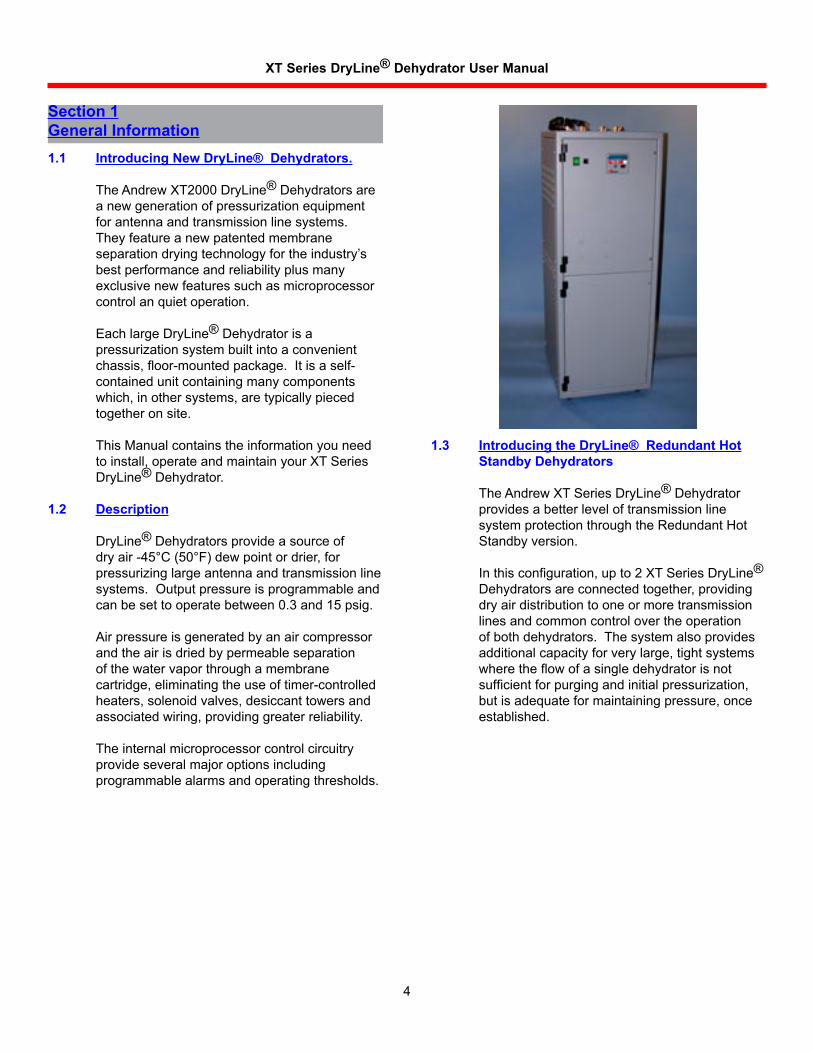
TheAndrewXT2000DryLine®Dehydratorsareanewgenerationofpressurizationequipmentforantennaandtransmissionlinesystems.Theyfeatureanewpatentedmembraneseparationdryingtechnologyfortheindustry’sbestperformanceandreliabilityplusmanyexclusivenewfeaturessuchasmicroprocessorcontrolanquietoperation.
EachlargeDryLine®Dehydratorisapressurizationsystembuiltintoaconvenientchassis, floor-mounted package. It is a self-containedunitcontainingmanycomponentswhich,inothersystems,aretypicallypiecedtogetheronsite.
This Manual contains the information you need toinstall,operateandmaintainyourXTSeriesDryLine®Dehydrator.
1.2 Description
DryLine®Dehydratorsprovideasourceofdryair-45°C(50°F)dewpointordrier,forpressurizinglargeantennaandtransmissionlinesystems.Outputpressureisprogrammableandcanbesettooperatebetween0.3and15psig.
Airpressureisgeneratedbyanaircompressorandtheairisdriedbypermeableseparationofthewatervaporthroughamembranecartridge,eliminatingtheuseoftimer-controlledheaters,solenoidvalves,desiccanttowersandassociatedwiring,providinggreaterreliability.
Theinternalmicroprocessorcontrolcircuitryprovideseveralmajoroptionsincludingprogrammablealarmsandoperatingthresholds.
1.3 Introducing the DryLine® Redundant Hot Standby Dehydrators
TheAndrewXTSeriesDryLine®DehydratorprovidesabetterleveloftransmissionlinesystemprotectionthroughtheRedundantHotStandbyversion.
In this configuration, up to 2 XT Series DryLine®Dehydratorsareconnectedtogether,providingdryairdistributiontooneormoretransmissionlinesandcommoncontrolovertheoperationofbothdehydrators.Thesystemalsoprovidesadditionalcapacityforverylarge,tightsystemswhere the flow of a single dehydrator is not sufficient for purging and initial pressurization, butisadequateformaintainingpressure,onceestablished.
XT Series DryLine® Dehydrator User Manual
5
Section 2Installation2.1 Unpack Dehydrator and Inspect for Shipping
Damage
Carefullyremovepackingmaterial.
Checkthedehydratorandlinemonitorforshippingdamagesuchasdentsorlooseparts.
Openthedehydratorfrontdoorandcheckforloosewires,hoses,orcomponents.
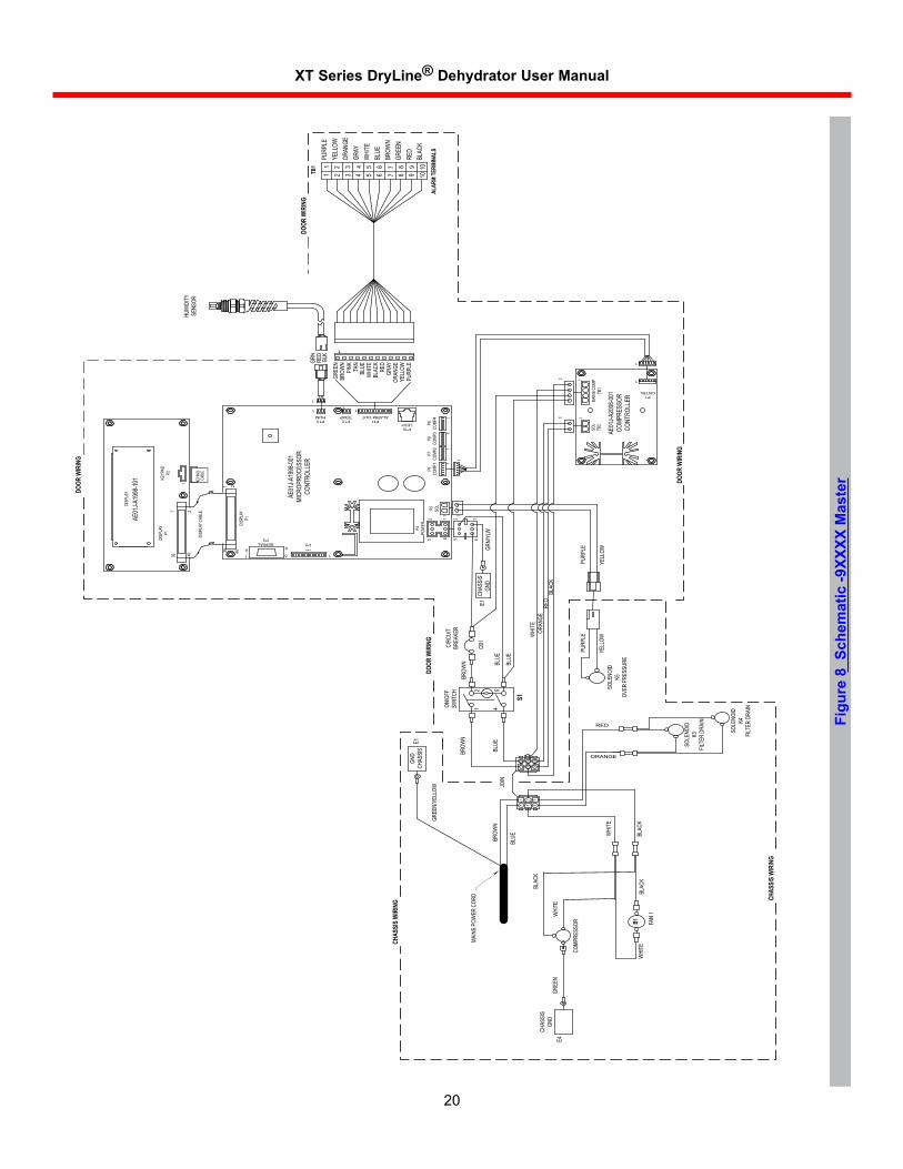
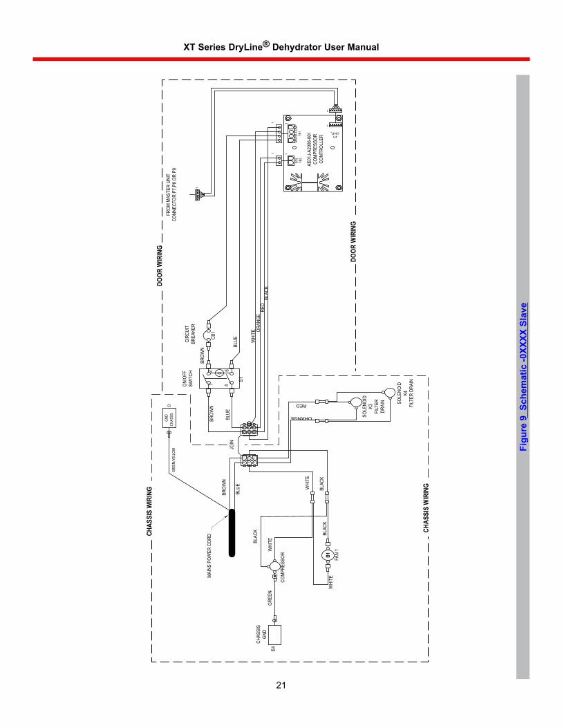
Ifanythingisloose,refertothepipingschematicFigure7orthewiringschematicFigure8andFigure9forproperplacement.
Ifthereisdamageorifthereareanyotherproblems,contactAndrewTechnicalService.TelephonenumbersarelistedinSection10.
Ifeverythinglookscorrect,closethedehydratorfrontdoor.
2.2 Perform Pre-System Startup Test
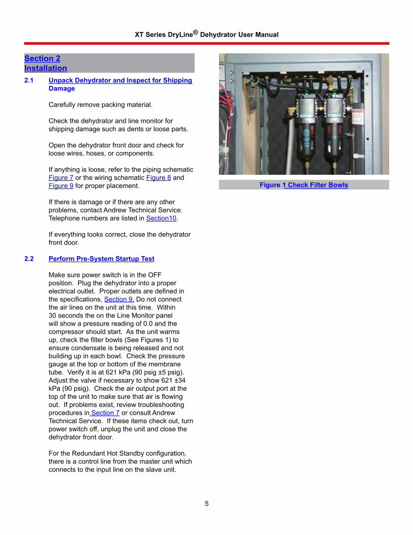
Make sure power switch is in the OFF position.Plugthedehydratorintoaproperelectrical outlet. Proper outlets are defined in the specifications, Section9.Donotconnecttheairlinesontheunitatthistime.Within30 seconds the on the Line Monitor panel willshowapressurereadingof0.0andthecompressorshouldstart.Astheunitwarmsup, check the filter bowls (See Figures 1) to ensurecondensateisbeingreleasedandnotbuildingupineachbowl.Checkthepressuregaugeatthetoporbottomofthemembranetube.Verifyitisat621kPa(90psig±5psig).Adjustthevalveifnecessarytoshow621±34kPa(90psig).Checktheairoutputportatthetop of the unit to make sure that air is flowing out.Ifproblemsexist,reviewtroubleshootingproceduresinSection7orconsultAndrewTechnicalService.Iftheseitemscheckout,turnpowerswitchoff,unplugtheunitandclosethedehydratorfrontdoor.
For the Redundant Hot Standby configuration, thereisacontrollinefromthemasterunitwhichconnectstotheinputlineontheslaveunit.
Figure 1 Check Filter Bowls
XT Series DryLine® Dehydrator User Manual
6
2.3 Place the Dehydrator
TheXTSeriesDryLine®Dehydratorisdesignedfor to be floor standing. The unit is shipped with thepowercordandairlinesplacedthroughthetopoftheunit.
2.4 Install Polyethylene Tubing Lines
Outputlines(4)withindividualvalves.
Pressuresenseline
FortheRedundantversion,theslaveunitsenseline.
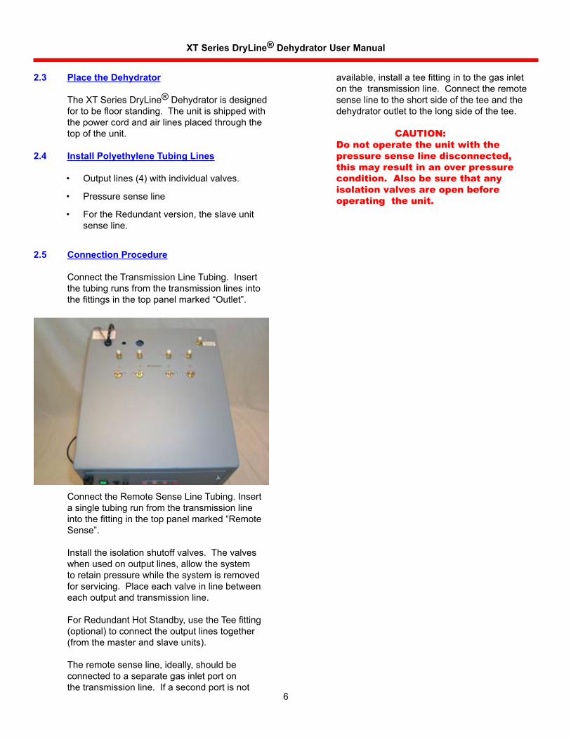
2.5 Connection Procedure
ConnecttheTransmissionLineTubing.Insertthetubingrunsfromthetransmissionlinesintothe fittings in the top panel marked “Outlet”.
•
•
•
ConnecttheRemoteSenseLineTubing.Insertasingletubingrunfromthetransmissionlineinto the fitting in the top panel marked “Remote Sense”.
Installtheisolationshutoffvalves.Thevalveswhenusedonoutputlines,allowthesystemtoretainpressurewhilethesystemisremovedforservicing.Placeeachvalveinlinebetweeneachoutputandtransmissionline.
For Redundant Hot Standby, use the Tee fitting (optional)toconnecttheoutputlinestogether(fromthemasterandslaveunits).
Theremotesenseline,ideally,shouldbeconnectedtoaseparategasinletportonthetransmissionline.Ifasecondportisnot
available, install a tee fitting in to the gas inlet onthetransmissionline.Connecttheremotesenselinetotheshortsideoftheteeandthedehydratoroutlettothelongsideofthetee.
CAUTION:Do not operate the unit with the pressure sense line disconnected, this may result in an over pressure condition. Also be sure that any isolation valves are open before operating the unit.
XT Series DryLine® Dehydrator User Manual
7
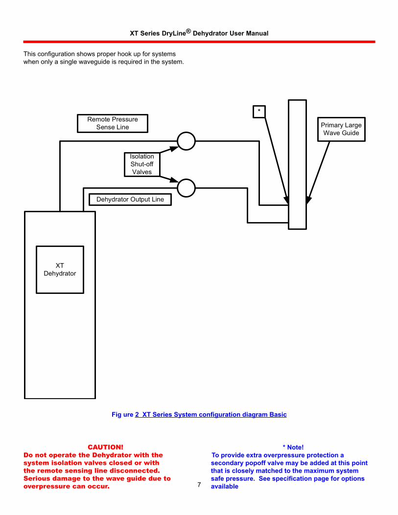
This configuration shows proper hook up for systems whenonlyasinglewaveguideisrequiredinthesystem.
CAUTION!Do not operate the Dehydrator with the system isolation valves closed or with the remote sensing line disconnected. Serious damage to the wave guide due to overpressure can occur.
* Note! To provide extra overpressure protection a secondary popoff valve may be added at this point that is closely matched to the maximum system safe pressure. See specification page for options available
XTDehydrator
RemotePressureSenseLine
IsolationShut-offValves
DehydratorOutputLine
PrimaryLargeWaveGuide
*
Fig ure 2 XT Series System configuration diagram Basic
XT Series DryLine® Dehydrator User Manual
8
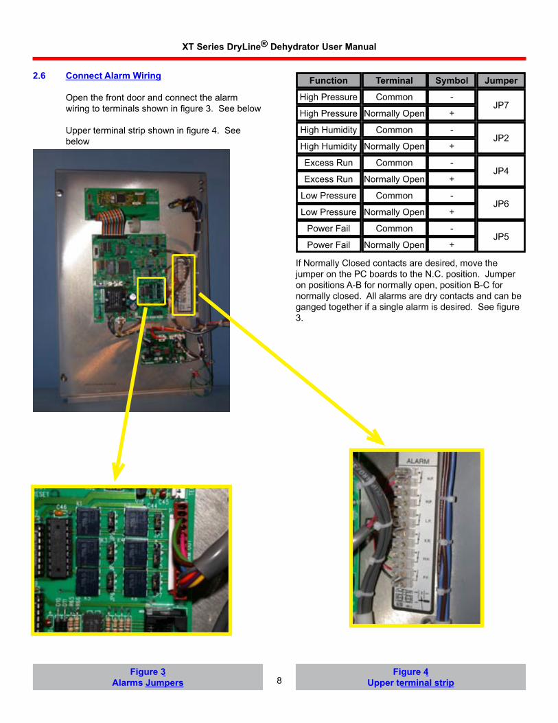
2.6 Connect Alarm Wiring
Openthefrontdoorandconnectthealarmwiring to terminals shown in figure 3. See below
Upper terminal strip shown in figure 4. See below
Figure 3Alarms Jumpers
Figure 4Upper terminal strip
IfNormallyClosedcontactsaredesired,movethejumperonthePCboardstotheN.C.position.JumperonpositionsA-Bfornormallyopen,positionB-Cfornormallyclosed.Allalarmsaredrycontactsandcanbeganged together if a single alarm is desired. See figure 3.
Function Terminal Symbol Jumper
HighPressure
HighPressure
HighHumidity
HighHumidity
ExcessRun
ExcessRun
LowPressure
LowPressure
PowerFail
PowerFail
Common
Common
Common
Common
Common
NormallyOpen
NormallyOpen
NormallyOpen
NormallyOpen
NormallyOpen
-
-
-
-
-
+
+
+
+
+JP7
JP2
JP4
JP6
JP5
XT Series DryLine® Dehydrator User Manual
9
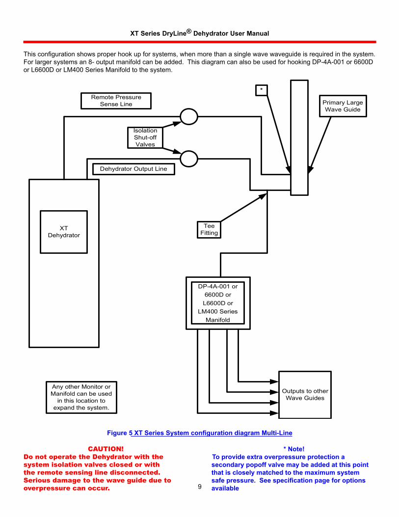
This configuration shows proper hook up for systems, when more than a single wave waveguide is required in the system. Forlargersystemsan8-outputmanifoldcanbeadded.ThisdiagramcanalsobeusedforhookingDP-4A-001or6600Dor L6600D or LM400 Series Manifold to the system.
CAUTION!Do not operate the Dehydrator with the system isolation valves closed or with the remote sensing line disconnected. Serious damage to the wave guide due to overpressure can occur.
* Note!To provide extra overpressure protection a secondary popoff valve may be added at this point that is closely matched to the maximum system safe pressure. See specification page for options available
XTDehydrator
RemotePressureSenseLine
IsolationShut-offValves
DehydratorOutputLine
PrimaryLargeWaveGuide
*
Anyother MonitororManifoldcanbeused
inthislocationtoexpandthesystem.
OutputstootherWaveGuides
TeeFitting
DP-4A-001or6600Dor
L6600DorLM400Series
Manifold
Figure 5 XT Series System configuration diagram Multi-Line
XT Series DryLine® Dehydrator User Manual
10
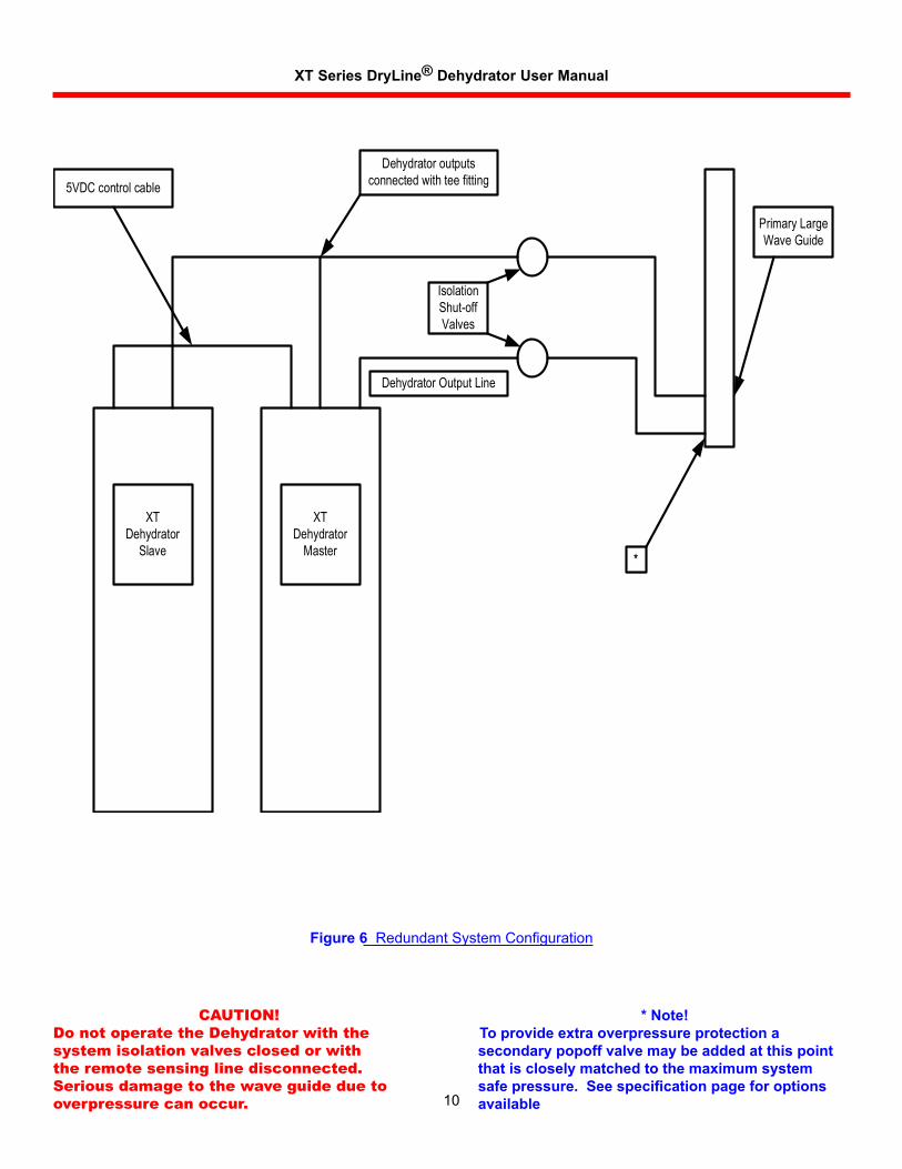
Figure 6 Redundant System Configuration
CAUTION!Do not operate the Dehydrator with the system isolation valves closed or with the remote sensing line disconnected. Serious damage to the wave guide due to overpressure can occur.
* Note!To provide extra overpressure protection a secondary popoff valve may be added at this point that is closely matched to the maximum system safe pressure. See specification page for options available
XTDehydrator
Master
Dehydratoroutputsconnectedwith teefitting
IsolationShut-offValves
DehydratorOutputLine
PrimaryLargeWaveGuide
*
XTDehydrator
Slave
5VDCcontrolcable
XT Series DryLine® Dehydrator User Manual
11
2.7 Connect to Dry Air Cable System Caution:
Checkthesystempressureratingbeforeconnectingthedehydratortothetransmissionlinesystem.Iftheratingisbelow35kPa(5.0psig),theoutputpressureofthedehydratorshouldbeadjusted.SeeSection4.Toinsurethatallinternaldehydratorcomponentsareproperlydried;operatetheXTSeriesDryLine®Dehydratorunitforatleast45minutespriortoconnectingtheoutputairlinetotheprimarywaveguide.
Ifthetransmissionlineshavenotbeenpurged,takethefollowingstepstodrythesystem;otherwise,proceedtoSection3,ControlsandDisplays.
2.7.1 Purging Procedure
Determinetotalvolumeofthepressurizeddryaircablesystemtobeconnectedtothedehydrator. Refer to “Table 2 - Times to Purge and Times to Pressurize.” Remember iftheRedundantHotStandbyoptionisused,thesetimescanbecutinhalf(approximately).
Opentheoppositeendofthecablesystemfromthedehydratorforpurging.
Operatethedehydrator(aftertheinitial45minutedryingperiod)todeliverdryairintothepressurizedairsystemuntilatotalof3volumeshavebeenpumpedthroughtheentiresystem.
Checkthehumidityinthesystemusingthehumidityalarm.Performthischeckafterthefarendofthesystemhasbeenclosedandthesystemhasbeenstabilizedforatleast5hours.
Checkcycletiming.Compressorontimeshouldbenomorethan10%ofofftimeformaximumlife.Ifnot:
Systemmaynotbeproperlysized.
Or
Leaksmayexist.CheckusingSnoopordetergentwater.
Or
Normalconnectorleakagemaybegreaterthanexpected.
1.
2.
3.
4.
5.
Duringtheoffcycle,thedehydratorisdesignedtoallowasmallamountofsystemairtobleedbackthroughthemembranedryer.Thisairmaintainsthedrynessofthemembranedryer.Assystemairbleedsbackthroughthedryer,additionalsystemmoistureiscontinuallyremoved,loweringthesystemdewpointevenfurther.
Yoursystemisnowupandrunningatthefactory
programmedsettings.Tobecomefamiliarwiththemicroprocessorcontrolsandtochangethesettings,proceedtoSection3,ControlsandDisplays.
Connectthealarmwiringtotheterminalsontheinsideoftheunit.Refertothelabelonthealarmboardortheschematicfortheproperconnections.
2.8 Connect to Power Supply
TheXTSeriescanbepluggedintoastandard20Apowerreceptacleoftheratedvoltage.
Electricalconnectionsrequiringseparatecircuitswhenmultipledehydratorsareinstalled.
Connectthedehydratortoaproperlygroundedpower outlet. Power is specified inSection9,Physical Specifications.
2.8.1 Grounding Instructions
Thisproductshouldbegrounded.Intheeventofanelectricalshortcircuit,groundingreducestheriskofelectricshockbyprovidinganescapepathfortheelectriccurrent.Thisproductisequippedwithacordhavingagroundingwireandagroundingplug.Itshouldbepluggedintoaproperlyinstalledoutletthatisgroundedinaccordancewithalllocalcodesandordinances.
Danger:Improper installation of the grounding plug can result in a risk of electric shock. If repair or replacement of the cord or plug is necessary, do not connect the green grounding wire to either flat blade terminal. Check with a qualified electrician or serviceman if you have any questions regarding grounding or if in doubt as to whether the product is properly grounded.
XT Series DryLine® Dehydrator User Manual
12
ConnectiontoaHaloGroundingSystem:A#10groundingstudislocatedattheinsidepowerentryareaofthedehydratorchassisfordirectconnectionstoahalogroundingsystem,whereapplicable.ConnectusingaNo.6copperstrandedwire,terminatedatthegroundstudwithaproperringtonguecrimp-onterminal.
2.8.2 Plug and Outlet Configurations
Make sure that the units are connected to an outlet having the same configuration as the plug. Do not modify the plug. If it will not fit theoutlet,haveaproperoutletinstalledbyaqualified electrician. Do not use an adapter. If theproductmustbereconnectedforuseonadifferent type of electric circuit, qualified service personnelshouldmakethere-connection.
2.9 Test the Unit
Turnonthedehydrator.Thedisplayshouldindicate0.0pressurewithinthirtyseconds.Thehumidityalarm,low-pressurealarm,pressurereadingand,eventually,theexcessruntimealarm (if so equipped) should flash in sequence inthedisplaywindow.Thealarmconditionsexistbecausetheunitisnotconnectedtothesystem.
XT Series DryLine® Dehydrator User Manual
13
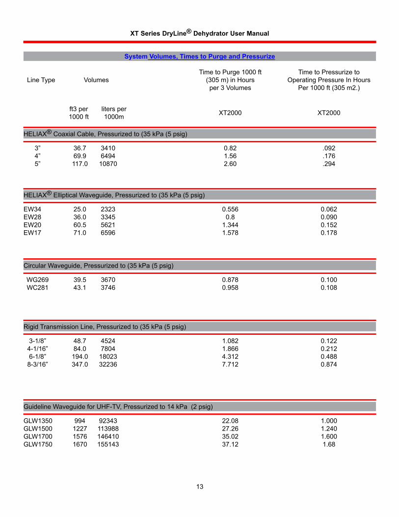
System Volumes, Times to Purge and Pressurize
LineType VolumesTimetoPurge1000ft
(305m)inHoursper3Volumes
TimetoPressurizetoOperatingPressureInHours
Per1000ft(305m2.)
ft3per1000ft
litersper1000m XT2000 XT2000
HELIAX®CoaxialCable,Pressurizedto(35kPa(5psig)
HELIAX®EllipticalWaveguide,Pressurizedto(35kPa(5psig)
CircularWaveguide,Pressurizedto(35kPa(5psig)
RigidTransmissionLine,Pressurizedto(35kPa(5psig)
GuidelineWaveguideforUHF-TV,Pressurizedto14kPa(2psig)
3” 36.7 3410 0.82 .092 4” 69.9 6494 1.56 .176 5” 117.0 10870 2.60 .294
EW34 25.0 2323 0.556 0.062EW28 36.0 3345 0.8 0.090EW20 60.5 5621 1.344 0.152EW17 71.0 6596 1.578 0.178
WG269 39.5 3670 0.878 0.100 WC281 43.1 3746 0.958 0.108
3-1/8” 48.7 4524 1.082 0.122 4-1/16” 84.0 7804 1.866 0.212 6-1/8” 194.0 18023 4.312 0.488 8-3/16” 347.0 32236 7.712 0.874
GLW1350 994 92343 22.08 1.000GLW1500 1227 113988 27.26 1.240GLW1700 1576 146410 35.02 1.600GLW1750 1670 155143 37.12 1.68
XT Series DryLine® Dehydrator User Manual
14
Section 3Controls and Displays Thissectionexplainsthefunctionsofthe
controlsanddisplaysusedforoperationandprogrammingofthecontroller.
3.1 Dehydrator Controls
ON-OFF Doublepolepowerswitchcontrolsbothsidesof
theline.Built-inlightindicatespowerisON.
Circuit Breaker WhitetabindicatesoverloadconditionRe-
settable.
Fuse OnthecontrollerPCB.
3.2 Microprocessor Control Keys
Advancesdisplay(scrollsahead)tothenextdisplayorprogrammodewithoutchangingthevaluesinthemicroprocessormemory.
Entersintothemicroprocessormemorythevaluesdisplayedinthewindowandadvancesdisplay(scrollsahead)tothenextprogramordisplaymode.
Numericallyincreasedisplayedsettingsindisplaywindow.Whendepressedlongerthan1/2secondscrollingwilloccuratafasterrate.
Numericallydecreasedisplayedsettingsindisplaywindow.Whendepressedlongerthan1/2secondscrollingwilloccuratafasterrate.
Usedtoallowtheuserquickaccesstothesystemeventlog.Afterdepressingthisbutton,themostrecenteventwillbedisplayed.Theupanddownarrowbuttonsmaybeusedtobrowsethelog.
VIEWLOG
SELECT
ENTER
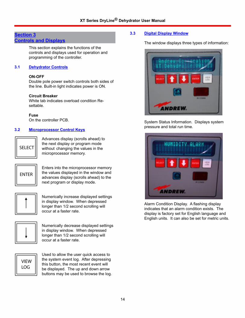
3.3 Digital Display Window
Thewindowdisplaysthreetypesofinformation:
SystemStatusInformation.Displayssystempressureandtotalruntime.
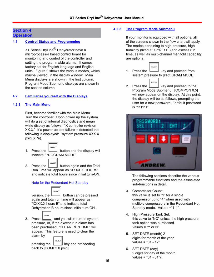
Alarm Condition Display. A flashing display indicatesthatanalarmconditionexists.ThedisplayisfactorysetforEnglishlanguageandEnglishunits.Itcanalsobesetformetricunits.
XT Series DryLine® Dehydrator User Manual
15
4.2.2 The Program Mode Submenu
Ifyourmonitorisequippedwithalloptions,allof the screens shown in the flow chart will apply. Themodespertainingtohigh-pressure,highhumidity (fixed at 7.5% R.H.) and excess run time,aswellasmulti-channelmanifoldcapabilityareoptions.
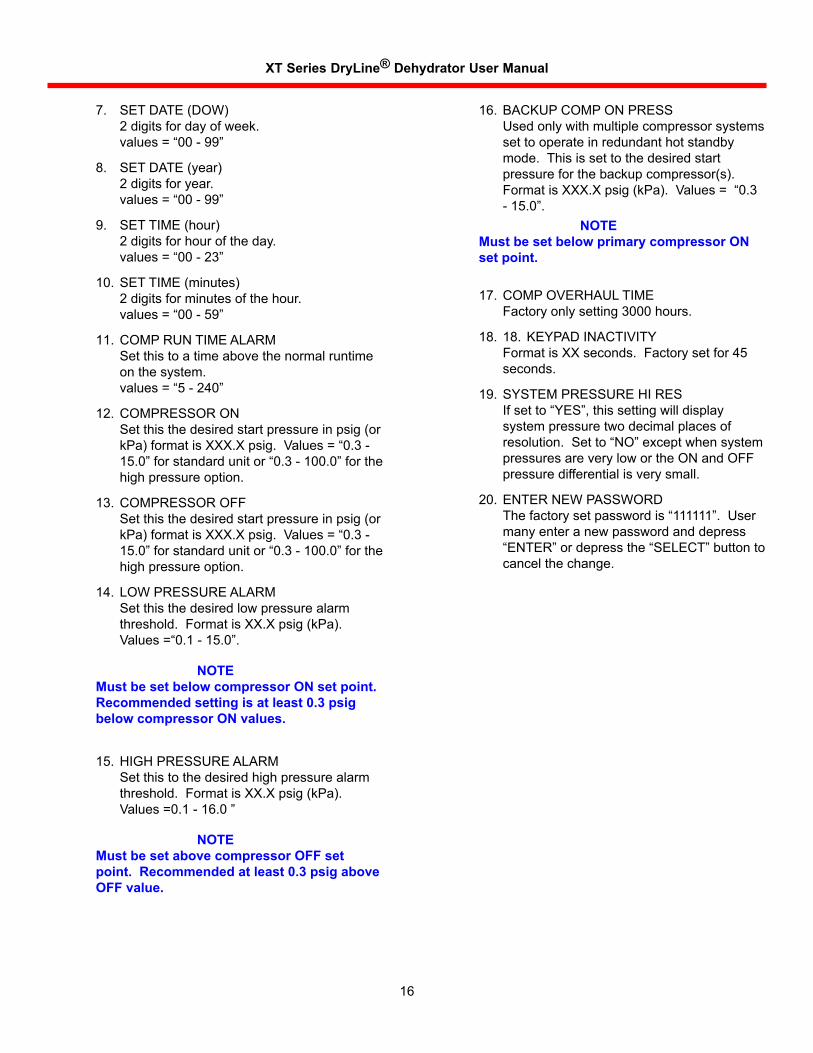
Pressthekeyandproceedfromsystem pressure to [PROGRAM MODE].
PressthekeyandproceedtotheProgram Mode Submenu. [COMPON 0.5] willnowappearonthedisplay.Atthispoint,thedisplaywillbeasfollows,promptingtheuser for a new password: “default password is “111111”.
1.
2.
4.1 Control Status and Programming
XTSeriesDryLine®Dehydratorhaveamicroprocessorbasedcontrolboardformonitoringandcontrolofthecontrollerandsettingtheprogrammablealarms.ItcomesfactorysetforEnglishlanguageandEnglishunits.Figure9showsthevariousmodes,whichmaybe viewed, in the display window. Main Menu displays are shown in the first column. Program Mode Submenu displays are shown in thesecondcolumn.
4.2 Familiarize yourself with the Displays
4.2.1 The Main Menu
First, become familiar with the Main Menu. Turnthecontroller.Uponpowerupthesystemwilldoasetofinternaldiagnosticsandmeanwhile display as follows: “X controller revision XX.X.” If a power-up test failure is detected the following is displayed: “system pressure XXX.X psig(kPa).
Pressthebuttonandthedisplaywillindicate “PROGRAM MODE”.
PressthebuttonagainandtheTotalRun Time will appear as “XXXX.X HOURS” andindicatetotalhourssinceinitialturn-ON.NotefortheRedundantHotStandbyversion,thebuttoncanbepressedagainandtotalruntimewillappearas;”XXXX.X hours B” and indicate total DehydrationBhourssinceinitialturnON.
Pressandyouwillreturntosystempressure,or,iftheexcessrunalarmhasbeen purchased, “CLEAR RUN TIME” will appear.Thisfeatureisusedtoclearthealarmbypressingthekeyandproceedingback to [COMP5.0 psig].
1.
2.
3.
Section 4Operation
SELECT
SELECT
SELECT
SELECT
ENTER
Thefollowingsectionsdescribethevariousprogrammablefunctionsandtheassociatedsub-functionsindetail.
CompressorCount:this valve is set to “1” for a single compressor up to “4” when used with multiplecompressorsintheRedundantHotStandby mode. Values =“1-4”.
HighPressureTankSet:this valve to “NO” unless the high pressure tankoptionwaspurchased.Values = “Y or N”.
SETDATE(month)2digitsformonthoftheyear.values = “01 - 12”
SETDATE(day)2digitsfordayofthemonth.values = “01 - 31”7.
3.
4.
5.
6.
SELECT
SELECT
XT Series DryLine® Dehydrator User Manual
16
SETDATE(DOW)2digitsfordayofweek.values = “00 - 99”
SETDATE(year)2digitsforyear.values = “00 - 99”
SET TIME (hour)2digitsforhouroftheday.values = “00 - 23”
SET TIME (minutes)2digitsforminutesofthehour.values = “00 - 59”
COMP RUN TIME ALARMSetthistoatimeabovethenormalruntimeonthesystem.values = “5 - 240”
COMPRESSOR ONSetthisthedesiredstartpressureinpsig(orkPa) format is XXX.X psig. Values = “0.3 -15.0” for standard unit or “0.3 - 100.0” for the highpressureoption.
COMPRESSOR OFFSetthisthedesiredstartpressureinpsig(orkPa) format is XXX.X psig. Values = “0.3 -15.0” for standard unit or “0.3 - 100.0” for the highpressureoption.
LOW PRESSURE ALARMSetthisthedesiredlowpressurealarmthreshold.FormatisXX.Xpsig(kPa).Values =“0.1 - 15.0”.
HIGH PRESSURE ALARMSetthistothedesiredhighpressurealarmthreshold.FormatisXX.Xpsig(kPa).Values =0.1 - 16.0 ”
7.
8.
9.
10.
11.
12.
13.
14.
15.
BACKUP COMP ON PRESSUsedonlywithmultiplecompressorsystemssettooperateinredundanthotstandbymode.Thisissettothedesiredstartpressureforthebackupcompressor(s).Format is XXX.X psig (kPa). Values = “0.3 - 15.0”.
COMP OVERHAUL TIMEFactoryonlysetting3000hours.
18. KEYPAD INACTIVITYFormatisXXseconds.Factorysetfor45seconds.
SYSTEM PRESSURE HI RESIf set to “YES”, this setting will display systempressuretwodecimalplacesofresolution. Set to “NO” except when system pressuresareverylowortheONandOFFpressuredifferentialisverysmall.
ENTERNEWPASSWORDThe factory set password is “111111”. User manyenteranewpasswordanddepress“ENTER” or depress the “SELECT” button to cancelthechange.
16.
17.
18.
19.
20.
NOTE Must be set below primary compressor ON
set point.
NOTE Must be set below compressor ON set point.
Recommended setting is at least 0.3 psig below compressor ON values.
NOTE Must be set above compressor OFF set
point. Recommended at least 0.3 psig above OFF value.
XT Series DryLine® Dehydrator User Manual
17
4.3 Pressure Monitoring and Control
4.3.1 Pressure Monitoring Points
Dehydratoroutputpressureismonitoredatthetransmission line on all models by the “Remote Sense” port on the top of the unit.
CAUTION: Do not operate the unit without the sense line connected, this may cause an over pressure condition that may damage the waveguide.
4.3.2 Dehydrator Duty Cycles
Thedehydratorisprogrammedatthefactorytostartwhentheoutputpressureofthedehydratordropsto3kPa(0.5psig)andstopwhenthepressurereaches35kPa(5.0psig).Thatistherecommendedpressurerangeformostantennaandtransmissionlinecomponents,whichhavearatingofatleast3kPa(0.5psig).
Somesystemcomponents,however,havelowerpressureratings.Usingtheproceduresdescribedbelow,XTSeriesDryLine®Dehydratorscanbeprogrammedforanystart/stoppressurecombinationinthe2-103kPa(0.3-15.0psig)range.
FortheRedundantHotStandbyversion,themasterunitisprogrammedtooperateat7kPa(1.0psig)andtheslaveunitisprogrammedtostartat3.5kPa(0.5psig).Bothunitsaresettostopat35kPa(5.0psig).
4.3.3 Display of System Pressure
The dehydrator output pressure “System Pressure 0.0” is the initial display as power is appliedtotheunit.
As shown in Figure 9, Main Menu, pressing the
Key will display “PROGRAM MODE” onthedisplaywindow.
4.3.4 Alarm Conditions
Alarmconditions,excepthighhumidity,aredefined by the programmed settings entered into themicroprocessorasdescribedbelow.Alarmcontactsareincludedintheunitandwiringterminalsarelocatedontheinsideofthedoor.
Whenanalarmconditionexists,thenormallyopencontactsareclosed,therebyactivatingaremotealarm(notincluded).Also,thealarmcondition will flash continually on the display windowuntilthealarmconditioniscorrected.Inthecaseoftheexcessrunalarm,thealarmmustbeclearedasdescribedintheprogrammingsection.
4.4 Programming Procedure
UsetheSELECTkeytoadvancethroughtheseriesofpromptswithoutchangingtheprogrammedvalues.Ifyouchangeavalueandwanttosaveittomemory,usetheENTERkey,whichwillalsoadvanceyoutothenextfeature.
With the “PROGRAM MODE” prompt displayed inthedisplaywindow,pressthe
key to proceed to the first programmablefeature.
4.5 Shutdown Procedure
Whenremovingyourdehydratorfromservice,youmayneedasubstitutedryairsource.CallAndrewTechnicalService.TelephonenumbersarelistedinSection10.
Beforeturningofftheunit,notifypersonnelthatalarmsmaybeactivated.
ToshutdowntheXTseriesunit,turntheON-OFFpowerswitchtotheOFFpositionandclosetheisolationshutoffvalveslocatedintheoutput/inputlinestoretainsystempressure.
Disconnectbyunscrewingthepolytubecompression fittings located at the top of the unit.
SELECT
SELECT
XT Series DryLine® Dehydrator User Manual
18
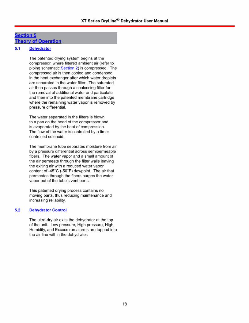
Section 5Theory of Operation5.1 Dehydrator
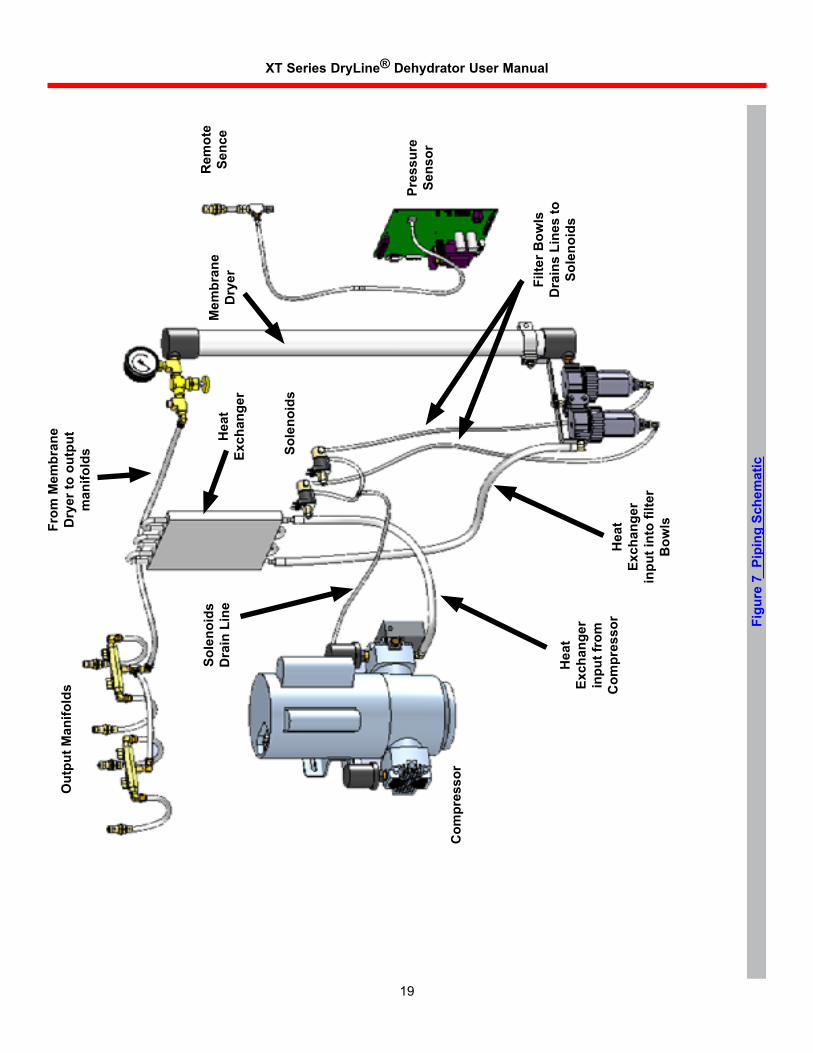
Thepatenteddryingsystembeginsatthecompressor, where filtered ambient air (refer to pipingschematicSection2)iscompressed.Thecompressedairisthencooledandcondensedintheheatexchangerafterwhichwaterdropletsare separated in the water filter. The saturated air then passes through a coalescing filter for theremovalofadditionalwaterandparticulateandthenintothepatentedmembranecartridgewheretheremainingwatervaporisremovedbypressuredifferential.
The water separated in the filters is blown toapanontheheadofthecompressorandisevaporatedbytheheatofcompression.The flow of the water is controlled by a timer controlledsolenoid.
Themembranetubeseparatesmoisturefromairbyapressuredifferentialacrosssemipermeablefibers. The water vapor and a small amount of the air permeate through the filter walls leaving theexitingairwithareducedwatervaporcontentof-45°C(-50°F)dewpoint.Theairthatpermeates through the fibers purges the water vaporoutofthetube’sventports.
Thispatenteddryingprocesscontainsnomovingparts,thusreducingmaintenanceandincreasingreliability.
5.2 Dehydrator Control
Theultra-dryairexitsthedehydratoratthetopoftheunit.Lowpressure,Highpressure,HighHumidity,andExcessrunalarmsaretappedintotheairlinewithinthedehydrator.
XT Series DryLine® Dehydrator User Manual
19
Rem
ote
Senc
e
Pres
sure
Se
nsor
Filte
r Bow
lsD
rain
s Li
nes
to
Sole
noid
sH
eat
Exch
ange
r in
put f
rom
C
ompr
esso
rH
eat
Exch
ange
r in
put i
nto
filte
r B
owlsFr
om M
embr
ane
Dry
er to
out
put
man
ifold
s
Sole
noid
s D
rain
Lin
eM
embr
ane
Dry
er
Out
put M
anifo
lds
Com
pres
sor
Hea
t Ex
chan
ger
Sole
noid
s
Figu
re 7
Pip
ing
Sche
mat
ic
XT Series DryLine® Dehydrator User Manual
20
Figu
re 8
Sch
emat
ic -9
XXXX
Mas
ter
XT S
CHEM
ATIC
- M
ASTE
R UN
IT (X
T UN
IT -9
XXXX
)
TB1
ALAR
M TE
RMIN
ALS
P1CNTRL
1
1
P5 SOL
2 1656
1
11
AE01
J-A20
06-0
01CO
MPRE
SSOR
CONT
ROLL
ERMAIN
S CO
MPTB
1SO
LTB
2
11
11
25
P4PO
WER
391
AE01
J-A19
98-0
01MI
CROP
ROCE
SSOR
CONT
ROLL
ER
***P3
1
9
5
DISP
LAY
P1
SERIALP2
6
1402
KEYP
ADP2
4039
21
1
AE01
J-A19
98-1
01
DISP
LAY
P1
14
2 3
5 6
14
25
36
HUMI
DITY
SENS
ORDI
SPLA
Y CA
BLE
KEYP
ADCA
BLE
DISP
LAY
CHAS
SIS
WIR
ING CH
ASSI
S W
IRIN
G
DOOR
WIR
ING
DOOR
WIR
ING
DOOR
WIR
ING
DOOR
WIR
ING
PURP
LE1 2 3 4 5 6 7 8 9 10
8 9763 4 521 10
YELL
OWOR
ANGE
GRAY
WHI
TEBL
UEBR
OWN
GREE
NRE
DBL
ACK
GREE
N
BLAC
KRE
D
BROW
N
BLUE
ORAN
GE
WHI
TE
GRAY
YELL
OWPU
RPLE
PINK TA
N
1
1
11
1
1P13HUM
P12TEMP
P11ALARM OUT
P10LED1
P6CO
MP1
P7CO
MP2
P8CO
MP3
P9CO
MP4
11
1
1
GRN
RED
BLK
GRN/
YLW
CHAS
SIS
GND
E1
E1
S1
CIRC
UIT
BREA
KER
BROW
N BLUE
WHI
TEOR
ANGE
RED
ON/O
FFSW
ITCH
BLUE
BLAC
K
CB1
12 5
4
PURP
LEPU
RPLE
YELL
OWSO
LENO
IDK5
OVER
PRE
SSUR
E
YELL
OW
SOLE
NOID
K4FI
LTER
DRA
IN
SOLE
NOID
K3FI
LTER
DRA
IN
WHI
TE
BLAC
K
RED
ORANGE
GND
CHAS
SIS
GREE
N/YE
LLOW
BROW
N
BLUE
BLAC
K
WHI
TE
JOIN
BROW
N
BLUE
MAIN
S PO
WER
COR
D
GREE
N
CHAS
SIS
GND
E4
COMP
RESS
OR
WHI
TEB1
BLAC
KFA
N 1
XT Series DryLine® Dehydrator User Manual
21
Figu
re 9
Sch
emat
ic -0
XXXX
Sla
ve
XT S
CHEM
ATIC
- SL
AVE
UN
IT (X
T U
NIT
-0XX
XX)
GRE
EN/Y
ELLO
WE1
GN
DCH
ASSI
S
P1CNTL
1
1
1
AE01
J-A2
006-
001
COM
PRES
SOR
CONT
ROLL
ERMAI
NS C
OMP
TB1
SOL
TB2
11
11
14
2 3
5 6
14
25
36
FROM
MAS
TER
UNIT
CONN
ECTO
R P7
,P8
OR P
9
DOOR
WIR
ING
DOOR
WIR
ING
CHAS
SIS
WIR
ING
CHAS
SIS
WIR
ING
CIRC
UIT
BREA
KER
ON/O
FFSW
ITCH
CB1
BROW
N
BROW
N
BLUE
JOIN
S1BL
UE WHI
TE ORAN
GERE
DBL
ACK
1 452
SOLE
NOID
K3FI
LTER
DR
AIN SO
LENO
IDK4
FILT
ER D
RAIN
RED
ORANGE
BLAC
K
WHI
TE
BLAC
K
FAN
1W
HITE
B1
COM
PRES
SOR
BLAC
K
WHI
TEGR
EEN
BLUE
BROW
N
MAI
NS P
OWER
COR
D
CHAS
SIS
GND
E4
XT Series DryLine® Dehydrator User Manual
22
Section 6Maintenance Thedehydratorrequiresmaintenance
semiannuallyandaftereach3000hoursofoperationtoensurecontinuedreliableoperation.
Danger:Service personnel should observe all safety regulations. Do not perform maintenance on equipment without first turning off the main power supply. Under certain conditions, dangerous potentials may exist when the main power supply controls are in the off position. Only qualified technicians should attempt to effect maintenance or repairs on electrical equipment.
Semi-Annual Maintenance.Thesemi-annualmaintenanceconsistsofapreventivemaintenanceinspectionandreplacementofthe compressor air filter. These tasks can be performed easily in the field as described below.
3000 hour Overhaul.Adehydratoroverhaulisrequiredafterthecompressorhasrunatotalof3000hours,asindicatedonthecompressorruntimemeter.Thedehydratoroverhaulincludesa compressor overhaul, water filter, high temperaturetubingandhoseclamps.
Thedehydratoroverhaulkit,seeSection8,includesallthenecessarypartsandinstructions.Or,ifyouprefer,Andrewoffersadehydratoroverhaulservice.ContactAndrewTechnicalService.TelephonenumbersarelistedinSection10.
RefertoSections8.4.7and8.4.10forprocedures to replace water filter elements.
In Case of Difficulty. Ifthedehydratorwillnotoperateorifthereareotherproblems,refertothetroubleshootingproceduresinSection7.
6.1 Semi-Annual Preventive Maintenance Inspection
Inspectionincludescheckingforlooseor damaged hoses, fittings and electrical connections.Checkthefollowingitems:
6.1.1 Check Water Filter and Coalescent Filter and Elements
Verifythereisnowaterbuild-upinthefilter bowls. If there is water, refer to the troubleshootingproceduresinSection7forcorrectiveaction.Replacementofthewaterfilter and coalescent filter and their associated elementsandbowlsiscoveredinthepartsreplacementsectionofthismanual.RefertoSection8.
6.1.2 Check Electrical Connections
Checkforlooseorcorrodedelectricalconnections.Alooseterminalcancauseerraticoperationandunnecessarydowntime.Checkthescrew-onandpush-onterminalsandtightenasrequired.
6.1.3 Check Ground Wire
Checkforpropergroundwireconnectiontoprotectoperationspersonnel.Agreengroundwireisattachedbetweenthepowerterminalstripandthedehydratorchassis.Thegroundlugscreworstudnutmustbetighttoprovideaproperground.
6.1.4 Check Run Time Meter
Checktheruntimemetertodeterminethedutycycleofthedehydrator.Ifthedehydratorhasbeenrunningmorethan10%ofthetime,checkforsystemleaks.Alsochecktoseeifitistimetoschedulethe3000-hourmaintenance.
6.1.5 Replace Compressor Air Filter
The air filter protects the compressor from contaminationandextendstheservicelifeofthecompressor.Itismadeofopencellmaterialandshouldbereplacedeverysixmonthsormoreoftenifthedehydratorislocatedinadustyenvironment.
Carefully pull off the filter cover and remove the filter element. Install the new filter element and replace the filter cover, being certain that it is completely seated. To replace the filter housing, unscrewthehousingfromthecompressorheadand replace with new filter housing.
XT Series DryLine® Dehydrator User Manual
23
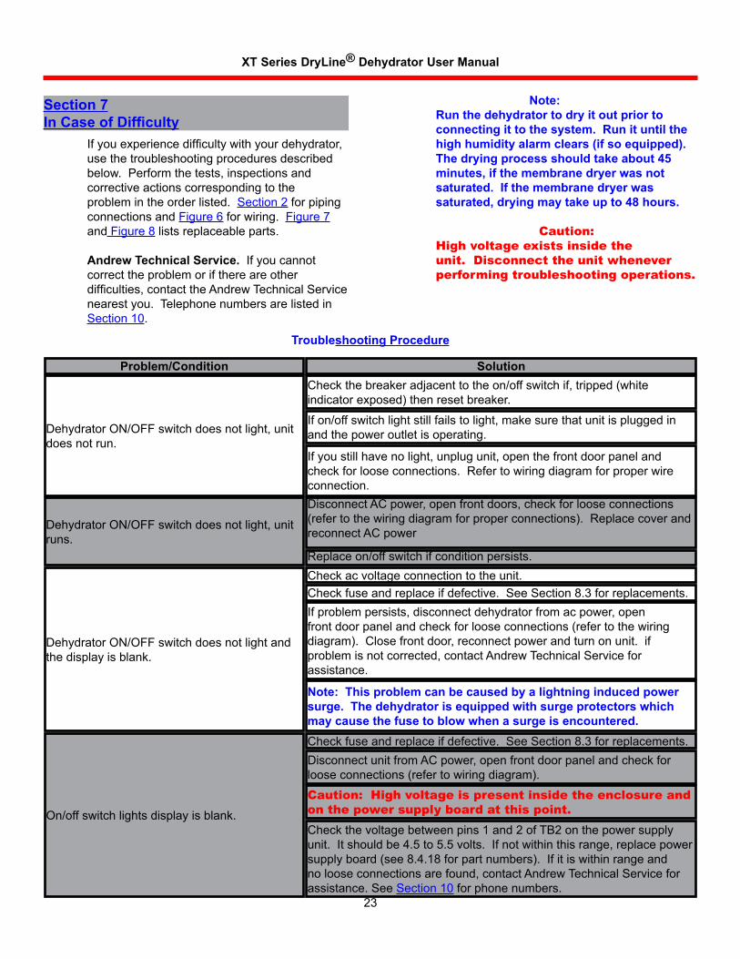
If you experience difficulty with your dehydrator, usethetroubleshootingproceduresdescribedbelow.Performthetests,inspectionsandcorrectiveactionscorrespondingtotheproblemintheorderlisted.Section2forpipingconnectionsandFigure6forwiring.Figure7andFigure8listsreplaceableparts.
Andrew Technical Service.Ifyoucannotcorrecttheproblemorifthereareotherdifficulties, contact the Andrew Technical Service nearestyou.TelephonenumbersarelistedinSection10.
Section 7In Case of Difficulty
Note: Run the dehydrator to dry it out prior to
connecting it to the system. Run it until the high humidity alarm clears (if so equipped). The drying process should take about 45 minutes, if the membrane dryer was not saturated. If the membrane dryer was saturated, drying may take up to 48 hours.
Caution:High voltage exists inside the unit. Disconnect the unit whenever performing troubleshooting operations.
Troubleshooting Procedure
Problem/Condition Solution
DehydratorON/OFFswitchdoesnotlight,unitdoesnotrun.
DehydratorON/OFFswitchdoesnotlight,unitruns.
DehydratorON/OFFswitchdoesnotlightandthedisplayisblank.
On/offswitchlightsdisplayisblank.
Checkthebreakeradjacenttotheon/offswitchif,tripped(whiteindicatorexposed)thenresetbreaker.
Ifon/offswitchlightstillfailstolight,makesurethatunitispluggedinandthepoweroutletisoperating.
Ifyoustillhavenolight,unplugunit,openthefrontdoorpanelandcheckforlooseconnections.Refertowiringdiagramforproperwireconnection.DisconnectACpower,openfrontdoors,checkforlooseconnections(refertothewiringdiagramforproperconnections).ReplacecoverandreconnectACpower
Replaceon/offswitchifconditionpersists.Checkacvoltageconnectiontotheunit.Checkfuseandreplaceifdefective.SeeSection8.3forreplacements.Ifproblempersists,disconnectdehydratorfromacpower,openfrontdoorpanelandcheckforlooseconnections(refertothewiringdiagram).Closefrontdoor,reconnectpowerandturnonunit.ifproblemisnotcorrected,contactAndrewTechnicalServiceforassistance.
Note: This problem can be caused by a lightning induced power surge. The dehydrator is equipped with surge protectors which may cause the fuse to blow when a surge is encountered.Checkfuseandreplaceifdefective.SeeSection8.3forreplacements.DisconnectunitfromACpower,openfrontdoorpanelandcheckforlooseconnections(refertowiringdiagram).
Caution: High voltage is present inside the enclosure and on the power supply board at this point.Checkthevoltagebetweenpins1and2ofTB2onthepowersupplyunit.Itshouldbe4.5to5.5volts.Ifnotwithinthisrange,replacepowersupplyboard(see8.4.18forpartnumbers).Ifitiswithinrangeandnolooseconnectionsarefound,contactAndrewTechnicalServiceforassistance.SeeSection10forphonenumbers.
XT Series DryLine® Dehydrator User Manual
24
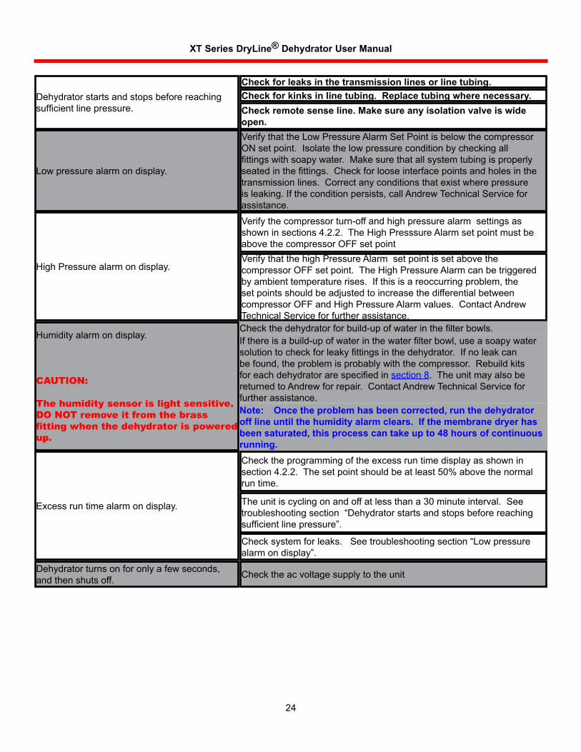
Dehydratorstartsandstopsbeforereachingsufficient line pressure.
Lowpressurealarmondisplay.
HighPressurealarmondisplay.
Humidityalarmondisplay.
CAUTION:
The humidity sensor is light sensitive. DO NOT remove it from the brass fitting when the dehydrator is powered up.
Excessruntimealarmondisplay.
Dehydratorturnsonforonlyafewseconds,andthenshutsoff.
Check for leaks in the transmission lines or line tubing.Check for kinks in line tubing. Replace tubing where necessary.Check remote sense line. Make sure any isolation valve is wide open.VerifythattheLowPressureAlarmSetPointisbelowthecompressorONsetpoint.Isolatethelowpressureconditionbycheckingallfittings with soapy water. Make sure that all system tubing is properly seated in the fittings. Check for loose interface points and holes in the transmissionlines.Correctanyconditionsthatexistwherepressureisleaking.Iftheconditionpersists,callAndrewTechnicalServiceforassistance.
Verifythecompressorturn-offandhighpressurealarmsettingsasshowninsections4.2.2.TheHighPresssureAlarmsetpointmustbeabovethecompressorOFFsetpointVerifythatthehighPressureAlarmsetpointissetabovethecompressorOFFsetpoint.TheHighPressureAlarmcanbetriggeredbyambienttemperaturerises.Ifthisisareoccurringproblem,thesetpointsshouldbeadjustedtoincreasethedifferentialbetweencompressorOFFandHighPressureAlarmvalues.ContactAndrewTechnicalServiceforfurtherassistance.Check the dehydrator for build-up of water in the filter bowls.If there is a build-up of water in the water filter bowl, use a soapy water solution to check for leaky fittings in the dehydrator. If no leak can befound,theproblemisprobablywiththecompressor.Rebuildkitsfor each dehydrator are specified in section8.TheunitmayalsobereturnedtoAndrewforrepair.ContactAndrewTechnicalServiceforfurtherassistance.Note: Once the problem has been corrected, run the dehydrator off line until the humidity alarm clears. If the membrane dryer has been saturated, this process can take up to 48 hours of continuous running.Checktheprogrammingoftheexcessruntimedisplayasshowninsection4.2.2.Thesetpointshouldbeatleast50%abovethenormalruntime.
Theunitiscyclingonandoffatlessthana30minuteinterval.Seetroubleshooting section “Dehydrator starts and stops before reaching sufficient line pressure”.
Check system for leaks. See troubleshooting section “Low pressure alarm on display”.
Checktheacvoltagesupplytotheunit
XT Series DryLine® Dehydrator User Manual
25
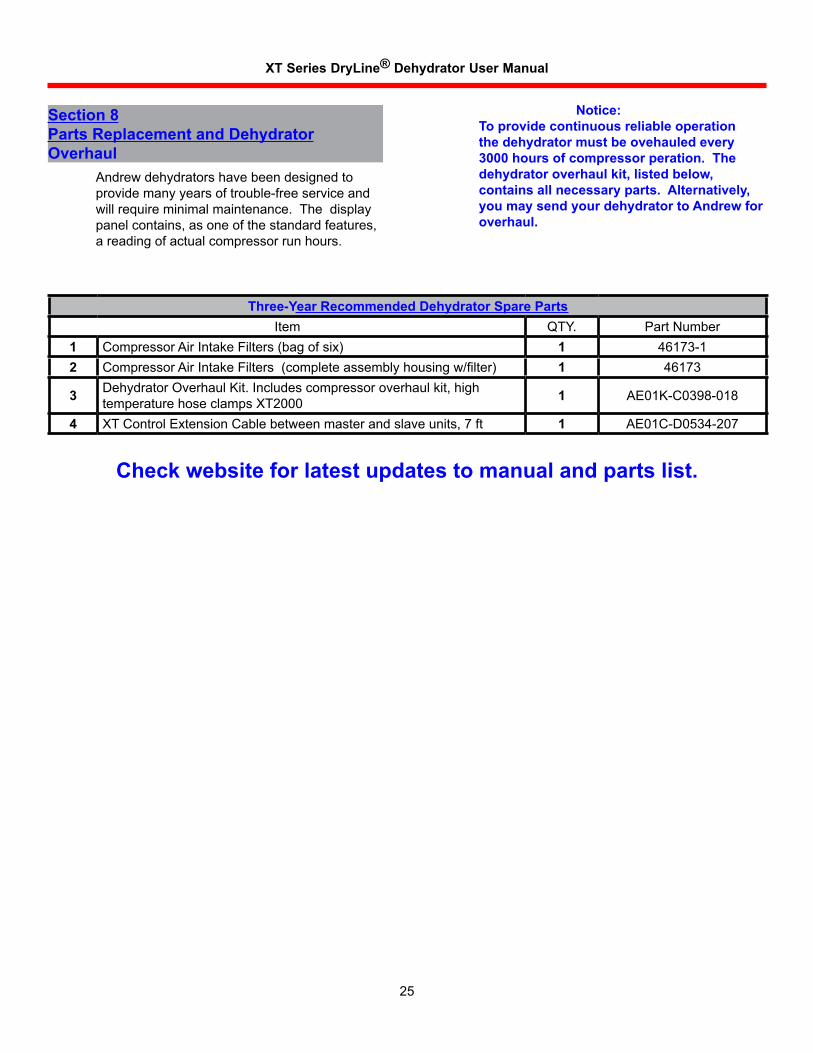
Section 8Parts Replacement and Dehydrator Overhaul Andrewdehydratorshavebeendesignedto
providemanyyearsoftrouble-freeserviceandwillrequireminimalmaintenance.Thedisplaypanelcontains,asoneofthestandardfeatures,areadingofactualcompressorrunhours.
Notice: To provide continuous reliable operation
the dehydrator must be ovehauled every 3000 hours of compressor peration. The dehydrator overhaul kit, listed below, contains all necessary parts. Alternatively, you may send your dehydrator to Andrew for overhaul.
Check website for latest updates to manual and parts list.
Three-Year Recommended Dehydrator Spare PartsItem QTY. PartNumber
1 CompressorAirIntakeFilters(bagofsix) 1 46173-12 Compressor Air Intake Filters (complete assembly housing w/filter) 1 46173
3 Dehydrator Overhaul Kit. Includes compressor overhaul kit, high temperaturehoseclampsXT2000 1 AE01K-C0398-018
4 XTControlExtensionCablebetweenmasterandslaveunits,7ft 1 AE01C-D0534-207
XT Series DryLine® Dehydrator User Manual
26
8.1 Parts Replacement Procedures
Whenthedehydratorruntimereaches3000hours,itwillbenecessarytorebuildthecompressorandreplacethehoses,clamps,water and coalescent filter elements. The necessarypartsandinstructionsareincludedintheoverhaulkit,listedinSection8.
FollowingareproceduresforreplacementofthepartslistedinSection8.
8.2 Unit Shutdown and Removal
InordertoperformpartsreplacementontheXTSeriesDryLine®Dehydrators,itwillbenecessarytoturnofftheunitandremovethemfromservice.Asthisisdone,oneormoreofthealarmsmaybeactivated.Personnelwhomaybemonitoringthesealarmsshouldbeinformedpriortotheunitsbeingturnedoff.Itwillalsobenecessarytocloseoffthetransmissionlinesconnectedtothedehydratortoavoidlosingpressureintheselines.Oncethesestepshavebeentaken,turnoffthepowertobothunits,disconnectthealarmconnectionsandunplugtheunit.Theunitscannowbemovedtoasuitablework tableforpartsreplacement.
8.3 Door and Panel Removal
Caution: Disconnect electrical power from the unit before removing the doors.
Carefullyloosenthescrewsinthefrontdoorsandswingthemopen.
Loosenthescrewsinthesidepanelsandremovethesidepanelsbyliftingthemawayfromtheunit.
8.4 Replace Power Switch
Disconnectthefourquickdisconnectconnectorsfromthepowerswitch,carefullynotingthelocationofeachwire.Compresstheretainersontheswitchandpushtheswitchoutthefrontofthechassis.Itmaybenecessarytorocktheswitchfromtoptobottomtoremoveit.Replaceswitch,bysnappingitinplace.Reconnectthefourwires.
8.5 Replace Circuit Breaker
Thecircuitbreakerislocatedontheupperfrontdoorofthedehydrator.Disconnectthetwoquickdisconnectconnectorsfromthecircuitbreaker,carefullynotingthelocationofeachwire.
Toremovethecircuitbreaker,compresstheretainersonbothsidesandpushitthroughthefrontpanelopening.Replacecircuitbreaker,snappingitinplace.Reconnectthetwowires.
8.6 Replace Compressor Control PCB
ThecompressorcontrolPCBcontrolsthecompressorON/OFFcycles,solenoiddrainvalvetimingandmonitorsthecompressorcurrentsensing.ToremovethecontrolPCB,openthefrontdooroftheunit.DisconnectthecableconnectorsfromthethreelocationsonthePCB.RemovethehardwarewhichscrewthecontrolPCBtothedoor.InstallthereplacementcontrolPCBbyreversingtheaboveprocess.
8.7 Replace Compressor
8.7.1 Disconnect Wiring
Withthesidedoorsremoved,removethecoverplateonthecompressorcoveringtheelectricalconnections.Removethegroundscrewandremovethegreenwirefromtheconnectionbox.Usingwirecutters,cutthewhiteandblackleadsasclosetothebuttspliceaspossible.Trim3/8inch(10mm)ofinsulationfromthewire(s)andinstallthereplacementbuttspliceonthesetwowires,leavingthecompressorendofthespliceun-crimped.Thiswillbeusedlatertoconnecttothereplacementcompressor.Thecompressorshouldnowbefreeofanyelectricalconnectiontotheunit.
8.7.2 Disconnect Tubing Removethemilkywhitehosewhichrunsfrom
thecompressoroutlettotheheatexchangerinlet.Againitmaybenecessarytocuttheclampandhosetoremoveitfromtheheatexchanger.Usingtheoldtubingasatemplate,cutthereplacementtubingtolengthusingasharpknife.Removethedrippanassemblyfromtheheadoftheoldcompressorandremountittothereplacementcompressor.Thecompressorassemblyshouldnowbefreeofalltubingconnections.
XT Series DryLine® Dehydrator User Manual
27
8.7.3 Compressor Remount and Reassembly Remove the bolts [ (4) XT2000 ] which secure
thecompressortothebackmountingplate.Carefullyremovethecompressorassemblyfromthechassis.
Mount the compressor assembly to the back mountingplateusingtheexistinghardware.Donotovertightenthemountingscrews.
Reconnectthehosesclamps,(assuppliedwiththecompressorreplacementkit)andwiring.
8.8 Replace Heat Exchanger
Theheatexchangerislocatedatrightsideoftheunitunderthesidepanel.Undernormalconditionstheheatexchangershouldnotneedtobereplaced.
Replaceitifthedehydratorhasbeendroppedorotherwisedamagedsuchthattheheatexchangerisleakingair.
8.9 Replace Water Filter Element - 3000 hour Maintenance
Replace the water filter after each 3000 hours of operation.
Whenambientroomairiscompressedinthedehydratorcompressor,liquidwaterisformed.Thisliquidwatermustberemovedinordertoallowthemembranedryertofunctionatitspeakefficiency. As the air exits the compressor, it is cooledintheheatexchangerandthenentersinto the water filter. The air swirls around the inside of the filter bowl, separating the liquid water out on the sides of the filter bowl. A 5.0 micron filter is also provided in the water filter to prevent water droplets from exiting the filter. This 5.0 micron filter also filters out any dust particlesorothercontaminantswhichwouldlessen the efficiency of the membrane dryer.
To replace the filter element, twist and remove the filter bowl from the cast housing. Unscrew the filter element from the cast filter housing and replace with a new filter. Do not attempt to clean the filter element. If it is necessary to clean the filter bowl, use a mild soap and water solution andrinsewithwater.Donotusesolvents.Reassembletheunitbyreversingtheaboveprocedure.Checkforleaksbyturningtheunitonandapplyingadilutedetergentandwater
solutionatthebowl/housingsealandatthehosefittings which were reconnected. If no leaks are found,theunitisreadytoreturntoservice.Ifleaksarelocated,repairtheleakandrecheckfor additional leaks. Leaking fittings must be repairedortheunitwillnotfunctionproperlyandcanresultindamagetothetransmissionlinesystem.
8.10 Replace Coalescing Filter Element
The coalescing filter is located downstream from the water filter. Its function is to remove any “water fog” which may still be present in the air leaving the water filter. The coalescing filter traps any fine liquid water particles, including aerosolsandcausesthemtocoalesceintolargerdroplets.Thesedropletsfalltothebottomofthebowlandareblownoutandcarriedtothecompressorhead,wheretheyevaporate.
To replace the filter element, twist and remove the filter bowl from the cast housing. Unscrew the filter element from the cast filter housing and replace with a new filter. Do not attempt to clean the filter element. If it is necessary to clean the filter bowl, use a mild soap and water solution andrinsewithwater.Donotusesolvents.Reassembletheunitbyreversingtheaboveprocedure.Checkforleaksbyturningtheunitonandapplyingadilutedetergentandwatersolutionatthebowl/housingsealandatthehosefittings which were reconnected. If no leaks are found,theunitisreadytoreturntoservice.Ifleaksarelocated,repairtheleakandrecheckfor additional leaks. Leaking fittings must be repairedortheunitwillnotfunctionproperlyandcanresultindamagetothetransmissionlinesystem.
8.11 Replace Cooling Fan Thecoolingfanventilatesthedehydrator
enclosurethuscoolingthecompressorandtheheatexchanger.Failureofafancanresultinsaturationofthemembranedryeranddamagetothecompressor.
Toremoveafan,disconnectthefanleadsandremovethemountinghardware.Installthereplacementfanusingtheexistinghardware.Orientationoftheacpowerleadsisnotcritical.
XT Series DryLine® Dehydrator User Manual
28
8.12 Replace Microprocessor Board
Themicroprocessorboardassemblyincludesthedisplay,themicroprocessor,compressorpressuresensor,theprocessorcontainingthemicroprocessorprogramming,aswellasotherelectroniccomponents.Acomponentfailureonthemicroprocessorcircuitcardwillnecessitatereplacementoftheentirecircuitboardassembly.
Toremovethemicroprocessorcircuitboardassembly,openthefrontdoorontheunit.Disconnectthewiringfromthemicroprocessorcircuitboardbeingcarefultonotethelocationofeachwireasitisremoved.Removethehardwarewhichsecurestheboardtothedoorpanel,andremovethemicroprocessorcircuitboard.Installthereplacementmicroprocessorcircuitcardassemblybyreversingtheaboveprocess.
XT Series DryLine® Dehydrator User Manual
29
Section 9Specifications
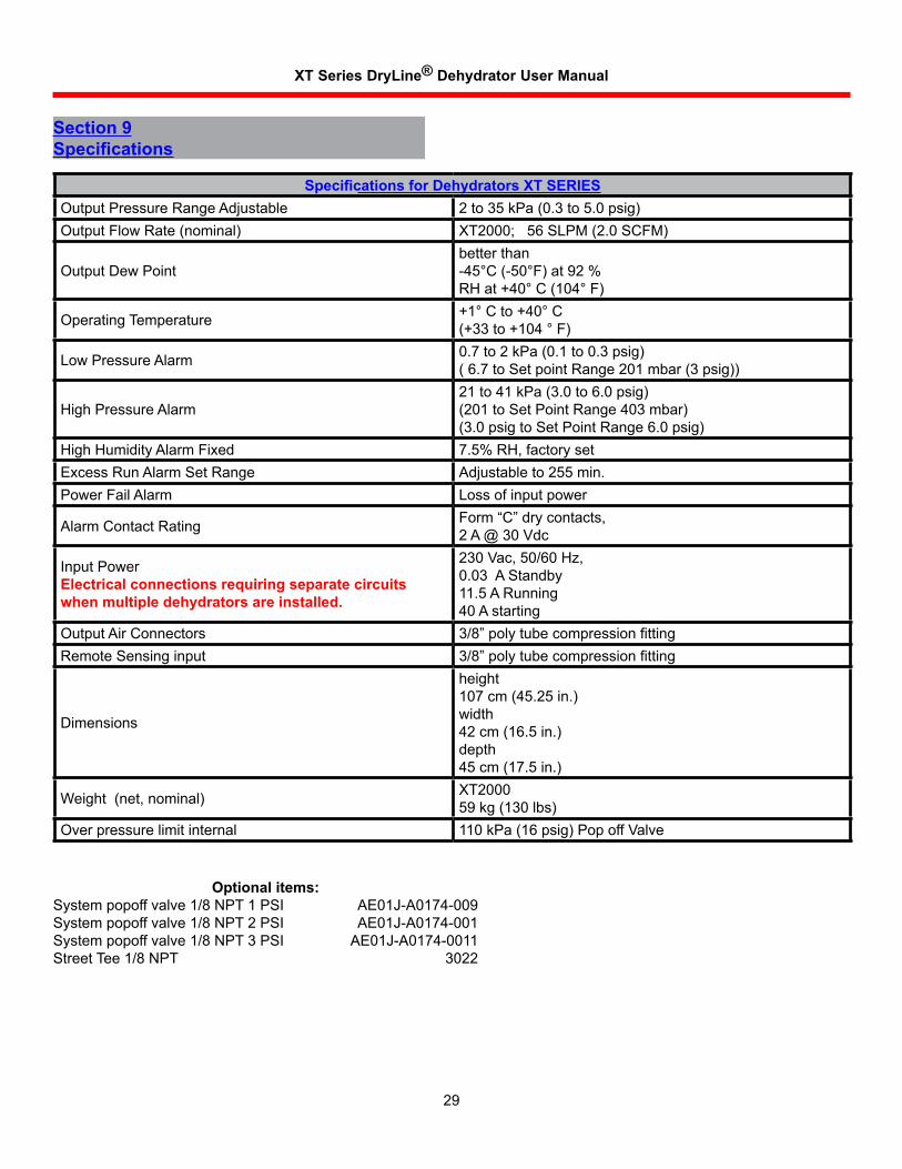
Optional items:Systempopoffvalve1/8NPT1PSI AE01J-A0174-009Systempopoffvalve1/8NPT2PSI AE01J-A0174-001Systempopoffvalve1/8NPT3PSI AE01J-A0174-0011StreetTee1/8NPT 3022
Specifications for Dehydrators XT SERIESOutputPressureRangeAdjustable 2to35kPa(0.3to5.0psig)OutputFlowRate(nominal) XT2000; 56 SLPM (2.0 SCFM)
OutputDewPointbetterthan-45°C(-50°F)at92%RHat+40°C(104°F)
OperatingTemperature +1°Cto+40°C(+33to+104°F)
LowPressureAlarm 0.7to2kPa(0.1to0.3psig)(6.7toSetpointRange201mbar(3psig))
HighPressureAlarm21to41kPa(3.0to6.0psig)(201toSetPointRange403mbar)(3.0psigtoSetPointRange6.0psig)
HighHumidityAlarmFixed 7.5%RH,factorysetExcessRunAlarmSetRange Adjustableto255min.PowerFailAlarm Lossofinputpower
AlarmContactRating Form “C” dry contacts,2A@30Vdc
InputPowerElectrical connections requiring separate circuits when multiple dehydrators are installed.
230Vac,50/60Hz,0.03AStandby11.5ARunning40Astarting
OutputAirConnectors 3/8” poly tube compression fittingRemoteSensinginput 3/8” poly tube compression fitting
Dimensions
height107cm(45.25in.)width42cm(16.5in.)depth45cm(17.5in.)
Weight(net,nominal) XT200059kg(130lbs)
Overpressurelimitinternal 110kPa(16psig)PopoffValve
XT Series DryLine® Dehydrator User Manual
30
Section 10Customer Support10.1 24 Hour Technical Service Hotline
AndrewmaintainsaTechnicalServiceHotlineforassistancewithproductrepairsandservice.
AndrewCorporation ACommScopeCompany 3WestbrookCorporateCenter,Suite900 Westchester,IL60154USA
From North America Telephone:1-800-255-1479 Fax(U.S.A.):1-800-349-5444
International Telephone:+1-779-435-6500 FaxNumber:+1-779-435-8579
Web Access Internet:www.commscope.com
http://www.commscope.com/andrew/eng/product/antennas/ter_microwave/pressurization/index.html
Email:#[email protected]
10.2 Free Loaner Program
Andrewmaintainsarepaircenterforpressurizationequipment.FreeloanerunitsareavailableforusewhileyourequipmentisbeingrepairedbyAndrew.CallourTechnicalServiceHotlinefordetails.
XT Series DryLine® Dehydrator User Manual
31
© 2008 CommScope, Inc. All rights reserved. (9/08) Rev: C
Andrew Corporation
XT Series Large Capacity DryLine®
Dehydrator System Three Year Limited Warranty
Seller warrants that any Andrew XT2000 type DryLine® Dehydrator is transferred rightfully and with good title; that it is free from any lawful security interest or other lien or encumbrance unknown to Buyer; and that for a period of thirty-six months (36) months from the date of installation or 3000 hours of actual run time (except for the compressor which is for a period of twelve (12) months or 1000 hours), whichever shall occur first, such equipment will be free from defects in material and workmanship which arise under proper and normal use and service. Buyer's exclusive remedy hereunder is limited to Seller's correction (either at its plant or at such other place as may be agreed upon between Seller and Buyer) of any such defects by repair or replacement at no cost to the Buyer; provided that the cost of any transportation in connection with the return of the equipment for the purpose of repair or replacement shall be borne by Buyer. Expressly excluded from the terms of this warranty are defects caused by: (i) faulty installation, (ii) lack of proper inspection or maintenance, (iii) and usage not in accordance with published ratings, specifications, or instructions. The provisions of this warranty shall be applicable with respect to any equipment Seller repairs or replaces pursuant to it.
SELLER MAKES NO WARRANTY, EXPRESS OR IMPLIED, OTHER THAN AS SPECIFICALLY STATED ABOVE. EXPRESSLY EXCLUDED ARE ANY IMPLIED WARRANTIES OF MERCHANTABILITY OR FITNESS FOR PURPOSE. THE FOREGOING SHALL CONSTITUTE ALL OF SELLER'S LIABILITY (EXCEPT AS TO PATENT INFRINGEMENT) WITH RESPECT TO THE EQUIPMENT. IN NO EVENT SHALL SELLER BE LIABLE FOR SPECIAL, CONSEQUENTIAL OR INCIDENTAL DAMAGES, INSTALLATION COSTS, LOST REVENUE OR PROFITS, OR ANY OTHER COSTS OF ANY NATURE AS A RESULT OF THE USE OF EQUIPMENT MANUFACTURED BY THE SELLER, WHETHER USED IN ACCORDANCE WITH INSTRUCTIONS OR NOT. UNDER NO CIRCUMSTANCES SHALL SELLER'S LIABILITY TO BUYER EXCEED THE ACTUAL SALES PRICE OF THE EQUIPMENT PROVIDED HEREUNDER. No representative is authorized to assume for Seller any other liability in connection with the equipment.

XT Series DryLine® Dehydrator User Manual
Recommended