ZERO A RIFLE COMBAT OPTIC (RCO) TO A SERVICE RIFLE
1
OVERVIEW • ELEMENTS OF ZEROING
• RCO SIGHTING SYSTEM / WINDAGE & ELEVATION
RULES
• ZEROING PROCEDURES
• FACTORS AFFECTING A ZERO
• TABLE 1A COURSE OF FIRE
2

TERMINAL LEARNING OBJECTIVE
Given a service rifle, Rifle Combat Optic (RCO), load bearing vest, magazine pouch, sling, (2) magazines, cleaning gear, ammunition, and a target, zero a Rifle Combat Optic (RCO) to a service rifle to ensure Point of Aim (POA) equals Point of Impact (POI) at 100 meters.
3

ENABLING LEARNING OBJECTIVES
• Given a service rifle, Rifle Combat Optic (RCO), load bearing vest, magazine pouch, common weapon sling, (2) magazines, cleaning gear, ammunition, and a target, mount and understand the elements necessary to establish a sound zero in accordance with MCRP 3-01A.
• Given a service rifle, Rifle Combat Optic (RCO), load bearing vest, magazine pouch, common weapon sling, (2) magazines, cleaning gear, ammunition, and a target, understand the RCO sighting system in accordance with MCRP 3-01A.
4

ENABLING LEARNING OBJECTIVES
• Given a service rifle, Rifle Combat Optic (RCO), load bearing vest, magazine pouch, common weapon sling, (2) magazines, cleaning gear, ammunition, and a target, establish pre-zero sight settings with the service rifle in accordance with MCRP 3-01A.
• Given a service rifle, Rifle Combat Optic (RCO), load bearing vest, magazine pouch, common weapon sling, (2) magazines, cleaning gear, ammunition, and a target, understand the factors affecting a zero in accordance with MCRP 3-01A.
5

• Method/Media
• Evaluation
• Safety/Cease Training
• Admin Notes
6
?
What I will Be
Teaching???
How I will Be
Teaching???
How You will Be
Evaluated???
MOUNTING AND UNDERSTANDING THE ELEMENTS TO ESTABLISH A SOUND ZERO
• Definition of a Zero A zero is the elevation and windage settings required to place a single shot, or the center of a shot group, in a pre-designated location on a target at 100 yards/meters, from a specific firing position, under ideal weather conditions (i.e., no wind).
• Line of sight Line of sight is a straight line beginning at the center of the eye, passing through the center of the optic to the point of aim on the target.

9

THE RCO SIGHTING SYSTEM/WINDAGE AND ELEVATION RULES
• The RCO Sighting System
The RCO is optically centered when it leaves the manufacturer. Windage and elevation adjusters are used to zero the optic. The adjusters can be moved with a coin, bladed screwdriver, or the extractor rim of the 5.56mm casing.
• Dimensions for Zeroing the RCO (a) ‘5V’ ring is 4 inches in diameter. (b) The round, black bull's-eye is 12 inches in diameter. (c) The 4-ring is 24 inches in diameter. (d) The 3-ring is 36 inches in diameter.
10

11

FRONT SIGHT:
• TO RAISE, TURN CLOCKWISE
• TO LOWER, TURN COUNTER CLOCKWISE
RI RCO ADJUSTERS SM – FRONT SIGHT POST
Windage Adjuster Elevation Adjuster
12

ZEROING PROCEDURES
• Pre Zero Sight Settings Pre-zeroing can be accomplished with a small arms collimator (SAC).
• Zeroing Zeroing the RCO is conducted at 100 meters/ yards. A zero is not established by simply getting a pre-zero sight setting.
13

ZEROING PROCEDURES
• Place a suitable target with an aiming point 4 inches in diameter contrasting with the background at a range of 100 meters and determine an aiming point.
• Fire five rounds to obtain a shot group in a time limit of 60 seconds.
• Triangulate the shot group to identify the center.
• Make horizontal and vertical adjustments using the windage and elevation knobs on the RCO.
14

15

SMALL ARMS COLLIMATOR
16

17

CONFIRM THE ZERO OF THE SERVICE RIFLE AT 100 METERS
ZEROING
18

FACTORS AFFECTING A ZERO
• Factors
-Placement of support hand
-Placement of the rifle buttstock in the pocket of the shoulder
-Grip of the firing hand
- Firing-side elbow
-Stock weld
19

FACTORS AFFECTING A ZERO
• Factors
-Eye relief -Sight picture -Muscular control -Breathing -Trigger control
20

TABLE 1A COURSE OF FIRE (TRAINING)
21
Distance
Target
Time (min)
Rounds
Position
Hold Confirma- tion
200
“A”
1
3
Sitting
200 “A” 1 3 Sitting
200 “A” 1 4 Sitting
Drill
Time (min)
Distance
Target
Rounds
Position
Stage One
Slow Fire
25
200 “A” 5 Sitting
200 “A” 5 Kneeling
200 “A” 5 Standing
200 “A” 5 Choice of Above
Stage Two
Rapid Fire
1
200
“D”
10
Standing to Sitting
1
200
“D”
10
Standing to Sitting
Stage Three
Slow Fire
5
300
“A”
5
Sitting
Stage Four
Rapid Fire
1
300
“D”
10
Standing to Prone
1
300
“D”
10
Standing to Prone
Stage Five
Slow Fire
15
500
“B- MOD” 15
Prone
Total 90

TABLE 1A COURSE OF FIRE (EVALUATION)
22
Drill
Time (min)
Distance
Target
Rounds
Position
Stage One
Slow Fire
20
200 “A” 5 Sitting
200 “A” 5 Kneeling
200 “A” 5 Standing
Stage Two
Rapid Fire
1
200
“D”
10
Standing to Sitting
Stage Three
Slow Fire
5
300
“A”
5
Sitting
Stage Four
Rapid Fire
1
300
“D”
10
Standing to Prone
Stage Five
Slow Fire
10
500
“B- MOD” 10
Prone
Total 60
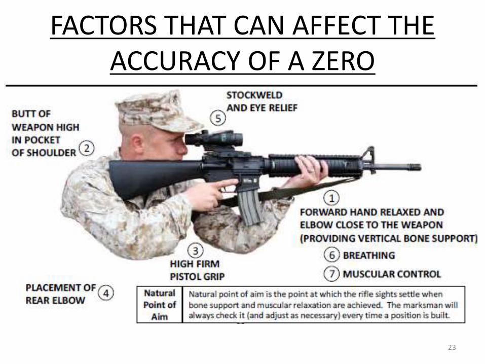
FACTORS THAT CAN AFFECT THE ACCURACY OF A ZERO
23

SUMMARY • ELEMENTS OF ZEROING
• RCO SIGHTING SYSTEM / WINDAGE & ELEVATION
RULES
• ZEROING PROCEDURES
• FACTORS AFFECTING A ZERO
• TABLE 1A COURSE OF FIRE
24
Recommended