Embed Size (px)
Citation preview
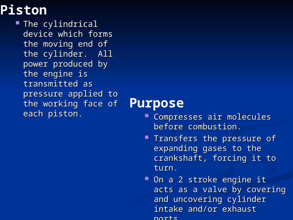
The cylindrical The cylindrical device which forms device which forms the moving end of the moving end of the cylinder. All the cylinder. All power produced by power produced by the engine is the engine is transmitted as transmitted as pressure applied to pressure applied to the working face of the working face of each piston.each piston.
Piston
Compresses air molecules before Compresses air molecules before combustion.combustion.
Transfers the pressure of Transfers the pressure of expanding gases to the expanding gases to the crankshaft, forcing it to turn.crankshaft, forcing it to turn.
On a 2 stroke engine it acts as a On a 2 stroke engine it acts as a valve by covering and valve by covering and uncovering cylinder intake uncovering cylinder intake and/or exhaust ports.and/or exhaust ports.
LocationLocation Inside each cylinderInside each cylinder
Purpose
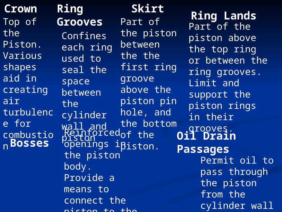
Top of the Piston.Various shapes aid in creating air turbulence for combustion
Confines each ring used to seal the space between the cylinder wall and piston
Crown Ring Grooves Ring Lands
Skirt
Bosses
Part of the piston above the top ring or between the ring grooves. Limit and support the piston rings in their grooves.
Oil Drain Passages
Permit oil to pass through the piston from the cylinder wall into the crankcase.
Part of the piston between the the first ring groove above the piston pin hole, and the bottom of the piston.Reinforced
openings in the piston body. Provide a means to connect the piston to the connecting rod.
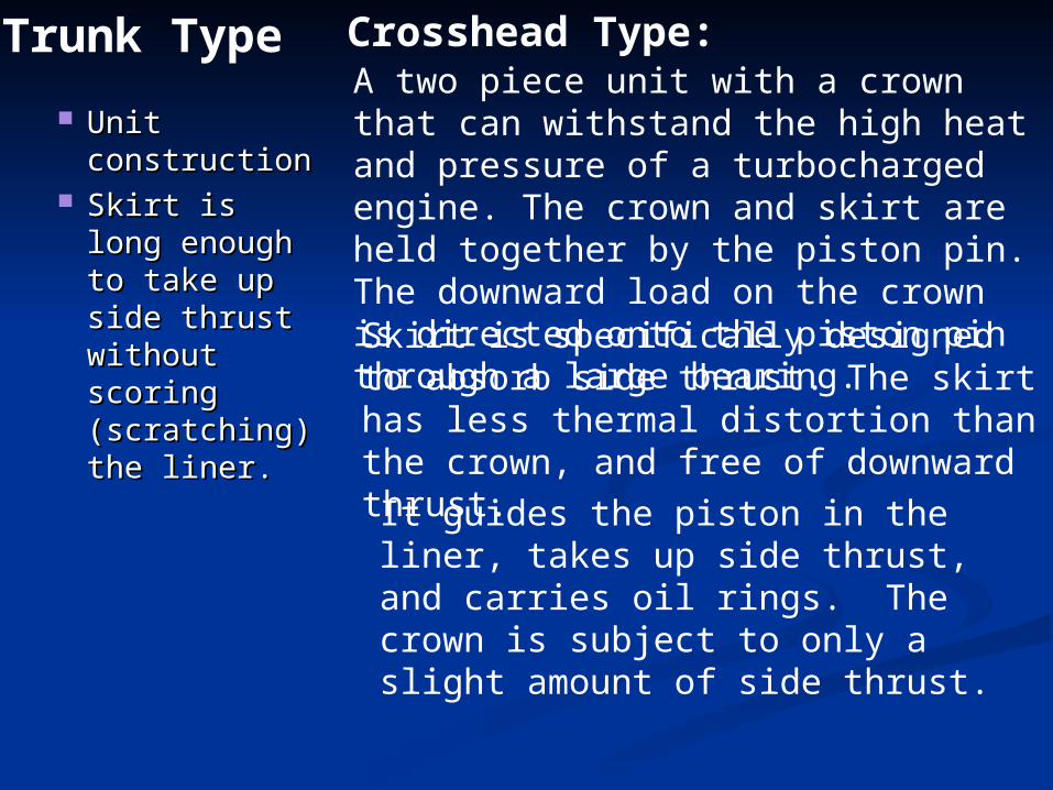
Unit Unit constructionconstruction
Skirt is long Skirt is long enough to enough to take up side take up side thrust thrust without without scoring scoring (scratching) (scratching) the liner.the liner.
Trunk TypeA two piece unit with a crown that can withstand the high heat and pressure of a turbocharged engine. The crown and skirt are held together by the piston pin. The downward load on the crown is directed onto the piston pin through a large bearing.
Crosshead Type:
Skirt is specifically designed to absorb side thrust. The skirt has less thermal distortion than the crown, and free of downward thrust.
It guides the piston in the liner, takes up side thrust, and carries oil rings. The crown is subject to only a slight amount of side thrust.
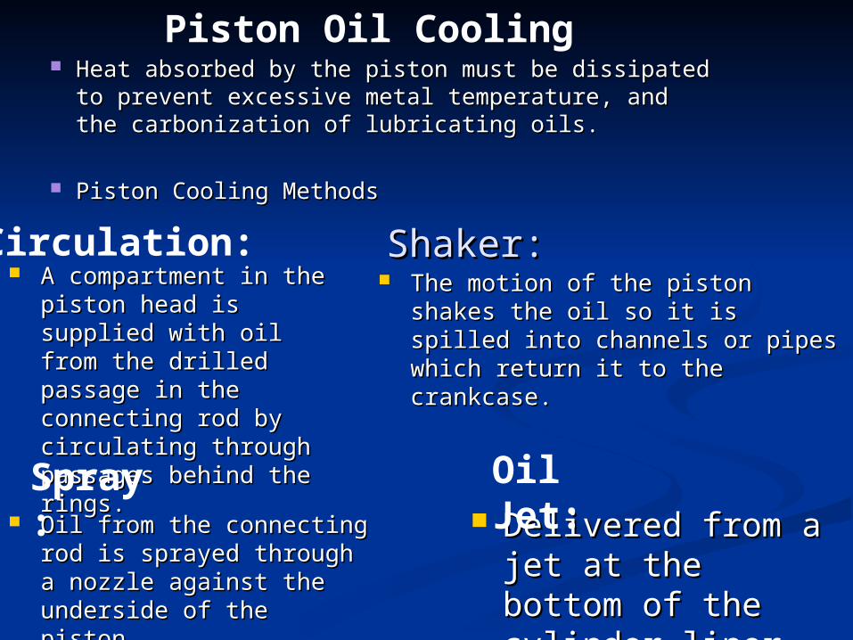
Heat absorbed by the piston must be dissipated to Heat absorbed by the piston must be dissipated to prevent excessive metal temperature, and the prevent excessive metal temperature, and the carbonization of lubricating oils.carbonization of lubricating oils.
Piston Cooling MethodsPiston Cooling Methods
Piston Oil Cooling
A compartment in the A compartment in the piston head is supplied piston head is supplied with oil from the drilled with oil from the drilled passage in the passage in the connecting rod by connecting rod by circulating through circulating through passages behind the passages behind the rings.rings.
Circulation: The motion of the piston shakes the The motion of the piston shakes the
oil so it is spilled into channels or oil so it is spilled into channels or pipes which return it to the pipes which return it to the crankcase.crankcase.
Shaker:Shaker:
Oil from the connecting rod Oil from the connecting rod is sprayed through a is sprayed through a nozzle against the nozzle against the underside of the piston.underside of the piston.
Spray: Delivered from a Delivered from a
jet at the bottom of jet at the bottom of the cylinder liner.the cylinder liner.
Oil Jet:
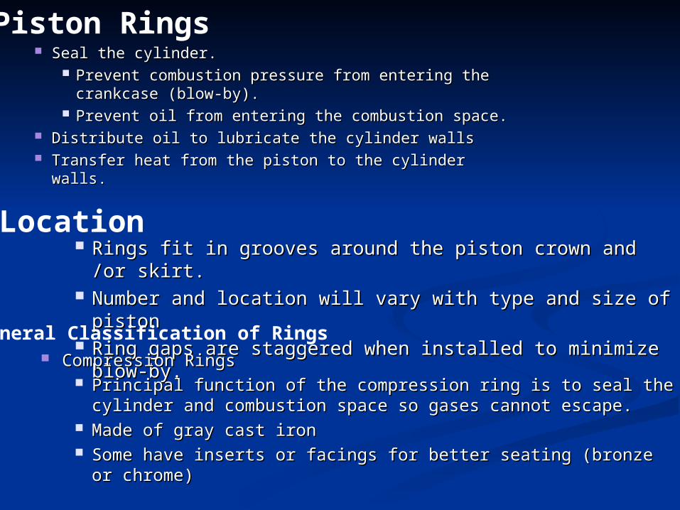
Seal the cylinder.Seal the cylinder. Prevent combustion pressure from entering the Prevent combustion pressure from entering the
crankcase (blow-by).crankcase (blow-by). Prevent oil from entering the combustion space.Prevent oil from entering the combustion space.
Distribute oil to lubricate the cylinder wallsDistribute oil to lubricate the cylinder walls Transfer heat from the piston to the cylinder walls.Transfer heat from the piston to the cylinder walls.
Piston Rings
Rings fit in grooves around the piston crown and /or skirt.Rings fit in grooves around the piston crown and /or skirt. Number and location will vary with type and size of pistonNumber and location will vary with type and size of piston Ring gaps are staggered when installed to minimize blow-by.Ring gaps are staggered when installed to minimize blow-by.
Location
General Classification of Rings Compression RingsCompression Rings
Principal function of the compression ring is to seal the cylinder and Principal function of the compression ring is to seal the cylinder and combustion space so gases cannot escape.combustion space so gases cannot escape.
Made of gray cast ironMade of gray cast iron Some have inserts or facings for better seating (bronze or chrome)Some have inserts or facings for better seating (bronze or chrome)
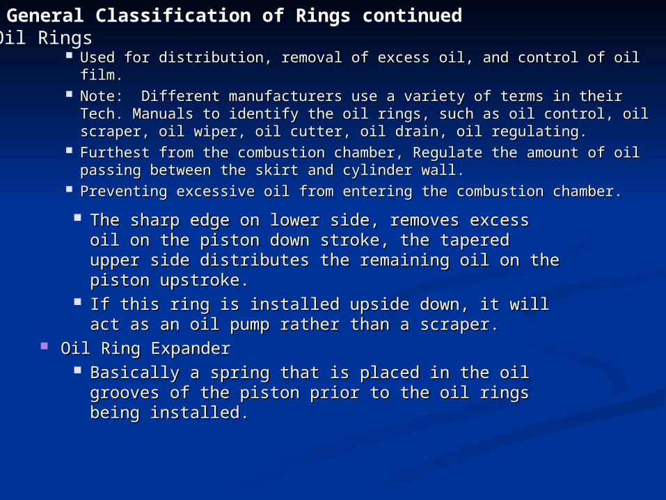
Used for distribution, removal of excess oil, and control of oil film.Used for distribution, removal of excess oil, and control of oil film. Note: Different manufacturers use a variety of terms in their Tech. Note: Different manufacturers use a variety of terms in their Tech.
Manuals to identify the oil rings, such as oil control, oil scraper, oil Manuals to identify the oil rings, such as oil control, oil scraper, oil wiper, oil cutter, oil drain, oil regulating.wiper, oil cutter, oil drain, oil regulating.
Furthest from the combustion chamber, Regulate the amount of oil Furthest from the combustion chamber, Regulate the amount of oil passing between the skirt and cylinder wall.passing between the skirt and cylinder wall.
Preventing excessive oil from entering the combustion chamber.Preventing excessive oil from entering the combustion chamber.
Oil RingsGeneral Classification of Rings continued
The sharp edge on lower side, removes excess oil on The sharp edge on lower side, removes excess oil on the piston down stroke, the tapered upper side the piston down stroke, the tapered upper side distributes the remaining oil on the piston upstroke.distributes the remaining oil on the piston upstroke.
If this ring is installed upside down, it will act as an oil If this ring is installed upside down, it will act as an oil pump rather than a scraper.pump rather than a scraper.
Oil Ring ExpanderOil Ring Expander Basically a spring that is placed in the oil grooves of the Basically a spring that is placed in the oil grooves of the
piston prior to the oil rings being installed.piston prior to the oil rings being installed.
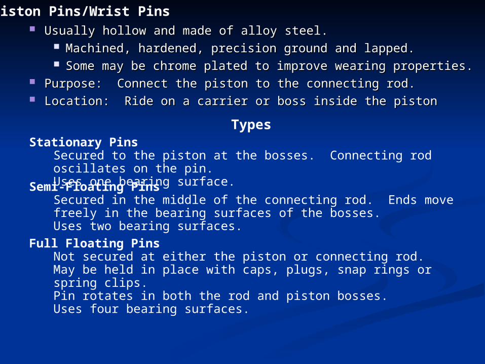
Usually hollow and made of alloy steel.Usually hollow and made of alloy steel. Machined, hardened, precision ground and lapped.Machined, hardened, precision ground and lapped. Some may be chrome plated to improve wearing properties.Some may be chrome plated to improve wearing properties.
Purpose: Connect the piston to the connecting rod.Purpose: Connect the piston to the connecting rod. Location: Ride on a carrier or boss inside the pistonLocation: Ride on a carrier or boss inside the piston
Piston Pins/Wrist Pins
TypesStationary Pins
Secured to the piston at the bosses. Connecting rod oscillates on the pin.Uses one bearing surface.Semi-Floating PinsSecured in the middle of the connecting rod. Ends move freely in the bearing surfaces of the bosses.Uses two bearing surfaces.
Full Floating PinsNot secured at either the piston or connecting rod.May be held in place with caps, plugs, snap rings or spring clips.Pin rotates in both the rod and piston bosses.Uses four bearing surfaces.
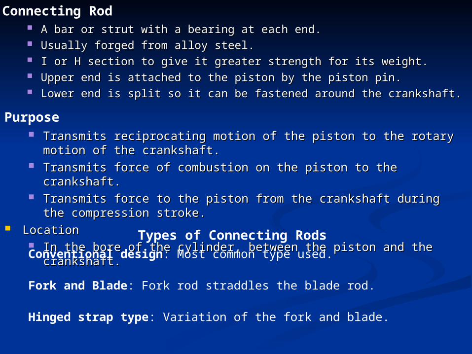
A bar or strut with a bearing at each end.A bar or strut with a bearing at each end. Usually forged from alloy steel.Usually forged from alloy steel. I or H section to give it greater strength for its weight.I or H section to give it greater strength for its weight. Upper end is attached to the piston by the piston pin.Upper end is attached to the piston by the piston pin. Lower end is split so it can be fastened around the crankshaft.Lower end is split so it can be fastened around the crankshaft.
Connecting Rod
Transmits reciprocating motion of the piston to the rotary motion of Transmits reciprocating motion of the piston to the rotary motion of the crankshaft.the crankshaft.
Transmits force of combustion on the piston to the crankshaft.Transmits force of combustion on the piston to the crankshaft. Transmits force to the piston from the crankshaft during the Transmits force to the piston from the crankshaft during the
compression stroke.compression stroke. LocationLocation
In the bore of the cylinder, between the piston and the crankshaft.In the bore of the cylinder, between the piston and the crankshaft.
Purpose
Types of Connecting RodsConventional design: Most common type used.
Fork and Blade: Fork rod straddles the blade rod.
Hinged strap type: Variation of the fork and blade.
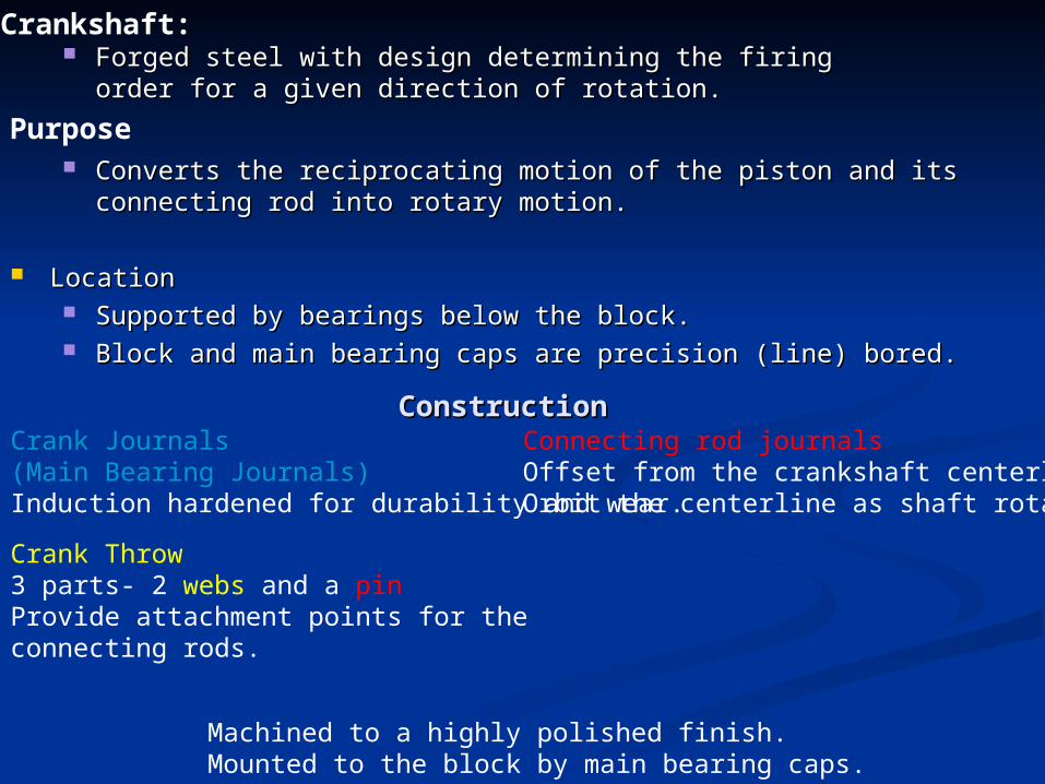
Forged steel with design determining the firing order for a Forged steel with design determining the firing order for a given direction of rotation.given direction of rotation.
Crankshaft:
Converts the reciprocating motion of the piston and its connecting rod Converts the reciprocating motion of the piston and its connecting rod into rotary motion.into rotary motion.
LocationLocation Supported by bearings below the block.Supported by bearings below the block. Block and main bearing caps are precision (line) bored.Block and main bearing caps are precision (line) bored.
Purpose
ConstructionConstructionCrank Journals(Main Bearing Journals)Induction hardened for durability and wear.
Connecting rod journalsOffset from the crankshaft centerlineOrbit the centerline as shaft rotates.
Machined to a highly polished finish.Mounted to the block by main bearing caps.
Crank Throw3 parts- 2 webs and a pinProvide attachment points for the connecting rods.
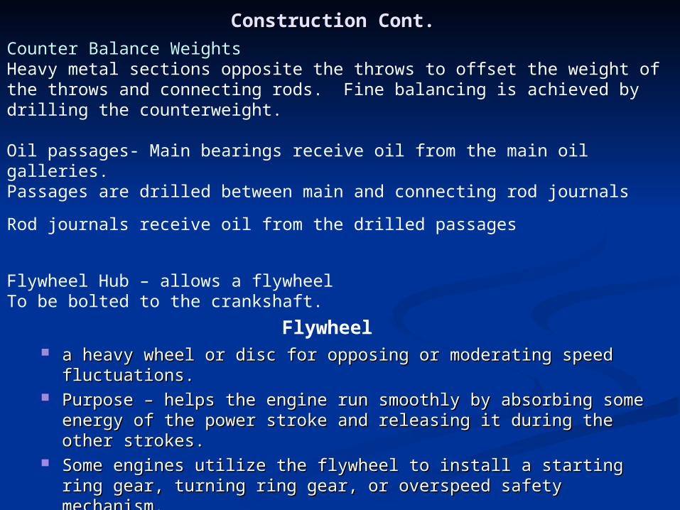
Counter Balance WeightsHeavy metal sections opposite the throws to offset the weight of the throws and connecting rods. Fine balancing is achieved by drilling the counterweight.
Construction Cont.Construction Cont.
Oil passages- Main bearings receive oil from the main oil galleries.Passages are drilled between main and connecting rod journals
Rod journals receive oil from the drilled passages
Flywheel Hub – allows a flywheelTo be bolted to the crankshaft.
Flywheel a heavy wheel or disc for opposing or moderating speed fluctuations.a heavy wheel or disc for opposing or moderating speed fluctuations. Purpose – helps the engine run smoothly by absorbing some energy of Purpose – helps the engine run smoothly by absorbing some energy of
the power stroke and releasing it during the other strokes.the power stroke and releasing it during the other strokes. Some engines utilize the flywheel to install a starting ring gear, turning Some engines utilize the flywheel to install a starting ring gear, turning
ring gear, or overspeed safety mechanism.ring gear, or overspeed safety mechanism. Location- firmly bolted to the hub of the crankshaft.Location- firmly bolted to the hub of the crankshaft.
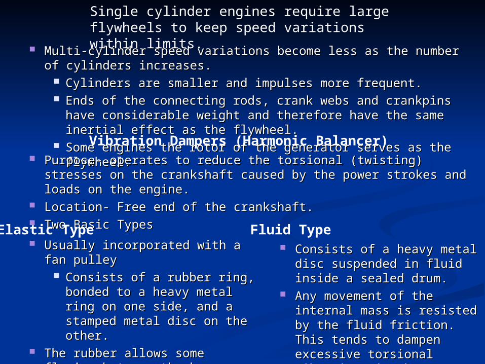
Multi-cylinder speed variations become less as the number of cylinders Multi-cylinder speed variations become less as the number of cylinders increases.increases.
Cylinders are smaller and impulses more frequent.Cylinders are smaller and impulses more frequent. Ends of the connecting rods, crank webs and crankpins have Ends of the connecting rods, crank webs and crankpins have
considerable weight and therefore have the same inertial effect as considerable weight and therefore have the same inertial effect as the flywheel.the flywheel.
Some engines the rotor of the generator serves as the flywheel.Some engines the rotor of the generator serves as the flywheel.
Single cylinder engines require large flywheels to keep speed variations within limits.
Vibration Dampers (Harmonic Balancer) Purpose- operates to reduce the torsional (twisting) stresses on the Purpose- operates to reduce the torsional (twisting) stresses on the
crankshaft caused by the power strokes and loads on the engine.crankshaft caused by the power strokes and loads on the engine. Location- Free end of the crankshaft.Location- Free end of the crankshaft. Two Basic TypesTwo Basic Types
Elastic Type Usually incorporated with a fan Usually incorporated with a fan
pulley pulley Consists of a rubber ring, Consists of a rubber ring,
bonded to a heavy metal ring bonded to a heavy metal ring on one side, and a stamped on one side, and a stamped metal disc on the other.metal disc on the other.
The rubber allows some flexing The rubber allows some flexing between the heavy ring and between the heavy ring and crankshaft to absorb vibration crankshaft to absorb vibration from the engine.from the engine.
Fluid Type Consists of a heavy metal disc Consists of a heavy metal disc
suspended in fluid inside a suspended in fluid inside a sealed drum.sealed drum.
Any movement of the internal Any movement of the internal mass is resisted by the fluid mass is resisted by the fluid friction. This tends to friction. This tends to dampen excessive torsional dampen excessive torsional vibrations in the crankshaft.vibrations in the crankshaft.
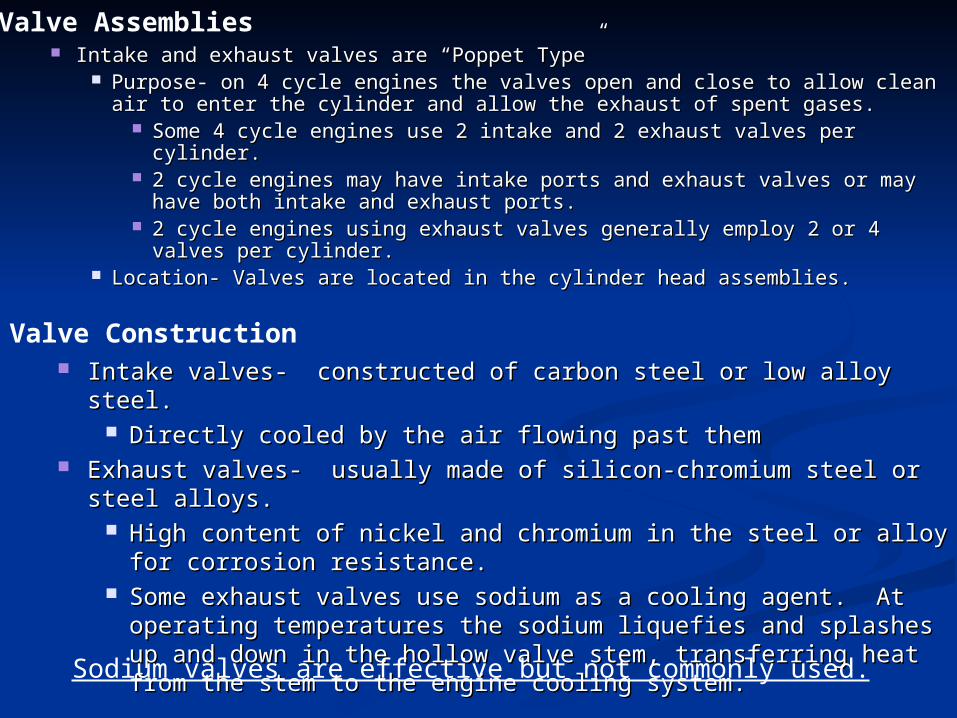
Intake and exhaust valves are “Poppet Type”Intake and exhaust valves are “Poppet Type” Purpose- on 4 cycle engines the valves open and close to allow clean air Purpose- on 4 cycle engines the valves open and close to allow clean air
to enter the cylinder and allow the exhaust of spent gases.to enter the cylinder and allow the exhaust of spent gases. Some 4 cycle engines use 2 intake and 2 exhaust valves per Some 4 cycle engines use 2 intake and 2 exhaust valves per
cylinder.cylinder. 2 cycle engines may have intake ports and exhaust valves or may 2 cycle engines may have intake ports and exhaust valves or may
have both intake and exhaust ports.have both intake and exhaust ports. 2 cycle engines using exhaust valves generally employ 2 or 4 valves 2 cycle engines using exhaust valves generally employ 2 or 4 valves
per cylinder.per cylinder. Location- Valves are located in the cylinder head assemblies.Location- Valves are located in the cylinder head assemblies.
Valve Assemblies
Intake valves- constructed of carbon steel or low alloy steel.Intake valves- constructed of carbon steel or low alloy steel. Directly cooled by the air flowing past themDirectly cooled by the air flowing past them
Exhaust valves- usually made of silicon-chromium steel or steel alloys.Exhaust valves- usually made of silicon-chromium steel or steel alloys. High content of nickel and chromium in the steel or alloy for High content of nickel and chromium in the steel or alloy for
corrosion resistance.corrosion resistance. Some exhaust valves use sodium as a cooling agent. At operating Some exhaust valves use sodium as a cooling agent. At operating
temperatures the sodium liquefies and splashes up and down in the temperatures the sodium liquefies and splashes up and down in the hollow valve stem, transferring heat from the stem to the engine hollow valve stem, transferring heat from the stem to the engine cooling system.cooling system.
Valve Construction
Sodium valves are effective but not commonly used.
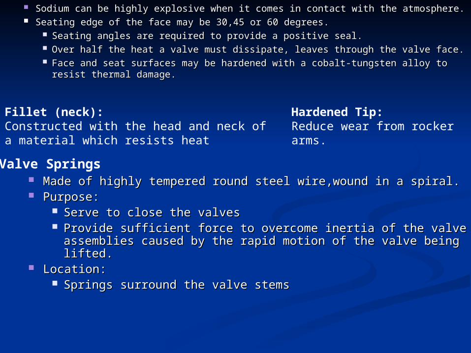
Sodium can be highly explosive when it comes in contact with the Sodium can be highly explosive when it comes in contact with the atmosphere.atmosphere.
Seating edge of the face may be 30,45 or 60 degrees.Seating edge of the face may be 30,45 or 60 degrees. Seating angles are required to provide a positive seal.Seating angles are required to provide a positive seal. Over half the heat a valve must dissipate, leaves through the valve face.Over half the heat a valve must dissipate, leaves through the valve face. Face and seat surfaces may be hardened with a cobalt-tungsten alloy to Face and seat surfaces may be hardened with a cobalt-tungsten alloy to
resist thermal damage.resist thermal damage.Fillet (neck):Constructed with the head and neck of a material which resists heat
Hardened Tip:Reduce wear from rocker arms.
Valve Springs Made of highly tempered round steel wire,wound in a spiral.Made of highly tempered round steel wire,wound in a spiral. Purpose:Purpose:
Serve to close the valvesServe to close the valves Provide sufficient force to overcome inertia of the valve assemblies Provide sufficient force to overcome inertia of the valve assemblies
caused by the rapid motion of the valve being lifted.caused by the rapid motion of the valve being lifted. Location:Location:
Springs surround the valve stemsSprings surround the valve stems
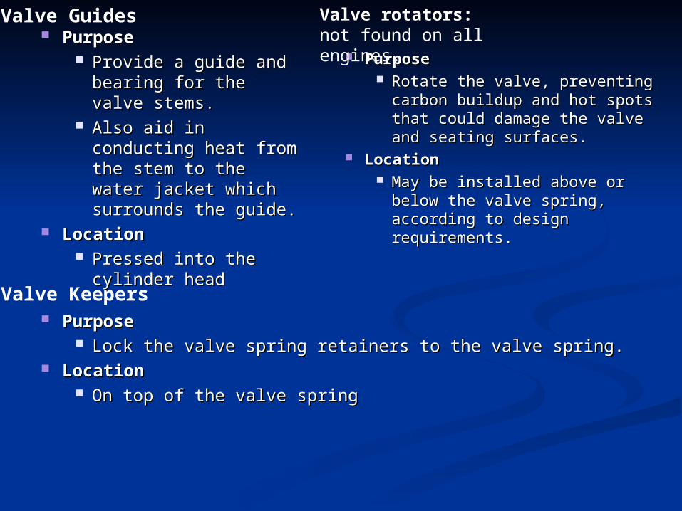
PurposePurpose Rotate the valve, preventing Rotate the valve, preventing
carbon buildup and hot spots carbon buildup and hot spots that could damage the valve that could damage the valve and seating surfaces.and seating surfaces.
LocationLocation May be installed above or below May be installed above or below
the valve spring, according to the valve spring, according to design requirements.design requirements.
Valve rotators:not found on all engines.
Valve Guides PurposePurpose
Provide a guide and Provide a guide and bearing for the valve bearing for the valve stems.stems.
Also aid in conducting Also aid in conducting heat from the stem to heat from the stem to the water jacket which the water jacket which surrounds the guide.surrounds the guide.
LocationLocation Pressed into the Pressed into the
cylinder headcylinder head
Valve Keepers PurposePurpose
Lock the valve spring retainers to the valve spring.Lock the valve spring retainers to the valve spring. LocationLocation
On top of the valve springOn top of the valve spring
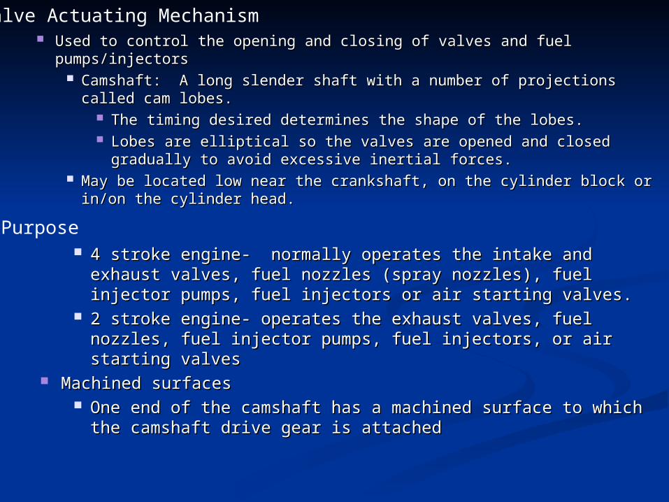
Used to control the opening and closing of valves and fuel pumps/injectorsUsed to control the opening and closing of valves and fuel pumps/injectors Camshaft: A long slender shaft with a number of projections called cam Camshaft: A long slender shaft with a number of projections called cam
lobes.lobes. The timing desired determines the shape of the lobes.The timing desired determines the shape of the lobes. Lobes are elliptical so the valves are opened and closed gradually to Lobes are elliptical so the valves are opened and closed gradually to
avoid excessive inertial forces.avoid excessive inertial forces. May be located low near the crankshaft, on the cylinder block or in/on May be located low near the crankshaft, on the cylinder block or in/on
the cylinder head.the cylinder head.
Valve Actuating Mechanism
Purpose 4 stroke engine- normally operates the intake and exhaust valves, 4 stroke engine- normally operates the intake and exhaust valves,
fuel nozzles (spray nozzles), fuel injector pumps, fuel injectors or fuel nozzles (spray nozzles), fuel injector pumps, fuel injectors or air starting valves.air starting valves.
2 stroke engine- operates the exhaust valves, fuel nozzles, fuel 2 stroke engine- operates the exhaust valves, fuel nozzles, fuel injector pumps, fuel injectors, or air starting valvesinjector pumps, fuel injectors, or air starting valves
Machined surfacesMachined surfaces One end of the camshaft has a machined surface to which the One end of the camshaft has a machined surface to which the
camshaft drive gear is attachedcamshaft drive gear is attached
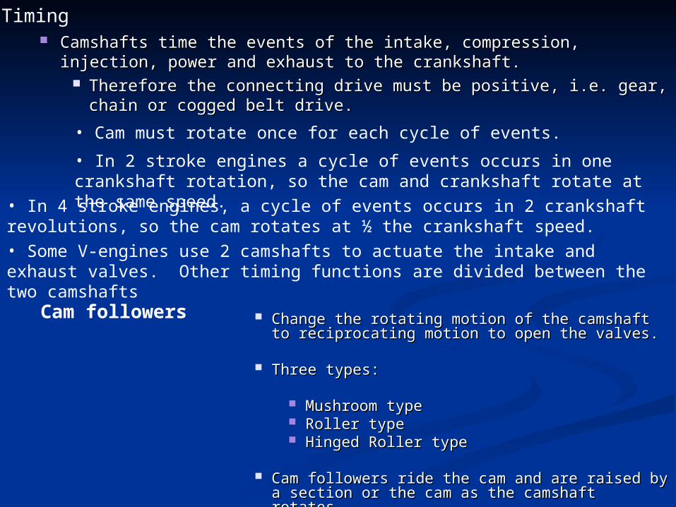
Camshafts time the events of the intake, compression, injection, power Camshafts time the events of the intake, compression, injection, power and exhaust to the crankshaft.and exhaust to the crankshaft.
Therefore the connecting drive must be positive, i.e. gear, chain or Therefore the connecting drive must be positive, i.e. gear, chain or cogged belt drive.cogged belt drive.
Timing
• In 4 stroke engines, a cycle of events occurs in 2 crankshaft revolutions, so the cam rotates at ½ the crankshaft speed.
• Cam must rotate once for each cycle of events.
• In 2 stroke engines a cycle of events occurs in one crankshaft rotation, so the cam and crankshaft rotate at the same speed.
• Some V-engines use 2 camshafts to actuate the intake and exhaust valves. Other timing functions are divided between the two camshafts
Cam followers Change the rotating motion of the camshaft to Change the rotating motion of the camshaft to reciprocating motion to open the valves.reciprocating motion to open the valves.
Three types:Three types:
Mushroom typeMushroom type Roller typeRoller type Hinged Roller typeHinged Roller type
Cam followers ride the cam and are raised by a Cam followers ride the cam and are raised by a section or the cam as the camshaft rotates.section or the cam as the camshaft rotates.
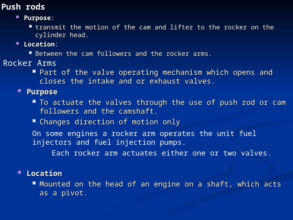
PurposePurpose:: transmit the motion of the cam and lifter to the rocker on the cylinder head.transmit the motion of the cam and lifter to the rocker on the cylinder head.
LocationLocation:: Between the cam followers and the rocker arms.Between the cam followers and the rocker arms.
Push rods
Part of the valve operating mechanism which opens and closes the Part of the valve operating mechanism which opens and closes the intake and or exhaust valves.intake and or exhaust valves.
PurposePurpose To actuate the valves through the use of push rod or cam followers To actuate the valves through the use of push rod or cam followers
and the camshaft.and the camshaft. Changes direction of motion onlyChanges direction of motion only
Rocker Arms
On some engines a rocker arm operates the unit fuel injectors and fuel injection pumps.
Each rocker arm actuates either one or two valves.
LocationLocation Mounted on the head of an engine on a shaft, which acts as a pivot.Mounted on the head of an engine on a shaft, which acts as a pivot.
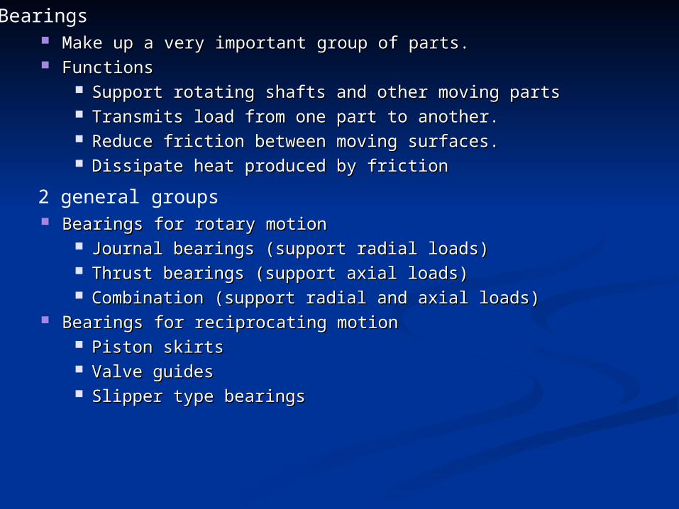
Make up a very important group of parts.Make up a very important group of parts. FunctionsFunctions
Support rotating shafts and other moving partsSupport rotating shafts and other moving parts Transmits load from one part to another.Transmits load from one part to another. Reduce friction between moving surfaces.Reduce friction between moving surfaces. Dissipate heat produced by frictionDissipate heat produced by friction
Bearings
2 general groups Bearings for rotary motionBearings for rotary motion
Journal bearings (support radial loads)Journal bearings (support radial loads) Thrust bearings (support axial loads)Thrust bearings (support axial loads) Combination (support radial and axial loads)Combination (support radial and axial loads)
Bearings for reciprocating motionBearings for reciprocating motion Piston skirtsPiston skirts Valve guidesValve guides Slipper type bearingsSlipper type bearings
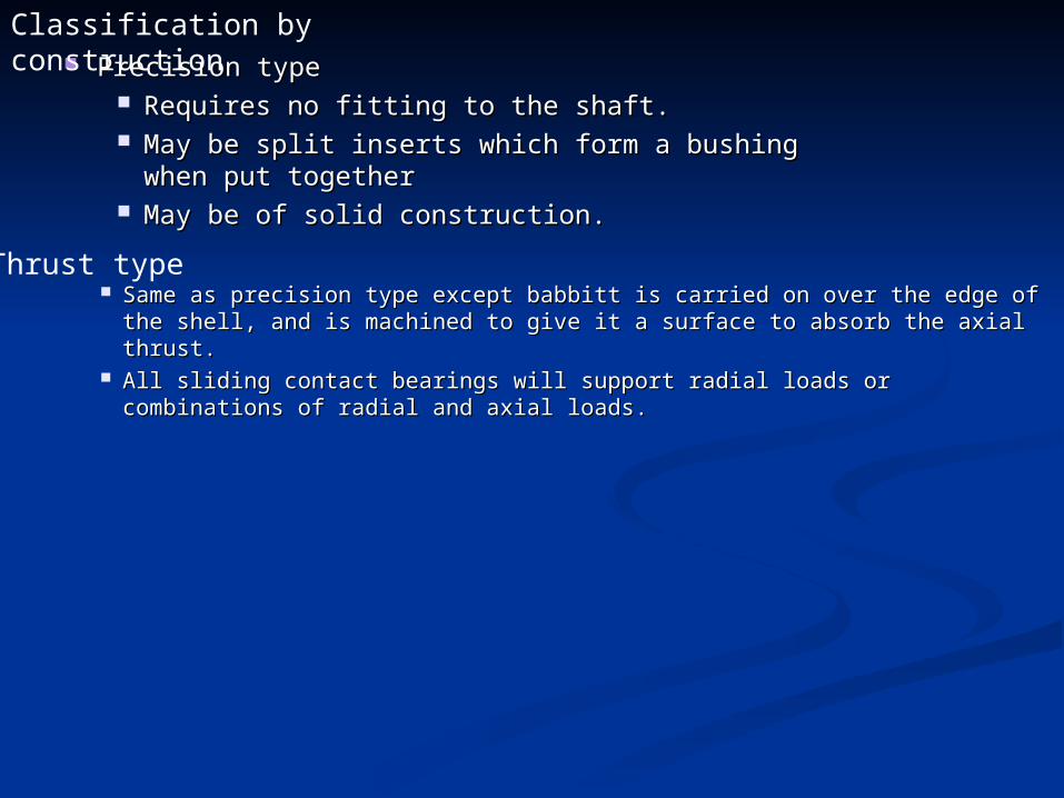
Precision typePrecision type Requires no fitting to the shaft.Requires no fitting to the shaft. May be split inserts which form a bushing when May be split inserts which form a bushing when
put togetherput together May be of solid construction.May be of solid construction.
Classification by construction
Thrust type Same as precision type except babbitt is carried on over the edge of the Same as precision type except babbitt is carried on over the edge of the
shell, and is machined to give it a surface to absorb the axial thrust.shell, and is machined to give it a surface to absorb the axial thrust. All sliding contact bearings will support radial loads or combinations of All sliding contact bearings will support radial loads or combinations of
radial and axial loads.radial and axial loads.
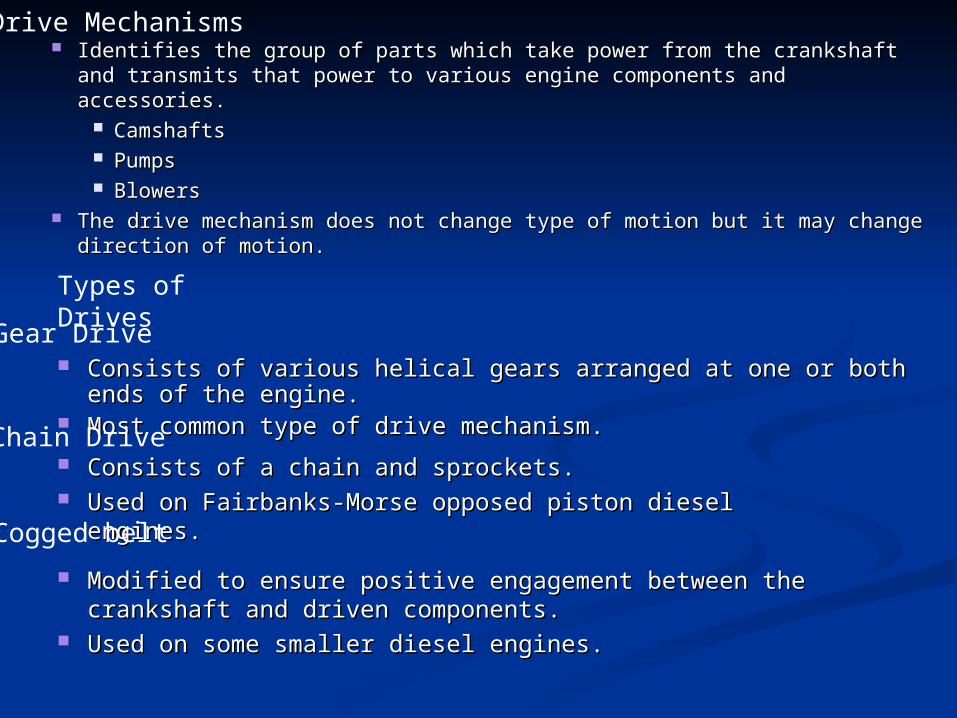
Identifies the group of parts which take power from the crankshaft and Identifies the group of parts which take power from the crankshaft and transmits that power to various engine components and accessories.transmits that power to various engine components and accessories.
CamshaftsCamshafts PumpsPumps BlowersBlowers
The drive mechanism does not change type of motion but it may The drive mechanism does not change type of motion but it may change direction of motion.change direction of motion.
Drive Mechanisms
Types of Drives
Gear Drive Consists of various helical gears arranged at one or both ends of the Consists of various helical gears arranged at one or both ends of the
engine.engine. Most common type of drive mechanism.Most common type of drive mechanism.Chain Drive Consists of a chain and sprockets.Consists of a chain and sprockets. Used on Fairbanks-Morse opposed piston diesel engines.Used on Fairbanks-Morse opposed piston diesel engines.
Cogged belt
Modified to ensure positive engagement between the crankshaft and Modified to ensure positive engagement between the crankshaft and driven components.driven components.
Used on some smaller diesel engines.Used on some smaller diesel engines.


![Advanced Petroleum Based Fuels- Diesel Emission Control ...0.08 0.10 NOx [g/mile] 0.0 0.2 0.4 0.6 0.8 1.0 1.2 1.4 Diesel Future II: Advanced Engine Control & Advanced Aftertreatment](https://img.pdfslide.net/doc/110x75/60add80358b89e583c36e4f2/advanced-petroleum-based-fuels-diesel-emission-control-008-010-nox-gmile.jpg)


![DIESEL - MX17 - Autodata MAX/DIESEL.pdfinjectors value classification, speed limit alfa romeo obd ii can alfa romeo x x - alfa romeo ... [tdi pd] - a2 1.4 [tdi pd] bosch edc 15p (diesel](https://img.pdfslide.net/doc/110x75/5a9ec8c17f8b9a84178bd532/pdfdiesel-mx17-maxdieselpdfinjectors-value-classification-speed-limit-alfa.jpg)