Embed Size (px)
Citation preview
A. M. Elbaz, Mohy Mansour, Khaled A. Elsayed & Diaaeldin Mohamed
International Journal of Applied Sciences (IJAS), Volume (4) : Issue (1) : 2013 9
An Experimental Study of the Effect of Partial Premixing Level on the Interaction between the Flame Kernel and Flow Field
A. M. Elbaz [email protected] Faculty of Engineering/Mechanical Power Engineering Department, Helwan University Cairo, 11718, Egypt
Mohy Mansour [email protected] Faculty of Engineering/Mechanical Power Engineering Department, Cairo University Cairo, Egypt
Khaled A. Elsayed [email protected] Faculty of Science/Physics Department, Cairo University Cairo, Egypt
Diaaeldin Mohamed [email protected] Faculty of Engineering/Mechanical Power Engineering Department, Cairo University Cairo, Egypt
Abstract
Flame kernels in spark-ignited combustion systems dominate the flame propagation and
combustion stability, performance and emissions. The aim of the present work is to investigate
the flow field associated with flame kernel propagation history in partial premixing natural gas
turbulent flames. The main parameters under investigation are the degree of partial premixing
and jet velocity. Three different degrees of partial premixing and five values of jet velocity
between10 and 20 m/s have been selected for the present work at an equivalence ratio of 2. The
mean flow field and turbulence intensity are measured using two-dimensional Planar Imaging
Velocimetry (PIV). A pulsed Nd: YAG laser is used for flame ignition. The turbulent flow field is
captured after the ignition at several time intervals between, 150, and 2500 µs after ignition. The
results show that the flame kernel does not show any significant effect on the scale of mean flow
field. On the other hand, the flame kernel increases the global turbulence intensity in flames in
comparison with the isothermal cases. The flame kernel propagation is associated with a steep
increase in the centerline turbulence intensity of the jet flow. An increase in the degree of partial
premixing and/or the jet velocity increases the centerline turbulence intensity accompanying the
flame kernel propagation. This leads to break-up of the degree of partial premixing of the flame
structure, and hence, decreased flame stability. Also, the higher the degree of partial premixing
or the higher the jet velocity leads to more rapid flame kernel extinction. The results show that the
rate of flame kernel propagation is very fast at the early stage of the kernel propagation up to the
first 300 µs and then it slows down afterwards.
Keywords: Flame Kernel, Partial Premixed Flame, PIV, Flow Field.
A. M. Elbaz, Mohy Mansour, Khaled A. Elsayed & Diaaeldin Mohamed
International Journal of Applied Sciences (IJAS), Volume (4) : Issue (1) : 2013 10
1. INTRODUCTION
The early phase of combustion in spark ignited combustion systems affects the flame propagation and stability, and hence the performance, of the combustion process and the system efficiency. The developing flame kernel represents this phase and is affected by many parameters, such as spark energy, rate of energy release, turbulent flow field and the fuel/ air mixing. Previous studies have shown that variations in the initial growth of the flame kernel contribute significantly to cycle-to-cycle variation in engine performance and emissions [1]. The flame kernel has attracted many experimental research groups [2, 3-5] and DNS research groups [4, 6-9] interested in studying flame kernel evolution in turbulent environmental and the main factors that control its characteristics and propagation. Many parameters have been investigated to study their effects on the flame kernel characteristics and propagation, e.g., flame shape, wrinkling and curvature. In the following section a brief review of these studies and their findings are presented and discussed. Katta et al. [10] reported an experimental and numerical investigation using a unique counter flow
diffusion flame with an embedded vortex generator. This study was to understand the local
quenching process associated with the vortex-flame interaction in methane diffusion flames. The
results show that, the high increase in CH3 radicals in the strained flame zone depleted the
radical pool (such as OH, H, and O) and, hence, the flame is quenched locally. They concluded
that this quenching process is different from the quenching observed in steady counter flow
flames, where the quenching was due to the gradual reduction in temperature with increasing
strain rate. Renard et al. [11] investigated experimentally (using OH PLIF) the flame front of a
non-premixed flame interacting with a vortex to study the heat release, extinction and time
evolution of the flame surface. They concluded that global intensification or extinction of the flame
is characterized by an increase or decrease in flame surface area because of straining.
Arcoumanis et al. [12] showed that using a small quantity of rich mixture injected near the spark
gap can yield to formation of a stable and consistent flame kernel after spark ignition. The
function of this local variation in equivalence ratio is to support the flame in a mixture with an
overall equivalence ration as low as 0.39. They concluded that not only the average flame speed
could be increased by local injection at all equivalence ratios [13] but also the fluid dynamic effect
alone caused overstretching of the flame for the ultra lean homogeneous conditions, while rich
local stratification in the vicinity of the spark allowed the suppression of this effect and a reduction
of the drivability limit [14]. Roberts et al. [15-17] investigated the added complexity of flame
kernel–vortex interactions compared to some earlier planar flame–vortex configuration. The initial
flame kernel–vortex interactions were experimentally observed using OH-PLIF in a lean
atmospheric-pressure methane–air flame kernel to determine the degree of flame wrinkling and
the ability of vortices of varying size and strength to globally quench combustion [15].The
disturbed flame existed in either the flamelet regime (which has a continuous reaction zone) or
distributed reaction zone regime (which has a coexistence of reactants and products) and is
strongly dependent upon: the vortex size, the vortex strength, and the time of the initial flame–
vortex interaction. They investigated the global extinction of the flame kernel with large vortex
sizes interacting with small flame kernels. In addition to that, they concluded that the localized
flame front extinction occurred for a range of vortex sizes and strengths and a range of flame
kernel sizes.
Meanwhile, Thevenin et al. [18] and Renard et al. [19] reported an experimental and numerical
work of non-premixed flame interacting with a vortex. They investigated the influences of global
mixture ratio and vortex velocity on changes in the flame surface. Their study concluded that
straining effects are responsible for the extinction of the non-premixed flame front, and that the

A. M. Elbaz, Mohy Mansour, Khaled A. Elsayed & Diaaeldin Mohamed
International Journal of Applied Sciences (IJAS), Volume (4) : Issue (1) : 2013 11
degree of mixing actually increases at the end of the extinction process. They were able to
observe the fuel pocket formation, evolution and consumption are another important phenomenon
during flame-vortex interactions. In addition to that, the causes for local flame quenching were
reported by [20] as well. They concluded that these causes happen due to simultaneously high
strain and the heat losses in flame-vortex interactions of lean methane/air mixture. Furthermore,
they proved that a minimum interaction time is required for quenching.
Recently, experimental work on the flame kernel structure and propagation in a high turbulent
premixed methane flow was performed using combined two-dimensional Rayleigh and LIPF-OH
techniques by Mansour et al. [21]. The spark of ignition was generated using pulsed Nd: YAG
laser. Four flames have been investigated at two equivalence ratio of 0.8, and 1, and jet velocity
of 6, and 12 m/s. They showed that the flame kernel structure starts with spherical shape, and
then changes gradually to peanut-like, then changes to mushroom-like and finally the turbulence
effectively distributes the kernel. They concluded that the trends of the flame propagation, flame
radius, flame cross section area, and mean flame temperature are correlated to the jet velocity
and equivalence ratio, also lean flames propagate faster. In addition to that, Elbaz et al. [22]
studied the effect of the mixture equivalence ratio and turbulence intensity on the flame kernel
and flow field interlinks in partially premixed natural gas flames. Three jet equivalence ratios of 1,
1.5, and 2 were considered at values of jet velocities in range from 10 to 20 m/s. They concluded
that jet equivalence ratio of one enhances the flame kernel propagation and gives the highest rate
of kernel propagation. Increasing the jet equivalence ratio to 1.5 and 2 reduces the intensity of
chemical reaction and hence the effect of turbulence becomes the dominant factor effecting the
propagation of the flame kernel.
Based on this review of previous research, it is notable that the interaction between the flow field
and flame kernel propagation hasn’t been experimentally investigated in a highly turbulent,
partially premixed flow field. Thus, the aim of the present work is to investigate the flow field
associated with flame kernel propagation history in partial premixing turbulent flames. The
experimental program is devoted to study the effect of the degree of partial premixing and jet
velocity on the flow field-flame kernel interaction, while the jet equivalence ratio is kept constant.
The mean flow field and turbulence intensity are measured using two-dimensional Planar Imaging
Velocimetry (PIV), in terms of mean axial velocity and rms. The flow field is first captured for the
isothermal field without ignition accompanied to be as a reference flow field to those flow fields
with ignition. The flow field with ignition is recorded after the start of ignition at different delay
times. Therefore, the flame kernel-turbulent flow field interaction could be interpreted by the
comparison of flow fields of the isothermal and ignited cases.
2. EXPERIMENTAL TECHNIQUE The kernel propagation/flow field interaction of partial premixed natural gas mixture is
investigated, where flow is issued from a vertical burner in stagnant surrounding while the ignition
plasma and subsequent flame kernel propagation is generated using Nd: YAG laser pulse. The
burner consists of two vertical concentric stainless steel tubes of 6 and 10 mm inner diameters,
while the thickness is 1mm, as shown in Fig. (1-a), see [22]. The partial premixing between the
fuel and air is obtained by letting a mixing distance L, which is the distance between the inner
tube exit and the outer tube exit. L can be varied to generate different degree of partial premixing.
Air flows through the inner tube while the fuel (natural gas, 95% by volume CH4) flows through
the annular passage between the inner and outer tubes. Mixing starts at the exit of the inner tube
and continues downstream along the premixing distance L. To generate a highly turbulent flow,

A. M. Elbaz, Mohy Mansour, Khaled A. Elsayed & Diaaeldin Mohamed
International Journal of Applied Sciences (IJAS), Volume (4) : Issue (1) : 2013 12
the burner is sitting at the top of conical turbulence generator, see Fig. (1-a). The turbulence is
generated using the notion of Videto and Santavicca [23]. Similar to [23], air flow in the current
work passes through a narrow slit at a diameter, ds, of 45 mm and a slit thickness, of 0.8 mm,
followed by an inverted cone with a base diameter of 62 mm. The base cone angle is 52o.The
flow issuing from the slit provides a ring-like cylinder flow. This flow is opposed by the cone and
broken at the inner cone wall to generate a wide range of eddies, which leads to higher
turbulence intensity. The turbulence intensity due to this configuration concept can be as high as
25% [23]. Care is taken into consideration to enable most of jet flow passing through the
turbulence generator, so about 90% of the total air is passed through the annular slit without
seeding particle needed for the PIV system measurements. The rest of the air carrying the
seeding particles (Titanium dioxide of 0.5 µm in diameter) from a fluidized bed seeder is passed
directly through concentric central tube fitted to the turbulence generator disk.
The interactions between the flame kernel and flow field is investigated at several delay time intervals from ignition, under different degree of partial premixing and jet velocity. This is based on capturing the turbulent flow field after the ignition at different delay time, namely 150, 300, 500, 1000, 1500, and 2500 µs [22]. These flow fields are compared with flow field without ignition (henceforth to be termed isothermal flow) to identify the effects of the evolving flame kernel. A pulsed Nd:YAG laser (Continuum Surelite II) is used for flame ignition, see Fig. (1-b). Laser ignition provides more stable measurable pulse energy, and overcome the problems of the effects of spark electrodes on the flame structure, as well as heat loss to the electrodes. The laser provides a beam of 6 mm diameter at 1064 nm with 230 mJ and is focused to a beam of waist radius of 5.6 µm using spherical lens of 50 mm focal length. The flow field is measured using two-dimensional Planar Imaging Velocimetry (PIV) technique, where the flow field can be well described in two-dimensional. Two head Nd:YAG laser with pulse energy of 50 mJ at the second harmonic of 532 nm. The cameras are HiSense Mkll PIV CCD cameras (model C8484-5205CP) with 1280 x 1024 CCD light sensitive array and equal number of storage cells. The objective of the camera is covered with interference filters at 532 nm with a bandwidth of 10 nm. The laser pulse duration is 6 ns and the inter-pulse delay between the two laser heads is controlled according to the flow velocity with a minimum of 0.2 µs for supersonic flow. The laser sheet is created by sheet forming optics that produces expanding laser sheet. Timing between the laser ignition, the PIV laser sheet forming and the camera capturing was controlled by 4 channel Stanford Research DG535 pulse delay generator and monitored with a Tektronix 4 channel 200 MHz oscilloscope, see Fig.(1-b).The PIV images were processed using an adaptive window offset cross-correlation algorithm implemented in a commercial analysis
package (Dantec Dynamic Studio V 2.30). The final interrogation window was 32×32 pixels with a 50% window overlap, resulting in a spatial resolution 1 mm and vector spacing of 0.5 mm.

A. M. Elbaz, Mohy Mansour, Khaled A. Elsayed & Diaaeldin Mohamed
International Journal of Applied Sciences (IJAS), Volume (4) : Issue (1) : 2013 13
Turbulence
Generator
(a) (b)
Flame kernel
100% of
fuel
Flame Kernel
Location of ignition
Outer nozzle
Inner nozzle
L
Y
Burner
r
ds
Nd: YAG laser double
laser head
Nd: YAG laser II
for ignition
CCD Camera
Cylindrical lenses
Focusing lenses for ignition
10% of total air + Titanium
Dioxide particles
90% of
total air
Slit, b=0.8 mm
Delay unit
Control unit & pc
Power supply
FIGURE 1: a) The Burner, b) The Experimental Set up.
3. FLAME STABILITY AND SELECTED CONDITIONS The flame stability is studied for three different degrees of partial premixing. This is achieved by changing the mixing length L, namely three different values of L/D =2, 4, and 6, are used (where D is the inner diameter of the outer burner tube) [22]. The stability results are presented as the
relation between the bulk jet velocity (Uj) at the burner exit, and the jet equivalence ratio (Φj). The stability point is achieved via gradual decrease of the fuel admitted to the burner until the blow off is achieved; while the air jet flow rate is kept constant. Figure (2) illustrates the stability limits for the three mixing lengths. The results indicate a correlation between the jet velocity and the jet equivalence ratio, where, the increase in the jet velocity requires an increase of the jet equivalence ratio. L/D = 2, provides the most stable flames as compared to those flames of L/D = 4 and 6. This result doesn't agree with the results of [24], where in this investigation, L/D = 5 provides the optimum mixing length from the flame stability perspective. This is believed to be due to the turbulence generator disk used in our study, which increases the turbulence intensity (this will be confirmed by the flow field measurements), therefore, increase the degree of partial premixing for the same mixing length L. This in turn, means a lower mixing length to get the optimum flame stability conditions.

A. M. Elbaz, Mohy Mansour, Khaled A. Elsayed & Diaaeldin Mohamed
International Journal of Applied Sciences (IJAS), Volume (4) : Issue (1) : 2013 14
FIGURE 2: Stability Limit and the Selected Flame Conditions.
Based on the stability results, the interactions between the flame kernel and the flow fields are investigated at five conditions relative to this stability limit and for the three different mixing lengths. This leads to fifteen cases for the current flame kernels. The flames’ positions relative to the stability limit are illustrated in Fig. (2). While their flow conditions are listed in Table 1 below. Five jet velocities of 10, 12.5, 15, 17.5, and 20 m/s at constant jet equivalence ratio of 2 are selected. The selected flames lie in the unstable region of the stability curve, and no stability factors are used for this burner. This leads to the result that each laser pulse is followed by the generation of one flame kernel that propagates and is advected downstream by the flow. Thus, the resulting configuration and flow conditions provide the ability to capture the flow fields at several time intervals during the flame kernel propagation. The flow fields of the previous flames are also examined for the isothermal cases to be used as references for those flow fields with ignition.
4. RESULTS AND DISCUSSION The contours of constant mean velocity U/Uj and the local axial turbulence intensity Urms/U of isothermal and ignited case of F2-10L=2 are illustrated in Figs. (3-a) and (3-b), respectively. The contours of mean velocity U/Uj for isothermal case F2-10
isoL=2 shows that, the mixture emerging
from the burner nozzle interacts with the surrounding quiescent environment to form a jet flow. Immediately downstream of the nozzle exit lies a central core of fluid with a nearly constant velocity ratio of U/Uj =1.2 which extends to an axial distance of nearly twice the burner diameter (D). Outside this region, a free boundary layer (mixing layer) develops perpendicular to the direction of the flow. Downstream of the core region, the mixing layers start to merge. The turbulence intensity associated with the core region shows a relatively low level and this level increases at the outer mixing layers, as shown in Fig. (3-b). Further downstream, the centerline turbulence intensity decreases to nearly Urms/Uj = 0.08 at axial distance Y/D = 5 (see figure 4-c). The mean velocity contour of the corresponding ignited case F2-10L=2, at several delay times relative to the ignition event is illustrated in Fig. (3-a) at the right of the isothermal flow field. The data shows qualitatively and quantitatively similar results to those previously examined in the isothermal case. This proves that the flame kernel does not exhibit any significance influence on the scale of mean flow field.

A. M. Elbaz, Mohy Mansour, Khaled A. Elsayed & Diaaeldin Mohamed
International Journal of Applied Sciences (IJAS), Volume (4) : Issue (1) : 2013 15
TABLE 1: The Selected Flames Conditions.
Flames* ΦΦΦΦj Uj (m/s) L/D = 2 L/D = 4 L/D = 6
F2-10 2 10 √ √ √
F2-12.5 2 12.5 √ √ √
F2-15 2 15 √ √ √
F2-17.5 2 17.5 √ √ √
F2-20 2 20 √ √ √
*A subscript L is added to the flames designation to indicate the partial premixing length. For example, F2-
10L=4 it means the premixing length of L/D=4. Also the isothermal case is indicated by superscript iso like
F2-10iso
L=4, it means the premixing length of L/D =4 but in the isothermal case.
Regarding to the turbulence scale, the turbulence intensity of the ignited case shows a remarkable change in comparison with the corresponding isothermal case (the left contour of Figure 3-b). This can be seen from the higher turbulence intensity at the centerline of the jet flow, which continued for some axial distance, which is then followed by a sudden decay in the centerline turbulence intensity, as shown in Fig. (3-b).This increase in the turbulence intensity propagates with the increase in time up to 1500 µs. The turbulence intensity field at 2500 µs eventually becomes identical to the turbulence intensity field of the isothermal case, as shown by the first and seventh Contours of Fig. (3-b). This means that a total extinction of the flame kernel has happened between 1500 µs and 2500 µs. Consequently, the centerline turbulence intensity profile can be taken as a marker of flame kernel propagation.
The flame kernel propagation could be traced by examining the centerline turbulence intensity. Figure 4 shows the turbulence intensity contours for both isothermal and flame conditions withF2-10L=2, as well as the centerline turbulence intensity at 300 µs after ignition Fig. (4-a, b) and Fig. (4-c), respectively. The centerline turbulence intensity is first seen to increase up to Urms/U = 0.28 at an axial distance Y/D = 0.25 in comparison with a value 0.12 for the isothermal case. Further downstream, the turbulence intensity is suddenly decreases to nearly 0.13 at an axial distance of Y/D =1. This steep decline to turbulence intensity to slightly higher than the corresponding values for the isothermal case. Moreover, at higher axial distances, both the centerline turbulence intensities of the ignited and isothermal case show the same rate of decay in the turbulence level, since they have parallel centerline decay profiles.

A. M. Elbaz, Mohy Mansour, Khaled A. Elsayed & Diaaeldin Mohamed
International Journal of Applied Sciences (IJAS), Volume (4) : Issue (1) : 2013 16
FIGURE 3: a) Contours of the normalized mean axial velocity, b) Contours of the axial turbulence intensity
Urms/U of F2-10L=2, flame and isothermal cases.
FIGURE 4: a) Contours of the normalized mean axial velocity for isothermal case, b) Contours of the normalized mean axial velocity for flame with kernel at time 300 µs for F2-10L=2, c) Centerline turbulence
intensity and the corresponding isothermal case.
(a) (b) (c)
(a)
(b)
A. M. Elbaz, Mohy Mansour, Khaled A. Elsayed & Diaaeldin Mohamed
International Journal of Applied Sciences (IJAS), Volume (4) : Issue (1) : 2013 17
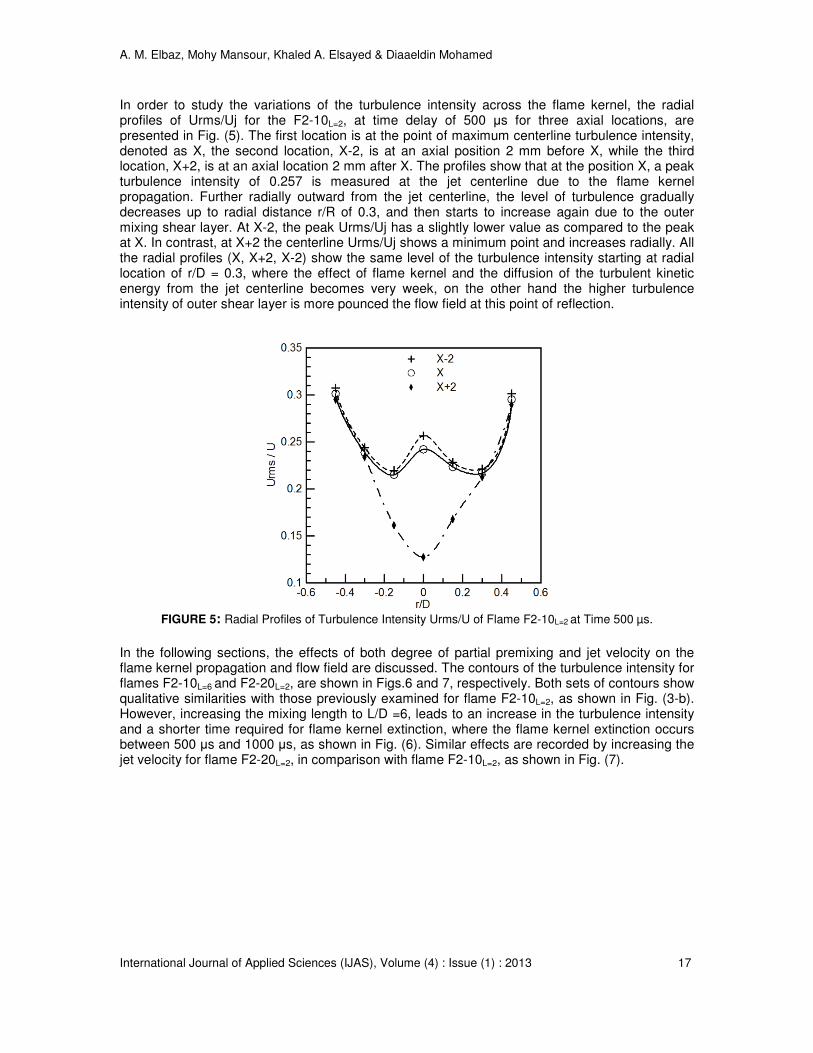
In order to study the variations of the turbulence intensity across the flame kernel, the radial profiles of Urms/Uj for the F2-10L=2, at time delay of 500 µs for three axial locations, are presented in Fig. (5). The first location is at the point of maximum centerline turbulence intensity, denoted as X, the second location, X-2, is at an axial position 2 mm before X, while the third location, X+2, is at an axial location 2 mm after X. The profiles show that at the position X, a peak turbulence intensity of 0.257 is measured at the jet centerline due to the flame kernel propagation. Further radially outward from the jet centerline, the level of turbulence gradually decreases up to radial distance r/R of 0.3, and then starts to increase again due to the outer mixing shear layer. At X-2, the peak Urms/Uj has a slightly lower value as compared to the peak at X. In contrast, at X+2 the centerline Urms/Uj shows a minimum point and increases radially. All the radial profiles (X, X+2, X-2) show the same level of the turbulence intensity starting at radial location of r/D = 0.3, where the effect of flame kernel and the diffusion of the turbulent kinetic energy from the jet centerline becomes very week, on the other hand the higher turbulence intensity of outer shear layer is more pounced the flow field at this point of reflection.
FIGURE 5: Radial Profiles of Turbulence Intensity Urms/U of Flame F2-10L=2 at Time 500 µs.
In the following sections, the effects of both degree of partial premixing and jet velocity on the flame kernel propagation and flow field are discussed. The contours of the turbulence intensity for flames F2-10L=6 and F2-20L=2, are shown in Figs.6 and 7, respectively. Both sets of contours show qualitative similarities with those previously examined for flame F2-10L=2, as shown in Fig. (3-b). However, increasing the mixing length to L/D =6, leads to an increase in the turbulence intensity and a shorter time required for flame kernel extinction, where the flame kernel extinction occurs between 500 µs and 1000 µs, as shown in Fig. (6). Similar effects are recorded by increasing the jet velocity for flame F2-20L=2, in comparison with flame F2-10L=2, as shown in Fig. (7).

A. M. Elbaz, Mohy Mansour, Khaled A. Elsayed & Diaaeldin Mohamed
International Journal of Applied Sciences (IJAS), Volume (4) : Issue (1) : 2013 18
FIGURE 6: The Turbulence Intensity Contours of F2-10L=6 with the Reference Isothermal Case.
FIGURE 7: The Turbulence Intensity Contours of F2-20L=2 with the Reference Isothermal Case.
As previously stated, increasing the mixing length L results in global increasing in the turbulence intensity for the isothermal cases. This is confirmed by the noticeably higher center line turbulence intensity in F2-10
isoL=6, at delay time of 300 µs, as shown in Fig. (8) than those of
L/D=4, and 2 for the isothermal cases. The longer shear layer accompanied by the longer outer pipe of F2-10
isoL=6 leads to higher turbulence intensity. This higher turbulence intensity for L/D=6
enhances the mixing between the fuel and air, thus resulting in a flame that is closer to the conditions of a fully premixed flame.
Consequently, two reasons can be considered as the causes of the low stability limit of the case of L/D =6, see Fig. (2); the first is the higher turbulence intensity, while the second is the more complete mixing between the fuel and air which breaks up the triple point structure of partially premixed flame, which improve the flame stability, see [24]. At the same time, increasing the degree of partial premixing results in higher centerline turbulence intensity, see Fig. (8) with the flame kernel. This is attributed to the higher turbulence intensity accompanying the isothermal case of L/D =6, as shown in Fig. (8). However, in all cases of L/D a nearly constant centerline turbulence level up to an axial distance of Y/D = 0.75 is observed. Further downstream, there is a

A. M. Elbaz, Mohy Mansour, Khaled A. Elsayed & Diaaeldin Mohamed
International Journal of Applied Sciences (IJAS), Volume (4) : Issue (1) : 2013 19
steep increase in turbulence intensity reaching a maximum point at the same axial distance of Y/D = 0.95; this is attributed to the dominating effect of the plasma associated with the laser ignition. Beyond the point of maximum turbulence at L/D = 6, the centerline turbulence level indicates a very slow decline up to axial distances of Y/D=1.5, and then is followed by very steep decline to a low turbulence level. Decreasing the mixing length leads to a shorter axial distance of the very low decline regions reaching to a point at L/D =2. This indicates that the shorter the mixing length, the sooner flame kernel extinction occurs (i.e., at shorter axial distances). A higher mixing rate leads to more uniform mixture and, hence, a higher speed of flame kernel propagation.
FIGURE 8: Centerline Axial Turbulence Intensity at Uj =10 m/s, L/D=2, L/D=4 and L/D=6.
Figure (9-a) illustrates the flame kernel propagation at different premixing lengths, while Fig. (9-b) shows the corresponding flame propagation rates. At jet velocity of 10 m/s, the flame propagation is the same for the three mixing lengths up to 150 µs, which indicates the effect of laser plasma is still pronounced. After a delay time of 150 µs increasing the mixing length L, leads to a higher flame propagation rate. This is may be attributed to higher mixture uniformity and higher turbulence intensity at a longer mixing length L. This higher L leads to faster extinction of the flame kernel, since higher mixing rates overcome the energy associated with the flame kernel leading to the early kernel quenching. Increasing the jet velocity results in a faster flame kernel propagation (see Uj=20 m/s). The higher the jet velocity, the larger the axial distance the flame kernel convected, as well as the higher the turbulence intensity, the higher the flame kernel penetration. As indicated in Fig. (9-b), for all the jet velocities, the flame kernel propagation rates are high up to delay time of 300 µs, which is followed by attenuated propagation rates. These attenuated propagation rates are due to the dissipated energy from the flame kernel to the surrounding mixture. Increasing the jet velocity leads to an increase of the flame kernel propagation rates and a shorter time for flame kernel extinction. These are attributed to the higher turbulence levels associated with higher jet velocities and the higher straining of the flame kernel associated with the higher jet velocity.

A. M. Elbaz, Mohy Mansour, Khaled A. Elsayed & Diaaeldin Mohamed
International Journal of Applied Sciences (IJAS), Volume (4) : Issue (1) : 2013 20
FIGURE 9: a) Flame Kernel Propagation, b) Rate of Flame Kernel Propagation.
5. CONCLUSIONS An experimental investigation is conducted on the interaction between the flow field and flame kernel propagation of partial premixed natural gas turbulent flames. The investigation is oriented to study the effect of the degree of partial premixing and jet velocity on the flow field-flame kernel interaction, while the jet equivalence ratio is kept constant. The mean flow field and turbulence intensity are measured using two-dimensional Planar Imaging Velocimetry (PIV). The flow field is captured for the isothermal field without ignition, and thus to be a reference flow field to those flow fields with ignition. The flow field with ignition is recorded after the start of ignition at different delay times. The mean flow field doesn't change for the ignited cases as compared to the isothermal flow. The flame kernel propagation is associated with an increase in turbulence intensity, and show a sudden increase in the centerline turbulence level. The higher degree of partial premixing leads to higher turbulence intensities accompanying the flame kernel propagation and faster flame kernel propagation. Increasing the jet velocity increases the global turbulence intensity and leads to faster flame kernel propagation. The rate of flame kernel propagation is very fast at the early stage of the kernel propagation up to the first 300 µs and then it slows down. Moreover, increasing the jet velocity and/or increasing the degree of partial premixing, leads to break out the partial premixing structure and hence a reduction inflame stability and a more rapid flame kernel extinction, attributed to the higher strain rates.
(A)
(B)

A. M. Elbaz, Mohy Mansour, Khaled A. Elsayed & Diaaeldin Mohamed
International Journal of Applied Sciences (IJAS), Volume (4) : Issue (1) : 2013 21
6. ACKNOWLEDGEMENTS This work is financially supported by the joint project between Cairo University, Egypt, and North
Carolina State University, USA. The project title is "Computational and Experimental Studies of
Turbulent Premixed Flame Kernels". The project ID is 422.
7. REFERENCES
[1] R.R. Maly, in: J.C. Hilliard, G.S. Springer (Eds.). Flow and Combustion in Reciprocating Engines. Plenum Press, New York; 1983.
[2] C.F. Kaminski, J. Hult, M. Alden, S. Lindenmaier, A. Dreizler, U. Mass, M. Baum. Complex
turbulence/chemistry interactions revealed by time resolved fluorescence and direct
numerical simulations. Proceedings of the Combustion Institute 2000; 28:399–405.
[3] A. Dreizler, S. Lindenmaier, U. Maas, J. Hult, M. Alden, C.F. Kaminski. Characterization of a
spark ignition system by planar laser induced fluorescence of high repetition rates and
comparison with chemical kinetic calculations. Applied Physics 2000; B70:287–294.
[4] S. Gashi, J. Hult, K.W. Jenkins, N. Chakraborty, R.S. Cant, C.F.Kaminski. Curvature and
wrinkling of premixed flame kernels – comparisons of OH PLIF and DNS data. Proceedings
of Combustion Institute 2005; 30:809–817.
[5] C.C. Huang, S.S. Shy, C.C. Liu, A. Yan. A transition on minimum ignition energy for lean
turbulent methane combustion in flamelet and distributed regimes. Proceedings of the
Combustion Institute 2007; 31:1401–1409.
[6] K.W. Jenkins, R.S. Cant. Curvature effects on flame kernels in a turbulent environment.
Proceedings of the Combustion Institute 2002; 29:2023–2029.
[7] D. Thevenin, O. Gicquel, J. de Charentenay, R. Hilbert, D. Veynante. Two versus three
dimensional direct simulations of turbulent methane flame kernels using realistic chemistry.
Proceedings of the Combustion Institute 2003; 29:2031–2039.
[8] N. Chakraborty, M. Klein, R.S. Cant. Stretch effects on displacement speed in turbulent
premixed flame kernels in the thin reaction zones regime. Proceedings of the Combustion
Institute 2007; 31: 1385–1392.
[9] K.W. Jenkins, M. Klein, N. Chakraborty, R.S. Cant. Effects of strain rate and curvature on the
propagation of a spherical flame kernel in the thin reaction zones regime. Combustion and
Flame 2006; 145:415–434.
[10] V.R. Katta, K.Y. Iisu, and W.M. Roquemore. Local Extinction in an unsteady methane-air jet
diffusion flame. Proceedings of the Combustion Institute 1998; 27:1121-1129.
[11] P.H. Renard, J.C. Rolon, D. Thevenin, , and S. Candel. Investigations of heat release,
extinction, and time evolution of the flame surface, for a non-premixed flame interacting with
a vortex. Combustion and Flame 1999; 117:189–205.
A. M. Elbaz, Mohy Mansour, Khaled A. Elsayed & Diaaeldin Mohamed
International Journal of Applied Sciences (IJAS), Volume (4) : Issue (1) : 2013 22
[12] C. Arcoumanis, D.R. Hall, and J. H. Whitelaw. An approach to charge stratification in lean-
burn spark-ignition engines. SAE technical paper 941878 (1994).
[13] C. Arcoumanis, D.R. Hall, and J.H. Whitelaw. Optimizing local charge stratification in a lean-
burn spark ignition engine. Proc. Instn. Mech. Engrs, Part D: J. Auto. Eng. 1997; 211:145–
154.
[14] C. Arcoumanis, M.R. Gold, J.H. Whitelaw, and H.M. Xu. Local mixture injection to extend the
lean limit of spark-ignition engines. Exper. Fluids 1999; 26:126–135.
[15] D.A. Eichenberger, W.L. Roberts. Effect of unsteady stretch on spark-ignited flame kernel
survival. Combust. Flame 1999; 118:469–478.
[16] Y. Xiong, W.L. Roberts, M.C. Drake, T.D. Fansler. Investigation of pre-mixed flame-
kernel/vortex interactions via high-speed imaging. Combust. Flame 2001; 126:1827–1844.
[17] Y. Xiong, W.L. Roberts. Observations on the interaction between a premixed flame kernel
and a vortex of different equivalence ratio. Proc. Combust. Inst. 2002; 29:1687–1693.
[18] D. Thevenin, P.H. Renard, J.C. Rolon, and S. Candel. Extinction processes during a non-
premixed flame / vortex interaction. Proc. Combust. Inst. 1998; 27:719–726.
[19] P.H. Renard, J.C. Rolon, D. Thevenin, and S. Candel. Wrinkling, pocket formation and
double premixed flame interaction processes. Proc. Combust. Inst. 1998; 27:659–666.
[20] G. Patnaik, and K. Kailasanath. A computational study of local quenching in flame-vortex
interactions with radiative losses. Proc. Combust. Inst. 1998; 27:711–717.
[21] M.S. Mansour, , N. Peters, L.U. Schrader. Experimental study of turbulent flame kernel
propagation. Experimental Thermal and Fluid Science. 2008; 32:1396–1404.
[22] A. M. Elbaz, M. Mansour, and D. Mohamed. Experimental Investigation of Flame Kernel Propagation in Partial Premixed Flame. International Journal of Applied Sciences (IJAS) 2012; Vol. 3 (2): 21-34.
[23] B.D. Videto, D.A. Santavicca. A turbulent flow system for studying turbulent combustion
processes. Combustion Science and Technology 1991; 76:159–164.
[24] F. EL-Mahallawy, A. Abdelhaffz, M. Mansour. Mixing and nozzle geometry effects on flame
structure and stability. Comb. Sci. Technol. 2007; 179: 249-263.