Embed Size (px)
Citation preview
ARC 2523 Project 1 Fettuccine Truss Bridge
1
ARC 2523 BUILDING STRUCTURE
PROJECT FETTUCCINE BRIDGE REPORT
Chan Pin Qi 0314676
Lim Yee Qun 0319121
Te Li Theng 0314198
Liew Qiao Li 0315671
Woo Wen Jian 0315123
9th October 2015
ARC 2523 Project 1 Fettuccine Truss Bridge
2
TABLE OF CONTENTS
CHAPTER 1: INTRODUCTION 1.1 Introduction to the Project 1.2 Aim and Objective 1.3 Scope 1.4 Limitations 1.5 Equipment and Materials Used 1.6 Testing of Materials 1.7 Methodology 1.8 Schedule of Work
3 4 5 5 6-9 10 11-12 13
CHAPTER 2: PRECEDENT STUDY
2.1 Wadell “A” Truss Bridge, Parkville, Missouri 2.2 Design Strategies and Load Distribution 2.3 Trusses and Connection
14 15 16-17
CHAPTER 3: EXPERIMENTATION AND PROGRESS 3.1 Bridge Truss Design 1 vs Bridge Truss Design 2 3.2 Bridge Truss Design 3 3.3 Bridge Truss Design 4 3.4 Bridge Truss Design 5
18-21 22-23 24-25 26-27
CHAPTER 4: FINAL BRIDGE 4.1 Amendments 4.2 Top & Bottom Chord 4.3 Core Horizontal Element 4.4 Vertical & Diagonal Truss 4.5 Joints 4.6 Members & Connection of Fettuccini Bridge 4.7 Joint Analysis 4.8 Final Model Making 4.9 Final Bridge Test and Load Distribution 4.10 Calculation of Distribution of Forces for Final Bridge
28 29 30 31 32 33 34-39 40-44 45 46-50
CHAPTER 5: REFERENCES 51
CHAPTER 6: INDIVIDUAL CASE STUDIES 6.1 Case Study 1: Chan Pin Qi 6.2 Case Study 2: Lim Yee Qun 6.3 Case Study 3: Te Li Teng 6.4 Case Study 4: Liew Qiao Li 6.5 Case Study 5: Woo Wen Jian
52-55 56-59 60-63 64-67 68-71
ARC 2523 Project 1 Fettuccine Truss Bridge
3
Chapter 1: Introduction
1.1 Introduction to the Project
This project is commissioned by AR2523: Building structures. In a group of five, students are
assigned to build a bridge using fettuccine as the materials for the bridge truss members.
The weight of the bridge must not be more than 80g, but is required to carry a much larger
weight for an extended period of time. The clear span of the bridge must be at least
350mm.
With many unknown variables, including its compression and tension capabilities, students
are asked to experiment with different kind of methods of joint and designs to determine
the best design for a bridge. Students will learn to explore truss members using different
arrangements to achieve the best performance and how to build the prefect truss. Students
are to find out the strength of each design by testing out and find out its tension and
compression forces.
Students will then apply the knowledge of calculating the moment force, reaction force,
internal force and force distribution of a truss. By identifying all these forces, students will
be able to enhance their design by determining which members need amendment in order
to make it stronger.
This report contains information regarding the students' analysis and documentation of the
experimentation with several fettuccine truss bridge designs. Individual case studies are also
in these reports, along with insight and suggestions for improvement.
ARC 2523 Project 1 Fettuccine Truss Bridge
4
1.2 Aim and Objective
The aim of this project is to develop students' understanding of force distribution in a truss.
It also aims to teach that different design and construction methods can alter the efficiency
in withstanding loads.
The objective of this project is to discover the most efficient bridge design with fettuccine as
material in regards to its tension and compression capabilities. Students are also to learn
how different forces (tension and compression) to affect a bridge efficiency, especially
considering fettuccine as a relatively weak materials.
Also, the project aims to teach students to build a perfect truss, a truss design with high
aesthetic value, and at the same time with a minimal construction material that could
withstand a high amount of loads.
ARC 2523 Project 1 Fettuccine Truss Bridge
5
1.3 Scope
The scope of this project was to use only fettuccine as the construction material. The bridge
constructed is required to have a clear span of 350mm and a weight lesser than 80g. Prior to
deciding the final truss bridge design, process such as preparing precedent studies, material
durability test, model making and load testing process were conducted. This is to explore
which ways that could enhance the bridge design to hold more loads.
1.4 Limitations
Our main limitation was that the weight of the bridge must not exceed the range of
80grams. This caused us to carefully study how do the forces distribute in the bridges that
we designed and how could we enhanced the strength of the bridge design and at the same
time, to minimize the construction materials. Consequently, a lot of designs were produced
in order to get the perfect design.
ARC 2523 Project 1 Fettuccine Truss Bridge
6
1.5 Equipment and Materials Used
San Remo Fettuccine: San Remo brand’s fettuccine is the best in term of cost to
compression strength compared to the other brands during the
material durability test.
Cutting knife: Cutting knife was used to cut the fettuccine to pieces during the
making of the bridge truss to achieve the precision that is close to
what we wanted to design.
3-second glue: Used when gluing the bridge joint together. It has great adhesion
strength that allows fettuccine to join together in about 3-5 seconds.
ARC 2523 Project 1 Fettuccine Truss Bridge
7
Cutting mat: Used to protect the table surface when cutting the fettuccine as well
as the edges of the fettuccine.
Steel Ruler: Used to measure the length and marking on each fettuccine before
cutting it.
Sandpaper: Used to smoothen the edges of the fettuccine after cutting and
before gluing.
ARC 2523 Project 1 Fettuccine Truss Bridge
8
500 ml water bottle: Used as load during the load testing of the bridge. It is much more
faster to test out the designs this way.
Thin ropes: Used to hang both centre components and S hook together. The
force distributed is much more even compared to using the s hook to
the centre component
Phones: Used to record and document the results of each of the designs
during the test.
ARC 2523 Project 1 Fettuccine Truss Bridge
9
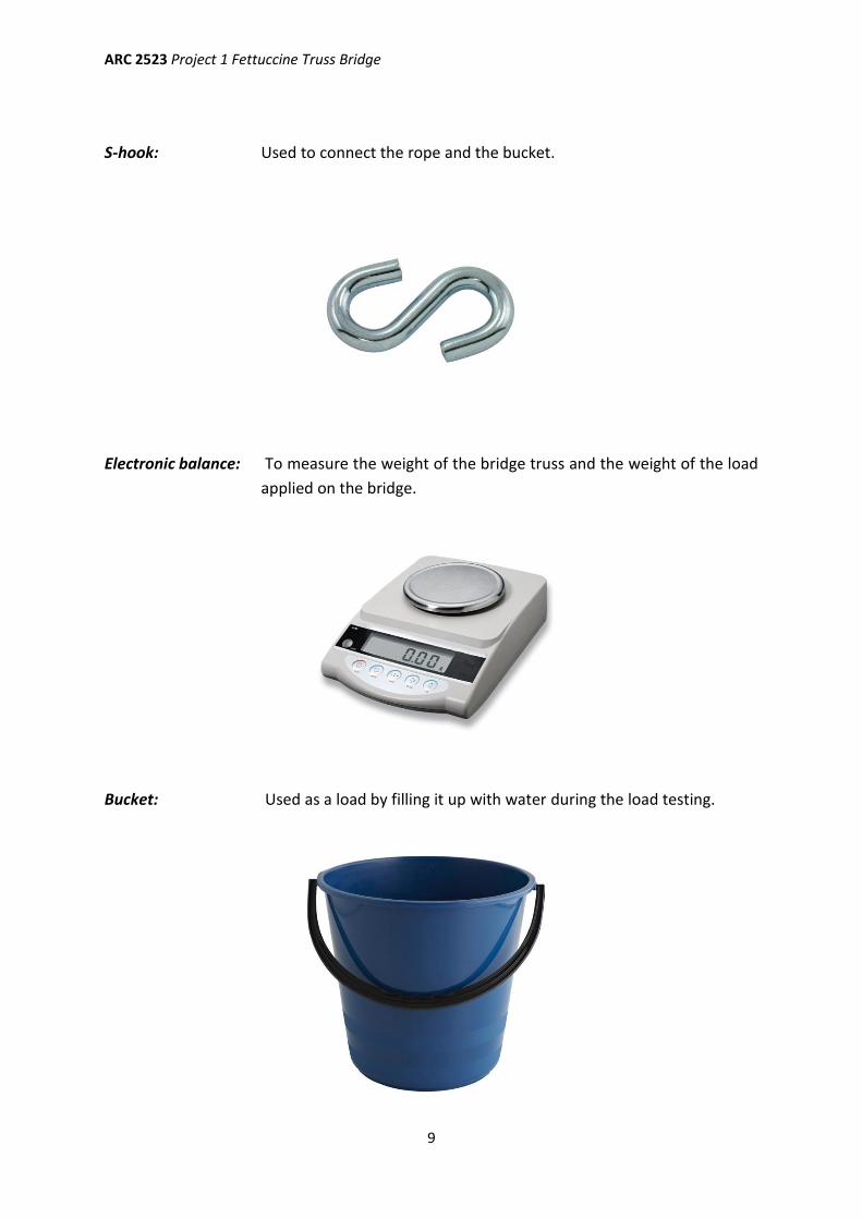
S-hook: Used to connect the rope and the bucket.
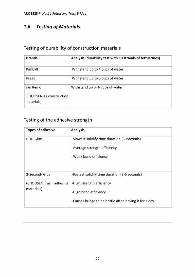
Electronic balance: To measure the weight of the bridge truss and the weight of the load
applied on the bridge.
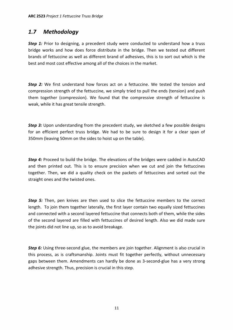
Bucket: Used as a load by filling it up with water during the load testing.
ARC 2523 Project 1 Fettuccine Truss Bridge
10
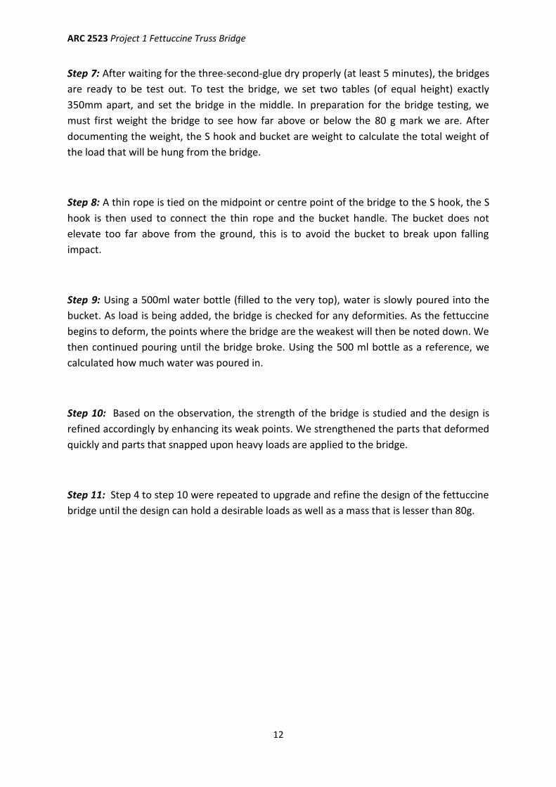
1.6 Testing of Materials
Testing of durability of construction materials
Brands Analysis (durability test with 10 strands of fettuccines)
Kimball Withstand up to 4 cups of water
Prego Withstand up to 5 cups of water
San Remo
(CHOOSEN as construction
materials)
Withstand up to 6 cups of water
Testing of the adhesive strength
Types of adhesive Analysis
UHU Glue -Slowest solidify time duration (30seconds)
-Average strength efficiency
-Weak bond efficiency
3-Second- Glue
(CHOOSEN as adhesive
materials)
-Fastest solidify time duration (3-5 seconds)
-High strength efficiency
-High bond efficiency
-Causes bridge to be brittle after leaving it for a day
ARC 2523 Project 1 Fettuccine Truss Bridge
11
1.7 Methodology
Step 1: Prior to designing, a precedent study were conducted to understand how a truss
bridge works and how does force distribute in the bridge. Then we tested out different
brands of fettuccine as well as different brand of adhesives, this is to sort out which is the
best and most cost effective among all of the choices in the market.
Step 2: We first understand how forces act on a fettuccine. We tested the tension and
compression strength of the fettuccine, we simply tried to pull the ends (tension) and push
them together (compression). We found that the compressive strength of fettuccine is
weak, while it has great tensile strength.
Step 3: Upon understanding from the precedent study, we sketched a few possible designs
for an efficient perfect truss bridge. We had to be sure to design it for a clear span of
350mm (leaving 50mm on the sides to hoist up on the table).
Step 4: Proceed to build the bridge. The elevations of the bridges were cadded in AutoCAD
and then printed out. This is to ensure precision when we cut and join the fettuccines
together. Then, we did a quality check on the packets of fettuccines and sorted out the
straight ones and the twisted ones.
Step 5: Then, pen knives are then used to slice the fettuccine members to the correct
length. To join them together laterally, the first layer contain two equally sized fettuccines
and connected with a second layered fettuccine that connects both of them, while the sides
of the second layered are filled with fettuccines of desired length. Also we did made sure
the joints did not line up, so as to avoid breakage.
Step 6: Using three-second glue, the members are join together. Alignment is also crucial in
this process, as is craftsmanship. Joints must fit together perfectly, without unnecessary
gaps between them. Amendments can hardly be done as 3-second-glue has a very strong
adhesive strength. Thus, precision is crucial in this step.
ARC 2523 Project 1 Fettuccine Truss Bridge
12
Step 7: After waiting for the three-second-glue dry properly (at least 5 minutes), the bridges
are ready to be test out. To test the bridge, we set two tables (of equal height) exactly
350mm apart, and set the bridge in the middle. In preparation for the bridge testing, we
must first weight the bridge to see how far above or below the 80 g mark we are. After
documenting the weight, the S hook and bucket are weight to calculate the total weight of
the load that will be hung from the bridge.
Step 8: A thin rope is tied on the midpoint or centre point of the bridge to the S hook, the S
hook is then used to connect the thin rope and the bucket handle. The bucket does not
elevate too far above from the ground, this is to avoid the bucket to break upon falling
impact.
Step 9: Using a 500ml water bottle (filled to the very top), water is slowly poured into the
bucket. As load is being added, the bridge is checked for any deformities. As the fettuccine
begins to deform, the points where the bridge are the weakest will then be noted down. We
then continued pouring until the bridge broke. Using the 500 ml bottle as a reference, we
calculated how much water was poured in.
Step 10: Based on the observation, the strength of the bridge is studied and the design is
refined accordingly by enhancing its weak points. We strengthened the parts that deformed
quickly and parts that snapped upon heavy loads are applied to the bridge.
Step 11: Step 4 to step 10 were repeated to upgrade and refine the design of the fettuccine
bridge until the design can hold a desirable loads as well as a mass that is lesser than 80g.

ARC 2523 Project 1 Fettuccine Truss Bridge
13
1.8 Schedule of Work
9th Sept 2015 Experimentation on the most durable brand of fettuccine and the
adhesive with the most strength.
Research and preliminary sketches, discussion of possible design ideas
for Bridge#1
15th Sept 2015 Deciding on the design of the first bridge to be built
Research and preliminary sketches, discussion of possible design ideas
for Bridge#2
19th Sept 2015 Building of Bridge#1 and Bridge#2
23th Sept 2015 Discussion of the weakness of Bridge#1 and Bridge#2 on its designs.
Joints have the most weakness.
Discussed possible method to join members together.
Introduced I-beams to designs.
26th Sept 2015 Research and preliminary sketches, discussion of possible design ideas
for Bridge#3.
Building of Bridge#3.
Testing of Bridge#1, Bridge#2 and Bridge#3.
Research and preliminary sketches, discussion of possible design ideas
for Bridge#4.
27th – 28th Sept 2015 Building of Bridge#4.
Testing of Bridge#4.
Research and preliminary sketches, discussion of possible design ideas
for Bridge#5.
Building of Bridge#5.
Testing of Bridge#5.
Decided on Bridge#5 as the design for assessment.
Building of Bridge#6
Assessment of Bridge#6
ARC 2523 Project 1 Fettuccine Truss Bridge
14
Chapter 2: PRECEDENT STUDIES
2.1 Wadell “A” Truss Bridge, Parkville, Missouri.
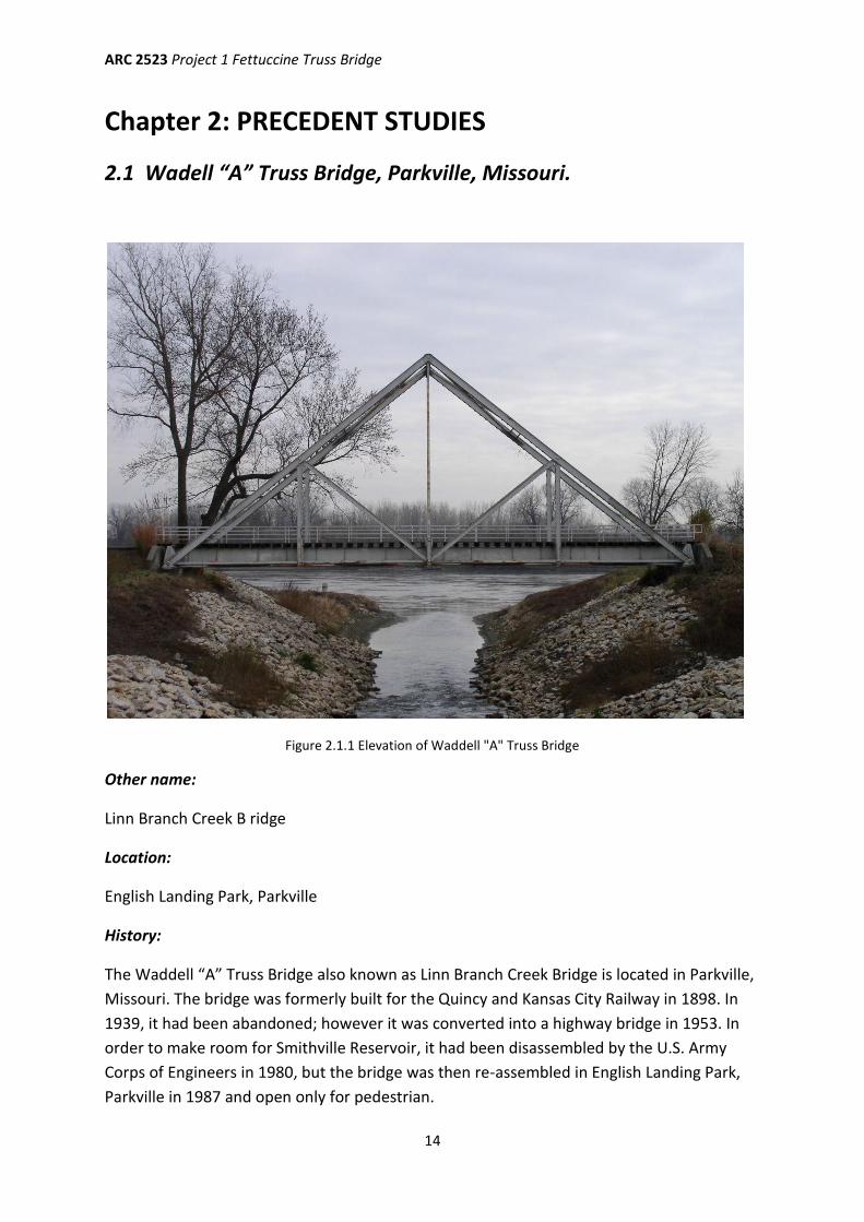
Figure 2.1.1 Elevation of Waddell "A" Truss Bridge
Other name:
Linn Branch Creek B ridge
Location:
English Landing Park, Parkville
History:
The Waddell “A” Truss Bridge also known as Linn Branch Creek Bridge is located in Parkville,
Missouri. The bridge was formerly built for the Quincy and Kansas City Railway in 1898. In
1939, it had been abandoned; however it was converted into a highway bridge in 1953. In
order to make room for Smithville Reservoir, it had been disassembled by the U.S. Army
Corps of Engineers in 1980, but the bridge was then re-assembled in English Landing Park,
Parkville in 1987 and open only for pedestrian.
ARC 2523 Project 1 Fettuccine Truss Bridge
15
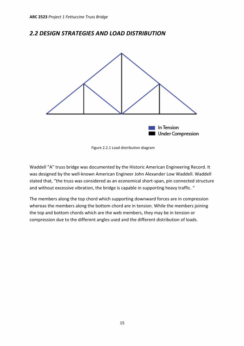
2.2 DESIGN STRATEGIES AND LOAD DISTRIBUTION
Waddell “A” truss bridge was documented by the Historic American Engineering Record. It
was designed by the well-known American Engineer John Alexander Low Waddell. Waddell
stated that, “the truss was considered as an economical short-span, pin connected structure
and without excessive vibration, the bridge is capable in supporting heavy traffic. “
The members along the top chord which supporting downward forces are in compression
whereas the members along the bottom chord are in tension. While the members joining
the top and bottom chords which are the web members, they may be in tension or
compression due to the different angles used and the different distribution of loads.
Figure 2.2.1 Load distribution diagram
ARC 2523 Project 1 Fettuccine Truss Bridge
16
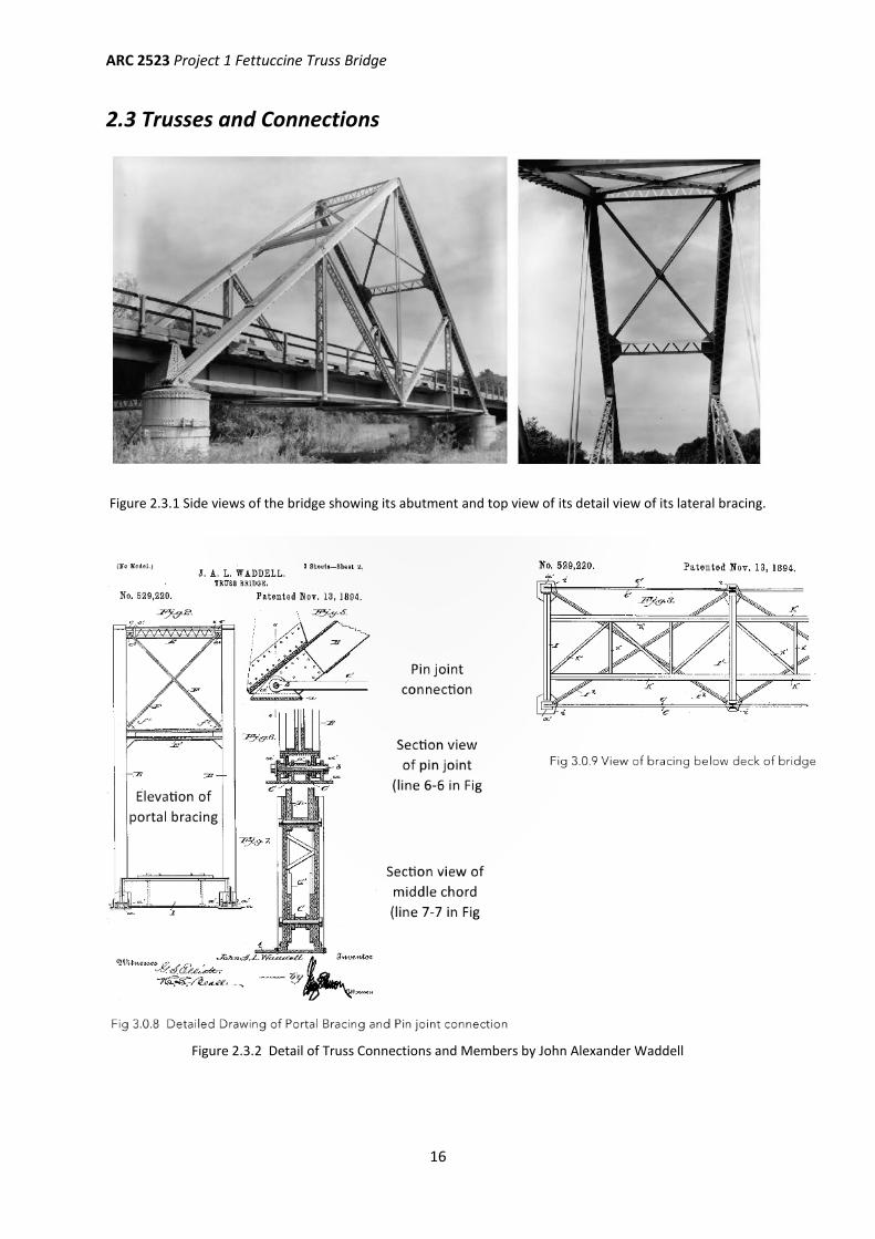
2.3 Trusses and Connections
Figure 2.3.1 Side views of the bridge showing its abutment and top view of its detail view of its lateral bracing.
Figure 2.3.2 Detail of Truss Connections and Members by John Alexander Waddell
ARC 2523 Project 1 Fettuccine Truss Bridge
17
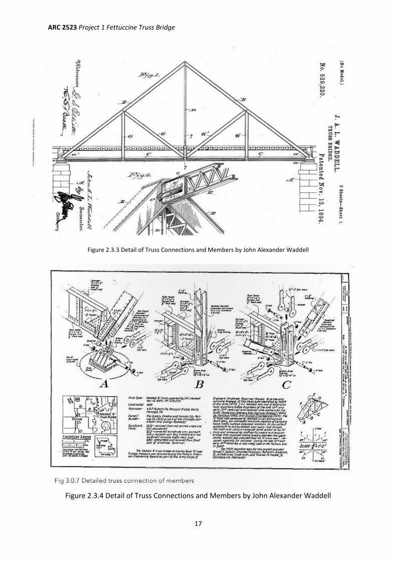
Figure 2.3.3 Detail of Truss Connections and Members by John Alexander Waddell
Figure 2.3.4 Detail of Truss Connections and Members by John Alexander Waddell
ARC 2523 Project 1 Fettuccine Truss Bridge
18
Chapter 3: EXPERIMENTATION AND PROGRESS
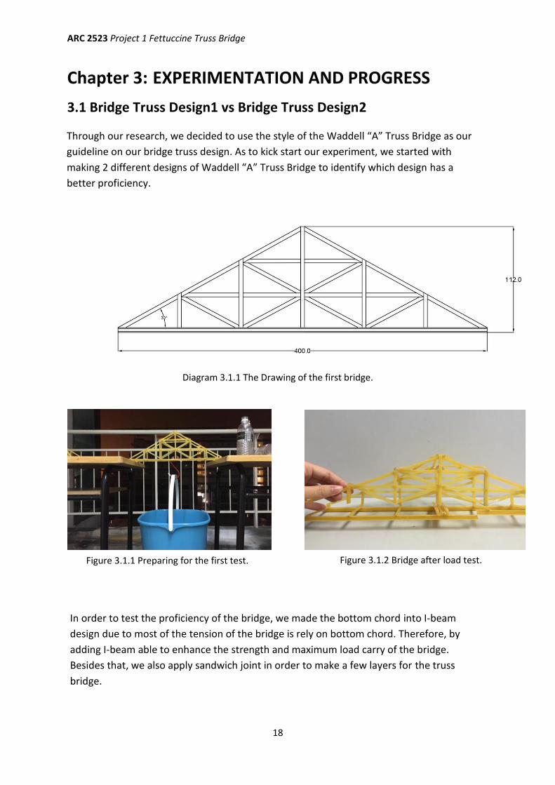
3.1 Bridge Truss Design1 vs Bridge Truss Design2
Diagram 3.1.1 The Drawing of the first bridge.
Figure 3.1.2 Bridge after load test. Figure 3.1.1 Preparing for the first test.
Through our research, we decided to use the style of the Waddell “A” Truss Bridge as our
guideline on our bridge truss design. As to kick start our experiment, we started with
making 2 different designs of Waddell “A” Truss Bridge to identify which design has a
better proficiency.
In order to test the proficiency of the bridge, we made the bottom chord into I-beam
design due to most of the tension of the bridge is rely on bottom chord. Therefore, by
adding I-beam able to enhance the strength and maximum load carry of the bridge.
Besides that, we also apply sandwich joint in order to make a few layers for the truss
bridge.

ARC 2523 Project 1 Fettuccine Truss Bridge
19
Diagram 3.1.2 Breakage point of Bridge1, which all located at the bottom chord.
3.2 Bridge Truss Design2 (Chosen to Further Improvise)
Bridge Weight 81g
Load Carried 1300g
Efficiency 20.86
Figure 3.1.3 The truss of Bridge1 detached
from bottom chord.
Figure 3.1.4 The bottom chord of Bridge1
breaks nearby the joint connection.
During the load testing experiment, although the truss did not break but it was detached from
the bottom chord at certain amount of load. Besides, I-beam was used as our bottom chord to
enhance the efficiency of the bridge but we do not realized that the connection of I-beam also
affect the bridge to break down. This is because the breakage of bridge occurred at the bottom
chord and also it breaks at the part where we join the fettuccines together.
From our observation of this experiment, we believed that the failure of the bridge occurred
mainly due to our poor workmanship.
ARC 2523 Project 1 Fettuccine Truss Bridge
20
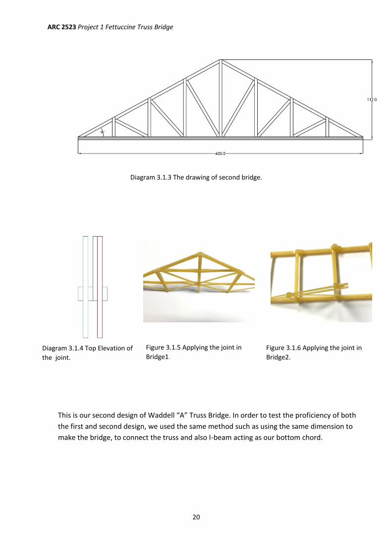
Diagram 3.1.3 The drawing of second bridge.
Diagram 3.1.4 Top Elevation of
the joint.
Figure 3.1.5 Applying the joint in
Bridge1.
Figure 3.1.6 Applying the joint in
Bridge2.
This is our second design of Waddell “A” Truss Bridge. In order to test the proficiency of both
the first and second design, we used the same method such as using the same dimension to
make the bridge, to connect the truss and also I-beam acting as our bottom chord.
ARC 2523 Project 1 Fettuccine Truss Bridge
21
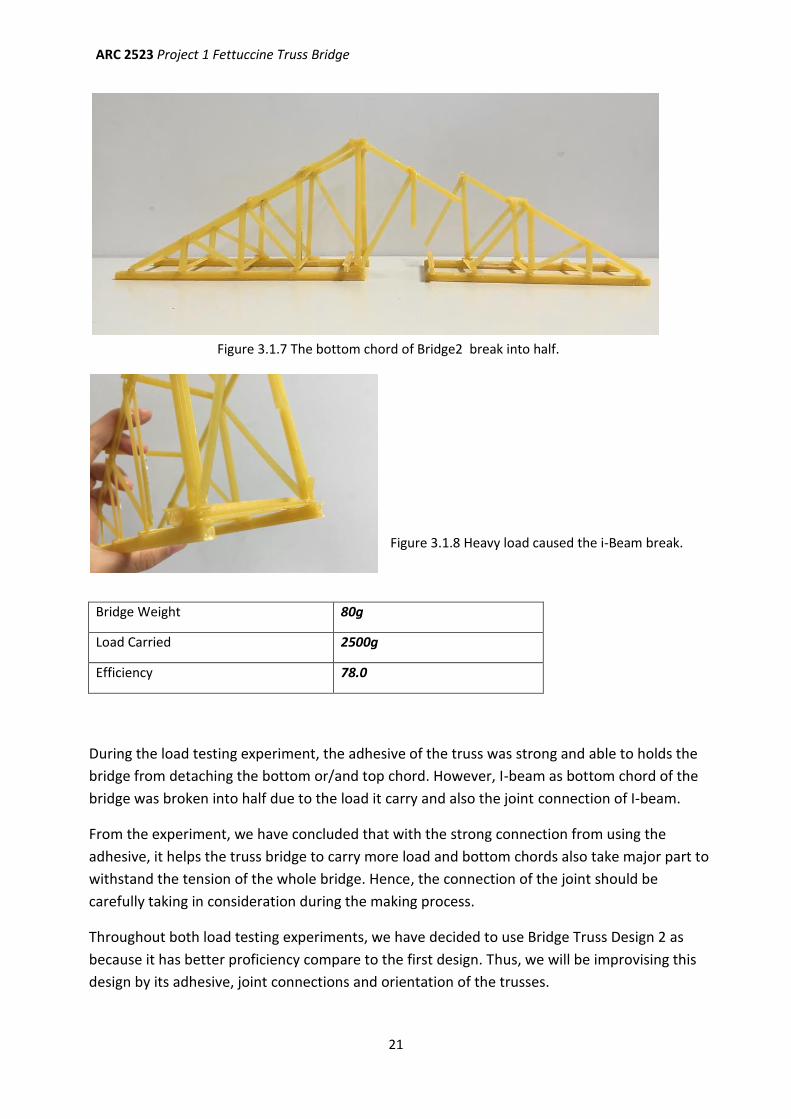
3.3 Bridge Truss Design3
Bridge Weight 80g
Load Carried 2500g
Efficiency 78.0
Figure 3.1.7 The bottom chord of Bridge2 break into half.
Figure 3.1.8 Heavy load caused the i-Beam break.
During the load testing experiment, the adhesive of the truss was strong and able to holds the
bridge from detaching the bottom or/and top chord. However, I-beam as bottom chord of the
bridge was broken into half due to the load it carry and also the joint connection of I-beam.
From the experiment, we have concluded that with the strong connection from using the
adhesive, it helps the truss bridge to carry more load and bottom chords also take major part to
withstand the tension of the whole bridge. Hence, the connection of the joint should be
carefully taking in consideration during the making process.
Throughout both load testing experiments, we have decided to use Bridge Truss Design 2 as
because it has better proficiency compare to the first design. Thus, we will be improvising this
design by its adhesive, joint connections and orientation of the trusses.
ARC 2523 Project 1 Fettuccine Truss Bridge
22
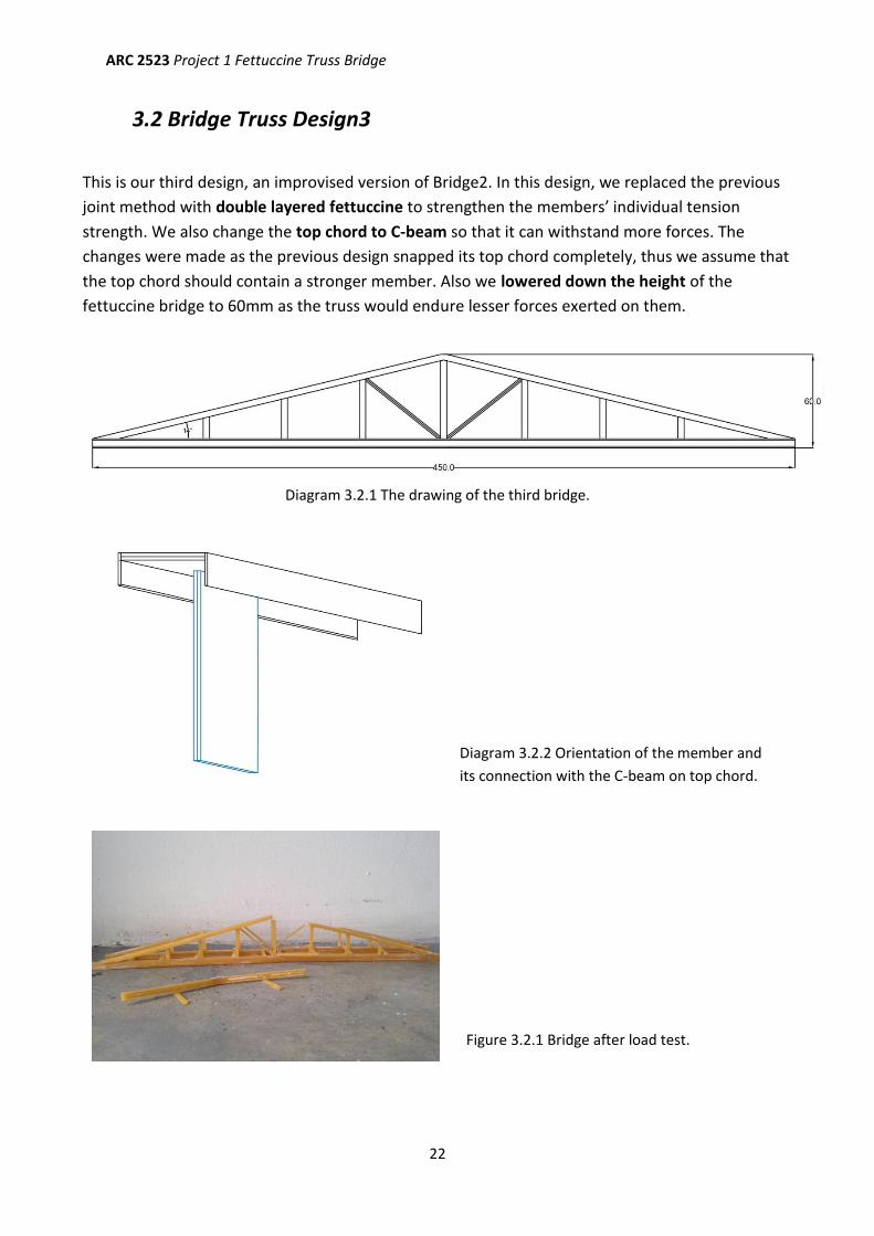
3.2 Bridge Truss Design3
Diagram 3.2.1 The drawing of the third bridge.
Diagram 3.2.2 Orientation of the member and
its connection with the C-beam on top chord.
Figure 3.2.1 Bridge after load test.
This is our third design, an improvised version of Bridge2. In this design, we replaced the previous
joint method with double layered fettuccine to strengthen the members’ individual tension
strength. We also change the top chord to C-beam so that it can withstand more forces. The
changes were made as the previous design snapped its top chord completely, thus we assume that
the top chord should contain a stronger member. Also we lowered down the height of the
fettuccine bridge to 60mm as the truss would endure lesser forces exerted on them.
ARC 2523 Project 1 Fettuccine Truss Bridge
23
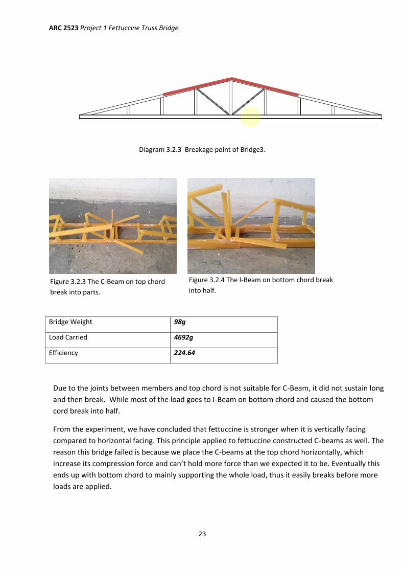
Diagram 3.2.3 Breakage point of Bridge3.
Bridge Weight 98g
Load Carried 4692g
Efficiency 224.64
Figure 3.2.4 The I-Beam on bottom chord break
into half. Figure 3.2.3 The C-Beam on top chord
break into parts.
Due to the joints between members and top chord is not suitable for C-Beam, it did not sustain long
and then break. While most of the load goes to I-Beam on bottom chord and caused the bottom
cord break into half.
From the experiment, we have concluded that fettuccine is stronger when it is vertically facing
compared to horizontal facing. This principle applied to fettuccine constructed C-beams as well. The
reason this bridge failed is because we place the C-beams at the top chord horizontally, which
increase its compression force and can’t hold more force than we expected it to be. Eventually this
ends up with bottom chord to mainly supporting the whole load, thus it easily breaks before more
loads are applied.
ARC 2523 Project 1 Fettuccine Truss Bridge
24
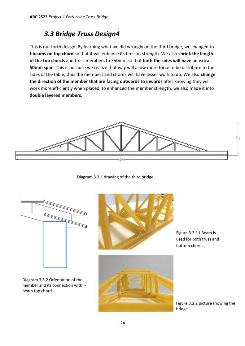
3.3 Bridge Truss Design4
This is our forth design. By learning what we did wrongly on the third bridge, we changed to
I-beams on top chord so that it will enhance its tension strength. We also shrink the length
of the top chords and truss members to 350mm so that both the sides will have an extra
50mm span. This is because we realize that way will allow more force to be distribute to the
sides of the table, thus the members and chords will have lesser work to do. We also change
the direction of the member that are facing outwards to inwards after knowing they will
work more efficiently when placed, to enhanced the member strength, we also made it into
double layered members.
Diagram 3.3.1 drawing of the third bridge
Figure 3.3.1 I-Beam is
used for both truss and
bottom chord.
Figure 3.3.2 Two i-Beam are used as the core
horizontal member to hang the one-point-load.
Diagram 3.3.2 Orientation of the member and its connection with I-beam top chord
Figure 3.3.2 picture showing the bridge
ARC 2523 Project 1 Fettuccine Truss Bridge
25
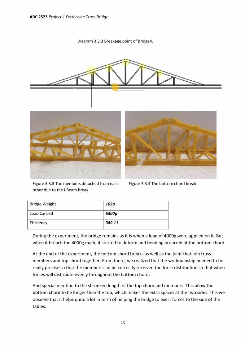
Diagram 3.3.3 Breakage point of Bridge4.
Bridge Weight 102g
Load Carried 6300g
Efficiency 389.11
Figure 3.3.3 The members detached from each
other due to the i-Beam break.
Figure 3.3.4 The bottom chord break.
During the experiment, the bridge remains as it is when a load of 4000g were applied on it. But
when it breach the 4000g mark, it started to deform and bending occurred at the bottom chord.
At the end of the experiment, the bottom chord breaks as well as the joint that join truss
members and top chord together. From there, we realized that the workmanship needed to be
really precise so that the members can be correctly received the force distribution so that when
forces will distribute evenly throughout the bottom chord.
And special mention to the shrunken length of the top chord and members. This allow the
bottom chord to be longer than the top, which makes the extra spaces at the two sides. This we
observe that it helps quite a lot in term of helping the bridge to exert forces to the side of the
tables.
ARC 2523 Project 1 Fettuccine Truss Bridge
26
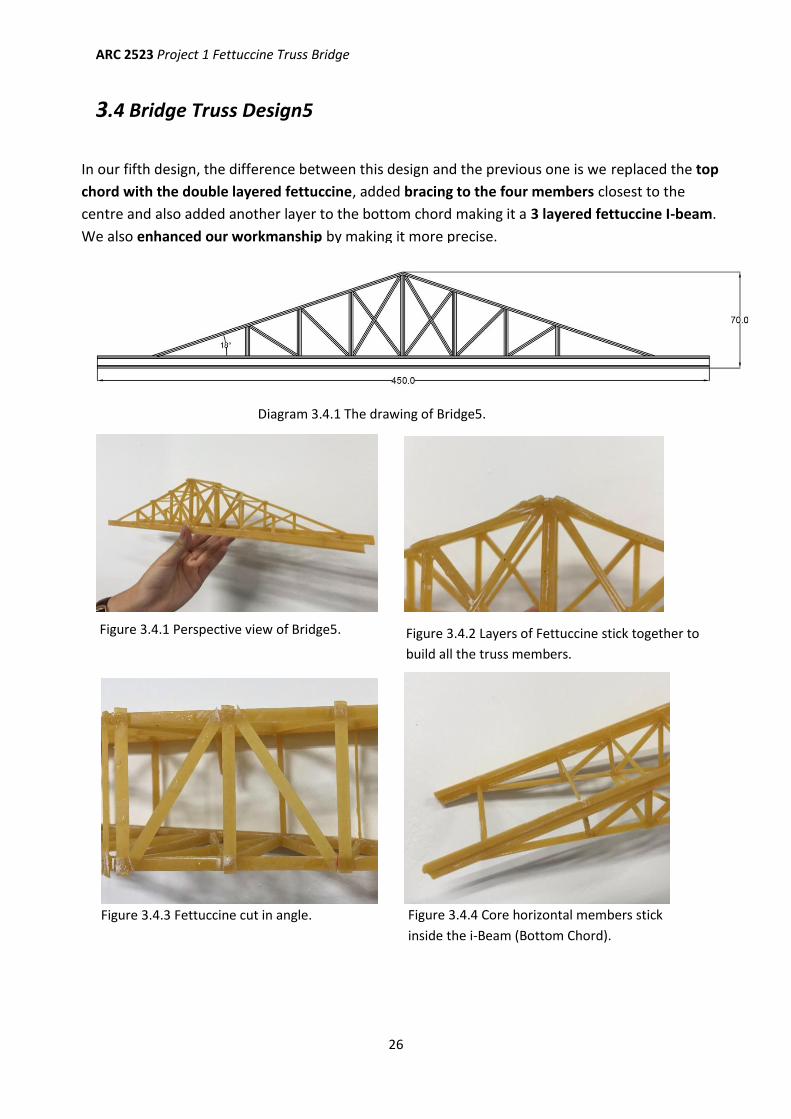
3.4 Bridge Truss Design5
Diagram 3.4.1 The drawing of Bridge5.
Figure 3.4.1 Perspective view of Bridge5. Figure 3.4.2 Layers of Fettuccine stick together to
build all the truss members.
Figure 3.4.3 Fettuccine cut in angle. Figure 3.4.4 Core horizontal members stick
inside the i-Beam (Bottom Chord).
In our fifth design, the difference between this design and the previous one is we replaced the top
chord with the double layered fettuccine, added bracing to the four members closest to the
centre and also added another layer to the bottom chord making it a 3 layered fettuccine I-beam.
We also enhanced our workmanship by making it more precise.
ARC 2523 Project 1 Fettuccine Truss Bridge
27
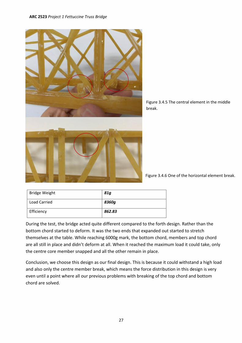
Bridge Weight 81g
Load Carried 8360g
Efficiency 862.83
Figure 3.4.5 The central element in the middle
break.
Figure 3.4.6 One of the horizontal element break.
During the test, the bridge acted quite different compared to the forth design. Rather than the
bottom chord started to deform. It was the two ends that expanded out started to stretch
themselves at the table. While reaching 6000g mark, the bottom chord, members and top chord
are all still in place and didn’t deform at all. When it reached the maximum load it could take, only
the centre core member snapped and all the other remain in place.
Conclusion, we choose this design as our final design. This is because it could withstand a high load
and also only the centre member break, which means the force distribution in this design is very
even until a point where all our previous problems with breaking of the top chord and bottom
chord are solved.
ARC 2523 Project 1 Fettuccine Truss Bridge
28
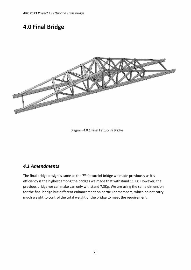
4.0 Final Bridge
4.1 Amendments
The final bridge design is same as the 7th fettuccini bridge we made previously as it’s
efficiency is the highest among the bridges we made that withstand 11 Kg. However, the
previous bridge we can make can only withstand 7.3Kg. We are using the same dimension
for the final bridge but different enhancement on particular members, which do not carry
much weight to control the total weight of the bridge to meet the requirement.
Diagram 4.0.1 Final Fettuccini Bridge
ARC 2523 Project 1 Fettuccine Truss Bridge
29
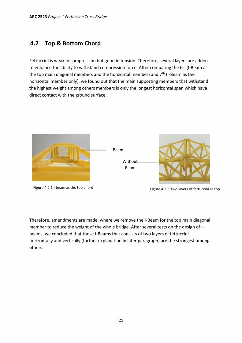
4.2 Top & Bottom Chord
Fettuccini is weak in compression but good in tension. Therefore, several layers are added
to enhance the ability to withstand compression force. After comparing the 6th (I-Beam as
the top main diagonal members and the horizontal member) and 7th (I-Beam as the
horizontal member only), we found out that the main supporting members that withstand
the highest weight among others members is only the longest horizontal span which have
direct contact with the ground surface.
Therefore, amendments are made, where we remove the I-Beam for the top main diagonal
member to reduce the weight of the whole bridge. After several tests on the design of I-
beams, we concluded that those I-Beams that consists of two layers of fettuccini
horizontally and vertically (further explanation in later paragraph) are the strongest among
others.
I-Beam
Without
I-Beam
Figure 4.2.1 I-beam as the top chord
member Figure 4.2.3 Two layers of fettuccini as top
chord member
ARC 2523 Project 1 Fettuccine Truss Bridge
30
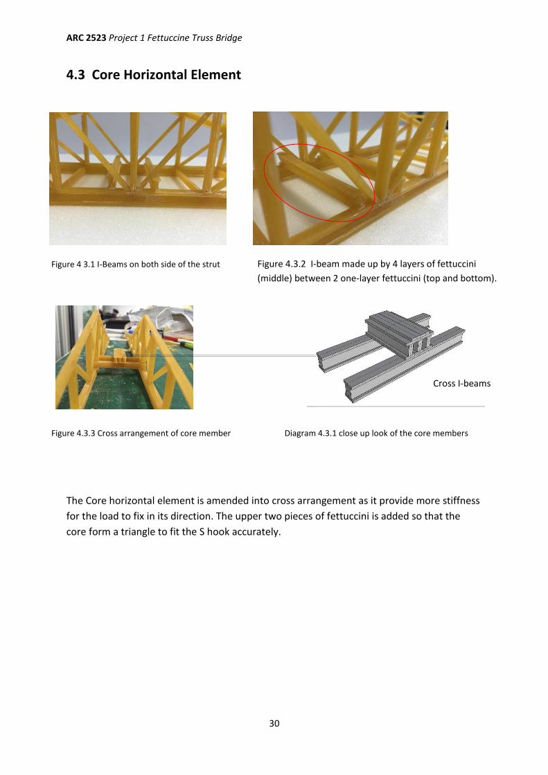
4.3 Core Horizontal Element
The Core horizontal element is amended into cross arrangement as it provide more stiffness
for the load to fix in its direction. The upper two pieces of fettuccini is added so that the
core form a triangle to fit the S hook accurately.
Cross I-beams
Diagram 4.3.1 close up look of the core members Figure 4.3.3 Cross arrangement of core member
Figure 4 3.1 I-Beams on both side of the strut Figure 4.3.2 I-beam made up by 4 layers of fettuccini
(middle) between 2 one-layer fettuccini (top and bottom).
ARC 2523 Project 1 Fettuccine Truss Bridge
31
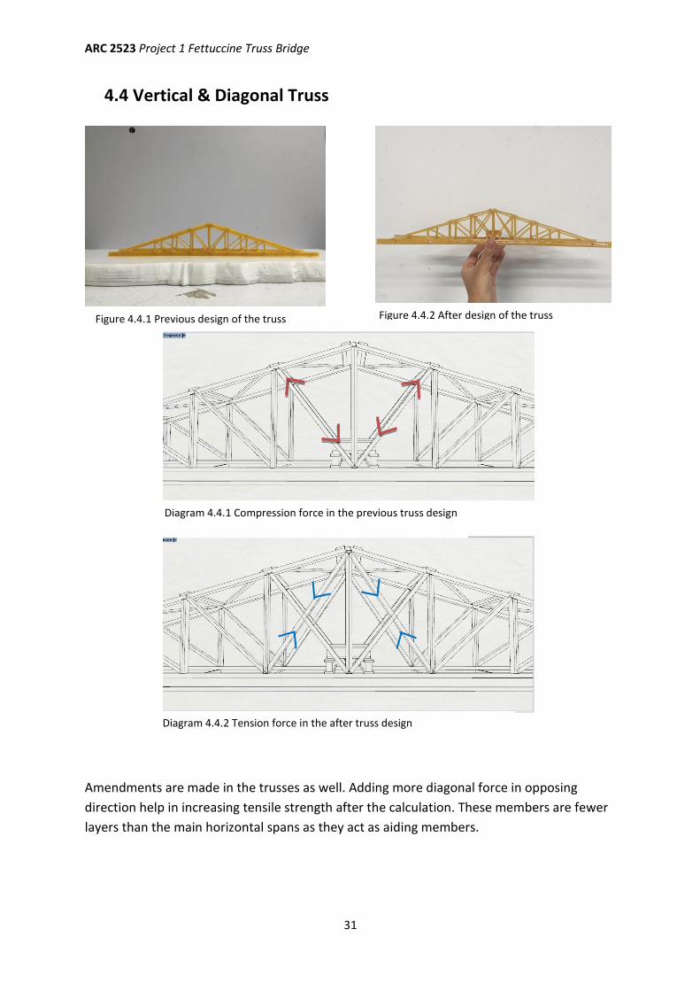
4.4 Vertical & Diagonal Truss
Amendments are made in the trusses as well. Adding more diagonal force in opposing
direction help in increasing tensile strength after the calculation. These members are fewer
layers than the main horizontal spans as they act as aiding members.
Figure 4.4.1 Previous design of the truss Figure 4.4.2 After design of the truss
Diagram 4.4.1 Compression force in the previous truss design
Diagram 4.4.2 Tension force in the after truss design
ARC 2523 Project 1 Fettuccine Truss Bridge
32
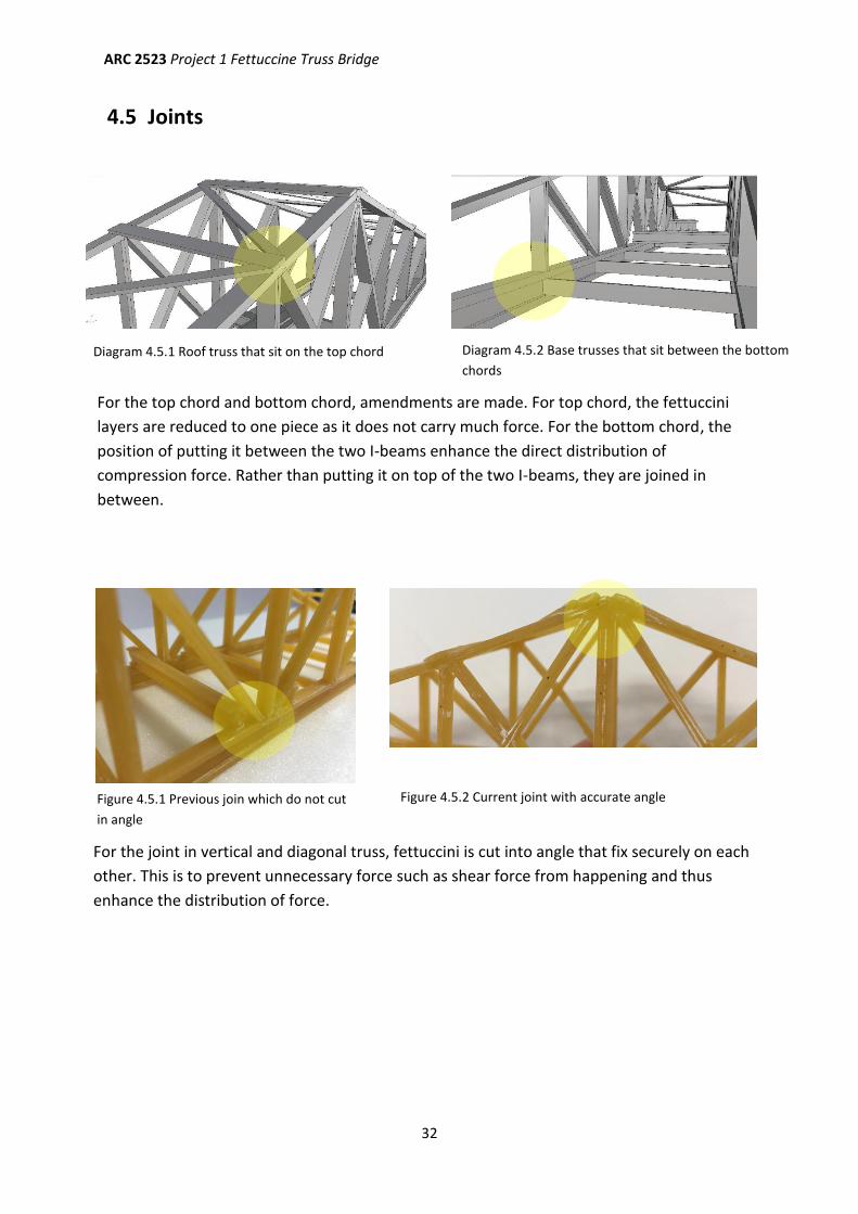
4.5 Joints
For the top chord and bottom chord, amendments are made. For top chord, the fettuccini
layers are reduced to one piece as it does not carry much force. For the bottom chord, the
position of putting it between the two I-beams enhance the direct distribution of
compression force. Rather than putting it on top of the two I-beams, they are joined in
between.
For the joint in vertical and diagonal truss, fettuccini is cut into angle that fix securely on each
other. This is to prevent unnecessary force such as shear force from happening and thus
enhance the distribution of force.
Figure 4.5.1 Previous join which do not cut
in angle
Figure 4.5.2 Current joint with accurate angle
Diagram 4.5.1 Roof truss that sit on the top chord Diagram 4.5.2 Base trusses that sit between the bottom
chords
ARC 2523 Project 1 Fettuccine Truss Bridge
33
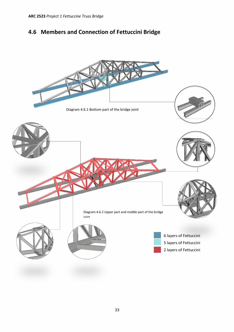
4.6 Members and Connection of Fettuccini Bridge
6 layers of Fettuccini
5 layers of Fettuccini
2 layers of Fettuccini
Diagram 4.6.2 Upper part and middle part of the bridge
joint
Diagram 4.6.1 Bottom part of the bridge joint
ARC 2523 Project 1 Fettuccine Truss Bridge
34
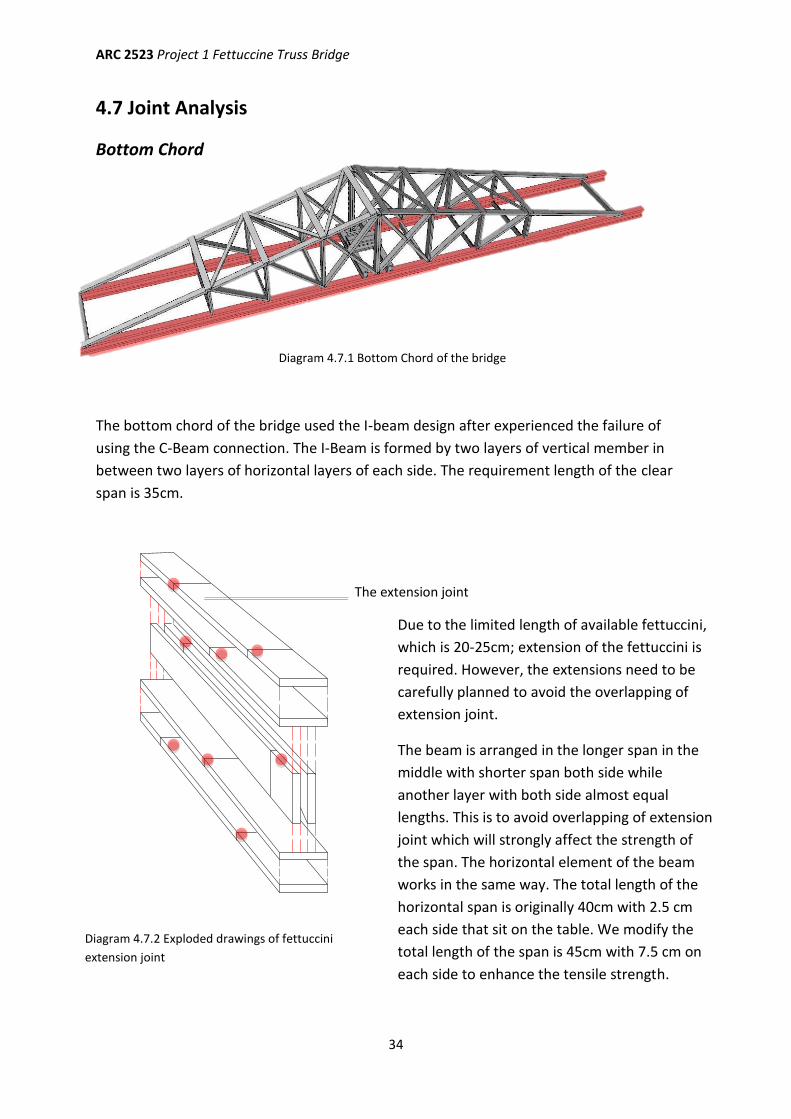
4.7 Joint Analysis
Bottom Chord
The bottom chord of the bridge used the I-beam design after experienced the failure of
using the C-Beam connection. The I-Beam is formed by two layers of vertical member in
between two layers of horizontal layers of each side. The requirement length of the clear
span is 35cm.
Diagram 4.7.1 Bottom Chord of the bridge
The extension joint
Due to the limited length of available fettuccini,
which is 20-25cm; extension of the fettuccini is
required. However, the extensions need to be
carefully planned to avoid the overlapping of
extension joint.
The beam is arranged in the longer span in the
middle with shorter span both side while
another layer with both side almost equal
lengths. This is to avoid overlapping of extension
joint which will strongly affect the strength of
the span. The horizontal element of the beam
works in the same way. The total length of the
horizontal span is originally 40cm with 2.5 cm
each side that sit on the table. We modify the
total length of the span is 45cm with 7.5 cm on
each side to enhance the tensile strength.
Diagram 4.7.2 Exploded drawings of fettuccini
extension joint
ARC 2523 Project 1 Fettuccine Truss Bridge
35
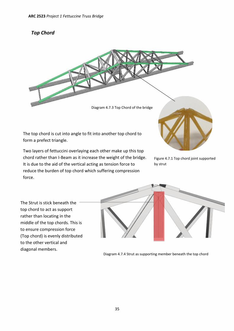
Top Chord
Diagram 4.7.3 Top Chord of the bridge
The top chord is cut into angle to fit into another top chord to
form a prefect triangle.
Two layers of fettuccini overlaying each other make up this top
chord rather than I-Beam as it increase the weight of the bridge.
It is due to the aid of the vertical acting as tension force to
reduce the burden of top chord which suffering compression
force.
The Strut is stick beneath the
top chord to act as support
rather than locating in the
middle of the top chords. This is
to ensure compression force
(Top chord) is evenly distributed
to the other vertical and
diagonal members.
Figure 4.7.1 Top chord joint supported
by strut
Diagram 4.7.4 Strut as supporting member beneath the top chord
ARC 2523 Project 1 Fettuccine Truss Bridge
36
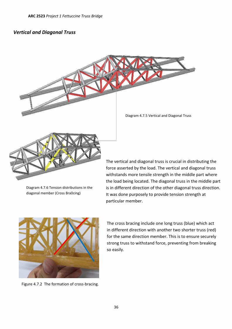
The vertical and diagonal truss is crucial in distributing the
force asserted by the load. The vertical and diagonal truss
withstands more tensile strength in the middle part where
the load being located. The diagonal truss in the middle part
is in different direction of the other diagonal truss direction.
It was done purposely to provide tension strength at
particular member.
The cross bracing include one long truss (blue) which act
in different direction with another two shorter truss (red)
for the same direction member. This is to ensure securely
strong truss to withstand force, preventing from breaking
so easily.
Diagram 4.7.6 Tension distributions in the
diagonal member (Cross Bra0cing)
Figure 4.7.2 The formation of cross-bracing.
Vertical and Diagonal Truss
Diagram 4.7.5 Vertical and Diagonal Truss
ARC 2523 Project 1 Fettuccine Truss Bridge
37
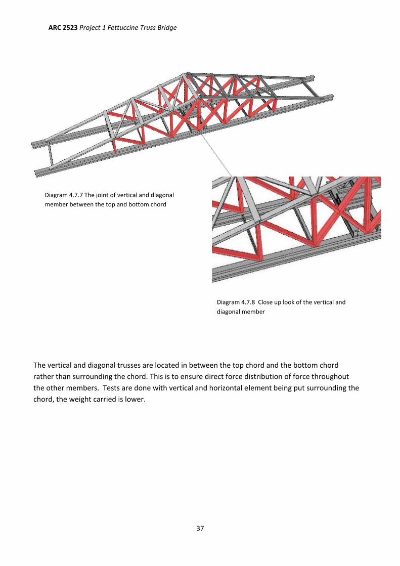
The vertical and diagonal trusses are located in between the top chord and the bottom chord
rather than surrounding the chord. This is to ensure direct force distribution of force throughout
the other members. Tests are done with vertical and horizontal element being put surrounding the
chord, the weight carried is lower.
Diagram 4.7.7 The joint of vertical and diagonal
member between the top and bottom chord
Diagram 4.7.8 Close up look of the vertical and
diagonal member
ARC 2523 Project 1 Fettuccine Truss Bridge
38
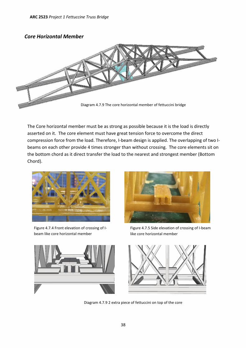
Core Horizontal Member
The Core horizontal member must be as strong as possible because it is the load is directly
asserted on it. The core element must have great tension force to overcome the direct
compression force from the load. Therefore, I-beam design is applied. The overlapping of two I-
beams on each other provide 4 times stronger than without crossing. The core elements sit on
the bottom chord as it direct transfer the load to the nearest and strongest member (Bottom
Chord).
Diagram 4.7.9 The core horizontal member of fettuccini bridge
Figure 4.7.4 Front elevation of crossing of I-
beam like core horizontal member
Figure 4.7.5 Side elevation of crossing of I-beam
like core horizontal member
Diagram 4.7.9 2 extra piece of fettuccini on top of the core
ARC 2523 Project 1 Fettuccine Truss Bridge
39
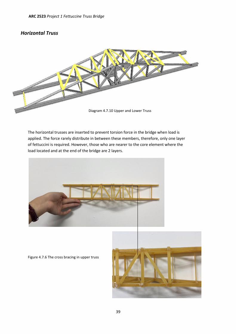
Figure 4.7.6 The cross bracing in upper truss
Horizontal Truss
The horizontal trusses are inserted to prevent torsion force in the bridge when load is
applied. The force rarely distribute in between these members, therefore, only one layer
of fettuccini is required. However, those who are nearer to the core element where the
load located and at the end of the bridge are 2 layers.
Diagram 4.7.10 Upper and Lower Truss
ARC 2523 Project 1 Fettuccine Truss Bridge
40
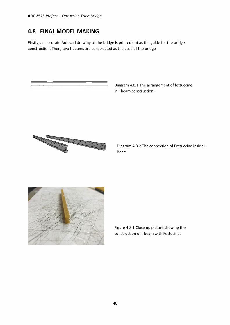
4.8 FINAL MODEL MAKING
Firstly, an accurate Autocad drawing of the bridge is printed out as the guide for the bridge
construction. Then, two I-beams are constructed as the base of the bridge
Diagram 4.8.1 The arrangement of fettuccine
in I-beam construction.
Figure 4.8.1 Close up picture showing the
construction of I-beam with Fettucine.
Diagram 4.8.2 The connection of Fettuccine inside I-
Beam.
ARC 2523 Project 1 Fettuccine Truss Bridge
41
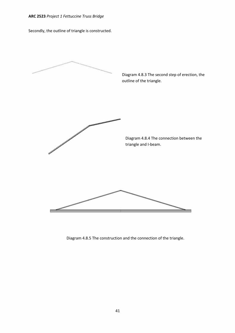
Secondly, the outline of triangle is constructed.
Diagram 4.8.3 The second step of erection, the
outline of the triangle.
Diagram 4.8.5 The construction and the connection of the triangle.
Diagram 4.8.4 The connection between the
triangle and I-beam.
ARC 2523 Project 1 Fettuccine Truss Bridge
42
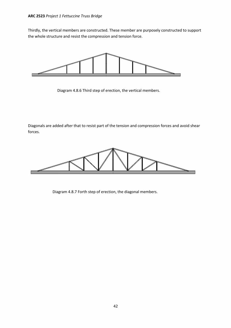
Thirdly, the vertical members are constructed. These member are purposely constructed to support
the whole structure and resist the compression and tension force.
Diagonals are added after that to resist part of the tension and compression forces and avoid shear
forces.
Diagram 4.8.6 Third step of erection, the vertical members.
Diagram 4.8.7 Forth step of erection, the diagonal members.
ARC 2523 Project 1 Fettuccine Truss Bridge
43
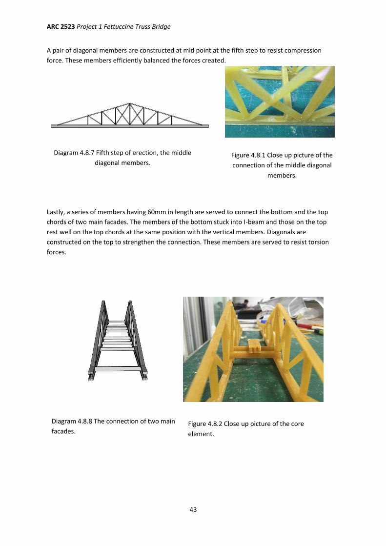
A pair of diagonal members are constructed at mid point at the fifth step to resist compression
force. These members efficiently balanced the forces created.
Lastly, a series of members having 60mm in length are served to connect the bottom and the top
chords of two main facades. The members of the bottom stuck into I-beam and those on the top
rest well on the top chords at the same position with the vertical members. Diagonals are
constructed on the top to strengthen the connection. These members are served to resist torsion
forces.
Diagram 4.8.7 Fifth step of erection, the middle
diagonal members. Figure 4.8.1 Close up picture of the
connection of the middle diagonal
members.
Diagram 4.8.8 The connection of two main
facades. Figure 4.8.2 Close up picture of the core
element.
ARC 2523 Project 1 Fettuccine Truss Bridge
44
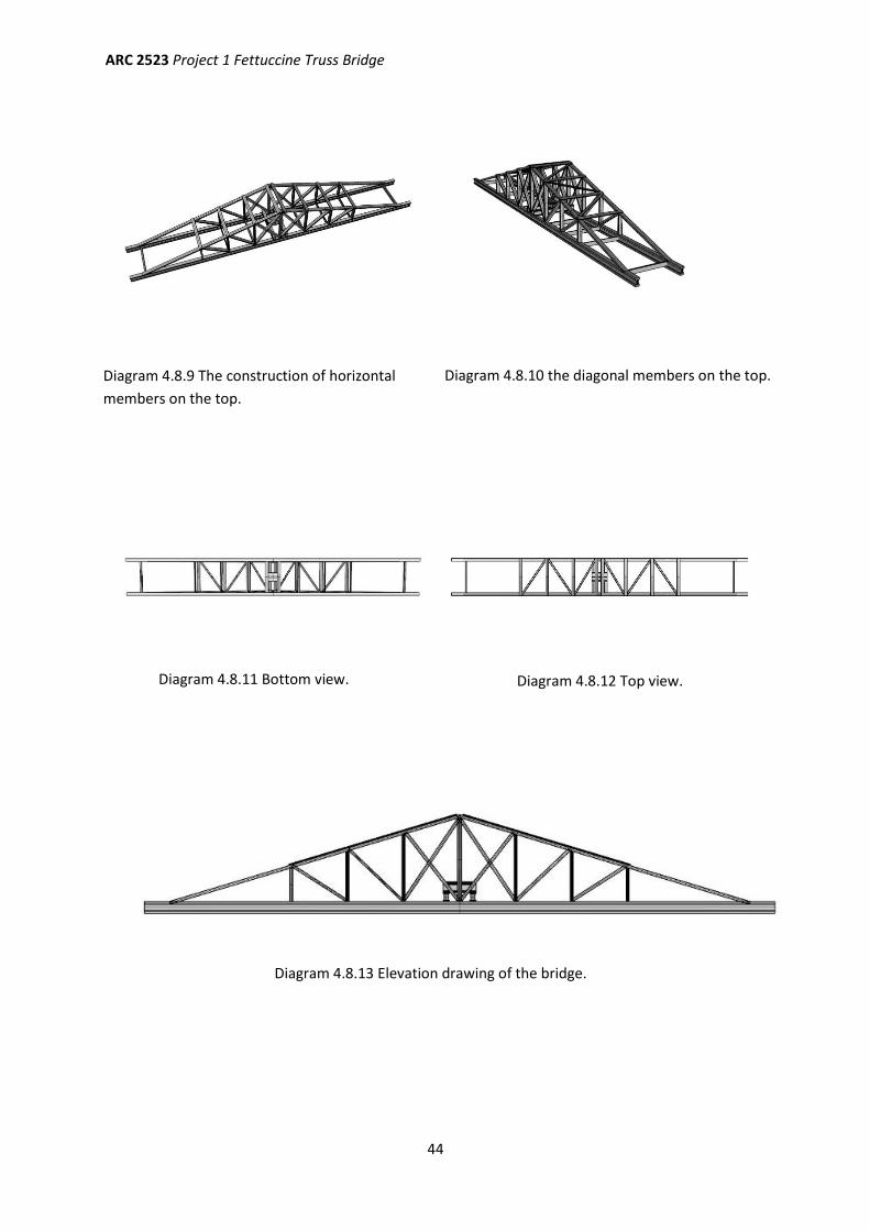
Diagram 4.8.9 The construction of horizontal
members on the top.
Diagram 4.8.10 the diagonal members on the top.
Diagram 4.8.11 Bottom view. Diagram 4.8.12 Top view.
Diagram 4.8.13 Elevation drawing of the bridge.
ARC 2523 Project 1 Fettuccine Truss Bridge
45
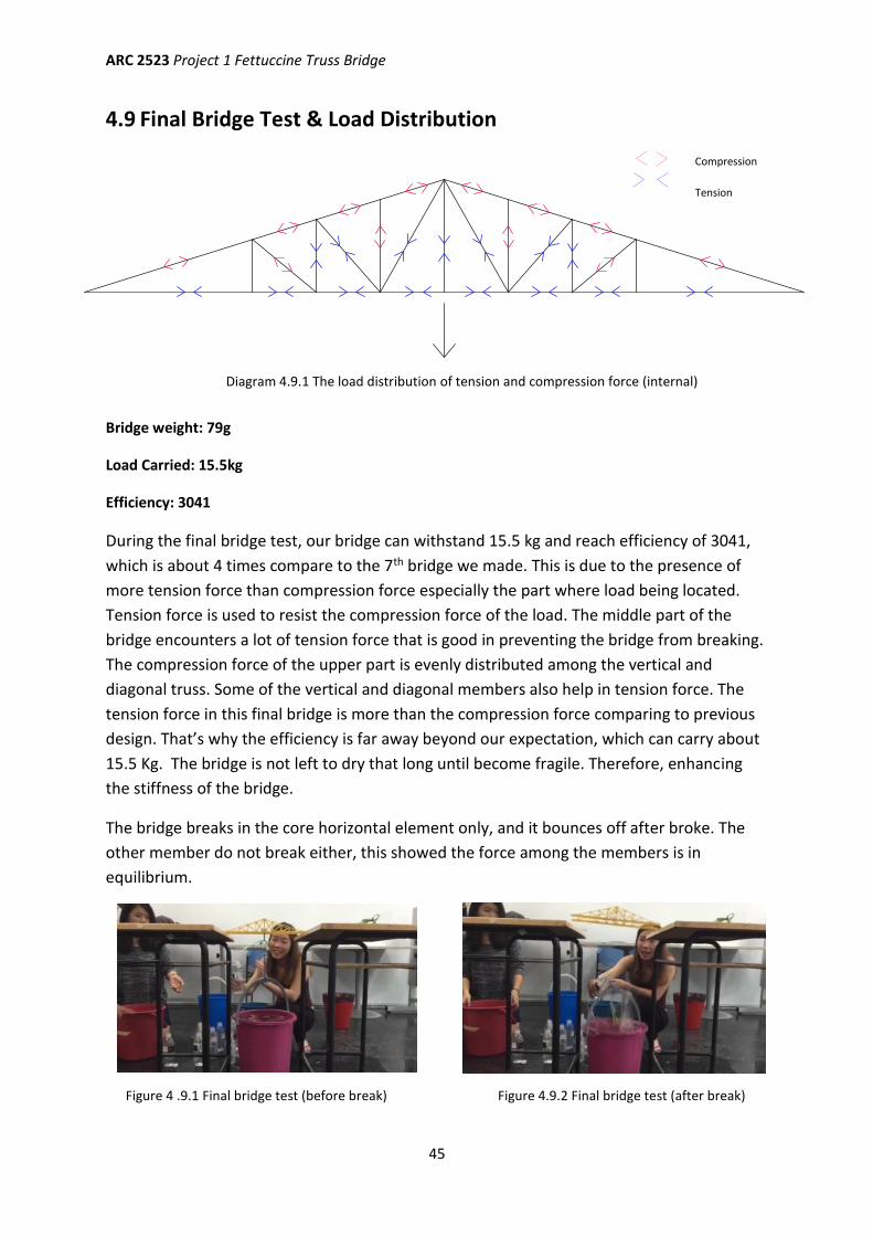
4.9 Final Bridge Test & Load Distribution
Bridge weight: 79g
Load Carried: 15.5kg
Efficiency: 3041
During the final bridge test, our bridge can withstand 15.5 kg and reach efficiency of 3041,
which is about 4 times compare to the 7th bridge we made. This is due to the presence of
more tension force than compression force especially the part where load being located.
Tension force is used to resist the compression force of the load. The middle part of the
bridge encounters a lot of tension force that is good in preventing the bridge from breaking.
The compression force of the upper part is evenly distributed among the vertical and
diagonal truss. Some of the vertical and diagonal members also help in tension force. The
tension force in this final bridge is more than the compression force comparing to previous
design. That’s why the efficiency is far away beyond our expectation, which can carry about
15.5 Kg. The bridge is not left to dry that long until become fragile. Therefore, enhancing
the stiffness of the bridge.
The bridge breaks in the core horizontal element only, and it bounces off after broke. The
other member do not break either, this showed the force among the members is in
equilibrium.
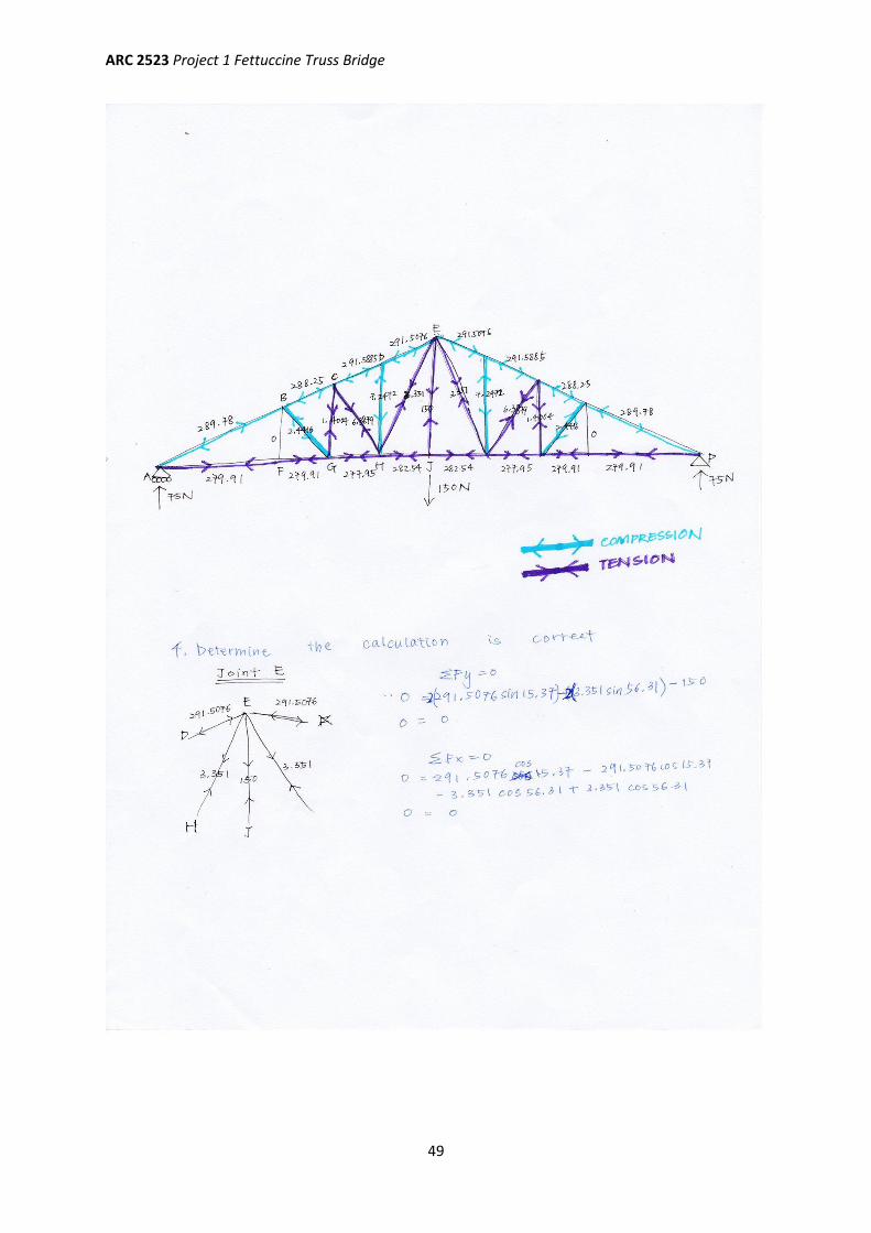
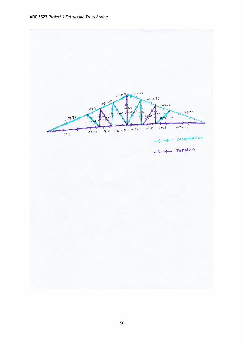
Diagram 4.9.1 The load distribution of tension and compression force (internal)
Figure 4 .9.1 Final bridge test (before break) Figure 4.9.2 Final bridge test (after break)
Compression
Tension
ARC 2523 Project 1 Fettuccine Truss Bridge
46
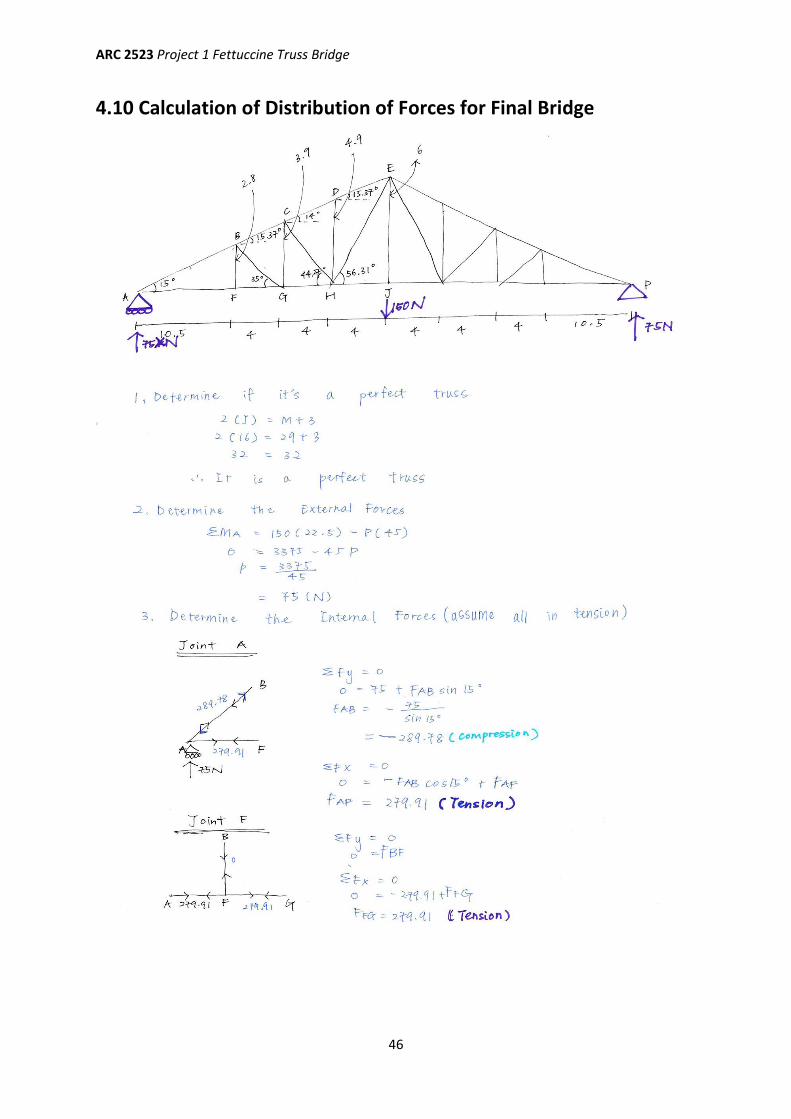
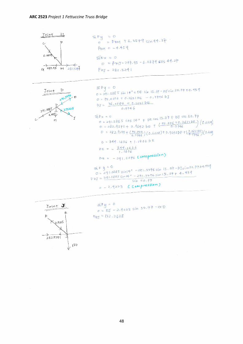
4.10 Calculation of Distribution of Forces for Final Bridge
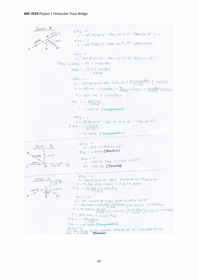
ARC 2523 Project 1 Fettuccine Truss Bridge
47
ARC 2523 Project 1 Fettuccine Truss Bridge
48
ARC 2523 Project 1 Fettuccine Truss Bridge
49
ARC 2523 Project 1 Fettuccine Truss Bridge
50
ARC 2523 Project 1 Fettuccine Truss Bridge
51
CHAPTER 5: Reference
Patent US529220 - Truss-bridge.(1894, November 13). Retrieved Oct 1, 2015, from
http://www.google.com/patents/US529220
Ching, Francis D.K (2008) Building Construction Illustrated Fourth Edition. New Jersey: John
Wiley & Sons, Inc.
Lamb, Robert, and Michael Morrissey. "How Bridges Work" (01 April 2000). Retrieved Oct 1,
2015, from http://science.howstuffworks.com/engineering/civil/bridge.html
ARC 2523 Project 1 Fettuccine Truss Bridge
52
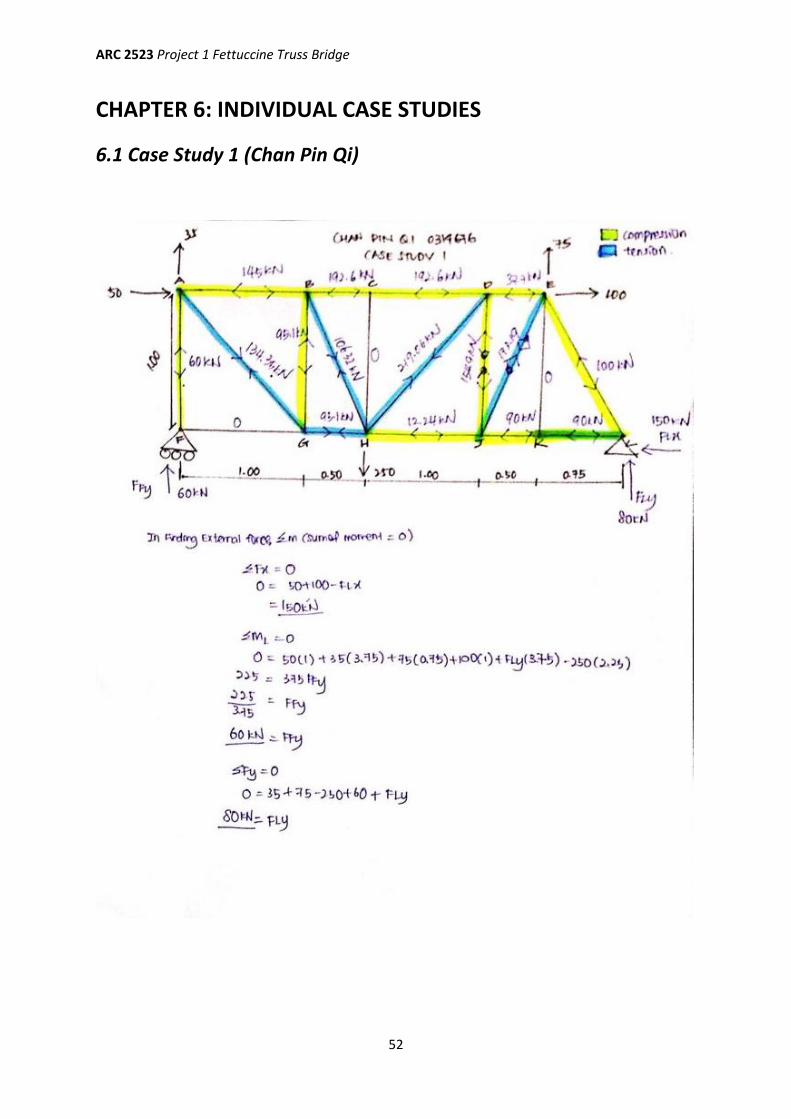
CHAPTER 6: INDIVIDUAL CASE STUDIES
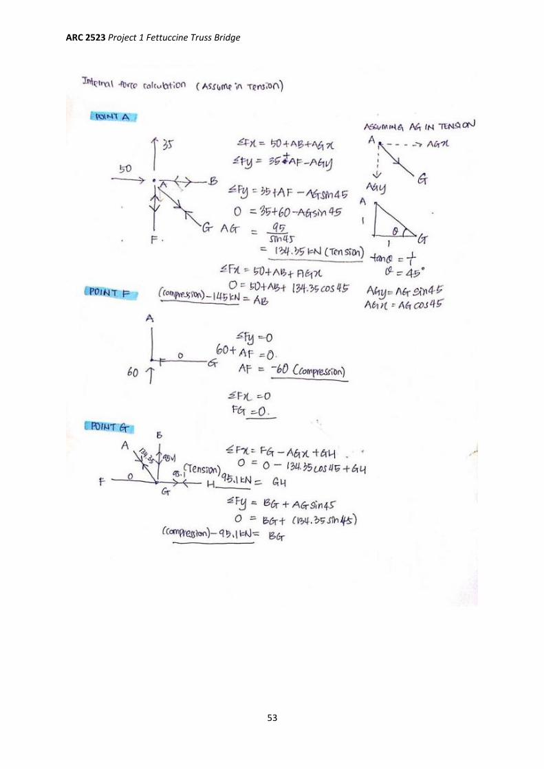
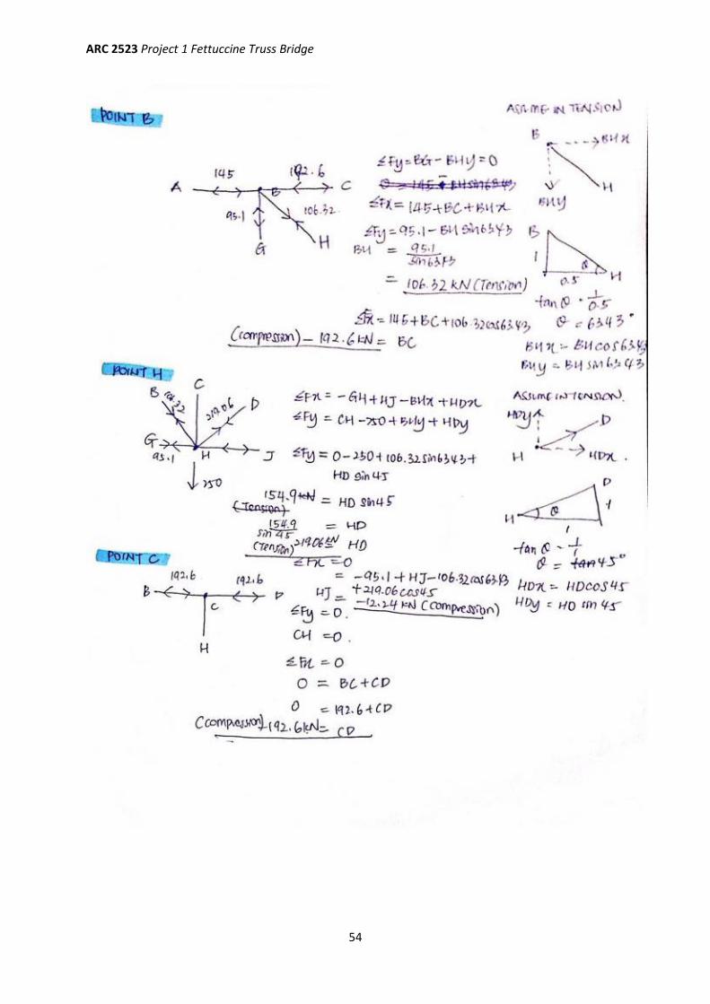
6.1 Case Study 1 (Chan Pin Qi)
ARC 2523 Project 1 Fettuccine Truss Bridge
53
ARC 2523 Project 1 Fettuccine Truss Bridge
54
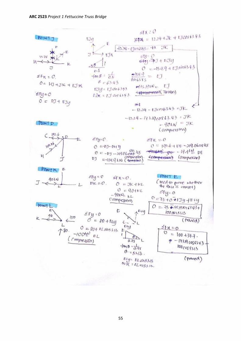
ARC 2523 Project 1 Fettuccine Truss Bridge
55
ARC 2523 Project 1 Fettuccine Truss Bridge
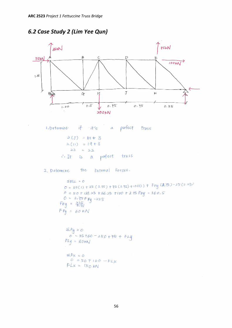
56
6.2 Case Study 2 (Lim Yee Qun)
ARC 2523 Project 1 Fettuccine Truss Bridge
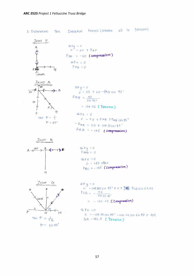
57
ARC 2523 Project 1 Fettuccine Truss Bridge
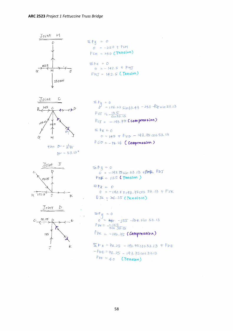
58
ARC 2523 Project 1 Fettuccine Truss Bridge
59
ARC 2523 Project 1 Fettuccine Truss Bridge
60
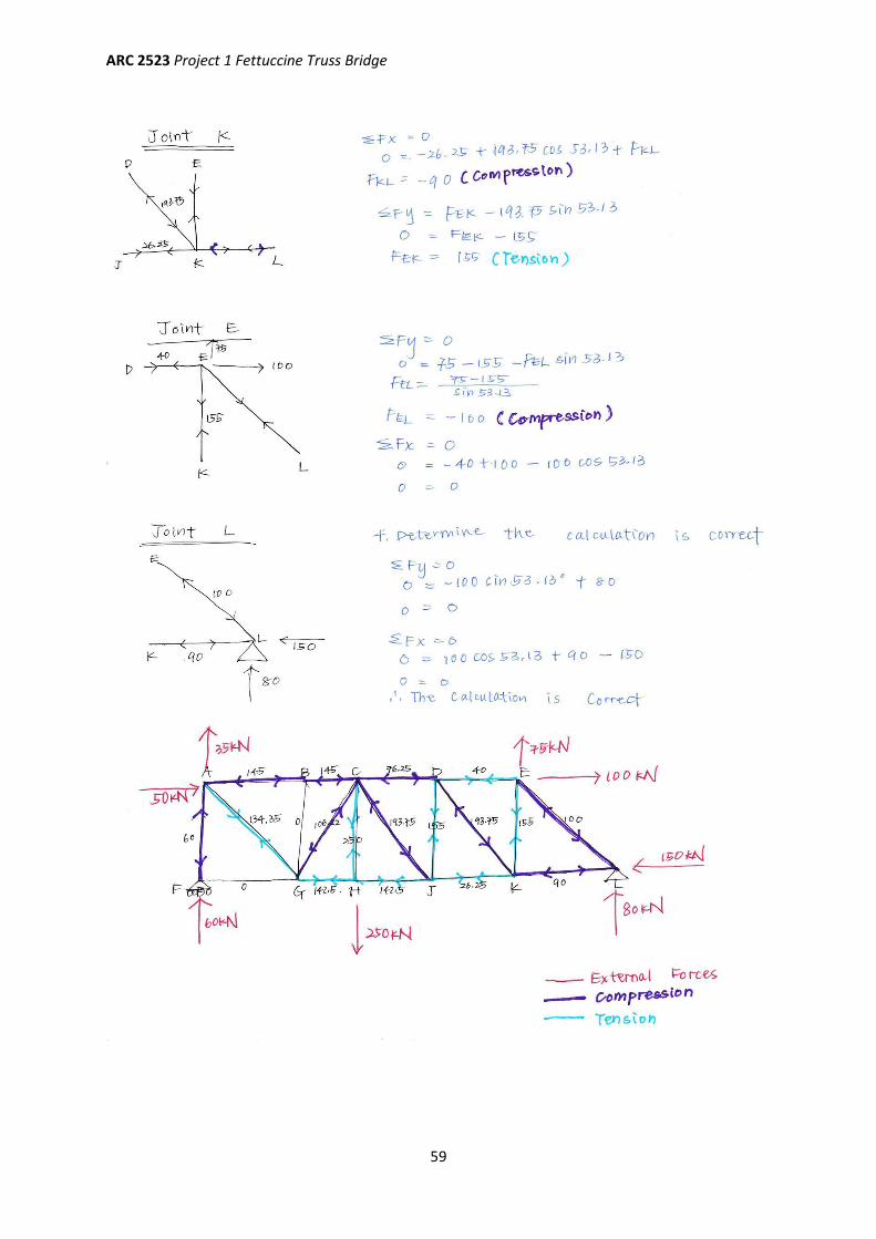
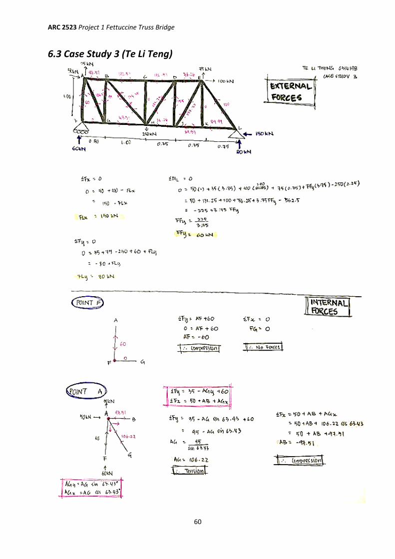
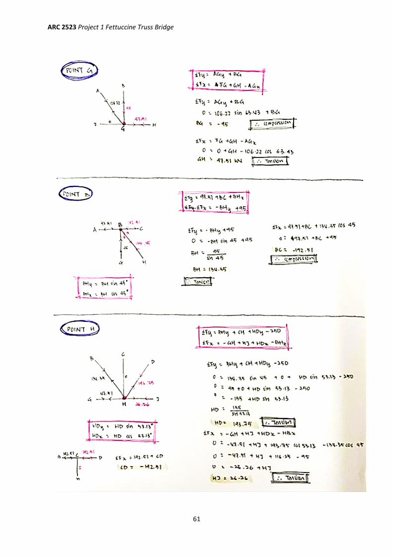
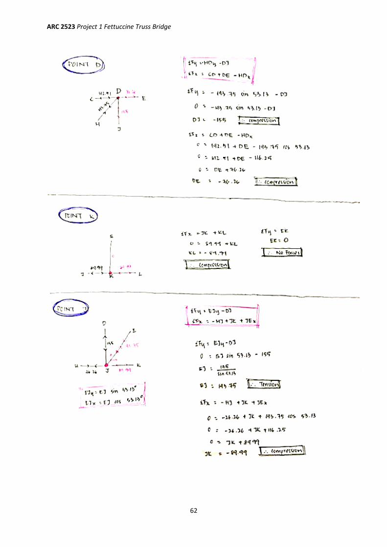
6.3 Case Study 3 (Te Li Teng)
ARC 2523 Project 1 Fettuccine Truss Bridge
61
ARC 2523 Project 1 Fettuccine Truss Bridge
62
ARC 2523 Project 1 Fettuccine Truss Bridge
63
ARC 2523 Project 1 Fettuccine Truss Bridge
64
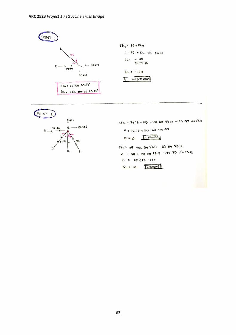
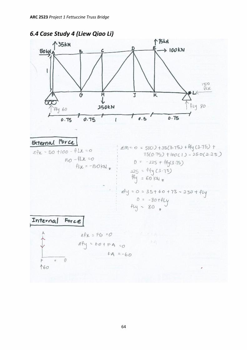
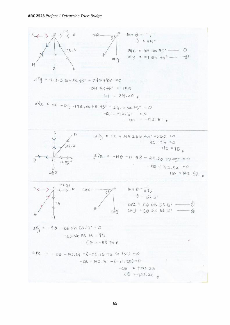
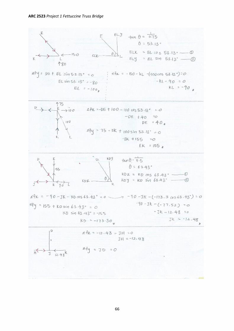
6.4 Case Study 4 (Liew Qiao Li)
ARC 2523 Project 1 Fettuccine Truss Bridge
65
ARC 2523 Project 1 Fettuccine Truss Bridge
66
ARC 2523 Project 1 Fettuccine Truss Bridge
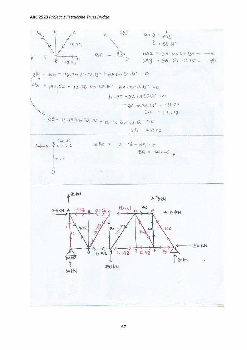
67
ARC 2523 Project 1 Fettuccine Truss Bridge
68
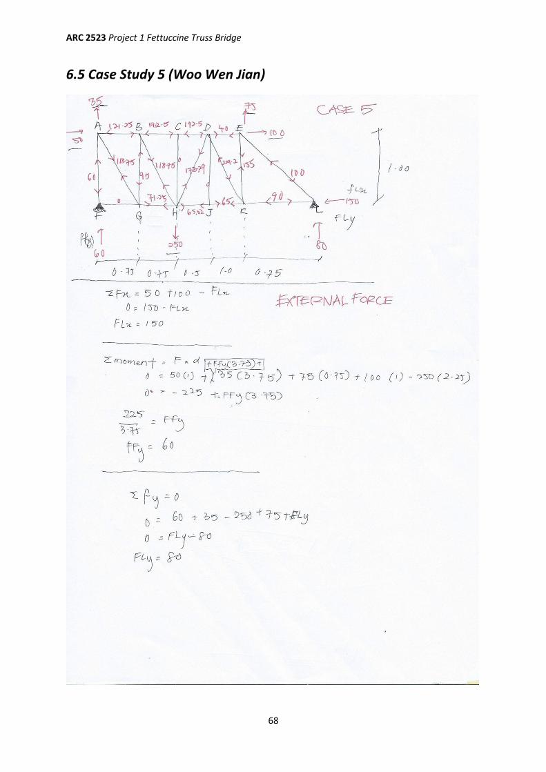
6.5 Case Study 5 (Woo Wen Jian)
ARC 2523 Project 1 Fettuccine Truss Bridge
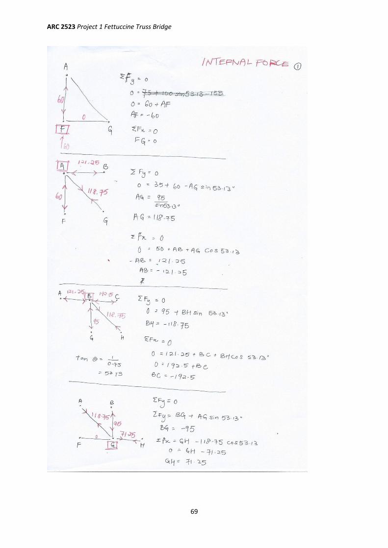
69
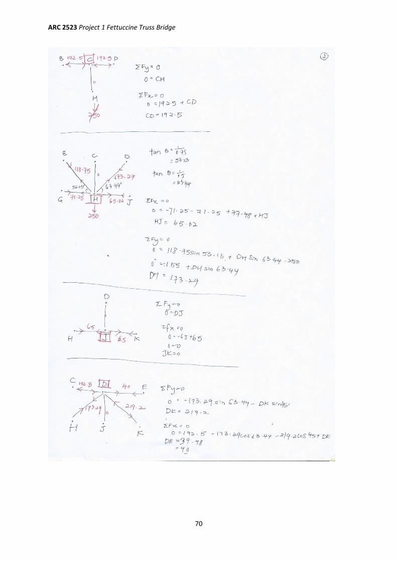
ARC 2523 Project 1 Fettuccine Truss Bridge
70
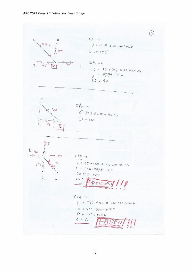
ARC 2523 Project 1 Fettuccine Truss Bridge
71

![Building Structure [ARC 2522] Project 1](https://img.pdfslide.net/doc/110x75/568c53931a28ab4916bb5ea0/building-structure-arc-2522-project-1.jpg)


![[GROUP] Building Structure Project](https://img.pdfslide.net/doc/110x75/5695d0861a28ab9b0292cee5/group-building-structure-project.jpg)
