Embed Size (px)
Citation preview
20.1
Chapter 20
Network Layer:
Internet Protocol
Copyright © The McGraw-Hill Companies, Inc. Permission required for reproduction or display.
20.2
20-1 INTERNETWORKING
In this section, we discuss internetworking, connecting
networks together to make an internetwork or an
internet.
Need for Network Layer
Internet as a Datagram Network
Internet as a Connectionless Network
Topics discussed in this section:
20.3
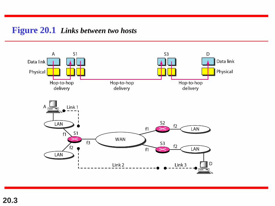
Figure 20.1 Links between two hosts
20.4
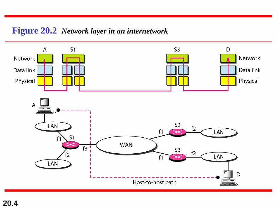
Figure 20.2 Network layer in an internetwork
20.5
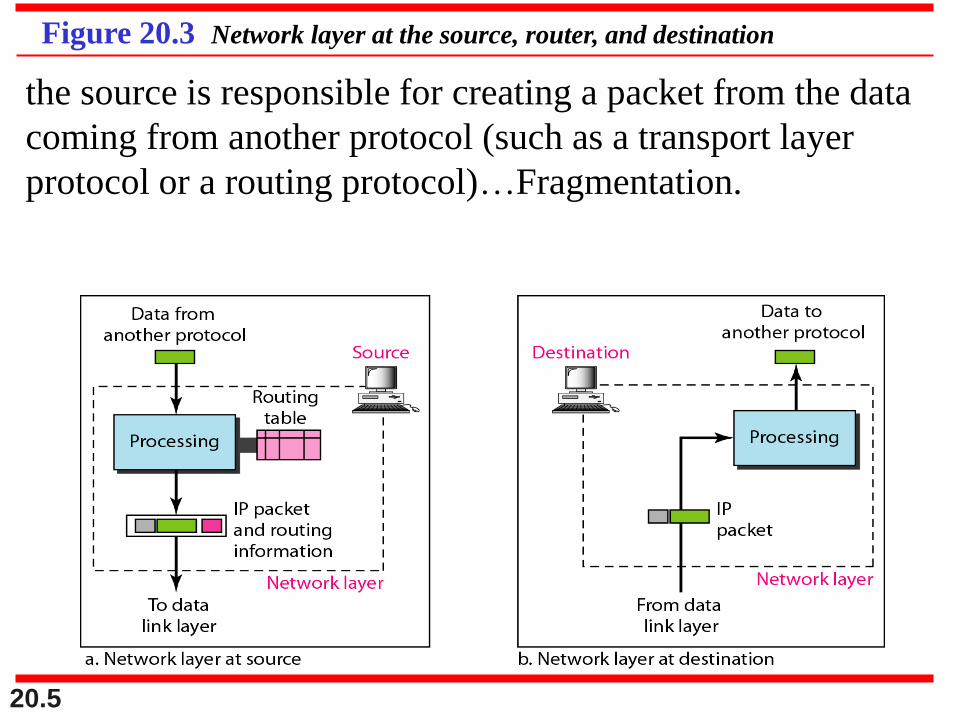
Figure 20.3 Network layer at the source, router, and destination
the source is responsible for creating a packet from the data
coming from another protocol (such as a transport layer
protocol or a routing protocol)…Fragmentation.
20.6
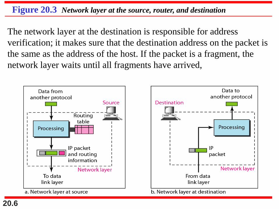
Figure 20.3 Network layer at the source, router, and destination
The network layer at the destination is responsible for address
verification; it makes sure that the destination address on the packet is
the same as the address of the host. If the packet is a fragment, the
network layer waits until all fragments have arrived,
20.7
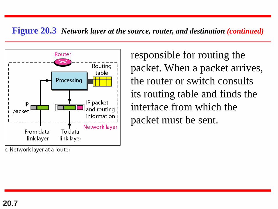
Figure 20.3 Network layer at the source, router, and destination (continued)
responsible for routing the
packet. When a packet arrives,
the router or switch consults
its routing table and finds the
interface from which the
packet must be sent.
20.8
Switching at the network layer in the
Internet uses the datagram approach to
packet switching.
Note
20.9
Communication at the network layer in
the Internet is connectionless.
Note
20.10
20-2 IPv4
The Internet Protocol version 4 (IPv4) is the delivery
mechanism used by the TCP/IP protocols.
Datagram
Fragmentation
Checksum
Options
Topics discussed in this section:
20.11
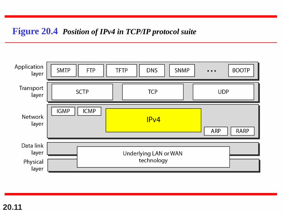
Figure 20.4 Position of IPv4 in TCP/IP protocol suite
20.12
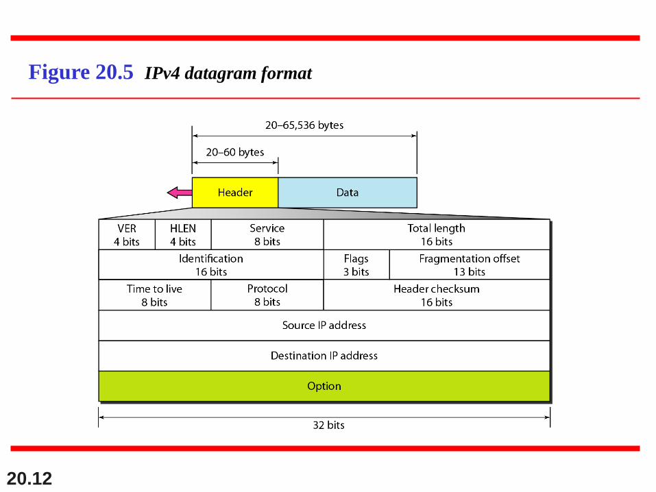
Figure 20.5 IPv4 datagram format
20.13
Header length (HLEN). This 4-bit field defines the total
length of the datagram header in 4-byte words. This
field is needed because the length of the header is
variable (between 20 and 60 bytes). When there are no
options, the header length is 20 bytes, and the value of
this field is 5 (5 x 4 = 20). When the option field is at its
maximum size, the value of this field is 15 (15 x 4 = 60).
Header length (HLEN)
20.14
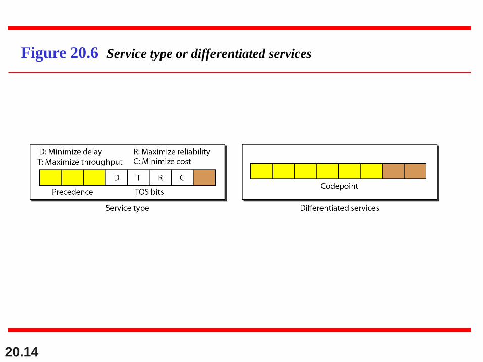
Figure 20.6 Service type or differentiated services
20.15
The precedence subfield was part of
version 4, but never used.
Note
20.16
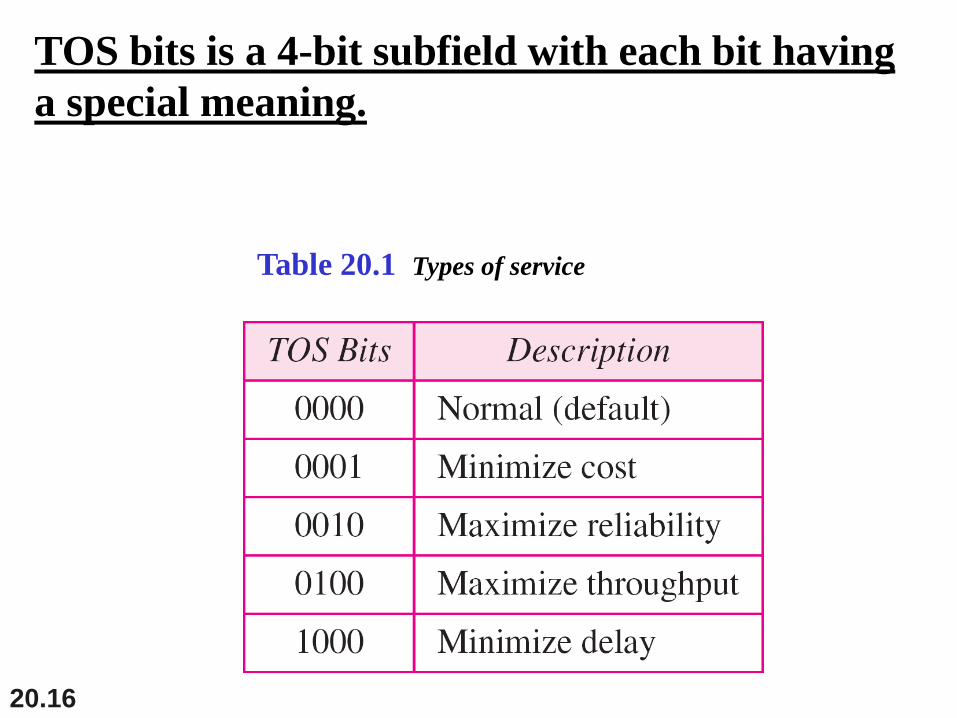
Table 20.1 Types of service
TOS bits is a 4-bit subfield with each bit having
a special meaning.
20.17
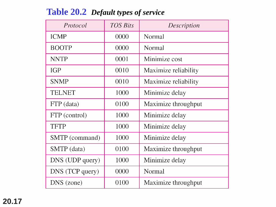
Table 20.2 Default types of service
20.18
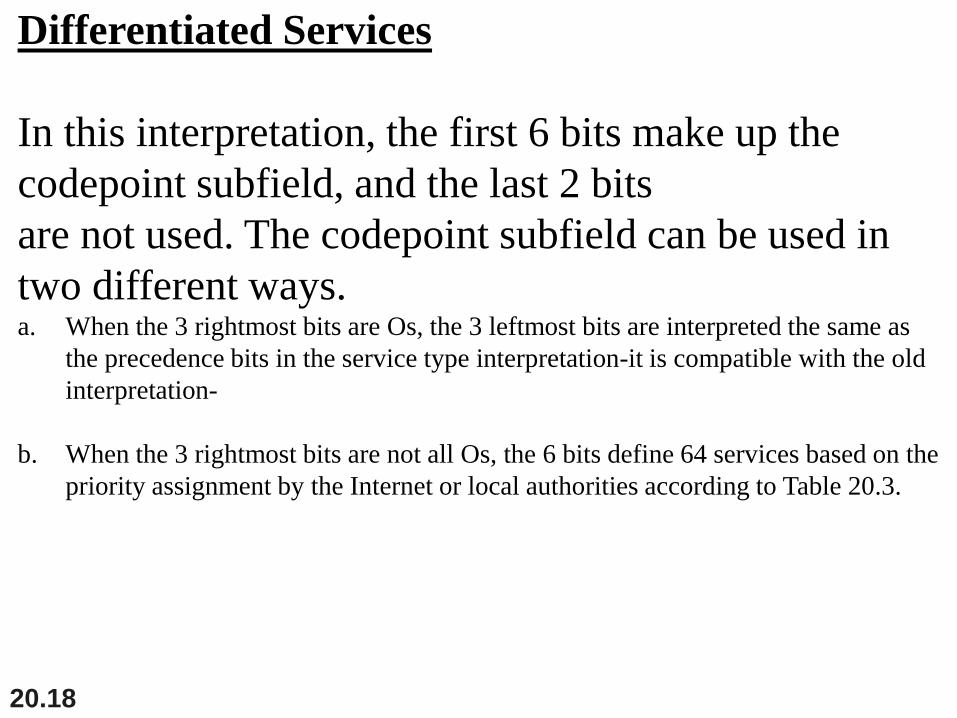
Differentiated Services
In this interpretation, the first 6 bits make up the
codepoint subfield, and the last 2 bits
are not used. The codepoint subfield can be used in
two different ways.a. When the 3 rightmost bits are Os, the 3 leftmost bits are interpreted the same as
the precedence bits in the service type interpretation-it is compatible with the old
interpretation-
b. When the 3 rightmost bits are not all Os, the 6 bits define 64 services based on the
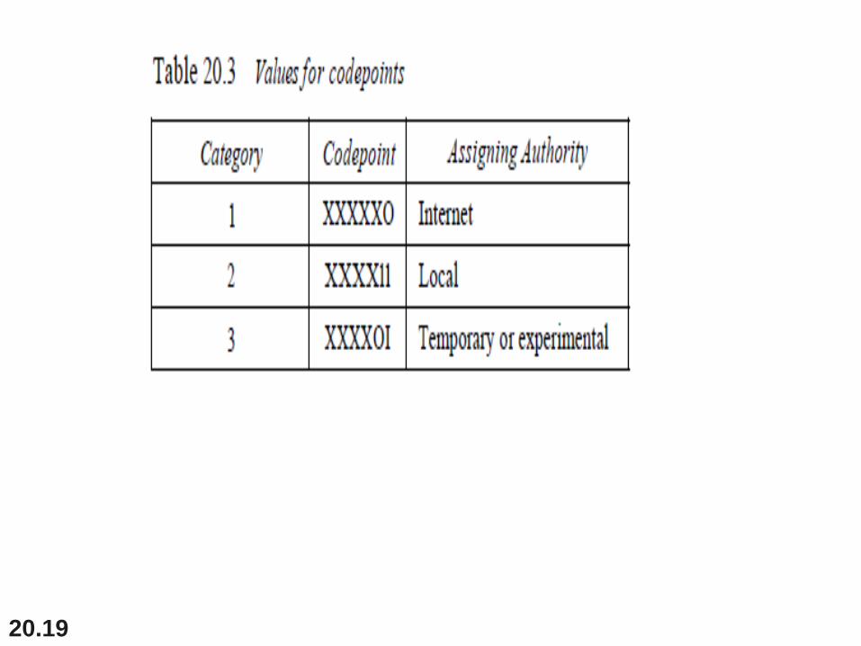
priority assignment by the Internet or local authorities according to Table 20.3.
20.19
20.20
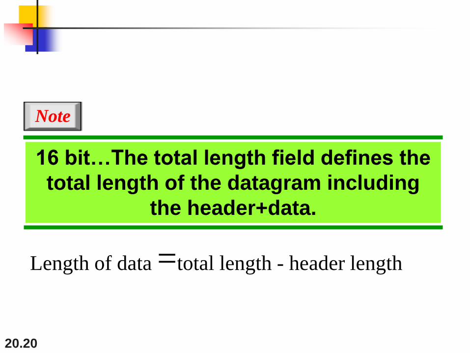
16 bit…The total length field defines the
total length of the datagram including
the header+data.
Note
Length of data =total length - header length
20.21
some physical networks are not able to
encapsulate a datagram of 65,535 bytes
in their frames. The datagram must be
fragmented to be able to pass through
those networks.
Note
20.22
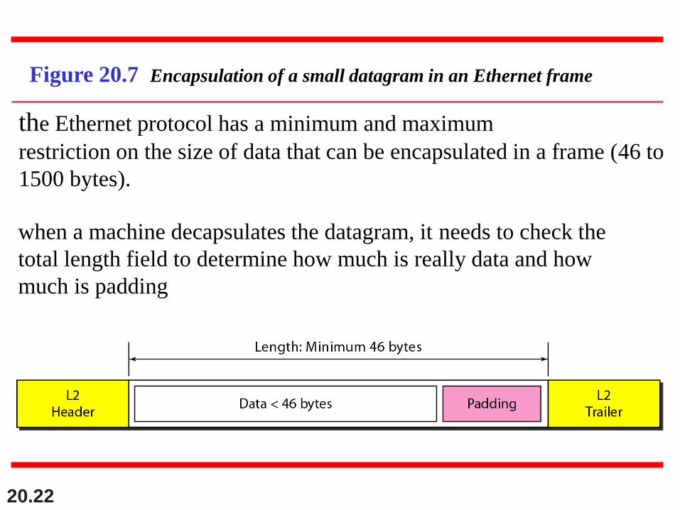
Figure 20.7 Encapsulation of a small datagram in an Ethernet frame
the Ethernet protocol has a minimum and maximum
restriction on the size of data that can be encapsulated in a frame (46 to
1500 bytes).
when a machine decapsulates the datagram, it needs to check the
total length field to determine how much is really data and how
much is padding
20.23
•Identification, flag and Fragmentation offset: This fields
is used in fragmentation.
•Time to live: A datagram has a limited lifetime in its
travel through an internet. The datagram was discarded
when the value became zero.
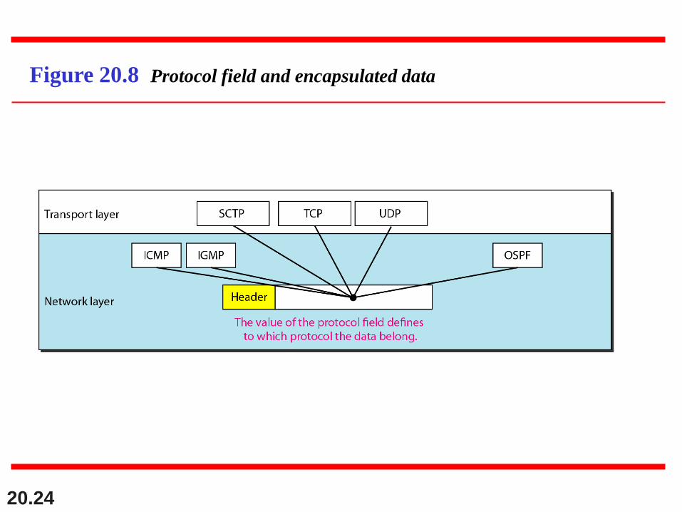
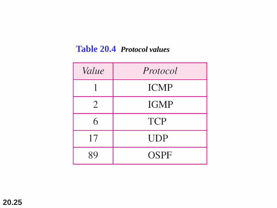
•Protocol: This 8-bit field defines the higher-level protocol
that uses the services of
the IPv4 layer.
20.24
Figure 20.8 Protocol field and encapsulated data
20.25
Table 20.4 Protocol values
20.26
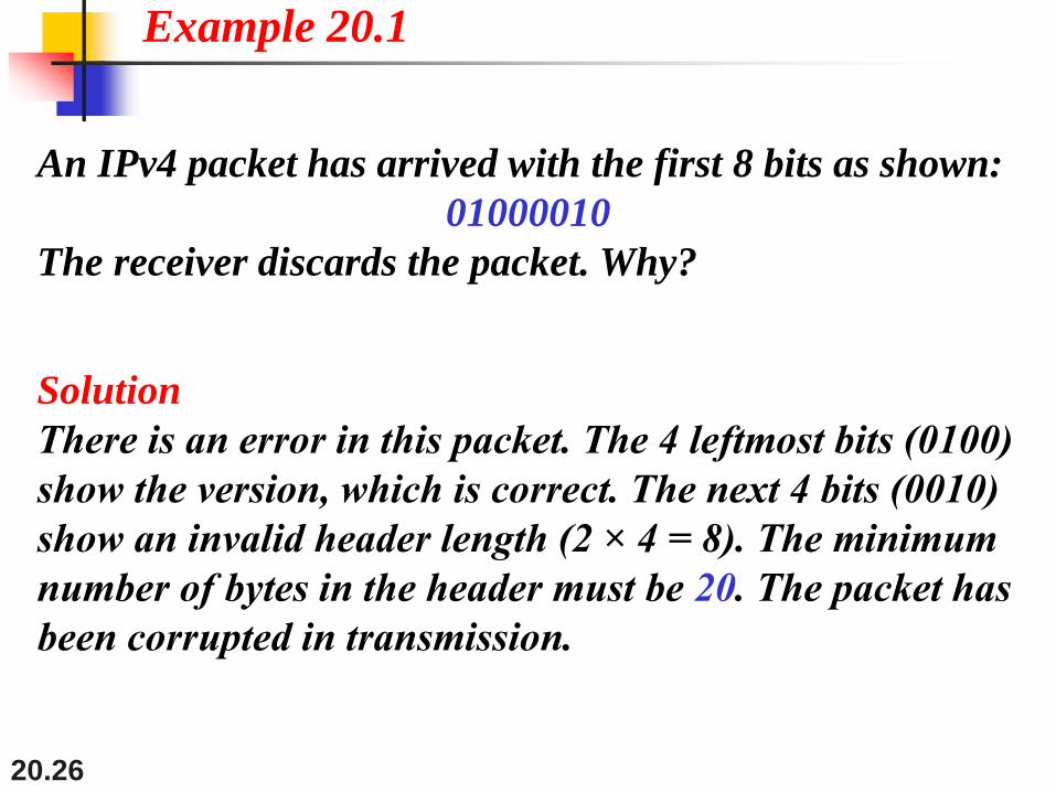
An IPv4 packet has arrived with the first 8 bits as shown:
01000010
The receiver discards the packet. Why?
Solution
There is an error in this packet. The 4 leftmost bits (0100)
show the version, which is correct. The next 4 bits (0010)
show an invalid header length (2 × 4 = 8). The minimum
number of bytes in the header must be 20. The packet has
been corrupted in transmission.
Example 20.1
20.27
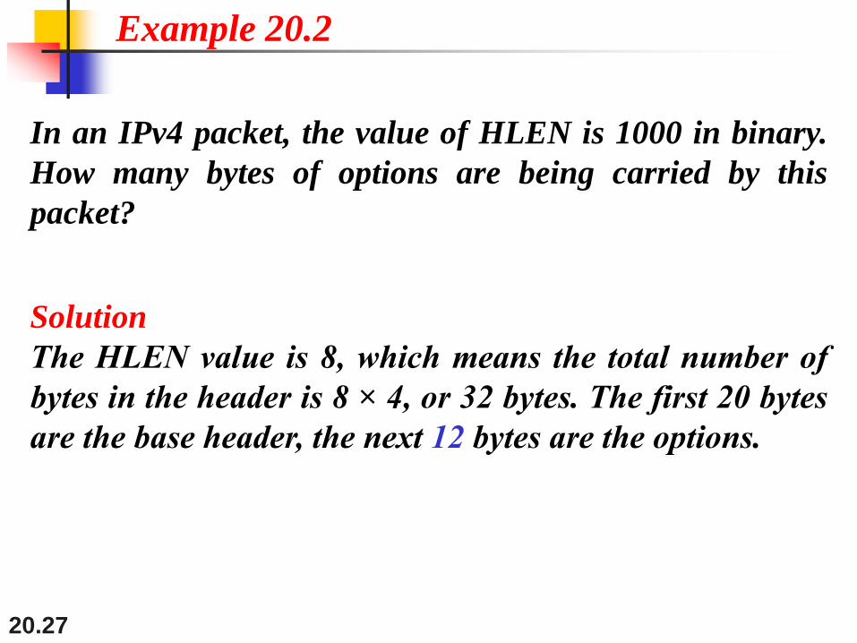
In an IPv4 packet, the value of HLEN is 1000 in binary.
How many bytes of options are being carried by this
packet?
Solution
The HLEN value is 8, which means the total number of
bytes in the header is 8 × 4, or 32 bytes. The first 20 bytes
are the base header, the next 12 bytes are the options.
Example 20.2
20.28
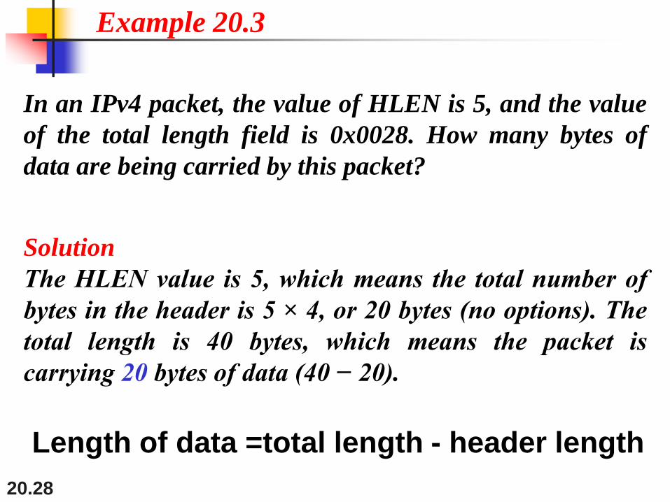
In an IPv4 packet, the value of HLEN is 5, and the value
of the total length field is 0x0028. How many bytes of
data are being carried by this packet?
Solution
The HLEN value is 5, which means the total number of
bytes in the header is 5 × 4, or 20 bytes (no options). The
total length is 40 bytes, which means the packet is
carrying 20 bytes of data (40 − 20).
Example 20.3
Length of data =total length - header length
20.29
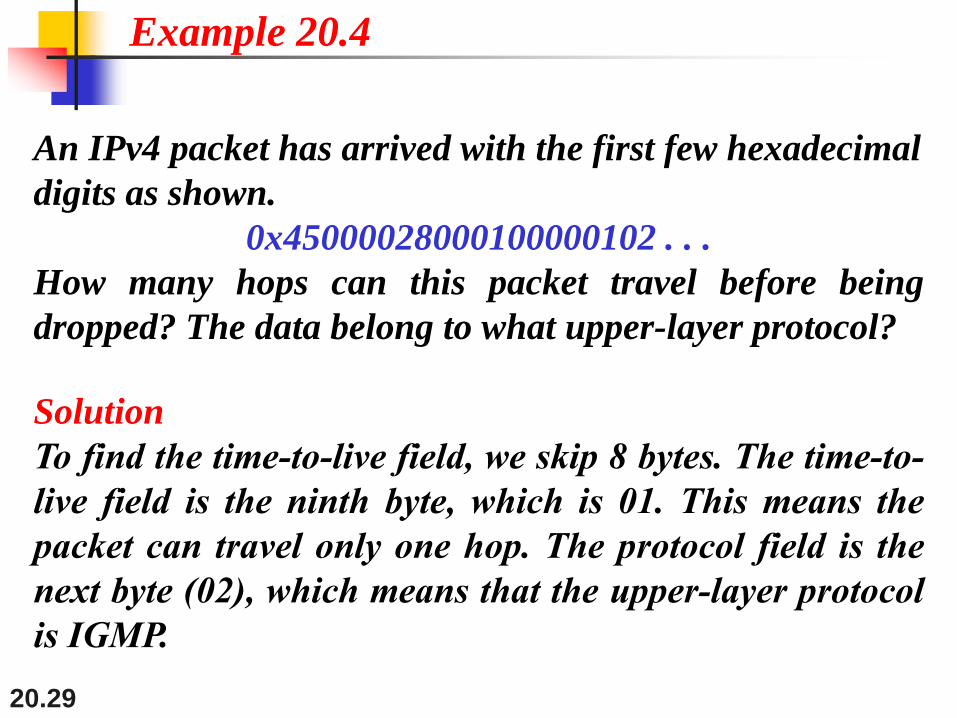
An IPv4 packet has arrived with the first few hexadecimal
digits as shown.
0x45000028000100000102 . . .
How many hops can this packet travel before being
dropped? The data belong to what upper-layer protocol?
Solution
To find the time-to-live field, we skip 8 bytes. The time-to-
live field is the ninth byte, which is 01. This means the
packet can travel only one hop. The protocol field is the
next byte (02), which means that the upper-layer protocol
is IGMP.
Example 20.4
20.30
Fragmentation
•A datagram can travel through different networks. Each
router en-de-capsulates the IPv4 datagram from the frame
it receives.
•The format and size of the received frame depend on the
protocol used by the physical network.
•One of the fields defined in the format is the maximum
size of the data field. - the total size of the datagram must
be less than this maximum size-

20.31
Figure 20.9 Maximum transfer unit (MTU)
To make the IPv4 protocol independent of the physical network,
the designers decided to make the maximum length of the IPv4
datagram equal to 65,535 bytes.
20.32
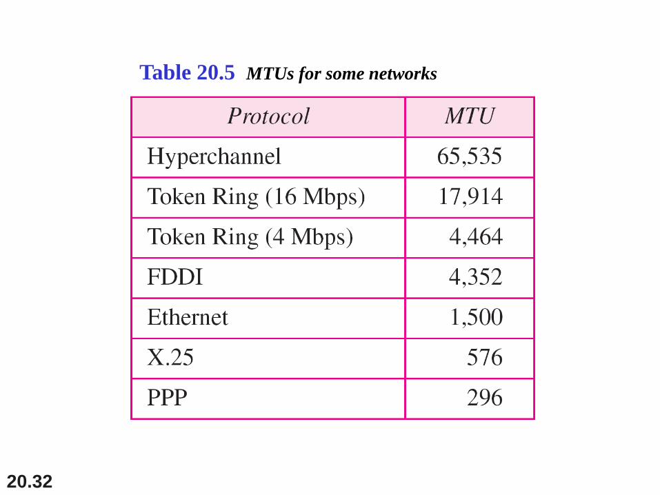
Table 20.5 MTUs for some networks
20.33
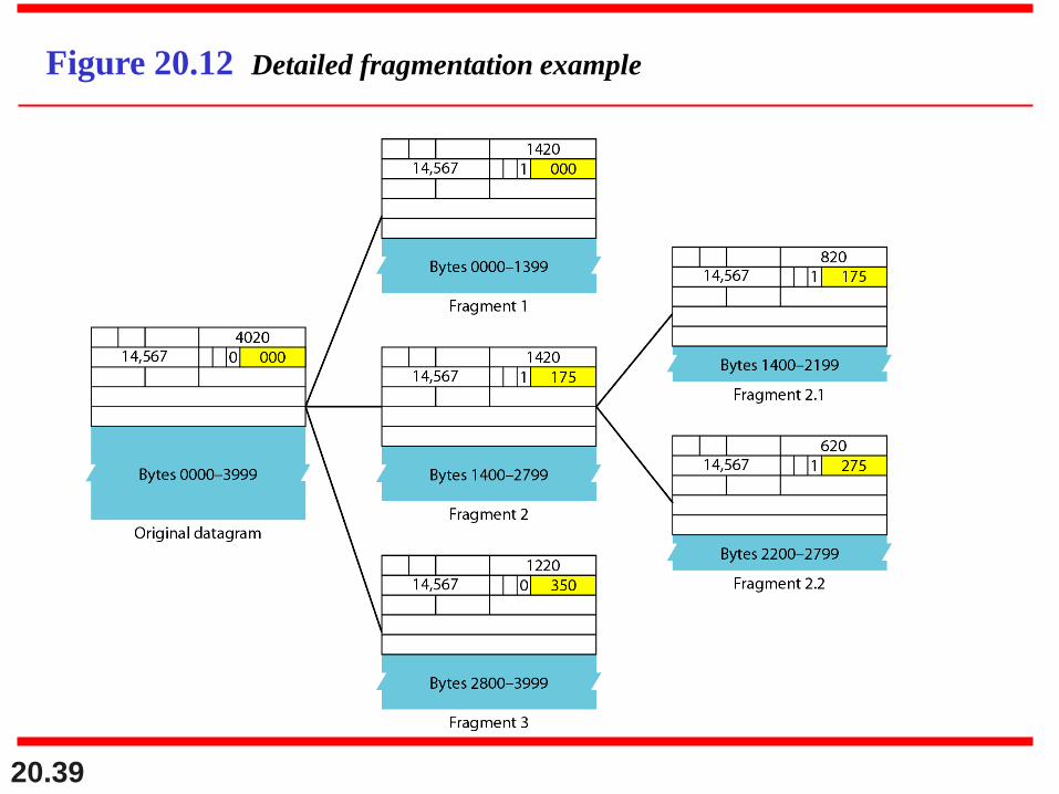
Fragmentation
•When a datagram is fragmented, each fragment has its own header
with most of the fields repeated, but with some changed.
• A Datagram can be fragmented several times before it reaches the
final destination.
•Whereas the fragmented datagram can travel through different
routes.
•All the fragments belonging to the same datagram should finally
arrive at the destination host.
20.34
Fields Related to Fragmentation
Identification:• 16 bits Uniquely define in all fragments.
•To guarantee uniqueness, the IPv4 protocol uses a counter to
label the datagrams.
•The counter is initialized to a positive number. When the IPv4
protocol sends a datagram, it copies the current value
of the counter to the identification field and increments the
counter by'~ 1.
20.35
Fields Related to Fragmentation
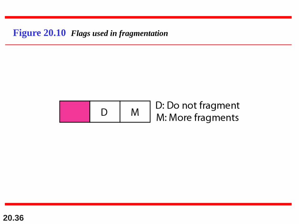
Flags:• 3-bit field. The first bit is reserved. The second bit is called the
do not-fragment bit.•If its value is 1, the machine must not fragment the datagram.
•If its value is 0, the datagram can be fragmented if necessary.
•Third bit is called the more fragment bit. •If its value is 1, it means the datagram is not the last fragment.
•If its value is 0, it means this is the last or only fragment
20.36
Figure 20.10 Flags used in fragmentation
20.37
Fields Related to Fragmentation
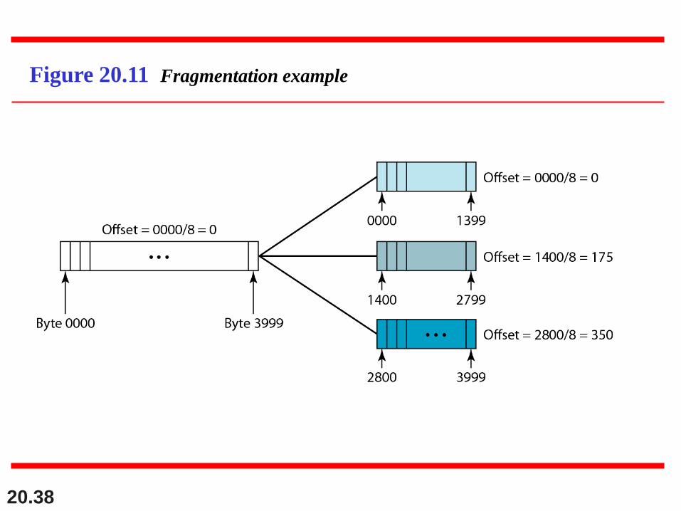
Fragmentation offset.:13-bit field. shows the relative position of this fragment
with respect to the whole datagram.
Measured in units of 8 bytes. Figure 20.11 shows a
datagram with a data size of 4000 bytes fragmented into
three fragments.
20.38
Figure 20.11 Fragmentation example
20.39
Figure 20.12 Detailed fragmentation example
20.40
A packet has arrived with an M bit value of 0. Is this the
first fragment, the last fragment, or a middle fragment?
Do we know if the packet was fragmented?
Solution
If the M bit is 0, it means that there are no more
fragments; the fragment is the last one. However, we
cannot say if the original packet was fragmented or not. A
non-fragmented packet is considered the last fragment.
Example 20.5
20.41
A packet has arrived with an M bit value of 1. Is this the
first fragment, the last fragment, or a middle fragment?
Do we know if the packet was fragmented?
Solution
If the M bit is 1, it means that there is at least one more
fragment. This fragment can be the first one or a middle
one, but not the last one. We don’t know if it is the first
one or a middle one; we need more information (the
value of the fragmentation offset).
Example 20.6
20.42
A packet has arrived with an M bit value of 1 and a
fragmentation offset value of 0. Is this the first fragment,
the last fragment, or a middle fragment?
Solution
Because the M bit is 1, it is either the first fragment or a
middle one. Because the offset value is 0, it is the first
fragment.
Example 20.7
20.43
A packet has arrived in which the offset value is 100.
What is the number of the first byte? Do we know the
number of the last byte?
Solution
To find the number of the first byte, we multiply the offset
value by 8. This means that the first byte number is 800.
We cannot determine the number of the last byte unless
we know the length.
Example 20.8
20.44
A packet has arrived in which the offset value is 100, the
value of HLEN is 5, and the value of the total length field
is 100. What are the numbers of the first byte and the last
byte?
Solution
The first byte number is 100 × 8 = 800. The total length is
100 bytes, and the header length is 20 bytes (5 × 4), which
means that there are 80 bytes in this datagram. If the first
byte number is 800, the last byte number must be 879.
Example 20.9
20.45
Checksum
•Principles. First, the value of the checksum field is set to O.
Then the entire header is divided into 16-bit sections and added
together. The result (sum) is complemented and inserted into the
checksum field.
•The checksum in the IPv4 packet covers only the header, not the
data. There are good reasons for this.
20.46
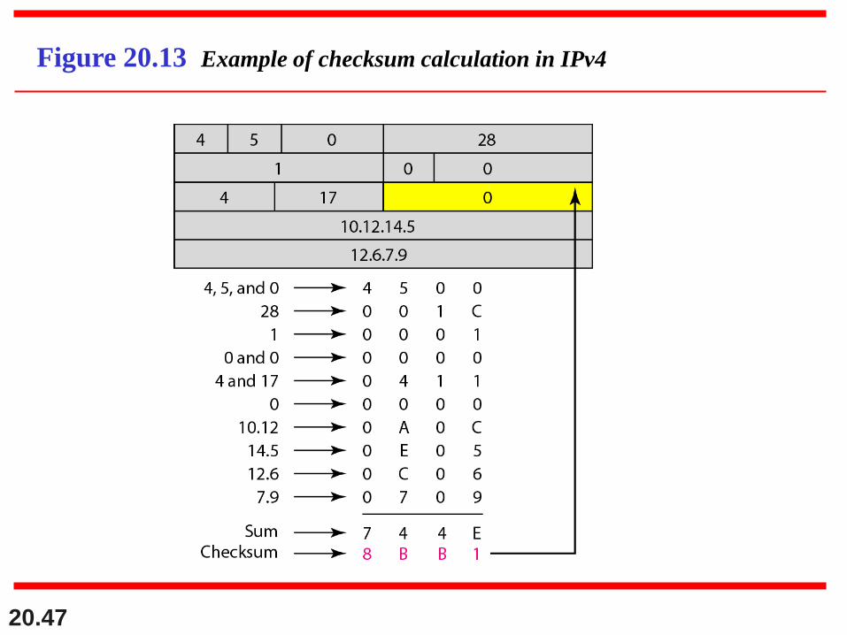
Figure 20.13 shows an example of a checksum
calculation for an IPv4 header without options. The
header is divided into 16-bit sections. All the sections are
added and the sum is complemented. The result is
inserted in the checksum field.
Example 20.10
20.47
Figure 20.13 Example of checksum calculation in IPv4
20.48
20-3 IPv6
The network layer protocol in the TCP/IP protocol
suite is currently IPv4. Although IPv4 is well designed,
data communication has evolved since the inception of
IPv4 in the 1970s. IPv4 has some deficiencies that
make it unsuitable for the fast-growing Internet.
Advantages
Packet Format
Extension Headers
Topics discussed in this section:
20.49
20-3 IPv6
Disadvantages of IPV4:
•Despite all short-term solutions, such as subnetting,
classless addressing, and NAT,
(address depletion).
•The Internet must accommodate real-time audio and
video transmission.
•The Internet must accommodate real-time encryption
and authentication of data for some applications.
20.50
20-3 IPv6
The format and the
length of the IP address
were changed along
with the packet format.
Related protocols, such
as ICMP,ARP, IGMP
and Routing Protocol.
20.51
20-3 IPv6 advantages over IPv4
1. Large address space.
2. Better Header format.
3. New options to add new functions,
4. IPv6 is designed to allow the extension of the
protocol if required by new technologies or
applications.
5. More Security.
6. Add a mechanism (called-jlow label) has been
added to enable the source to request special
handling of the packet. This mechanism can be
used to support traffic such as real-time audio
and video.
20.52
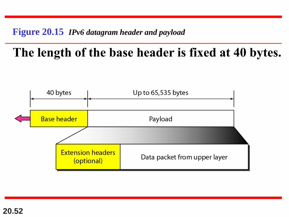
Figure 20.15 IPv6 datagram header and payload
The length of the base header is fixed at 40 bytes.
20.53
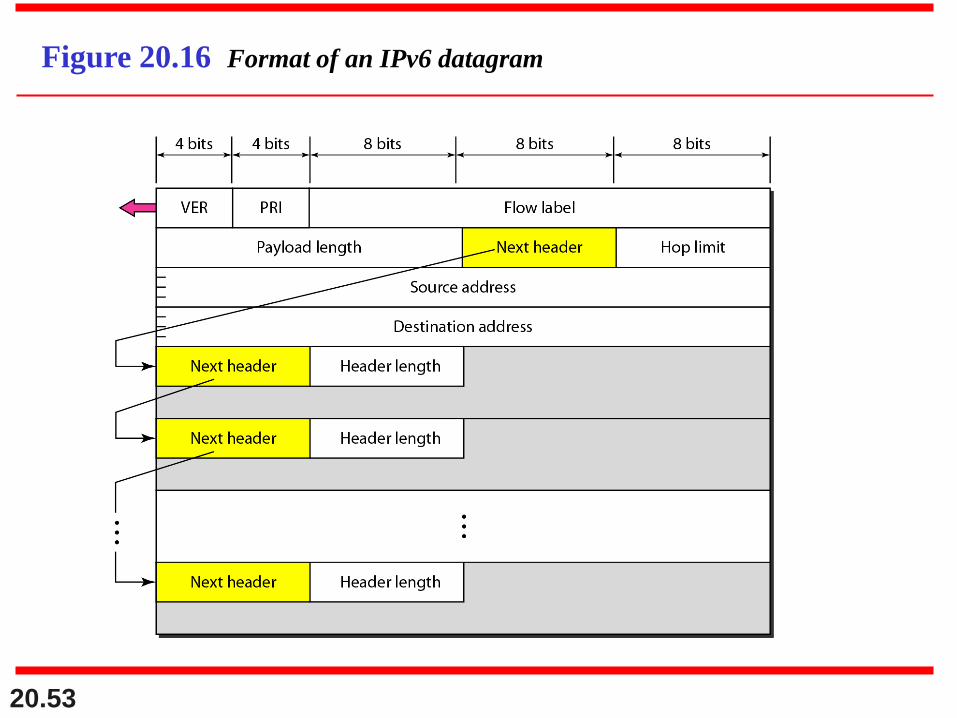
Figure 20.16 Format of an IPv6 datagram
20.54
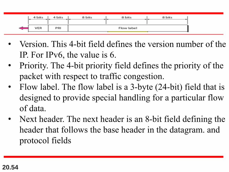
• Version. This 4-bit field defines the version number of the
IP. For IPv6, the value is 6.
• Priority. The 4-bit priority field defines the priority of the
packet with respect to traffic congestion.
• Flow label. The flow label is a 3-byte (24-bit) field that is
designed to provide special handling for a particular flow
of data.
• Next header. The next header is an 8-bit field defining the
header that follows the base header in the datagram. and
protocol fields
20.55
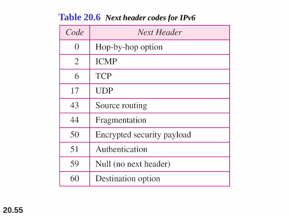
Table 20.6 Next header codes for IPv6
20.56
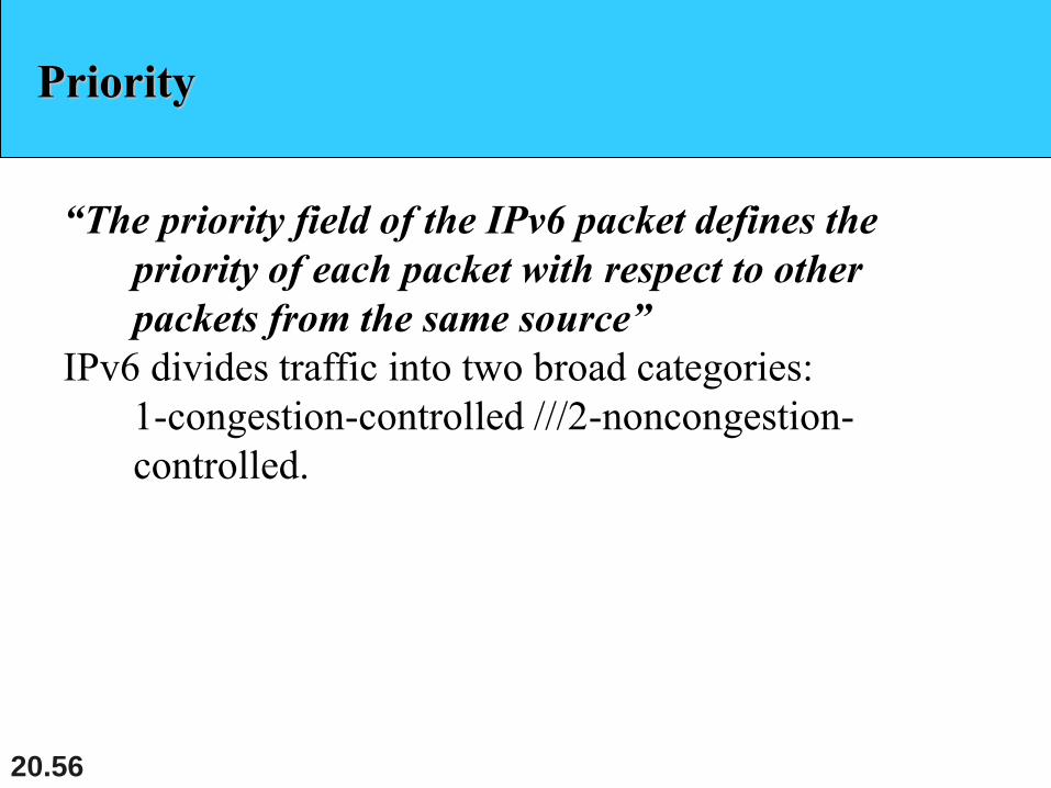
Priority
“The priority field of the IPv6 packet defines the
priority of each packet with respect to other
packets from the same source”
IPv6 divides traffic into two broad categories:
1-congestion-controlled ///2-noncongestion-
controlled.

20.57
Priority
•If a source adapts itself to traffic slowdown when there is
congestion, the traffic is referred to as congestion-
controlled traffic.
•Congestion-controlled data are assigned priorities from 0
to 7, as listed in
Table 20.7.
20.58
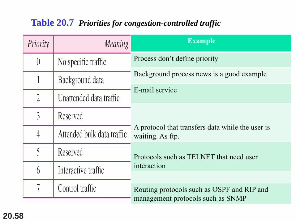
Table 20.7 Priorities for congestion-controlled traffic
Example
Process don’t define priority
Background process news is a good example
E-mail service
A protocol that transfers data while the user is
waiting. As ftp.
Protocols such as TELNET that need user
interaction
Routing protocols such as OSPF and RIP and
management protocols such as SNMP
20.59
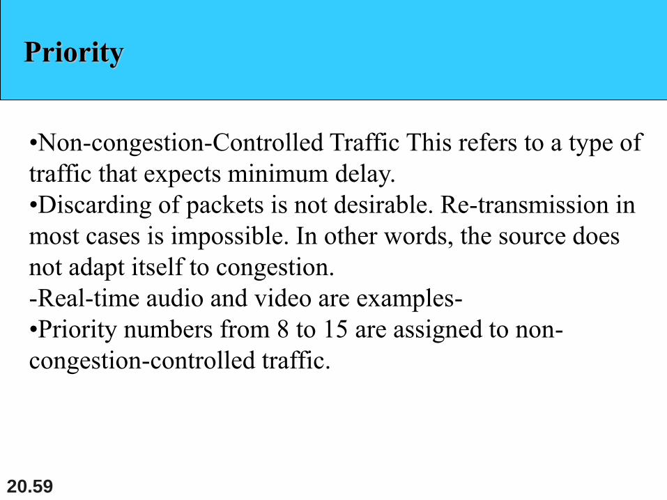
Priority
•Non-congestion-Controlled Traffic This refers to a type of
traffic that expects minimum delay.
•Discarding of packets is not desirable. Re-transmission in
most cases is impossible. In other words, the source does
not adapt itself to congestion.
-Real-time audio and video are examples-
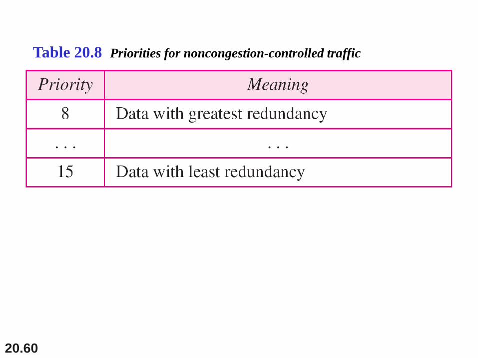
•Priority numbers from 8 to 15 are assigned to non-
congestion-controlled traffic.
20.60
Table 20.8 Priorities for noncongestion-controlled traffic
20.61
Flow Label 3-byte
• The combination of the source address and the value of
the flow label uniquely defines a flow of packets for
handling by routers
• Label on router, a flow is a sequence of packets that
share the same characteristics such as traveling the same
path.
• When the router receives a packet, it consults its flow
label table to find the corresponding entry for the flow
label value defined in the packet.
• This can be used in different application as speed up the
processing, Real-time audio or video
20.62
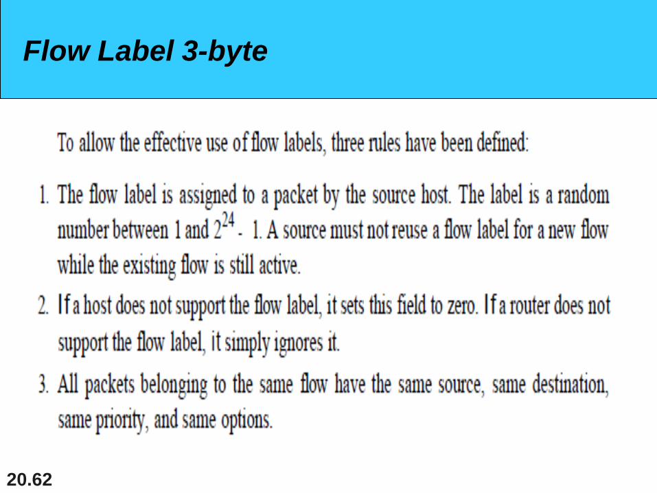
Flow Label 3-byte
20.63
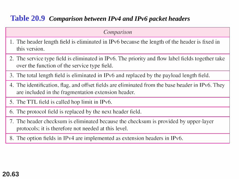
Table 20.9 Comparison between IPv4 and IPv6 packet headers
20.64
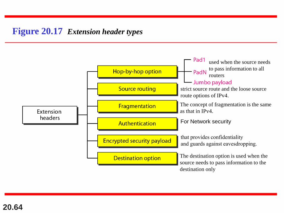
Figure 20.17 Extension header types
used when the source needs
to pass information to all
routers
strict source route and the loose source
route options of IPv4.
The concept of fragmentation is the same
as that in IPv4.
For Network security
that provides confidentiality
and guards against eavesdropping.
The destination option is used when the
source needs to pass information to the
destination only
20.65
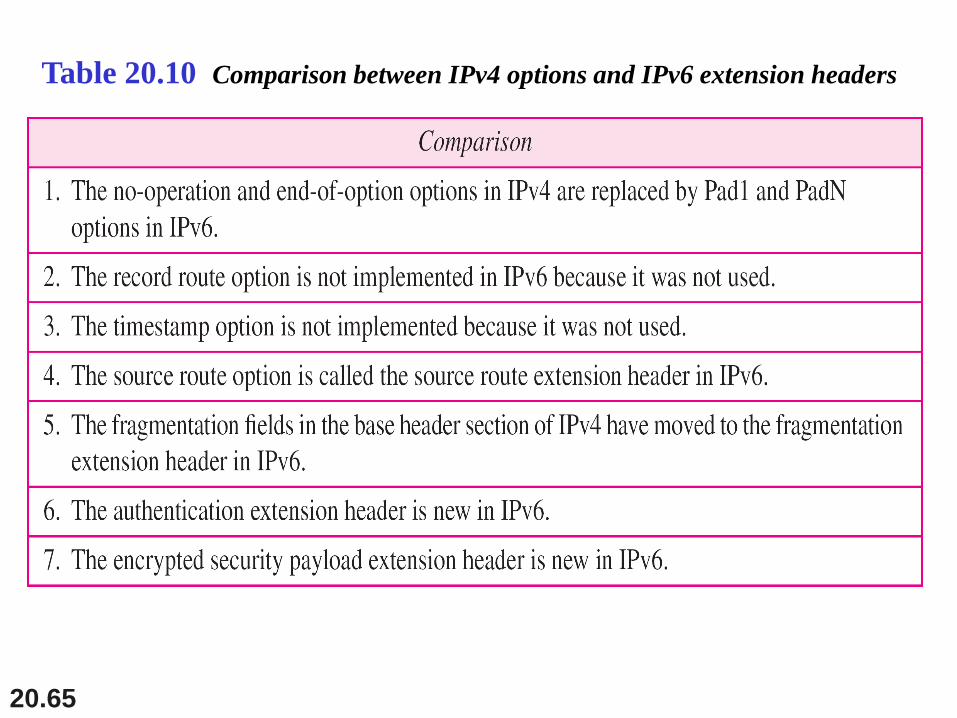
Table 20.10 Comparison between IPv4 options and IPv6 extension headers
20.66
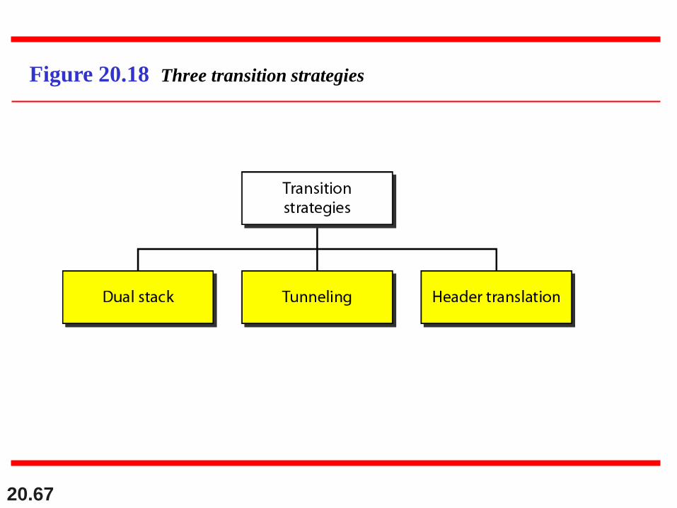
20-4 TRANSITION FROM IPv4 TO IPv6
Because of the huge number of systems on the
Internet, the transition from IPv4 to IPv6 cannot
happen suddenly. It takes a considerable amount of
time before every system in the Internet can move from
IPv4 to IPv6. The transition must be smooth to prevent
any problems between IPv4 and IPv6 systems.
Dual Stack
Tunneling
Header Translation
Topics discussed in this section:
20.67
Figure 20.18 Three transition strategies
20.68
Dual stack
• a station must run IPv4 and IPv6 simultaneously until all
the Internet uses IPv6.
• To determine which version to use when sending a
packet to a destination, the source host queries the DNS.
• If the DNS returns an IPv4 address, the source host
sends an IPv4 packet. If the DNS returns an IPv6
address, the source host sends an IPv6 packet.
20.69
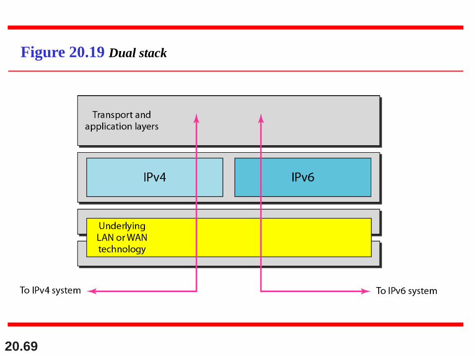
Figure 20.19 Dual stack
20.70
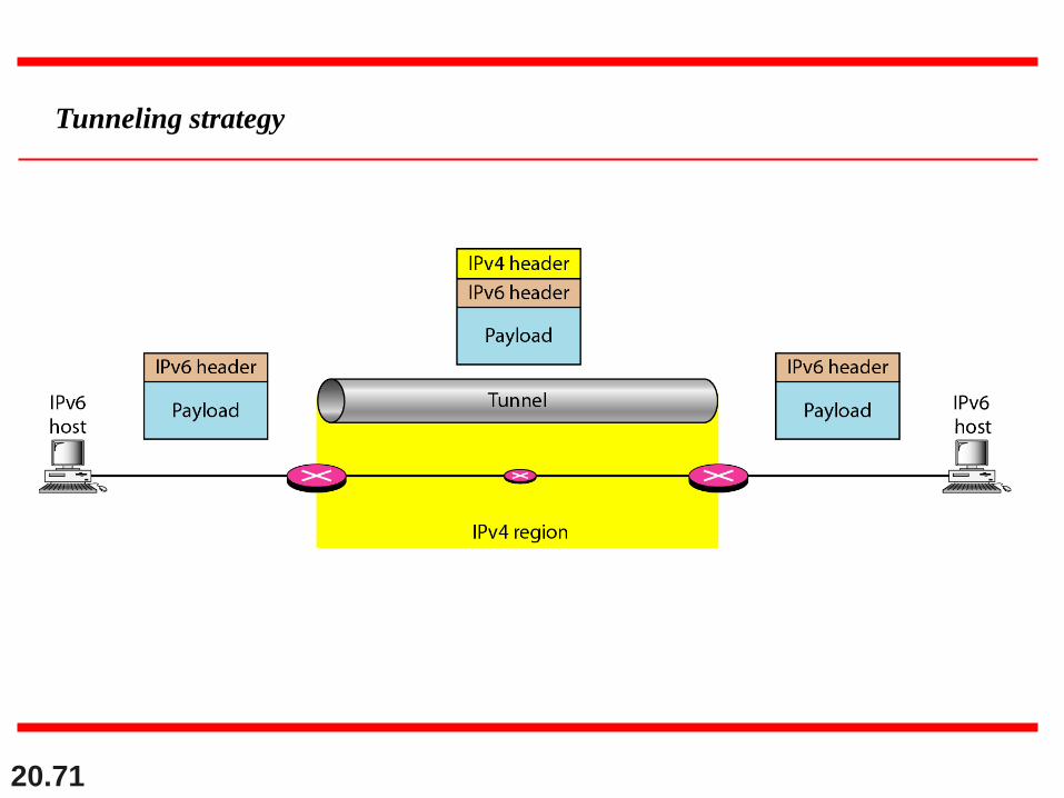
Tunneling strategy
• is a strategy used when two computers using IPv6 want
to communicate with each other and the packet must pass
through a region that uses IPv4.
• To pass through this region, the packet must have an IPv4
address. So the IPv6 packet is encapsulated in an IPv4.
• It seems as if the IPv6 packet goes through a tunnel at
one end and emerges at the other end. To make it clear
that the IPv4 packet is carrying an IPv6 packet as data,
the protocol value is set to 41.
20.71
Tunneling strategy
20.72
Header translation strategy
• Header translation is necessary when the majority of
the Internet has moved to IPv6 but some systems still
use IPv4.
• The sender wants to use IPv6, but the receiver does not
understand IPv6.
• Tunneling does not work in this situation because the
packet must be in the IPv4 format to be understood by
the receiver.
• In this case, the header format must be totally changed
through header translation.
20.73
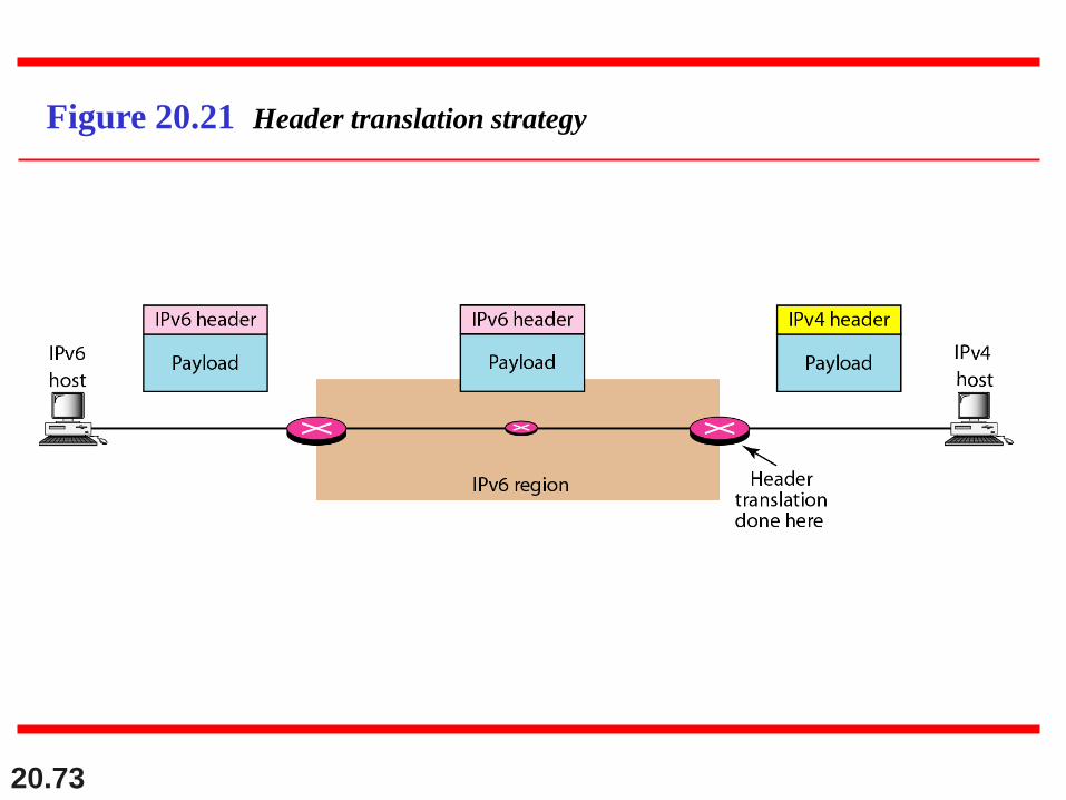
Figure 20.21 Header translation strategy
20.74
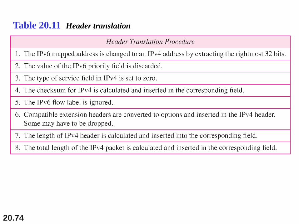
Table 20.11 Header translation