Embed Size (px)
Citation preview
Design of Machine Members-I Unit-1Lecture Notes – 1
Introduction
The subject Machine Design is the creation of new and better machines and improving the
existing ones. A new or better machine is one which is more economical in the overall cost of
production and operation. The process of design is a long and time consuming one. From the
study of existing ideas, a new idea has to be conceived. The idea is then studied keeping in
mind its commercial success and given shape and form in the form of drawings. In the
preparation of these drawings, care must be taken of the availability of resources in money, in
men and in materials required for the successful completion of the new idea into an actual
reality. In designing a machine component, it is necessary to have a good knowledge of many
subjects such as Mathematics, Engineering Mechanics, Strength of Materials, Theory of
Machines, Workshop Processes and Engineering Drawing.
Classifications of Machine Design
The machine design may be classified as follows:
1. Adaptive design. In most cases, the designer’s work is concerned with adaptation of
existing designs. This type of design needs no special knowledge or skill and can be
attempted by designers of ordinary technical training. The designer only makes minor
alternation or modification in the existing designs of the product.
2. Development design. This type of design needs considerable scientific training and design
ability in order to modify the existing designs into a new idea by adopting a new material or
different method of manufacture. In this case, though the designer starts from the existing
design, but the final product may differ quite markedly from the original product.
3. New design. This type of design needs lot of research, technical ability and creative
thinking. Only those designers who have personal qualities of a sufficiently high order can
take up the work of a new design. The designs, depending upon the methods used, may be
classified as follows:
(a) Rational design. This type of design depends upon mathematical formulae of principle of
mechanics.
(b) Empirical design. This type of design depends upon empirical formulae based on the
practice and past experience.
(c) Industrial design. This type of design depends upon the production aspects to
manufacture any machine component in the industry.
www.jntuworld.com || www.android.jntuworld.com || www.jwjobs.net || www.android.jwjobs.net
www.jntuworld.com || www.jwjobs.net
Design of Machine Members-I Unit-1Lecture Notes – 1
(d) Optimum design. It is the best design for the given objective function under the specified
constraints. It may be achieved by minimising the undesirable effects.
(e) System design. It is the design of any complex mechanical system like a motor car.
(f) Element design. It is the design of any element of the mechanical system like piston,
crankshaft, connecting rod, etc.
(g) Computer aided design. This type of design depends upon the use of computer systems to
assist in the creation, modification, analysis and optimisation of a design.
General Considerations in Machine Design
Following are the general considerations in designing a machine component:
1. Type of load and stresses caused by the load. The load, on a machine component, may act
in several ways due to which the internal stresses are set up. The various types of load and
stresses are discussed later.
2. Motion of the parts or kinematics of the machine. The successful operation of any
machine depends largely upon the simplest arrangement of the parts which will give the
motion required.
The motion of the parts may be:
(a) Rectilinear motion which includes unidirectional and reciprocating motions.
(b) Curvilinear motion which includes rotary, oscillatory and simple harmonic.
(c) Constant velocity.
(d) Constant or variable acceleration.
3. Selection of materials. It is essential that a designer should have a thorough knowledge of
the properties of the materials and their behaviour under working conditions. Some of the
important characteristics of materials are: strength, durability, flexibility, weight, resistance to
heat and corrosion, ability to cast, welded or hardened, machinability, electrical conductivity,
etc. The various types of engineering materials and their properties are discussed later.
4. Form and size of the parts. The form and size are based on judgment. The smallest
practicable cross-section may be used, but it may be checked that the stresses induced in the
designed cross-section are reasonably safe. In order to design any machine part for form and
www.jntuworld.com || www.android.jntuworld.com || www.jwjobs.net || www.android.jwjobs.net
www.jntuworld.com || www.jwjobs.net
Design of Machine Members-I Unit-1Lecture Notes – 1
size, it is necessary to know the forces which the part must sustain. It is also important to
anticipate any suddenly applied or impact load which may cause failure.
5. Frictional resistance and lubrication. There is always a loss of power due to frictional
resistance and it should be noted that the friction of starting is higher than that of running
friction. It is, therefore, essential that a careful attention must be given to the matter of
lubrication of all surfaces which move in contact with others, whether in rotating, sliding, or
rolling bearings.
6. Convenient and economical features. In designing, the operating features of the machine
should be carefully studied. The starting, controlling and stopping levers should be located on
the basis of convenient handling. The adjustment for wear must be provided employing the
various take up devices and arranging them so that the alignment of parts is preserved. If
parts are to be changed for different products or replaced on account of wear or breakage,
easy access should be provided and the necessity of removing other parts to accomplish this
should be avoided if possible. The economical operation of a machine which is to be used for
production or for the processing of material should be studied, in order to learn whether it has
the maximum capacity consistent with the production of good work.
7. Use of standard parts. The use of standard parts is closely related to cost, because the cost
of standard or stock parts is only a fraction of the cost of similar parts made to order. The
standard or stock parts should be used whenever possible; parts for which patterns are already
in existence such as gears, pulleys and bearings and parts which may be selected from regular
shop stock such as screws, nuts and pins. Bolts and studs should be as few as possible to
avoid the delay caused by changing drills, reamers and taps and also to decrease the number
of wrenches required.
8. Safety of operation. Some machines are dangerous to operate, especially those which are
speeded up to insure production at a maximum rate. Therefore, any moving part of a machine
which is within the zone of a worker is considered an accident hazard and may be the cause
of an injury. It is, therefore, necessary that a designer should always provide safety devices
for the safety of the operator. The safety appliances should in no way interfere with operation
of the machine.
www.jntuworld.com || www.android.jntuworld.com || www.jwjobs.net || www.android.jwjobs.net
www.jntuworld.com || www.jwjobs.net
Design of Machine Members-I Unit-1Lecture Notes – 1
9. Workshop facilities. A design engineer should be familiar with the limitations of this
employer’s workshop, in order to avoid the necessity of having work done in some other
workshop. It is sometimes necessary to plan and supervise the workshop operations and to
draft methods for casting, handling and machining special parts.
10. Number of machines to be manufactured. The number of articles or machines to be
manufactured affects the design in a number of ways. The engineering and shop costs which
are called fixed charges or overhead expenses are distributed over the number of articles to be
manufactured. If only a few articles are to be made, extra expenses are not justified unless the
machine is large or of some special design. An order calling for small number of the product
will not permit any undue expense in the workshop processes, so that the designer should
restrict his specification to standard parts as much as possible.
11. Cost of construction. The cost of construction of an article is the most important
consideration involved in design. In some cases, it is quite possible that the high cost of an
article may immediately bar it from further considerations. If an article has been invented and
tests of handmade samples have shown that it has commercial value, it is then possible to
justify the expenditure of a considerable sum of money in the design and development of
automatic machines to produce the article, especially if it can be sold in large numbers. The
aim of design engineer under all conditions should be to reduce the manufacturing cost to the
minimum.
12. Assembling. Every machine or structure must be assembled as a unit before it can
function. Large units must often be assembled in the shop, tested and then taken to be
transported to their place of service. The final location of any machine is important and the
design engineer must anticipate the exact location and the local facilities for erection.
General Procedure in Machine Design
In designing a machine component, there is no rigid rule. The problem may be attempted in
several ways. However, the general procedure to solve a design problem is as follows:
www.jntuworld.com || www.android.jntuworld.com || www.jwjobs.net || www.android.jwjobs.net
www.jntuworld.com || www.jwjobs.net
Design of Machine Members-I
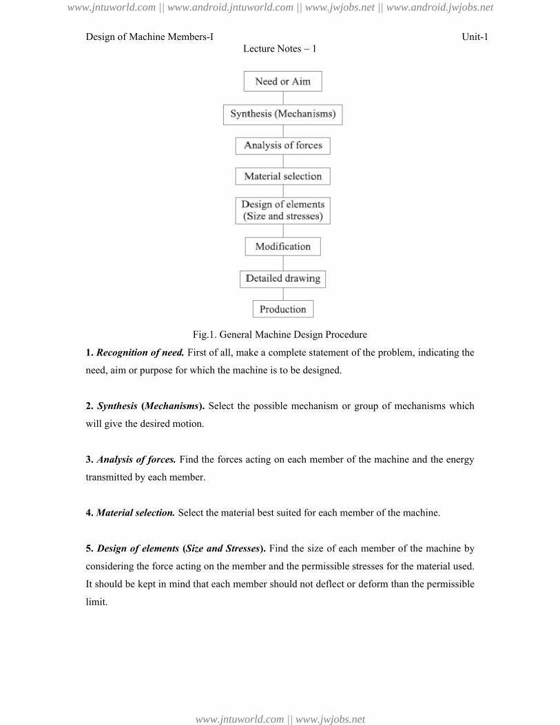
Fig.1. General Machine Design Procedure
1. Recognition of need. First of all, make a complete statement of the problem, indicating the
need, aim or purpose for which the machine is to be designed.
2. Synthesis (Mechanisms). Select the
will give the desired motion.
3. Analysis of forces. Find the forces acting on each member of the machine and the energy
transmitted by each member.
4. Material selection. Select the material best suited fo
5. Design of elements (Size and Stresses
considering the force acting on the member and the permissible stresses for the material used.
It should be kept in mind that each memb
limit.
Lecture Notes – 1
Fig.1. General Machine Design Procedure
First of all, make a complete statement of the problem, indicating the
need, aim or purpose for which the machine is to be designed.
Select the possible mechanism or group of mechanisms which
Find the forces acting on each member of the machine and the energy
Select the material best suited for each member of the machine.
Size and Stresses). Find the size of each member of the machine by
considering the force acting on the member and the permissible stresses for the material used.
It should be kept in mind that each member should not deflect or deform than the permissible
Unit-1
First of all, make a complete statement of the problem, indicating the
possible mechanism or group of mechanisms which
Find the forces acting on each member of the machine and the energy
r each member of the machine.
Find the size of each member of the machine by
considering the force acting on the member and the permissible stresses for the material used.
er should not deflect or deform than the permissible
www.jntuworld.com || www.android.jntuworld.com || www.jwjobs.net || www.android.jwjobs.net
www.jntuworld.com || www.jwjobs.net
Design of Machine Members-I Unit-1Lecture Notes – 1
6. Modification. Modify the size of the member to agree with the past experience and
judgment to facilitate manufacture. The modification may also be necessary by consideration
of manufacturing to reduce overall cost.
7. Detailed drawing. Draw the detailed drawing of each component and the assembly of the
machine with complete specification for the manufacturing processes suggested.
8. Production. The component, as per the drawing, is manufactured in the workshop.
The flow chart for the general procedure in machine design is shown in Fig.
Note: When there are number of components in the market having the same qualities of
efficiency, durability and cost, then the customer will naturally attract towards the most
appealing product. The aesthetic and ergonomics are very important features which gives
grace and lustre to product and dominates the market.
Engineering materials and their properties
The knowledge of materials and their properties is of great significance for a design engineer.
The machine elements should be made of such a material which has properties suitable for
the conditions of operation. In addition to this, a design engineer must be familiar with the
effects which the manufacturing processes and heat treatment have on the properties of the
materials. Now, we shall discuss the commonly used engineering materials and their
properties in Machine Design.
Classification of Engineering Materials
The engineering materials are mainly classified as:
1. Metals and their alloys, such as iron, steel, copper, aluminum, etc.
2. Non-metals, such as glass, rubber, plastic, etc.
The metals may be further classified as:
(a) Ferrous metals and (b) Non-ferrous metals.
The *ferrous metals are those which have the iron as their main constituent, such as cast iron,
wrought iron and steel.
www.jntuworld.com || www.android.jntuworld.com || www.jwjobs.net || www.android.jwjobs.net
www.jntuworld.com || www.jwjobs.net
Design of Machine Members-I Unit-1Lecture Notes – 1
The non-ferrous metals are those which have a metal other than iron as their main
constituent, such as copper, aluminum, brass, tin, zinc, etc.
Selection of Materials for Engineering Purposes
The selection of a proper material, for engineering purposes, is one of the most difficult
problems for the designer. The best material is one which serves the desired objective at the
minimum cost. The following factors should be considered while selecting the material:
1. Availability of the materials,
2. Suitability of the materials for the working conditions in service, and
3. The cost of the materials.
The important properties, which determine the utility of the material, are physical, chemical
and mechanical properties. We shall now discuss the physical and mechanical properties of
the material in the following articles.
Physical Properties of Metals
The physical properties of the metals include luster, colour, size and shape, density, electric
and thermal conductivity, and melting point. The following table shows the important
physical properties of some pure metals.
Mechanical Properties of Metals
The mechanical properties of the metals are those which are associated with the ability of the
material to resist mechanical forces and load. These mechanical properties of the metal
include strength, stiffness, elasticity, plasticity, ductility, brittleness, malleability, toughness,
resilience, creep and hardness. We shall now discuss these properties as follows:
1. Strength. It is the ability of a material to resist the externally applied forces without
breaking or yielding. The internal resistance offered by a part to an externally applied force is
called stress.
2. Stiffness. It is the ability of a material to resist deformation under stress. The modulus of
elasticity is the measure of stiffness.
www.jntuworld.com || www.android.jntuworld.com || www.jwjobs.net || www.android.jwjobs.net
www.jntuworld.com || www.jwjobs.net
Design of Machine Members-I Unit-1Lecture Notes – 1
3. Elasticity. It is the property of a material to regain its original shape after deformation
when the external forces are removed. This property is desirable for materials used in tools
and machines. It may be noted that steel is more elastic than rubber.
4. Plasticity. It is property of a material which retains the deformation produced under load
permanently. This property of the material is necessary for forgings, in stamping images on
coins and in ornamental work.
5. Ductility. It is the property of a material enabling it to be drawn into wire with the
application of a tensile force. A ductile material must be both strong and plastic. The ductility
is usually measured by the terms, percentage elongation and percentage reduction in area.
The ductile material commonly used in engineering practice (in order of diminishing
ductility) are mild steel, copper, aluminium, nickel, zinc, tin and lead.
6. Brittleness. It is the property of a material opposite to ductility. It is the property of
breaking of a material with little permanent distortion. Brittle materials when subjected to
tensile loads snap off without giving any sensible elongation. Cast iron is a brittle material.
7. Malleability. It is a special case of ductility which permits materials to be rolled or
hammered into thin sheets. A malleable material should be plastic but it is not essential to be
so strong. The malleable materials commonly used in engineering practice (in order of
diminishing malleability) are lead, soft steel, wrought iron, copper and aluminium.
8. Toughness. It is the property of a material to resist fracture due to high impact loads like
hammer blows. The toughness of the material decreases when it is heated. It is measured by
the amount of energy that a unit volume of the material has absorbed after being stressed upto
the point of fracture. This property is desirable in parts subjected to shock and impact loads.
9. Machinability. It is the property of a material which refers to a relative case with which a
material can be cut. The machinability of a material can be measured in a number of ways
such as comparing the tool life for cutting different materials or thrust required to remove the
material at some given rate or the energy required to remove a unit volume of the material. It
may be noted that brass can be easily machined than steel.
www.jntuworld.com || www.android.jntuworld.com || www.jwjobs.net || www.android.jwjobs.net
www.jntuworld.com || www.jwjobs.net
Design of Machine Members-I Unit-1Lecture Notes – 1
10. Resilience. It is the property of a material to absorb energy and to resist shock and impact
loads. It is measured by the amount of energy absorbed per unit volume within elastic limit.
This property is essential for spring materials.
11. Creep. When a part is subjected to a constant stress at high temperature for a long period
of time, it will undergo a slow and permanent deformation called creep. This property is
considered in designing internal combustion engines, boilers and turbines.
12. Fatigue. When a material is subjected to repeated stresses, it fails at stresses below the
yield point stresses. Such type of failure of a material is known as *fatigue. The failure is
caused by means of a progressive crack formation which are usually fine and of microscopic
size. This property is considered in designing shafts, connecting rods, springs, gears, etc.
13. Hardness. It is a very important property of the metals and has a wide variety of
meanings. It embraces many different properties such as resistance to wear, scratching,
deformation and machinability etc. It also means the ability of a metal to cut another metal.
The hardness is usually expressed in numbers which are dependent on the method of making
the test. The hardness of a metal may be determined by the following tests:
(a) Brinell hardness test,
(b) Rockwell hardness test,
(c) Vickers hardness (also called Diamond Pyramid) test, and
(d) Shore scleroscope.
Steel
It is an alloy of iron and carbon, with carbon content up to a maximum of 1.5%. The carbon
occurs in the form of iron carbide, because of its ability to increase the hardness and strength
of the steel. Other elements e.g. silicon, sulphur, phosphorus and manganese are also present
to greater or lesser amount to impart certain desired properties to it. Most of the steel
produced now-a-days is plain carbon steel or simply carbon steel. A carbon steel is defined
as a steel which has its properties mainly due to its carbon content and does not contain more
than 0.5% of silicon and 1.5% of manganese.
The plain carbon steels varying from 0.06% carbon to 1.5% carbon are divided into the
following types depending upon the carbon content.
1. Dead mild steel — up to 0.15% carbon
www.jntuworld.com || www.android.jntuworld.com || www.jwjobs.net || www.android.jwjobs.net
www.jntuworld.com || www.jwjobs.net
Design of Machine Members-I Unit-1Lecture Notes – 1
2. Low carbon or mild steel — 0.15% to 0.45% carbon
3. Medium carbon steel — 0.45% to 0.8% carbon
4. High carbon steel — 0.8% to 1.5% carbon
According to Indian standard *[IS: 1762 (Part-I)–1974], a new system of designating the steel
is recommended. According to this standard, steels are designated on the following two basis:
(a) On the basis of mechanical properties, and (b) On the basis of chemical composition. We
shall now discuss, in detail, the designation of steel on the above two basis, in the following
pages.
Steels Designated on the Basis of Mechanical Properties
These steels are carbon and low alloy steels where the main criterion in the selection and
inspection of steel is the tensile strength or yield stress. According to Indian standard IS:
1570 (Part–I)- 1978 (Reaffirmed 1993), these steels are designated by a symbol ‘Fe’ or ‘Fe E’
depending on whether the steel has been specified on the basis of minimum tensile strength
or yield strength, followed by the figure indicating the minimum tensile strength or yield
stress in N/mm2. For example ‘Fe 290’ means a steel having minimum tensile strength of 290
N/mm2 and ‘Fe E 220’ means a steel having yield strength of 220 N/mm2.
Steels Designated on the Basis of Chemical Composition
According to Indian standard, IS : 1570 (Part II/Sec I)-1979 (Reaffirmed 1991), the carbon
steels are designated in the following order :
(a) Figure indicating 100 times the average percentage of carbon content,
(b) Letter ‘C’, and
(c) Figure indicating 10 times the average percentage of manganese content. The figure after
multiplying shall be rounded off to the nearest integer.
For example 20C8 means a carbon steel containing 0.15 to 0.25 per cent (0.2 per cent on
average) carbon and 0.60 to 0.90 per cent (0.75 per cent rounded off to 0.8 per cent on an
average) manganese.
Effect of Impurities on Steel
The following are the effects of impurities like silicon, sulphur, manganese and phosphorus
on steel.
www.jntuworld.com || www.android.jntuworld.com || www.jwjobs.net || www.android.jwjobs.net
www.jntuworld.com || www.jwjobs.net
Design of Machine Members-I Unit-1Lecture Notes – 1
1. Silicon. The amount of silicon in the finished steel usually ranges from 0.05 to 0.30%.
Silicon is added in low carbon steels to prevent them from becoming porous. It removes the
gases and oxides, prevent blow holes and thereby makes the steel tougher and harder.
2. Sulphur. It occurs in steel either as iron sulphide or manganese sulphide. Iron sulphide
because of its low melting point produces red shortness, whereas manganese sulphide does
not affect so much. Therefore, manganese sulphide is less objectionable in steel than iron
sulphide.
3. Manganese. It serves as a valuable deoxidising and purifying agent in steel. Manganese
also combines with sulphur and thereby decreases the harmful effect of this element
remaining in the steel. When used in ordinary low carbon steels, manganese makes the metal
ductile and of good bending qualities. In high speed steels, it is used to toughen the metal and
to increase its critical temperature.
4. Phosphorus. It makes the steel brittle. It also produces cold shortness in steel. In low
carbon steels, it raises the yield point and improves the resistance to atmospheric corrosion.
The sum of carbon and phosphorus usually does not exceed 0.25%.
References:
1. Machine Design - V.Bandari .
2. Machine Design – R.S. Khurmi
3. Design Data hand Book - S MD Jalaludin.
www.jntuworld.com || www.android.jntuworld.com || www.jwjobs.net || www.android.jwjobs.net
www.jntuworld.com || www.jwjobs.net
Design of Machine Members-I Unit-1Lecture Notes - 2
Manufacturing considerations in Machine design
Manufacturing Processes
The knowledge of manufacturing processes is of great importance for a design engineer. The
following are the various manufacturing processes used in Mechanical Engineering.
1. Primary shaping processes. The processes used for the preliminary shaping of the
machine component are known as primary shaping processes. The common operations used
for this process are casting, forging, extruding, rolling, drawing, bending, shearing, spinning,
powder metal forming, squeezing, etc.
2. Machining processes. The processes used for giving final shape to the machine
component, according to planned dimensions are known as machining processes. The
common operations used for this process are turning, planning, shaping, drilling, boring,
reaming, sawing, broaching, milling, grinding, hobbing, etc.
3. Surface finishing processes. The processes used to provide a good surface finish for the
machine component are known as surface finishing processes. The common operations used
for this process are polishing, buffing, honing, lapping, abrasive belt grinding, barrel
tumbling, electroplating, super finishing, sheradizing, etc.
4. Joining processes. The processes used for joining machine components are known as
joining processes. The common operations used for this process are welding, riveting,
soldering, brazing, screw fastening, pressing, sintering, etc.
5. Processes effecting change in properties. These processes are used to impart certain
specific properties to the machine components so as to make them suitable for particular
operations or uses. Such processes are heat treatment, hot-working, cold-working and shot
peening.
Other considerations in Machine design
1. Workshop facilities.
2. Number of machines to be manufactured
3. Cost of construction
www.jntuworld.com || www.android.jntuworld.com || www.jwjobs.net || www.android.jwjobs.net
www.jntuworld.com || www.jwjobs.net
Design of Machine Members-I
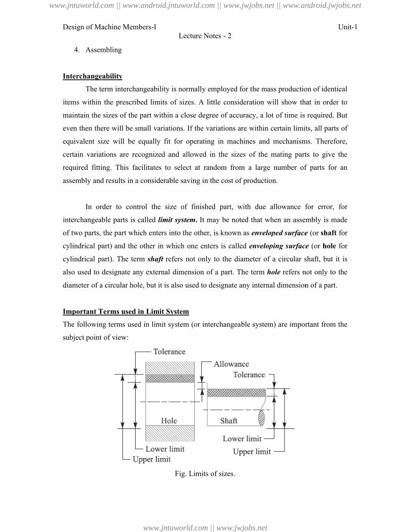
4. Assembling
Interchangeability
The term interchangeability is normally employed for the mass production of identical
items within the prescribed limits of sizes. A little consideration will show that in order to
maintain the sizes of the part within a close degree of accuracy, a lot of time is required. But
even then there will be small variations. If the variations are within certain limits, all parts of
equivalent size will be equally fit for operating in machines
certain variations are recognized and allowed in the sizes of the mating parts to give the
required fitting. This facilitates to select at random from a large number of parts for an
assembly and results in a considerable saving i
In order to control the size of finished part, with due allowance for error, for
interchangeable parts is called limit system
of two parts, the part which enters into the other, is known as
cylindrical part) and the other in which one enters is called
cylindrical part). The term shaft
also used to designate any external dimension of a part. The term
diameter of a circular hole, but it is also used to designate any internal dimension
Important Terms used in Limit System
The following terms used in limit system (or interchangeable system) are important from the
subject point of view:
Lecture Notes - 2
The term interchangeability is normally employed for the mass production of identical
items within the prescribed limits of sizes. A little consideration will show that in order to
ntain the sizes of the part within a close degree of accuracy, a lot of time is required. But
even then there will be small variations. If the variations are within certain limits, all parts of
equivalent size will be equally fit for operating in machines and mechanisms. Therefore,
certain variations are recognized and allowed in the sizes of the mating parts to give the
required fitting. This facilitates to select at random from a large number of parts for an
assembly and results in a considerable saving in the cost of production.
In order to control the size of finished part, with due allowance for error, for
limit system. It may be noted that when an assembly is made
of two parts, the part which enters into the other, is known as enveloped surface
cylindrical part) and the other in which one enters is called enveloping surface
shaft refers not only to the diameter of a circular shaft, but it is
also used to designate any external dimension of a part. The term hole refers not only to the
diameter of a circular hole, but it is also used to designate any internal dimension
Important Terms used in Limit System
The following terms used in limit system (or interchangeable system) are important from the
Fig. Limits of sizes.
Unit-1
The term interchangeability is normally employed for the mass production of identical
items within the prescribed limits of sizes. A little consideration will show that in order to
ntain the sizes of the part within a close degree of accuracy, a lot of time is required. But
even then there will be small variations. If the variations are within certain limits, all parts of
and mechanisms. Therefore,
certain variations are recognized and allowed in the sizes of the mating parts to give the
required fitting. This facilitates to select at random from a large number of parts for an
In order to control the size of finished part, with due allowance for error, for
It may be noted that when an assembly is made
enveloped surface (or shaft for
enveloping surface (or hole for
refers not only to the diameter of a circular shaft, but it is
refers not only to the
diameter of a circular hole, but it is also used to designate any internal dimension of a part.
The following terms used in limit system (or interchangeable system) are important from the
www.jntuworld.com || www.android.jntuworld.com || www.jwjobs.net || www.android.jwjobs.net
www.jntuworld.com || www.jwjobs.net
Design of Machine Members-I
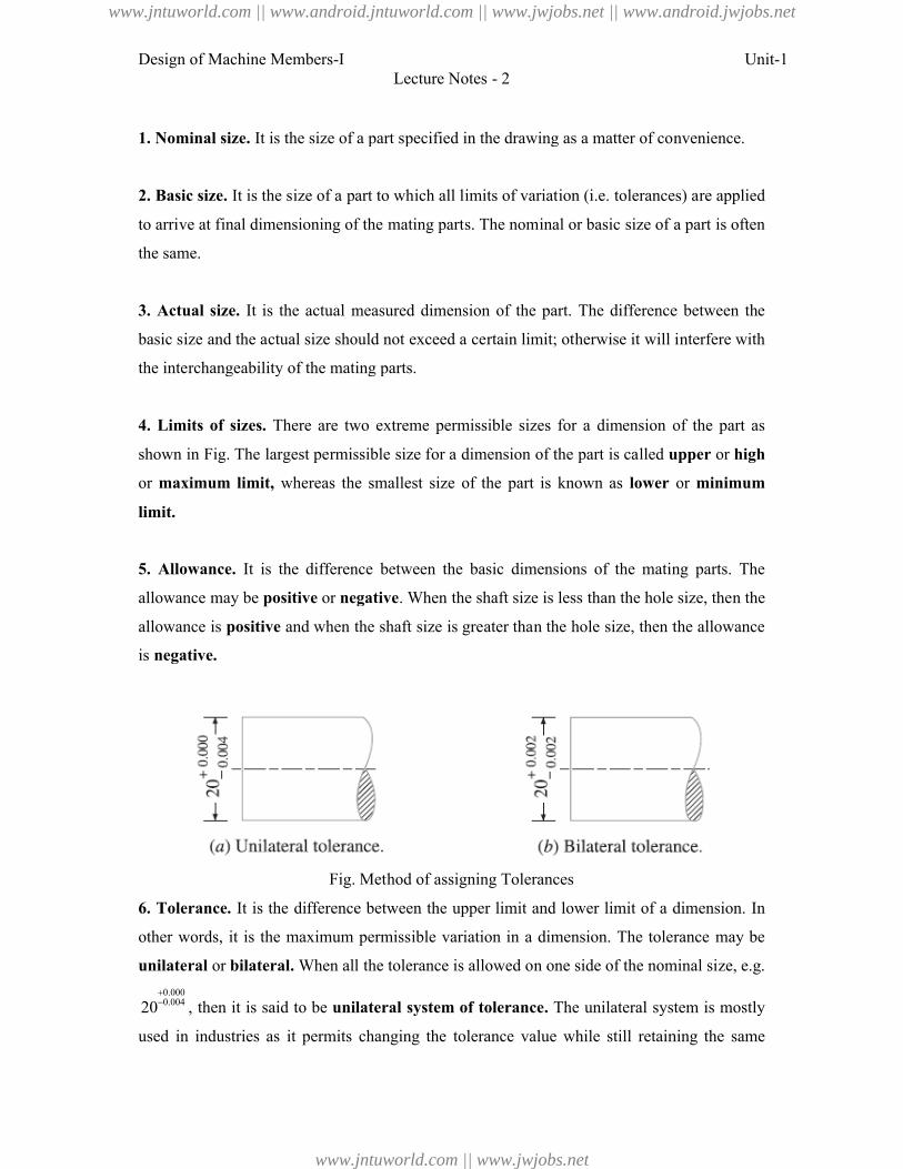
1. Nominal size. It is the size of a part specified in the drawing
2. Basic size. It is the size of a part to which all limits of variation (
to arrive at final dimensioning of the mating parts. The nominal or basic size of a part is often
the same.
3. Actual size. It is the actual measured dimension of the part. The difference between the
basic size and the actual size should not exceed a certain limit; otherwise it will interfere with
the interchangeability of the mating parts.
4. Limits of sizes. There are two e
shown in Fig. The largest permissible size for a dimension of the part is called
or maximum limit, whereas the smallest size of the part is known as
limit.
5. Allowance. It is the difference between the basic dimensions of the mating parts. The
allowance may be positive or negative
allowance is positive and when the shaft size is greater than the hole size, then t
is negative.
Fig. Method of assigning Tolerances
6. Tolerance. It is the difference between the upper limit and lower limit of a dimension. In
other words, it is the maximum permissible variation in a dimension. The tolerance may be
unilateral or bilateral. When all the tolerance is allowed on one side of the nominal size,
0.0000.00420 , then it is said to be unilateral system of tolerance
used in industries as it permits changing the tolerance value while still retaining the same
Lecture Notes - 2
It is the size of a part specified in the drawing as a matter of convenience.
It is the size of a part to which all limits of variation (i.e. tolerances) are applied
to arrive at final dimensioning of the mating parts. The nominal or basic size of a part is often
It is the actual measured dimension of the part. The difference between the
basic size and the actual size should not exceed a certain limit; otherwise it will interfere with
the interchangeability of the mating parts.
There are two extreme permissible sizes for a dimension of the part as
shown in Fig. The largest permissible size for a dimension of the part is called upper
whereas the smallest size of the part is known as lower
It is the difference between the basic dimensions of the mating parts. The
negative. When the shaft size is less than the hole size, then the
and when the shaft size is greater than the hole size, then t
Fig. Method of assigning Tolerances
It is the difference between the upper limit and lower limit of a dimension. In
other words, it is the maximum permissible variation in a dimension. The tolerance may be
When all the tolerance is allowed on one side of the nominal size,
unilateral system of tolerance. The unilateral system is mostly
used in industries as it permits changing the tolerance value while still retaining the same
Unit-1
as a matter of convenience.
. tolerances) are applied
to arrive at final dimensioning of the mating parts. The nominal or basic size of a part is often
It is the actual measured dimension of the part. The difference between the
basic size and the actual size should not exceed a certain limit; otherwise it will interfere with
xtreme permissible sizes for a dimension of the part as
upper or high
lower or minimum
It is the difference between the basic dimensions of the mating parts. The
. When the shaft size is less than the hole size, then the
and when the shaft size is greater than the hole size, then the allowance
It is the difference between the upper limit and lower limit of a dimension. In
other words, it is the maximum permissible variation in a dimension. The tolerance may be
When all the tolerance is allowed on one side of the nominal size, e.g.
The unilateral system is mostly
used in industries as it permits changing the tolerance value while still retaining the same
www.jntuworld.com || www.android.jntuworld.com || www.jwjobs.net || www.android.jwjobs.net
www.jntuworld.com || www.jwjobs.net
Design of Machine Members-I
allowance or type of fit. When the tolerance is allowed on both sides of the nominal size,
0.0020.00220 , then it is said to be bilateral system of tolerance
limit and – 0.002 is the lower limit.
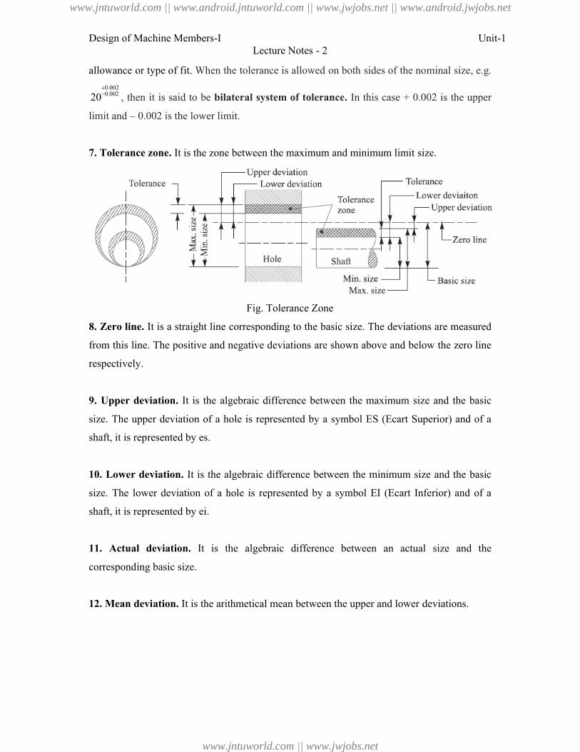
7. Tolerance zone. It is the zone between the maximum and minimum limit size.
8. Zero line. It is a straight line
from this line. The positive and negative deviations are shown above and below the zero line
respectively.
9. Upper deviation. It is the algebraic difference between the maximum size and the basic
size. The upper deviation of a hole is represented by a symbol
shaft, it is represented by es.
10. Lower deviation. It is the algebraic difference between t
size. The lower deviation of a hole is represented by a symbol
shaft, it is represented by ei.
11. Actual deviation. It is the algebraic difference between an actual size and the
corresponding basic size.
12. Mean deviation. It is the arithmetical mean between the upper and lower deviations.
Lecture Notes - 2
When the tolerance is allowed on both sides of the nominal size,
bilateral system of tolerance. In this case + 0.002 is the upper
0.002 is the lower limit.
It is the zone between the maximum and minimum limit size.
Fig. Tolerance Zone
It is a straight line corresponding to the basic size. The deviations are measured
from this line. The positive and negative deviations are shown above and below the zero line
It is the algebraic difference between the maximum size and the basic
size. The upper deviation of a hole is represented by a symbol ES (Ecart Superior) and of a
It is the algebraic difference between the minimum size and the basic
size. The lower deviation of a hole is represented by a symbol EI (Ecart Inferior) and of a
It is the algebraic difference between an actual size and the
It is the arithmetical mean between the upper and lower deviations.
Unit-1
When the tolerance is allowed on both sides of the nominal size, e.g.
In this case + 0.002 is the upper
It is the zone between the maximum and minimum limit size.
corresponding to the basic size. The deviations are measured
from this line. The positive and negative deviations are shown above and below the zero line
It is the algebraic difference between the maximum size and the basic
(Ecart Superior) and of a
he minimum size and the basic
(Ecart Inferior) and of a
It is the algebraic difference between an actual size and the
It is the arithmetical mean between the upper and lower deviations.
www.jntuworld.com || www.android.jntuworld.com || www.jwjobs.net || www.android.jwjobs.net
www.jntuworld.com || www.jwjobs.net
Design of Machine Members-I
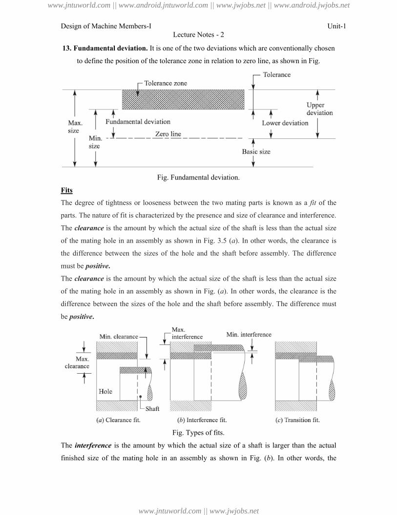
13. Fundamental deviation. It is one of the two deviations which are conventionally chosen
to define the position of the tolerance zone in relation to zero l
Fits
The degree of tightness or looseness between the two mating parts is known as a
parts. The nature of fit is characterized by the presence and size of clearance and interference.
The clearance is the amount by which the actual size of the shaft is less than the actual size
of the mating hole in an assembly as shown in Fig. 3.5 (
the difference between the sizes of the hole and the shaft before assemb
must be positive.
The clearance is the amount by which the actual size of the shaft is less than the actual size
of the mating hole in an assembly as shown in Fig. (
difference between the sizes of the hole and the shaft before assembly. The difference must
be positive.
The interference is the amount by which the actual size of a shaft is larger than the actual
finished size of the mating hole in an assembly as shown in Fig. (
Lecture Notes - 2
It is one of the two deviations which are conventionally chosen
to define the position of the tolerance zone in relation to zero line, as shown in Fig.
Fig. Fundamental deviation.
The degree of tightness or looseness between the two mating parts is known as a
parts. The nature of fit is characterized by the presence and size of clearance and interference.
is the amount by which the actual size of the shaft is less than the actual size
of the mating hole in an assembly as shown in Fig. 3.5 (a). In other words, the clearance is
the difference between the sizes of the hole and the shaft before assembly. The difference
is the amount by which the actual size of the shaft is less than the actual size
of the mating hole in an assembly as shown in Fig. (a). In other words, the clearance is the
the hole and the shaft before assembly. The difference must
Fig. Types of fits.
is the amount by which the actual size of a shaft is larger than the actual
finished size of the mating hole in an assembly as shown in Fig. (b). In other words, the
Unit-1
It is one of the two deviations which are conventionally chosen
ine, as shown in Fig.
The degree of tightness or looseness between the two mating parts is known as a fit of the
parts. The nature of fit is characterized by the presence and size of clearance and interference.
is the amount by which the actual size of the shaft is less than the actual size
). In other words, the clearance is
ly. The difference
is the amount by which the actual size of the shaft is less than the actual size
). In other words, the clearance is the
the hole and the shaft before assembly. The difference must
is the amount by which the actual size of a shaft is larger than the actual
). In other words, the
www.jntuworld.com || www.android.jntuworld.com || www.jwjobs.net || www.android.jwjobs.net
www.jntuworld.com || www.jwjobs.net
Design of Machine Members-I Unit-1Lecture Notes - 2
interference is the arithmetical difference between the sizes of the hole and the shaft, before
assembly. The difference must be negative.
Types of Fits
According to Indian standards, the fits are classified into the following three groups:
1. Clearance fit. In this type of fit, the size limits for mating parts are so selected that
clearance between them always occur, as shown in Fig. (a). It may be noted that in a
clearance fit, the tolerance zone of the hole is entirely above the tolerance zone of the shaft.
In a clearance fit, the difference between the minimum size of the hole and the maximum size
of the shaft is known as minimum clearance whereas the difference between the maximum
size of the hole and minimum size of the shaft is called maximum clearance as shown in Fig.
(a). The clearance fits may be slide fit, easy sliding fit, running fit, slack running fit and loose
running fit.
2. Interference fit. In this type of fit, the size limits for the mating parts are so selected that
interference between them always occur, as shown in Fig. (b). It may be noted that in an
interference fit, the tolerance zone of the hole is entirely below the tolerance zone of the
shaft. In an interference fit, the difference between the maximum size of the hole and the
minimum size of the shaft is known as minimum interference, whereas the difference
between the minimum size of the hole and the maximum size of the shaft is called maximum
interference, as shown in Fig. (b).
The interference fits may be shrink fit, heavy drive fit and light drive fit.
3. Transition fit. In this type of fit, the size limits for the mating parts are so selected that
either a clearance or interference may occur depending upon the actual size of the mating
parts, as shown in Fig. (c). It may be noted that in a transition fit, the tolerance zones of hole
and shaft overlap. The transition fits may be force fit, tight fit and push fit.
Basis of Limit System
The following are two bases of limit system:
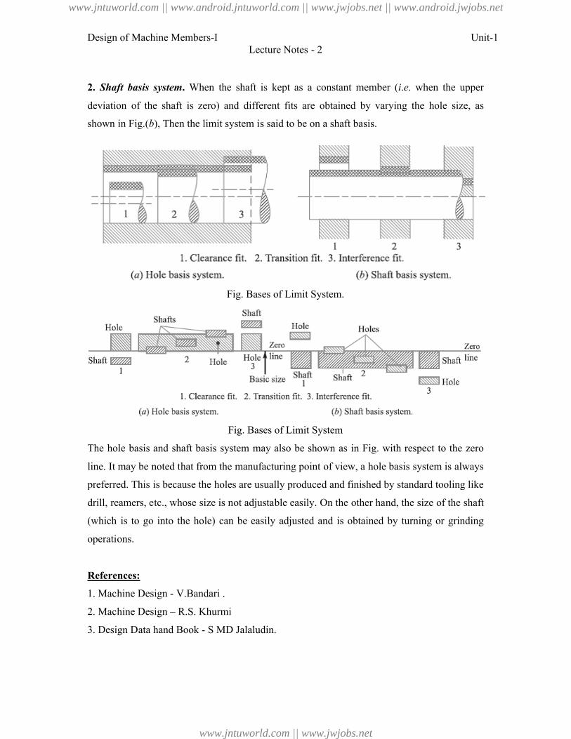
1. Hole basis system. When the hole is kept as a constant member (i.e. when the lower
deviation of the hole is zero) and different fits are obtained by varying the shaft size, as
shown in Fig. (a), then the limit system is said to be on a hole basis.
www.jntuworld.com || www.android.jntuworld.com || www.jwjobs.net || www.android.jwjobs.net
www.jntuworld.com || www.jwjobs.net
Design of Machine Members-I
2. Shaft basis system. When the shaft is kept as a constant member (
deviation of the shaft is zero) and different fits are obtained by varying the hole size, as
shown in Fig.(b), Then the limit system is said to be on a shaft basis.
The hole basis and shaft basis system may also be shown as in Fig. with respect to the zero
line. It may be noted that from the
preferred. This is because the holes are usually produced and finished by standard tooling like
drill, reamers, etc., whose size is not adjustable easily. On the other hand, the size of the shaft
(which is to go into the hole) can be easily adjusted and is obtained by turning or grinding
operations.
References:
1. Machine Design - V.Bandari .
2. Machine Design – R.S. Khurmi
3. Design Data hand Book - S MD Jalaludin.
Lecture Notes - 2
When the shaft is kept as a constant member (i.e. when the upper
deviation of the shaft is zero) and different fits are obtained by varying the hole size, as
), Then the limit system is said to be on a shaft basis.
Fig. Bases of Limit System.
Fig. Bases of Limit System
The hole basis and shaft basis system may also be shown as in Fig. with respect to the zero
line. It may be noted that from the manufacturing point of view, a hole basis system is always
preferred. This is because the holes are usually produced and finished by standard tooling like
drill, reamers, etc., whose size is not adjustable easily. On the other hand, the size of the shaft
which is to go into the hole) can be easily adjusted and is obtained by turning or grinding
V.Bandari .
R.S. Khurmi
S MD Jalaludin.
Unit-1
. when the upper
deviation of the shaft is zero) and different fits are obtained by varying the hole size, as
The hole basis and shaft basis system may also be shown as in Fig. with respect to the zero
manufacturing point of view, a hole basis system is always
preferred. This is because the holes are usually produced and finished by standard tooling like
drill, reamers, etc., whose size is not adjustable easily. On the other hand, the size of the shaft
which is to go into the hole) can be easily adjusted and is obtained by turning or grinding
www.jntuworld.com || www.android.jntuworld.com || www.jwjobs.net || www.android.jwjobs.net
www.jntuworld.com || www.jwjobs.net
Design of Machine Members-I
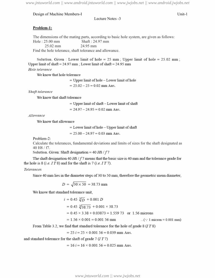
Problem-1:
The dimensions of the mating parts, according to basic hole system, are given as Hole : 25.00 mm Shaft : 24.97 mm
25.02 mm 24.95 mmFind the hole tolerance, shaft tolerance and allowance.
Problem-2:Calculate the tolerances, fundamental deviations and limits of sizes for the shaft designated as 40 H8 / f7.
Lecture Notes -3
The dimensions of the mating parts, according to basic hole system, are given as Shaft : 24.97 mm
24.95 mmFind the hole tolerance, shaft tolerance and allowance.
fundamental deviations and limits of sizes for the shaft designated as
Unit-1
The dimensions of the mating parts, according to basic hole system, are given as follows:
fundamental deviations and limits of sizes for the shaft designated as
www.jntuworld.com || www.android.jntuworld.com || www.jwjobs.net || www.android.jwjobs.net
www.jntuworld.com || www.jwjobs.net
Design of Machine Members-I
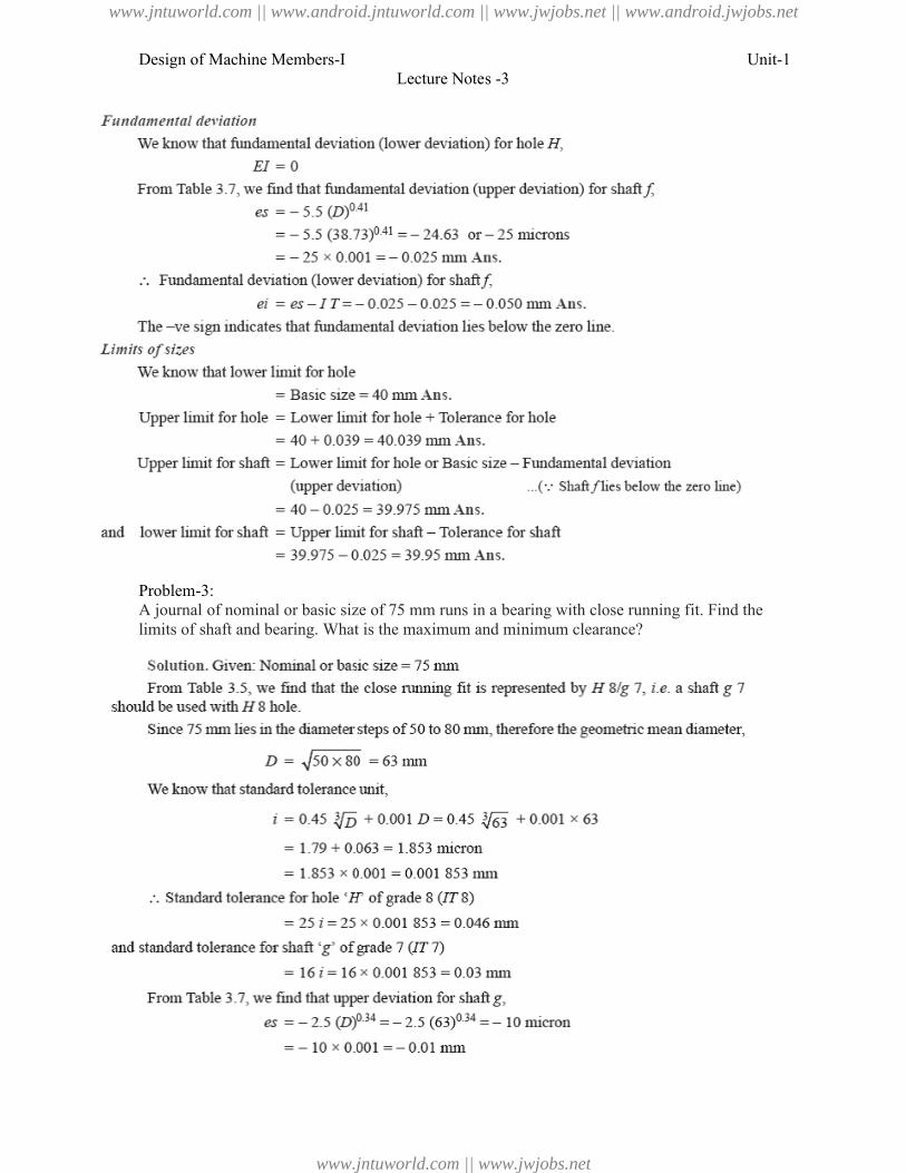
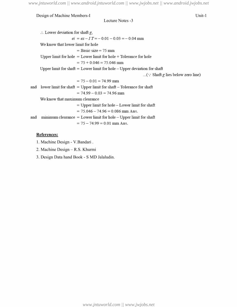
Problem-3:A journal of nominal or basic size of 75 mm runs in a bearing with close running fit. Find the limits of shaft and bearing. What is the maximum and minimum c
Lecture Notes -3
A journal of nominal or basic size of 75 mm runs in a bearing with close running fit. Find the limits of shaft and bearing. What is the maximum and minimum clearance?
Unit-1
A journal of nominal or basic size of 75 mm runs in a bearing with close running fit. Find the
www.jntuworld.com || www.android.jntuworld.com || www.jwjobs.net || www.android.jwjobs.net
www.jntuworld.com || www.jwjobs.net
Design of Machine Members-I
References:
1. Machine Design - V.Bandari .
2. Machine Design – R.S. Khurmi
3. Design Data hand Book - S MD Jalaludin.
Lecture Notes -3
.
R.S. Khurmi
S MD Jalaludin.
Unit-1
www.jntuworld.com || www.android.jntuworld.com || www.jwjobs.net || www.android.jwjobs.net
www.jntuworld.com || www.jwjobs.net
Design of Machine Members-I
Stress
When some external system of forces or loads acts on a body, the internal forces (equal and
opposite) are set up at various sections of the body, which resist the external forces. This
internal force per unit area at any section of the body is known as
stress. It is denoted by a Greek letter sigma (
Stress,
Where P = Force or load acting on a body, and
A = Cross
In S.I. units, the stress is usually expressed in Pas
practice, we use bigger units of stress
1 MPa = 1 × 10
And 1 GPa = 1 × 10
Strain
When a system of forces or loads act on a body, it undergoes some deformation. This
deformation per unit length is known as
Greek letter epsilon (ε). Mathematically,
Strain, ε= δl / l or
Where δl = Change in length of the body, and
l= Original length of the body.
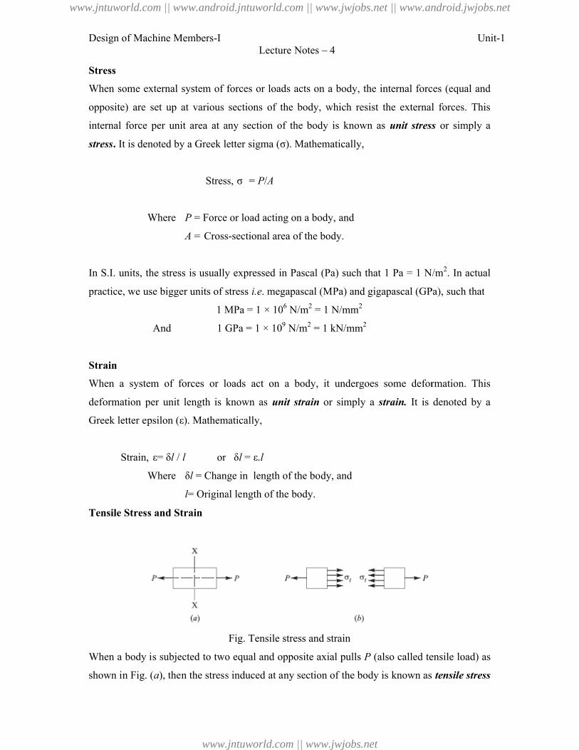
Tensile Stress and Strain
When a body is subjected to two equal and opposite axial pulls
shown in Fig. (a), then the stress induced at any section of the body is known as
Lecture Notes – 4
When some external system of forces or loads acts on a body, the internal forces (equal and
opposite) are set up at various sections of the body, which resist the external forces. This
internal force per unit area at any section of the body is known as unit stress
It is denoted by a Greek letter sigma (σ). Mathematically,
Stress, σ = P/A
= Force or load acting on a body, and
Cross-sectional area of the body.
In S.I. units, the stress is usually expressed in Pascal (Pa) such that 1 Pa = 1 N/m
practice, we use bigger units of stress i.e. megapascal (MPa) and gigapascal (GPa), such that
1 MPa = 1 × 10⁶ N/m2 = 1 N/mm2
1 GPa = 1 × 10⁹ N/m2 = 1 kN/mm2
When a system of forces or loads act on a body, it undergoes some deformation. This
deformation per unit length is known as unit strain or simply a strain. It is denoted by a
). Mathematically,
or δl = ε.l
= Change in length of the body, and
= Original length of the body.
Fig. Tensile stress and strain
When a body is subjected to two equal and opposite axial pulls P (also called tensile load) as
), then the stress induced at any section of the body is known as
Unit-1
When some external system of forces or loads acts on a body, the internal forces (equal and
opposite) are set up at various sections of the body, which resist the external forces. This
t stress or simply a
(Pa) such that 1 Pa = 1 N/m2. In actual
. megapascal (MPa) and gigapascal (GPa), such that
When a system of forces or loads act on a body, it undergoes some deformation. This
It is denoted by a
(also called tensile load) as
), then the stress induced at any section of the body is known as tensile stress
www.jntuworld.com || www.android.jntuworld.com || www.jwjobs.net || www.android.jwjobs.net
www.jntuworld.com || www.jwjobs.net
Design of Machine Members-I Unit-1Lecture Notes – 4
as shown in Fig. (b). A little consideration will show that due to the tensile load, there will be
a decrease in cross-sectional area and an increase in length of the body. The ratio of the
increase in length to the original length is known as tensile strain.
Let P = Axial tensile force acting on the body,
A = Cross-sectional area of the body,
l = Original length, and
δl = Increase in length.
Then Tensile stress, σt = P/A
and tensile strain, εt = δl / l
Young's Modulus or Modulus of Elasticity
Hooke's law* states that when a material is loaded within elastic limit, the stress is directly
proportional to strain, i.e.
where E is a constant of proportionality known as Young's modulus or modulus of elasticity.
In S.I. units, it is usually expressed in GPa i.e. GN/m2 or kN/mm2. It may be noted that
Hooke's law holds good for tension as well as compression.
The following table shows the values of modulus of elasticity or Young's modulus (E) for the
materials commonly used in engineering practice.
Values of E for the commonly used engineering materials.
Material Modulus of elasticity (E) in
GPai.e. GN/m2 for kN/mm2
Steel and Nickel 200 to 220
Wrought iron 190 to 200
Cast iron 100 to 160
Copper 90 to 110
Brass 80 to 90
Aluminium 60 to 80
Timber 10
www.jntuworld.com || www.android.jntuworld.com || www.jwjobs.net || www.android.jwjobs.net
www.jntuworld.com || www.jwjobs.net
Design of Machine Members-I
Shear Stress and Strain
When a body is subjected to two equal and opposite forces acting tangentially across the
resisting section, as a result of which the body tends to shear off the section, then the stress
induced is called shear stress.
Fig.
The corresponding strain is known as
deformation accompanying the shear stress. The shear stress and shear strain are denoted by
the Greek letters tau (τ) and phi (
Shear stress,
Consider a body consisting of two plates connec
case, the tangential force P tends to shear off the rivet at one cross
(b). It may be noted that when the tangential force is resisted by one cross
(or when shearing takes place at one cross
in single shear. In such a case, the area resisting the shear off the rivet,
And shear stress on the rivet cross
Now let us consider two plates connected by the two c
case, the tangential force P tends to shear off the rivet at two cro
(b). It may be noted that when the tangential force is resisted by two cross
Lecture Notes – 4
When a body is subjected to two equal and opposite forces acting tangentially across the
resisting section, as a result of which the body tends to shear off the section, then the stress
Single shearing of a riveted joint.
The corresponding strain is known as shear strain and it is measured by the angular
deformation accompanying the shear stress. The shear stress and shear strain are denoted by
) and phi (φ) respectively. Mathematically,
Tangential force
Shear stress, τ =
Resisting area
Consider a body consisting of two plates connected by a rivet as shown in Fig.
tends to shear off the rivet at one cross-section as shown in Fig.
). It may be noted that when the tangential force is resisted by one cross-section of the rivet
(or when shearing takes place at one cross-section of the rivet), then the rivets are said to be
In such a case, the area resisting the shear off the rivet,
2
4dA
And shear stress on the rivet cross-section
22
4
4d
P
d
P
A
P
Now let us consider two plates connected by the two cover plates as shown in Fig.
tends to shear off the rivet at two cross-sections as shown in Fig.
(b). It may be noted that when the tangential force is resisted by two cross-sections of the
Unit-1
When a body is subjected to two equal and opposite forces acting tangentially across the
resisting section, as a result of which the body tends to shear off the section, then the stress
and it is measured by the angular
deformation accompanying the shear stress. The shear stress and shear strain are denoted by
ted by a rivet as shown in Fig. (a). In this
section as shown in Fig.
section of the rivet
section of the rivet), then the rivets are said to be
over plates as shown in Fig. (a). In this
sections as shown in Fig.
sections of the
www.jntuworld.com || www.android.jntuworld.com || www.jwjobs.net || www.android.jwjobs.net
www.jntuworld.com || www.jwjobs.net
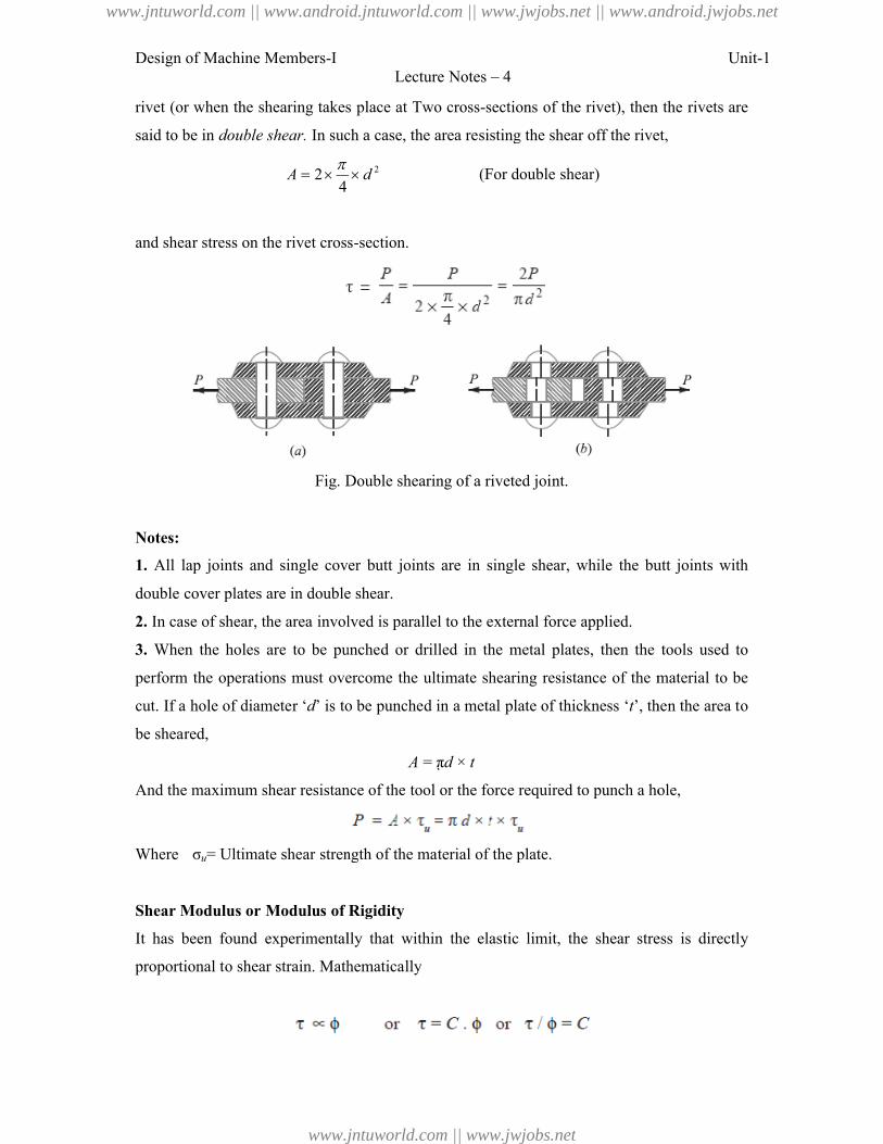
Design of Machine Members-I
rivet (or when the shearing takes place at Two cross
said to be in double shear. In such a case, the area resisting the shear off the rivet,
42A
and shear stress on the rivet cross
Fig. Double shearing of a riveted joint.
Notes:
1. All lap joints and single cover butt joints are in single shear, while the butt joints with
double cover plates are in double shear.
2. In case of shear, the area involved is parallel to the external force applied.
3. When the holes are to be punched or d
perform the operations must overcome the ultimate shearing resistance of the material to be
cut. If a hole of diameter ‘d’ is to be punched in a metal plate of thickness ‘
be sheared,
And the maximum shear resistance of the tool or the force required to punch a hole,
Where σu= Ultimate shear strength of the material of the plate.
Shear Modulus or Modulus of Rigidity
It has been found experimentally that within the elas
proportional to shear strain. Mathematically
Lecture Notes – 4
rivet (or when the shearing takes place at Two cross-sections of the rivet), then the rivets are
In such a case, the area resisting the shear off the rivet,
2d (For double shear)
and shear stress on the rivet cross-section.
. Double shearing of a riveted joint.
All lap joints and single cover butt joints are in single shear, while the butt joints with
double cover plates are in double shear.
In case of shear, the area involved is parallel to the external force applied.
When the holes are to be punched or drilled in the metal plates, then the tools used to
perform the operations must overcome the ultimate shearing resistance of the material to be
’ is to be punched in a metal plate of thickness ‘t’, then the area to
A = πd × t
And the maximum shear resistance of the tool or the force required to punch a hole,
= Ultimate shear strength of the material of the plate.
Shear Modulus or Modulus of Rigidity
It has been found experimentally that within the elastic limit, the shear stress is directly
proportional to shear strain. Mathematically
Unit-1
, then the rivets are
In such a case, the area resisting the shear off the rivet,
All lap joints and single cover butt joints are in single shear, while the butt joints with
rilled in the metal plates, then the tools used to
perform the operations must overcome the ultimate shearing resistance of the material to be
’, then the area to
And the maximum shear resistance of the tool or the force required to punch a hole,
tic limit, the shear stress is directly
www.jntuworld.com || www.android.jntuworld.com || www.jwjobs.net || www.android.jwjobs.net
www.jntuworld.com || www.jwjobs.net
Design of Machine Members-I
Where τ= Shear stress,
φ= Shear strain, and
C = Constant of proportionality, known as shear modulus or modulus of rigidity. It is
also denoted by N or G.
The following table shows the values of modulus of rigidity (
use:
Values of C for the commonly used materials
Material Modulus of rigidity (C) in GPa i.e. G
Steel 80 to 100
Wrought iron 80 to 90
Cast iron 40 to
Copper 30 to 50
Brass 30 to 50
Timber 10
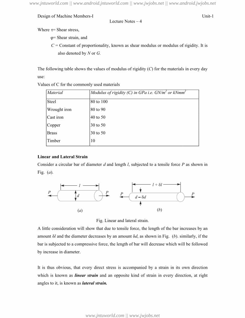
Linear and Lateral Strain
Consider a circular bar of diameter
Fig. (a).
Fig. Linear and
A little consideration will show that due to tensile force, the length of the bar increases by an
amount δl and the diameter decreases by an amount
bar is subjected to a compressive force, the length of bar will
by increase in diameter.
It is thus obvious, that every direct stress is accompanied by a strain in its own direction
which is known as linear strain
angles to it, is known as lateral strain.
Lecture Notes – 4
= Constant of proportionality, known as shear modulus or modulus of rigidity. It is
G.
following table shows the values of modulus of rigidity (C) for the materials in every day
commonly used materials
Modulus of rigidity (C) in GPa i.e. GN/m2 or kNmm
80 to 100
80 to 90
40 to 50
30 to 50
30 to 50
Consider a circular bar of diameter d and length l, subjected to a tensile force P
Fig. Linear and lateral strain.
A little consideration will show that due to tensile force, the length of the bar increases by an
and the diameter decreases by an amount δd, as shown in Fig. (b). similarly
bar is subjected to a compressive force, the length of bar will decrease which will be followed
It is thus obvious, that every direct stress is accompanied by a strain in its own direction
linear strain and an opposite kind of strain in every direction, at right
lateral strain.
Unit-1
= Constant of proportionality, known as shear modulus or modulus of rigidity. It is
) for the materials in every day
or kNmm2
P as shown in
A little consideration will show that due to tensile force, the length of the bar increases by an
similarly, if the
decrease which will be followed
It is thus obvious, that every direct stress is accompanied by a strain in its own direction
and an opposite kind of strain in every direction, at right
www.jntuworld.com || www.android.jntuworld.com || www.jwjobs.net || www.android.jwjobs.net
www.jntuworld.com || www.jwjobs.net

Design of Machine Members-I Unit-1Lecture Notes – 4
4.18 Poisson's Ratio
It has been found experimentally that when a body is stressed within elastic limit, the lateral
strain bears a constant ratio to the linear strain, Mathematically,
ConstantinLinearStra
ainLateralStr
This constant is known as Poisson's ratio and is denoted by 1/m or .
Following are the values of Poisson's ratio for some of the materials commonly used in
engineering practice.
Values of Poisson’s ratio for commonly used materials
S.No. Material Poisson 's ratio
(1/m or )
1 Steel 0.25 to 0.33
2 Cast iron 0.23 to 0.27
3 Copper 0.31 to 0.34
4 Brass 0.32 to 0.42
5 Aluminium 0.32 to 0.36
6 Concrete 0.08 to 0.18
7 Rubber 0.45 to 0.50
Volumetric Strain
When a body is subjected to a system of forces, it undergoes some changes in its dimensions.
In other words, the volume of the body is changed. The ratio of the change in volume to the
original volume is known as volumetric strain. Mathematically, volumetric strain,
VVv /
Where δV = Change in volume, and V = Original volume
Notes : 1. Volumetric strain of a rectangular body subjected to an axial force is given as
2. Volumetric strain of a rectangular body subjected to three mutually perpendicular forces is
given by
www.jntuworld.com || www.android.jntuworld.com || www.jwjobs.net || www.android.jwjobs.net
www.jntuworld.com || www.jwjobs.net
Design of Machine Members-I Unit-1Lecture Notes – 4
where εx, εy and εz are the strains in the directions x-axis, y-axis and z-axis respectively.
Bulk Modulus
When a body is subjected to three mutually perpendicular stresses, of equal intensity, then the
ratio of the direct stress to the corresponding volumetric strain is known as bulk modulus. It
is usually denoted by K. Mathematically, bulk modulus,
Relation Between Bulk Modulus and Young’s Modulus
The bulk modulus (K) and Young's modulus (E) are related by the following relation,
Relation between Young’s Modulus and Modulus of Rigidity
The Young's modulus (E) and modulus of rigidity (G) are related by the following relation,
Factor of Safety
It is defined, in general, as the ratio of the maximum stress to the working stress.
Mathematically,
Factor of safety = Maximum stress/ Working or design stress
In case of ductile materials e.g. mild steel, where the yield point is clearly defined, the factor
of safety is based upon the yield point stress. In such cases,
Factor of safety = Yield point stress/ Working or design stress
In case of brittle materials e.g. cast iron, the yield point is not well defined as for ductile
materials. Therefore, the factor of safety for brittle materials is based on ultimate stress.
Factor of safety = Ultimate stress/ Working or design stress
This relation may also be used for ductile materials.
The above relations for factor of safety are for static loading.
www.jntuworld.com || www.android.jntuworld.com || www.jwjobs.net || www.android.jwjobs.net
www.jntuworld.com || www.jwjobs.net
Design of Machine Members-I
Problem:
A steel bar 2.4 m long and 30 mm square is elongated by a load of 500 kN. If poisson's ratio
is 0.25, find the increase in volume. Take E = 0.2 × 10
References:
1. Machine Design - V.Bandari .
2. Machine Design – R.S. Khurmi
3. Design Data hand Book - S MD Jalaludin.
Lecture Notes – 4
A steel bar 2.4 m long and 30 mm square is elongated by a load of 500 kN. If poisson's ratio
is 0.25, find the increase in volume. Take E = 0.2 × 10⁶ N/mm2.
V.Bandari .
R.S. Khurmi
S MD Jalaludin.
Unit-1
A steel bar 2.4 m long and 30 mm square is elongated by a load of 500 kN. If poisson's ratio
www.jntuworld.com || www.android.jntuworld.com || www.jwjobs.net || www.android.jwjobs.net
www.jntuworld.com || www.jwjobs.net
Design of Machine Members-I Unit-1Lecture Notes – 7
Stresses due to Change in Temperature—Thermal Stresses
Whenever there is some increase or decrease in the temperature of a body, it causes the body
to expand or contract. A little consideration will show that if the body is allowed to expand or
contract freely, with the rise or fall of the temperature, no stresses are induced in the body.
But, if the deformation of the body is prevented, some stresses are induced in the body. Such
stresses are known as thermal stresses.
Let l = Original length of the body,
t = Rise or fall of temperature, and
α = Coefficient of thermal expansion,
δl Increase or decrease in length,
If the ends of the body are fixed to rigid supports, so that its expansion is prevented, then
compressive strain induced in the body,
Thermal stress,
1. When a body is composed of two or different materials having different coefficient of
thermal expansions, then due to the rise in temperature, the material with higher coefficient of
thermal expansion will be subjected to compressive stress whereas the material with low
coefficient of expansion will be subjected to tensile stress.
2. When a thin tyre is shrunk on to a wheel of diameter D, its internal diameter d is a little
less than the wheel diameter. When the type is heated, its circumference π d will increase to π
D. In this condition, it is slipped on to the wheel. When it cools, it wants to return to its
original circumference π d, but the wheel if it is assumed to be rigid, prevents it from doing
so.
This strain is known as circumferential or hoop strain.
Therefore, Circumferential or hoop stress,
www.jntuworld.com || www.android.jntuworld.com || www.jwjobs.net || www.android.jwjobs.net
www.jntuworld.com || www.jwjobs.net
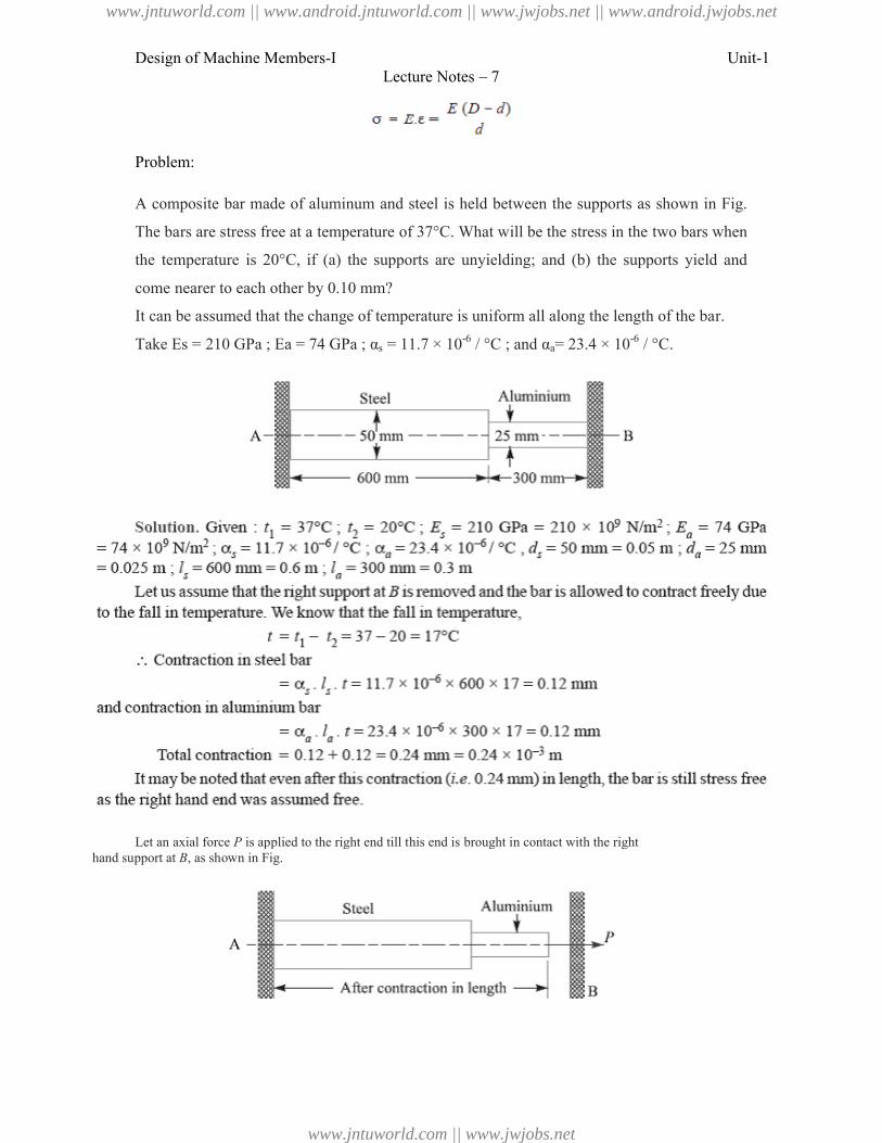
Design of Machine Members-I
Problem:
A composite bar made of aluminum and steel is held between the supports as
The bars are stress free at a temperature of 37°C. What will be the stress in the
the temperature is 20°C, if (a) the supports are unyielding; and (b) the supports yield
come nearer to each other by 0.10 mm?
It can be assumed that the change of temperature is uniform all along the length of the bar.
Take Es = 210 GPa ; Ea = 74 GPa ;
Let an axial force P is applied to the right end till this end is brought in contact with the righthand support at B, as shown in Fig.
Lecture Notes – 7
A composite bar made of aluminum and steel is held between the supports as shown in Fig.
The bars are stress free at a temperature of 37°C. What will be the stress in the two
the temperature is 20°C, if (a) the supports are unyielding; and (b) the supports yield
come nearer to each other by 0.10 mm?
It can be assumed that the change of temperature is uniform all along the length of the bar.
= 74 GPa ; αs = 11.7 × 10⁻⁶ / °C ; and αa= 23.4 × 10⁻⁶ / °C.
is applied to the right end till this end is brought in contact with the right
Unit-1
shown in Fig.
two bars when
the temperature is 20°C, if (a) the supports are unyielding; and (b) the supports yield and
It can be assumed that the change of temperature is uniform all along the length of the bar.
/ °C.
www.jntuworld.com || www.android.jntuworld.com || www.jwjobs.net || www.android.jwjobs.net
www.jntuworld.com || www.jwjobs.net
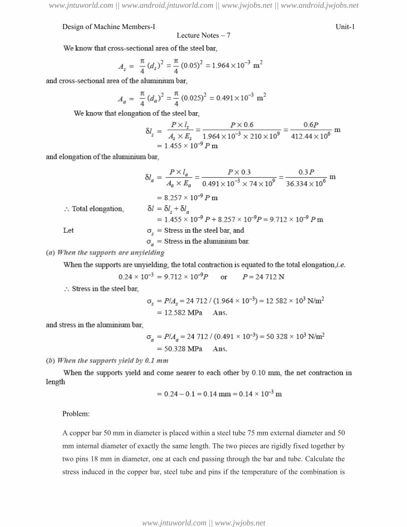
Design of Machine Members-I
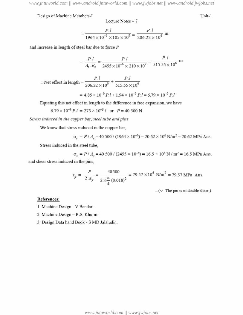
Problem:
A copper bar 50 mm in diameter is placed
mm internal diameter of exactly the same length. The two pieces are rigidly fixed
two pins 18 mm in diameter, one at each end passing through the bar and tube. Calculate
stress induced in the copper bar, steel tube and pins if the temperature of the combination is
Lecture Notes – 7
A copper bar 50 mm in diameter is placed within a steel tube 75 mm external diameter and 50
mm internal diameter of exactly the same length. The two pieces are rigidly fixed
two pins 18 mm in diameter, one at each end passing through the bar and tube. Calculate
the copper bar, steel tube and pins if the temperature of the combination is
Unit-1
diameter and 50
mm internal diameter of exactly the same length. The two pieces are rigidly fixed together by
two pins 18 mm in diameter, one at each end passing through the bar and tube. Calculate the
the copper bar, steel tube and pins if the temperature of the combination is
www.jntuworld.com || www.android.jntuworld.com || www.jwjobs.net || www.android.jwjobs.net
www.jntuworld.com || www.jwjobs.net
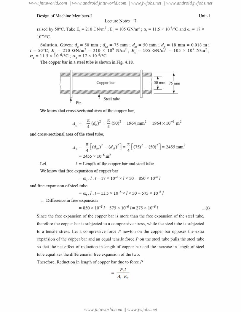
Design of Machine Members-I
raised by 50°C. Take Es = 210 GN/m
10-6/°C.
Since the free expansion of the copper bar is more than the free expansion
therefore the copper bar is subjected to a compressive stress,
to a tensile stress. Let a compressive force
expansion of the copper bar and an equal
so that the net effect of reduction in length of copper bar and the
tube equalizes the difference in free expansion of the
Therefore, Reduction in length of copper
Lecture Notes – 7
= 210 GN/m2 ; Ec = 105 GN/m2 ; αs = 11.5 × 10⁻⁶/°C and
copper bar is more than the free expansion of the steel tube,
is subjected to a compressive stress, while the steel tube is subjected
Let a compressive force P newton on the copper bar opposes the extra
expansion of the copper bar and an equal tensile force P on the steel tube pulls the
reduction in length of copper bar and the increase in length of steel
the difference in free expansion of the two.
Reduction in length of copper bar due to force P
Unit-1
/°C and αc = 17 ×
the steel tube,
while the steel tube is subjected
on the copper bar opposes the extra
on the steel tube pulls the steel tube
increase in length of steel
www.jntuworld.com || www.android.jntuworld.com || www.jwjobs.net || www.android.jwjobs.net
www.jntuworld.com || www.jwjobs.net
Design of Machine Members-I
References:
1. Machine Design - V.Bandari .
2. Machine Design – R.S. Khurmi
3. Design Data hand Book - S MD Jalaludin.
Lecture Notes – 7
V.Bandari .
R.S. Khurmi
S MD Jalaludin.
Unit-1
www.jntuworld.com || www.android.jntuworld.com || www.jwjobs.net || www.android.jwjobs.net
www.jntuworld.com || www.jwjobs.net
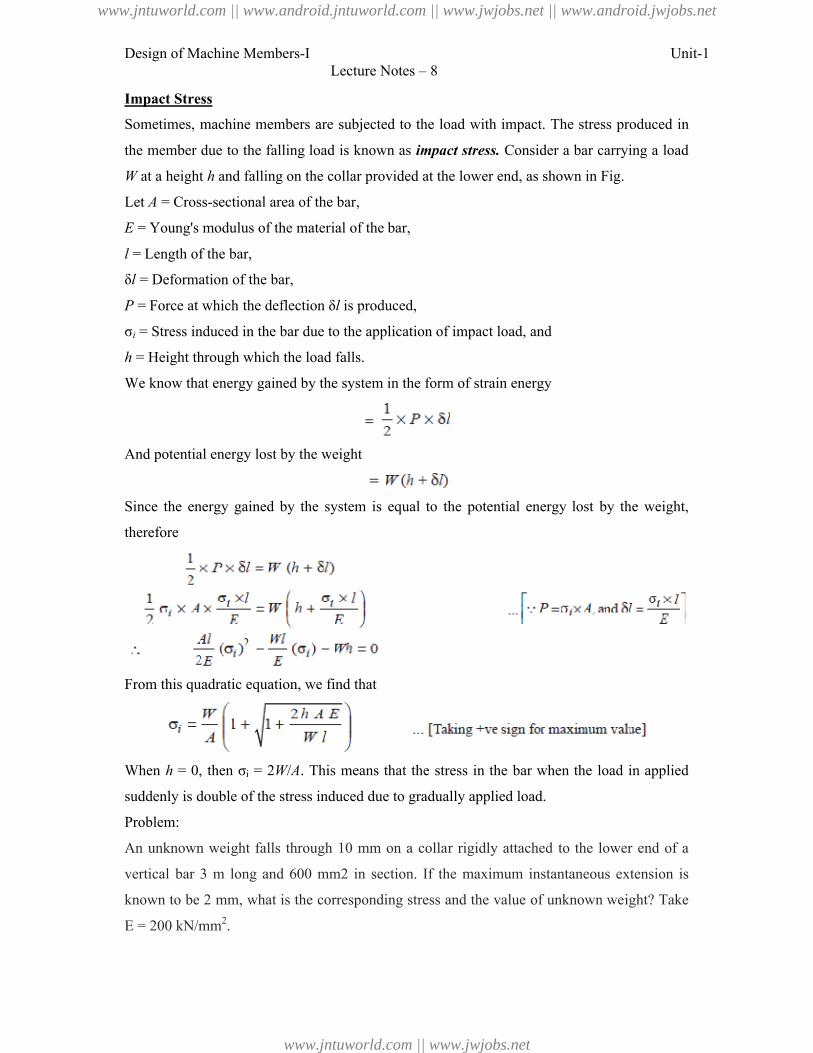
Design of Machine Members-I Unit-1Lecture Notes – 8
Impact Stress
Sometimes, machine members are subjected to the load with impact. The stress produced in
the member due to the falling load is known as impact stress. Consider a bar carrying a load
W at a height h and falling on the collar provided at the lower end, as shown in Fig.
Let A = Cross-sectional area of the bar,
E = Young's modulus of the material of the bar,
l = Length of the bar,
δl = Deformation of the bar,
P = Force at which the deflection δl is produced,
σi = Stress induced in the bar due to the application of impact load, and
h = Height through which the load falls.
We know that energy gained by the system in the form of strain energy
And potential energy lost by the weight
Since the energy gained by the system is equal to the potential energy lost by the weight,
therefore
From this quadratic equation, we find that
When h = 0, then σi = 2W/A. This means that the stress in the bar when the load in applied
suddenly is double of the stress induced due to gradually applied load.
Problem:
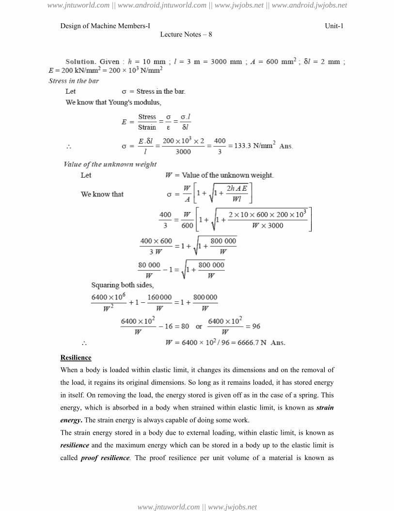
An unknown weight falls through 10 mm on a collar rigidly attached to the lower end of a
vertical bar 3 m long and 600 mm2 in section. If the maximum instantaneous extension is
known to be 2 mm, what is the corresponding stress and the value of unknown weight? Take
E = 200 kN/mm2.
www.jntuworld.com || www.android.jntuworld.com || www.jwjobs.net || www.android.jwjobs.net
www.jntuworld.com || www.jwjobs.net
Design of Machine Members-I
Resilience
When a body is loaded within elastic limit, it changes its dimensions and on the removal of
the load, it regains its original dimensions. So long as it remains loaded, it has stored energy
in itself. On removing the load, the energy stored is given off as in the case of a spring. This
energy, which is absorbed in a body when strained within elastic limit, is known as
energy. The strain energy is always capable of doing some work.
The strain energy stored in a body due to external loading, within elastic limit, is known as
resilience and the maximum energy which can be stored in a body up to the elastic limit is
called proof resilience. The proof resilience per unit volume of a material is known as
Lecture Notes – 8
When a body is loaded within elastic limit, it changes its dimensions and on the removal of
load, it regains its original dimensions. So long as it remains loaded, it has stored energy
the load, the energy stored is given off as in the case of a spring. This
absorbed in a body when strained within elastic limit, is known as
always capable of doing some work.
a body due to external loading, within elastic limit, is known as
and the maximum energy which can be stored in a body up to the elastic limit is
The proof resilience per unit volume of a material is known as
Unit-1
When a body is loaded within elastic limit, it changes its dimensions and on the removal of
load, it regains its original dimensions. So long as it remains loaded, it has stored energy
the load, the energy stored is given off as in the case of a spring. This
absorbed in a body when strained within elastic limit, is known as strain
a body due to external loading, within elastic limit, is known as
and the maximum energy which can be stored in a body up to the elastic limit is
The proof resilience per unit volume of a material is known as
www.jntuworld.com || www.android.jntuworld.com || www.jwjobs.net || www.android.jwjobs.net
www.jntuworld.com || www.jwjobs.net
Design of Machine Members-I
modulus of resilience. It is an important property of a material and gives capacity of the
material to bear impact or shocks. Mathematically, strain energy stored in a body due to
tensile or compressive load or resilience,
And Modulus of resilience
Where σ = Tensile or compressive stress,
V = Volume of the body, and
E = Young's modulus of the material of the body.
When a body is subjected to a shear load, then modulus of resilience (shear)
Where τ = Shear stress, and
C = Modulus of rigidity.
When the body is subjected to torsion, then modulus of resilience
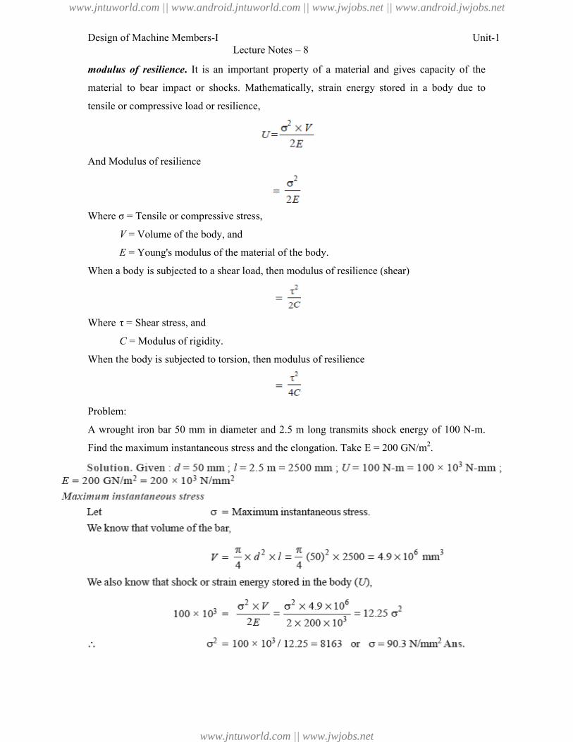
Problem:
A wrought iron bar 50 mm in diameter and 2.5 m long transmits shock energy
Find the maximum instantaneous stress and the elongation. Take E = 200 GN/m
Lecture Notes – 8
It is an important property of a material and gives capacity of the
shocks. Mathematically, strain energy stored in a body due to
tensile or compressive load or resilience,
nsile or compressive stress,
= Volume of the body, and
= Young's modulus of the material of the body.
When a body is subjected to a shear load, then modulus of resilience (shear)
subjected to torsion, then modulus of resilience
A wrought iron bar 50 mm in diameter and 2.5 m long transmits shock energy
Find the maximum instantaneous stress and the elongation. Take E = 200 GN/m2
Unit-1
It is an important property of a material and gives capacity of the
shocks. Mathematically, strain energy stored in a body due to
A wrought iron bar 50 mm in diameter and 2.5 m long transmits shock energy of 100 N-m. 2.
www.jntuworld.com || www.android.jntuworld.com || www.jwjobs.net || www.android.jwjobs.net
www.jntuworld.com || www.jwjobs.net
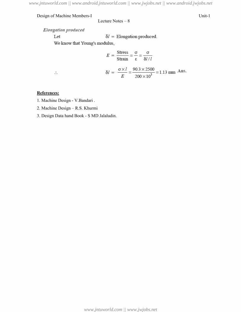
Design of Machine Members-I
References:
1. Machine Design - V.Bandari .
2. Machine Design – R.S. Khurmi
3. Design Data hand Book - S MD Jalaludin.
Lecture Notes – 8
V.Bandari .
R.S. Khurmi
S MD Jalaludin.
Unit-1
www.jntuworld.com || www.android.jntuworld.com || www.jwjobs.net || www.android.jwjobs.net
www.jntuworld.com || www.jwjobs.net
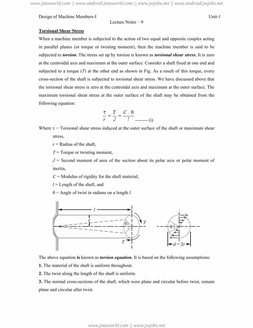
Design of Machine Members-I
Torsional Shear Stress
When a machine member is subjected to the action
in parallel planes (or torque or twisting moment), then the machine member
subjected to torsion. The stress set up by torsion
at the centroidal axis and maximum at the outer surface.
subjected to a torque (T) at the other end as shown in Fig. As a result
cross-section of the shaft is subjected
the torsional shear stress is zero at the centroidal axis and maximum at the outer surface. The
maximum torsional shear stress at the outer surface of the shaft may be obtained fro
following equation:
Where τ = Torsional shear stress induced at the outer surface of the shaft or maximum
stress,
r = Radius of the shaft,
T = Torque or twisting moment,
J = Second moment of area of the section about its polar ax
inertia,
C = Modulus of rigidity for the shaft material,
l = Length of the shaft, and
θ = Angle of twist in radians on a length
The above equation is known as
1. The material of the shaft is uniform throughout.
2. The twist along the length of the shaft is uniform.
3. The normal cross-sections of the shaft, which were plane and circular before twist, remain
plane and circular after twist.
Lecture Notes – 9
When a machine member is subjected to the action of two equal and opposite couples acting
(or torque or twisting moment), then the machine member
The stress set up by torsion is known as torsional shear stress
axis and maximum at the outer surface. Consider a shaft fixed at one end and
) at the other end as shown in Fig. As a result of this torque, every
shaft is subjected to torsional shear stress. We have discussed above that
the torsional shear stress is zero at the centroidal axis and maximum at the outer surface. The
maximum torsional shear stress at the outer surface of the shaft may be obtained fro
-------- (i)
τ = Torsional shear stress induced at the outer surface of the shaft or maximum
= Torque or twisting moment,
= Second moment of area of the section about its polar axis or polar moment of
= Modulus of rigidity for the shaft material,
= Length of the shaft, and
θ = Angle of twist in radians on a length l.
known as torsion equation. It is based on the following assumptions:
material of the shaft is uniform throughout.
The twist along the length of the shaft is uniform.
sections of the shaft, which were plane and circular before twist, remain
Unit-1
of two equal and opposite couples acting
is said to be
torsional shear stress. It is zero
Consider a shaft fixed at one end and
of this torque, every
to torsional shear stress. We have discussed above that
the torsional shear stress is zero at the centroidal axis and maximum at the outer surface. The
maximum torsional shear stress at the outer surface of the shaft may be obtained from the
τ = Torsional shear stress induced at the outer surface of the shaft or maximum shear
is or polar moment of
It is based on the following assumptions:
sections of the shaft, which were plane and circular before twist, remain
www.jntuworld.com || www.android.jntuworld.com || www.jwjobs.net || www.android.jwjobs.net
www.jntuworld.com || www.jwjobs.net
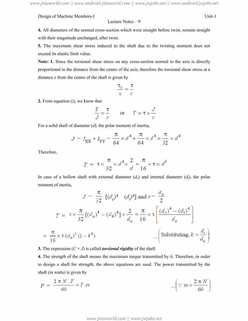
Design of Machine Members-I Unit-1Lecture Notes – 9
4. All diameters of the normal cross-section which were straight before twist, remain straight
with their magnitude unchanged, after twist.
5. The maximum shear stress induced in the shaft due to the twisting moment does not
exceed its elastic limit value.
Note: 1. Since the torsional shear stress on any cross-section normal to the axis is directly
proportional to the distance from the centre of the axis, therefore the torsional shear stress at a
distance x from the centre of the shaft is given by
2. From equation (i), we know that
For a solid shaft of diameter (d), the polar moment of inertia,
Therefore,
In case of a hollow shaft with external diameter (do) and internal diameter (di), the polar
moment of inertia,
3. The expression (C × J) is called torsional rigidity of the shaft.
4. The strength of the shaft means the maximum torque transmitted by it. Therefore, in order
to design a shaft for strength, the above equations are used. The power transmitted by the
shaft (in watts) is given by
www.jntuworld.com || www.android.jntuworld.com || www.jwjobs.net || www.android.jwjobs.net
www.jntuworld.com || www.jwjobs.net
Design of Machine Members-I
Where T = Torque transmitted in N
ω = Angular speed in rad/s.
Problem:
A shaft is transmitting 100 kW at 160 r.p.m. Find a suitable diameter for the
maximum torque transmitted exceeds the mean by 25%. Take maximum allowable shear
stress as 70 MPa.
Bending Stress
In engineering practice, the machine parts of structural members may be subjected to static or
dynamic loads which cause bending stress in the sections besides other types of stresses such
as tensile, compressive and shearing stresses.
moment M as shown in Fig.
The following assumptions are usually made while deriving the bending formula.
1. The material of the beam is perfectly homogeneous (
and isotropic (i.e. of equal elastic properties in all directions).
2. The material of the beam obeys Hooke’s law.
3. The transverse sections (i.e. BC
after bending also.
4. Each layer of the beam is free to expand or contract,
below it.
5. The Young’s modulus (E) is the same in tension and compression.
6. The loads are applied in the plane of bending.
Lecture Notes – 9
in N-m, and
ω = Angular speed in rad/s.
A shaft is transmitting 100 kW at 160 r.p.m. Find a suitable diameter for the
maximum torque transmitted exceeds the mean by 25%. Take maximum allowable shear
In engineering practice, the machine parts of structural members may be subjected to static or
dynamic loads which cause bending stress in the sections besides other types of stresses such
tensile, compressive and shearing stresses. Consider a straight beam subjected to a bending
assumptions are usually made while deriving the bending formula.
The material of the beam is perfectly homogeneous (i.e. of the same material throughout)
equal elastic properties in all directions).
The material of the beam obeys Hooke’s law.
BC or GH) which were plane before bending remain plane
Each layer of the beam is free to expand or contract, independently, of the layer, above or
) is the same in tension and compression.
The loads are applied in the plane of bending.
Unit-1
A shaft is transmitting 100 kW at 160 r.p.m. Find a suitable diameter for the shaft, if the
maximum torque transmitted exceeds the mean by 25%. Take maximum allowable shear
In engineering practice, the machine parts of structural members may be subjected to static or
dynamic loads which cause bending stress in the sections besides other types of stresses such
raight beam subjected to a bending
assumptions are usually made while deriving the bending formula.
. of the same material throughout)
) which were plane before bending remain plane
independently, of the layer, above or
www.jntuworld.com || www.android.jntuworld.com || www.jwjobs.net || www.android.jwjobs.net
www.jntuworld.com || www.jwjobs.net
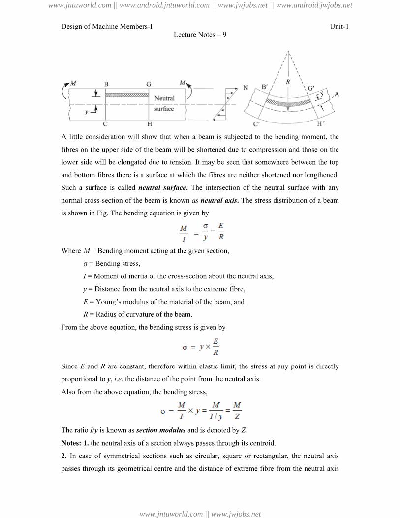
Design of Machine Members-I
A little consideration will show that when a beam is subjected to the bending moment, th
fibres on the upper side of the beam will be shortened due to compression and those on the
lower side will be elongated due to tension. It may be seen that somewhere between the top
and bottom fibres there is a surface at which the fibres are neither sho
Such a surface is called neutral
normal cross-section of the beam is known
is shown in Fig. The bending equation is given
Where M = Bending moment acting at the given section,
σ = Bending stress,
I = Moment of inertia of the cross
y = Distance from the neutral axis to the extreme fibre,
E = Young’s modulus of the material of the beam, and
R = Radius of curvature of the beam.
From the above equation, the bending stress is given by
Since E and R are constant, therefore within elastic limit, the stress at any point is directly
proportional to y, i.e. the distance of the point from the neutral
Also from the above equation, the bending stress,
The ratio I/y is known as section modulus
Notes: 1. the neutral axis of a section always passes through its
2. In case of symmetrical sections such as circular,
passes through its geometrical centre and
Lecture Notes – 9
A little consideration will show that when a beam is subjected to the bending moment, th
on the upper side of the beam will be shortened due to compression and those on the
be elongated due to tension. It may be seen that somewhere between the top
is a surface at which the fibres are neither shortened nor lengthened.
neutral surface. The intersection of the neutral surface with any
section of the beam is known as neutral axis. The stress distribution of a beam
is shown in Fig. The bending equation is given by
= Bending moment acting at the given section,
= Moment of inertia of the cross-section about the neutral axis,
= Distance from the neutral axis to the extreme fibre,
= Young’s modulus of the material of the beam, and
= Radius of curvature of the beam.
From the above equation, the bending stress is given by
are constant, therefore within elastic limit, the stress at any point is directly
. the distance of the point from the neutral axis.
Also from the above equation, the bending stress,
section modulus and is denoted by Z.
section always passes through its centroid.
sections such as circular, square or rectangular, the neutral axis
through its geometrical centre and the distance of extreme fibre from the neutral axis
Unit-1
A little consideration will show that when a beam is subjected to the bending moment, the
on the upper side of the beam will be shortened due to compression and those on the
be elongated due to tension. It may be seen that somewhere between the top
rtened nor lengthened.
The intersection of the neutral surface with any
The stress distribution of a beam
are constant, therefore within elastic limit, the stress at any point is directly
rectangular, the neutral axis
the neutral axis
www.jntuworld.com || www.android.jntuworld.com || www.jwjobs.net || www.android.jwjobs.net
www.jntuworld.com || www.jwjobs.net
Design of Machine Members-I
is y = d / 2, where d is the diameter in case of circular
rectangular section.
3. In case of unsymmetrical sections such as L
pass through its geometrical centre.
calculated and then the distance of the extreme fibres for
section is obtained. Out of these two values, the bigger value is used in bending equation.
Problem:
A beam of uniform rectangular cross
weighing 400 N at a distance of 300 m
the beam is 40 MPa. Find the width and depth of the beam,
Problem:
A cast iron pulley transmits 10 kW at 400 r.p.m. The diameter of the pulley is 1.2
it has four straight arms of elliptical cross
axis. Determine the dimensions of the arm if the allowable bending stress is 15 MPa
Lecture Notes – 9
is the diameter in case of circular section or depth in case of square or
sections such as L-section or T-section, the neutral axis does not
pass through its geometrical centre. In such cases, first of all the centroid of the section is
the distance of the extreme fibres for both lower and upper side of the
section is obtained. Out of these two values, the bigger value is used in bending equation.
A beam of uniform rectangular cross-section is fixed at one end and carries an electric motor
weighing 400 N at a distance of 300 mm from the fixed end. The maximum bending stress in
beam is 40 MPa. Find the width and depth of the beam, if depth is twice that of width.
A cast iron pulley transmits 10 kW at 400 r.p.m. The diameter of the pulley is 1.2
four straight arms of elliptical cross-section, in which the major axis is twice the
axis. Determine the dimensions of the arm if the allowable bending stress is 15 MPa
Unit-1
section or depth in case of square or
the neutral axis does not
of the section is
r and upper side of the
section is obtained. Out of these two values, the bigger value is used in bending equation.
electric motor
from the fixed end. The maximum bending stress in
if depth is twice that of width.
A cast iron pulley transmits 10 kW at 400 r.p.m. The diameter of the pulley is 1.2 metre and
section, in which the major axis is twice the minor
axis. Determine the dimensions of the arm if the allowable bending stress is 15 MPa.
www.jntuworld.com || www.android.jntuworld.com || www.jwjobs.net || www.android.jwjobs.net
www.jntuworld.com || www.jwjobs.net
Design of Machine Members-I
References:
1. Machine Design - V.Bandari .
2. Machine Design – R.S. Khurmi
3. Design Data hand Book - S MD Jalaludin.
Lecture Notes – 9
V.Bandari .
Khurmi
S MD Jalaludin.
Unit-1
www.jntuworld.com || www.android.jntuworld.com || www.jwjobs.net || www.android.jwjobs.net
www.jntuworld.com || www.jwjobs.net
Design of Machine Members-I
Principal Stresses and Principal Planes
In the previous chapter, we have discussed about the direct tensile and compressive stress as
well as simple shear. Also we have always referred the stress in a plane which is at right
angles to the line of action of the force.
strained material, there are three planes, mutually
direct stresses only and no shear
one will be maximum and the other
have no shear stress are known as
are known as principal stresses
known as planes of maximum shear.
Determination of Principal Stresses for a Member Subjected to Bi
When a member is subjected to bi
planes accompanied by a simple shear
as discussed below:
Consider a rectangular body
subjected to normal stresses σ1
stresses, a shear stress τ also acts.
the normal stress across any oblique
direction of σ2, as shown in Fig.
And tangential stress (i.e. shear stress) across the section
Since the planes of maximum and minimum normal stress (
shear stress, therefore the inclination of principal planes is obtained by equating τ
above equation (ii), i.e.
Lecture Notes – 10
Principal Stresses and Principal Planes
In the previous chapter, we have discussed about the direct tensile and compressive stress as
well as simple shear. Also we have always referred the stress in a plane which is at right
of the force. But it has been observed that at any point in a
three planes, mutually perpendicular to each other which carry
stresses only and no shear stress. It may be noted that out of these three direct
maximum and the other will be minimum. These perpendicular planes
are known as principal planes and the direct stresses along these planes
stresses. The planes on which the maximum shear stress act
known as planes of maximum shear.
Determination of Principal Stresses for a Member Subjected to Bi-axial Stress
When a member is subjected to bi-axial stress (i.e. direct stress in two mutually perpendicular
planes accompanied by a simple shear stress), then the normal and shear stresses are obtained
Consider a rectangular body ABCD of uniform cross-sectional area and unit thickness
1 and σ2 as shown in Fig. (a). In addition to these normal
stress τ also acts. It has been shown in books on ‘Strength of Materials
the normal stress across any oblique section such as EF inclined at an angle θ with the
, as shown in Fig. (a), is given by
. shear stress) across the section EF,
Since the planes of maximum and minimum normal stress (i.e. principal planes) have no
shear stress, therefore the inclination of principal planes is obtained by equating τ
Unit-1
In the previous chapter, we have discussed about the direct tensile and compressive stress as
well as simple shear. Also we have always referred the stress in a plane which is at right
that at any point in a
other which carry
out of these three direct stresses,
perpendicular planes which
stresses along these planes
stress act are
Stress
. direct stress in two mutually perpendicular
stress), then the normal and shear stresses are obtained
sectional area and unit thickness
). In addition to these normal
Strength of Materials’ that
inclined at an angle θ with the
. principal planes) have no
shear stress, therefore the inclination of principal planes is obtained by equating τ1 = 0 in the
www.jntuworld.com || www.android.jntuworld.com || www.jwjobs.net || www.android.jwjobs.net
www.jntuworld.com || www.jwjobs.net
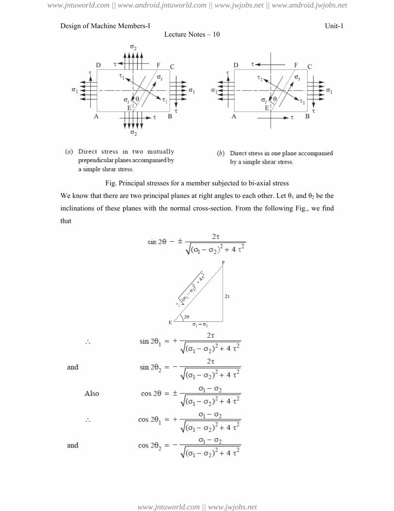
Design of Machine Members-I
Fig. Principal stresses for a member subjected to bi
We know that there are two principal planes at right angles to each other. Let θ
inclinations of these planes with the normal cross
that
Lecture Notes – 10
Principal stresses for a member subjected to bi-axial stress
We know that there are two principal planes at right angles to each other. Let θ1
inclinations of these planes with the normal cross-section. From the following
Unit-1
1 and θ2 be the
the following Fig., we find
www.jntuworld.com || www.android.jntuworld.com || www.jwjobs.net || www.android.jwjobs.net
www.jntuworld.com || www.jwjobs.net
Design of Machine Members-I
The maximum and minimum principal stresses may now be obtained by substituting the
values of sin 2θ and cos 2θ in equation
So, Maximum principal (or normal) stress,
And minimum principal (or normal) stress,
The planes of maximum shear stress are at right angles to each other and are inclined at 45°
to the principal planes. The maximum shear stress is given by
difference between the principal stresses,
Notes: 1. when a member is subjected to direct stress in one plane accompanied b
shear stress, then the principal stresses are obtained by substituting σ
and (vi).
2. In the above expression of σ
Therefore the nature of σt2 will be opposite to that of σ
compressive and vice-versa.
Application of Principal Stresses in Designing Machine Members
There are many cases in practice, in which machine members are
stresses due to simultaneous action of either tensile or compressive stresses combined with
shear stresses. In many shafts such as propeller shafts, C
or compressive stresses due to the external
Lecture Notes – 10
The maximum and minimum principal stresses may now be obtained by substituting the
of sin 2θ and cos 2θ in equation (i).
principal (or normal) stress,
minimum principal (or normal) stress,
shear stress are at right angles to each other and are inclined at 45°
the principal planes. The maximum shear stress is given by one-half the algebraic
the principal stresses, i.e.
a member is subjected to direct stress in one plane accompanied b
then the principal stresses are obtained by substituting σ2 = 0 in equation
In the above expression of σt2, the value of is more than
will be opposite to that of σt1, i.e. if σt1 is tensile then σ
Application of Principal Stresses in Designing Machine Members
There are many cases in practice, in which machine members are subjected to combined
due to simultaneous action of either tensile or compressive stresses combined with
many shafts such as propeller shafts, C-frames etc., there are direct tensile
due to the external force and shear stress due to torsion, which acts
Unit-1
The maximum and minimum principal stresses may now be obtained by substituting the
shear stress are at right angles to each other and are inclined at 45°
half the algebraic
a member is subjected to direct stress in one plane accompanied by a simple
= 0 in equation (iv), (v)
is more than σ1/2
is tensile then σt2 will be
subjected to combined
due to simultaneous action of either tensile or compressive stresses combined with
frames etc., there are direct tensile
force and shear stress due to torsion, which acts
www.jntuworld.com || www.android.jntuworld.com || www.jwjobs.net || www.android.jwjobs.net
www.jntuworld.com || www.jwjobs.net
Design of Machine Members-I
normal to direct tensile or compressive
simultaneously to torsion and bending. In
the combination of tensile or compressive stresses
results obtained in the previous article may be written as follows:
1. Maximum tensile stress,
2. Maximum compressive stress,
3. Maximum shear stress,
Where σt = Tensile stress due to direct load and bending,
σc = Compressive stress, and
τ = Shear stress due to torsion.
Notes: 1. When τ = 0 as in the case of thin cylindrical shell subjected in internal fluid
pressure, then σtmax = σt
2. When the shaft is subjected to an axial
moments as in the propeller shafts of ship and shafts for driving worm gears, then the stress
due to axial load must be added to the
stress or compressive stress (σt or σ
Problem:
A shaft, as shown in Fig., is subjected to a bending load of 3 kN, pure torque
and an axial pulling force of 15 kN
Lecture Notes – 10
normal to direct tensile or compressive stresses. The shafts like crank shafts, are subjected
simultaneously to torsion and bending. In such cases, the maximum principal stresses, due to
tensile or compressive stresses with shear stresses may be obtained.
results obtained in the previous article may be written as follows:
Maximum compressive stress,
due to direct load and bending,
= Compressive stress, and
τ = Shear stress due to torsion.
When τ = 0 as in the case of thin cylindrical shell subjected in internal fluid
When the shaft is subjected to an axial load (P) in addition to bending and twisting
propeller shafts of ship and shafts for driving worm gears, then the stress
due to axial load must be added to the bending stress (σb). This will give the resultant tensile
or σc) depending upon the type of axial load (i.e. pull or push).
, is subjected to a bending load of 3 kN, pure torque
and an axial pulling force of 15 kN. Calculate the stresses at A and B.
Unit-1
stresses. The shafts like crank shafts, are subjected
such cases, the maximum principal stresses, due to
with shear stresses may be obtained. The
When τ = 0 as in the case of thin cylindrical shell subjected in internal fluid
) in addition to bending and twisting
propeller shafts of ship and shafts for driving worm gears, then the stress
). This will give the resultant tensile
. pull or push).
of 1000 N-m
www.jntuworld.com || www.android.jntuworld.com || www.jwjobs.net || www.android.jwjobs.net
www.jntuworld.com || www.jwjobs.net
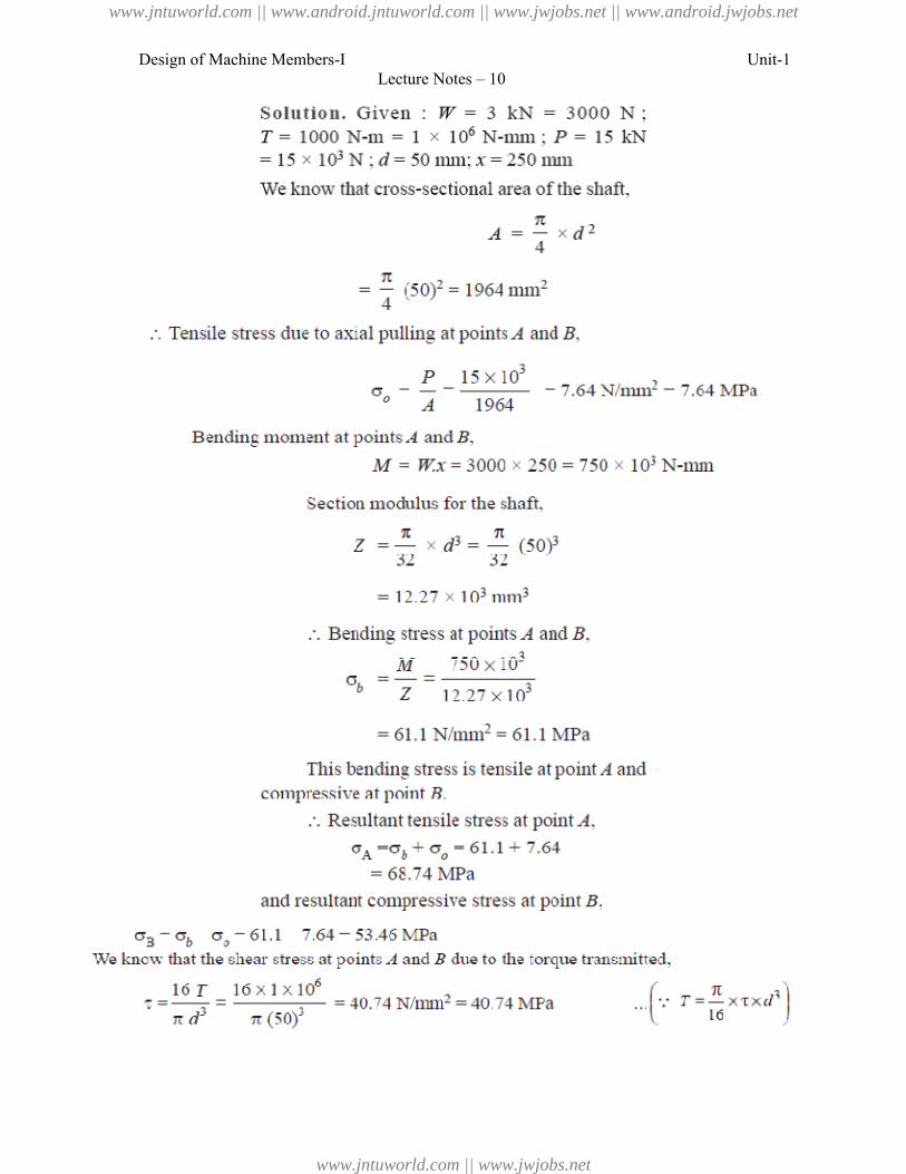
Design of Machine Members-ILecture Notes – 10
Unit-1
www.jntuworld.com || www.android.jntuworld.com || www.jwjobs.net || www.android.jwjobs.net
www.jntuworld.com || www.jwjobs.net
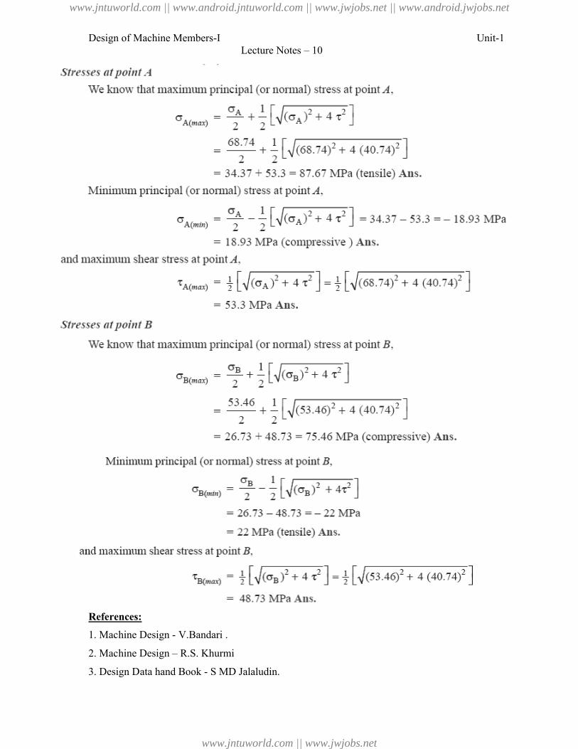
Design of Machine Members-I
References:
1. Machine Design - V.Bandari .
2. Machine Design – R.S. Khurmi
3. Design Data hand Book - S MD Jalaludin.
Lecture Notes – 10
V.Bandari .
R.S. Khurmi
S MD Jalaludin.
Unit-1
www.jntuworld.com || www.android.jntuworld.com || www.jwjobs.net || www.android.jwjobs.net
www.jntuworld.com || www.jwjobs.net
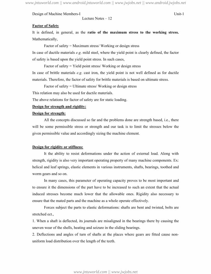
Design of Machine Members-I Unit-1Lecture Notes – 12
Factor of Safety
It is defined, in general, as the ratio of the maximum stress to the working stress.
Mathematically,
Factor of safety = Maximum stress/ Working or design stress
In case of ductile materials e.g. mild steel, where the yield point is clearly defined, the factor
of safety is based upon the yield point stress. In such cases,
Factor of safety = Yield point stress/ Working or design stress
In case of brittle materials e.g. cast iron, the yield point is not well defined as for ductile
materials. Therefore, the factor of safety for brittle materials is based on ultimate stress.
Factor of safety = Ultimate stress/ Working or design stress
This relation may also be used for ductile materials.
The above relations for factor of safety are for static loading.
Design for strength and rigidity:
Design for strength:
All the concepts discussed so far and the problems done are strength based, i.e., there
will be some permissible stress or strength and our task is to limit the stresses below the
given permissible value and accordingly sizing the machine element.
Design for rigidity or stiffness:
It the ability to resist deformations under the action of external load. Along with
strength, rigidity is also very important operating property of many machine components. Ex:
helical and leaf springs, elastic elements in various instruments, shafts, bearings, toothed and
worm gears and so on.
In many cases, this parameter of operating capacity proves to be most important and
to ensure it the dimensions of the part have to be increased to such an extent that the actual
induced stresses become much lower that the allowable ones. Rigidity also necessary to
ensure that the mated parts and the machine as a whole operate effectively.
Forces subject the parts to elastic deformations: shafts are bent and twisted, bolts are
stretched ect.,
1. When a shaft is deflected, its journals are misaligned in the bearings there by causing the
uneven wear of the shells, heating and seizure in the sliding bearings.
2. Deflections and angles of turn of shafts at the places where gears are fitted cause non-
uniform load distribution over the length of the teeth.
www.jntuworld.com || www.android.jntuworld.com || www.jwjobs.net || www.android.jwjobs.net
www.jntuworld.com || www.jwjobs.net
Design of Machine Members-I Unit-1Lecture Notes – 12
3. With the deflection of an insufficiently rigid shaft, the operating conditions or antifriction
bearings sharply deteriorate if the bearings cannot self aligning.
4. Rigidity is particularly important for ensuring the adequate accuracy of items produced on
machine tools.
Rigidity of machine elements is found with the help of formulae from the theory of
strength of materials. The actual displacements like deflections, angles of turn, angles of twist
should not be more that the allowable values. The most important design methods for
increasing the rigidity of machine elements are as follows.
a) The decrease in the arms of bending and twisting forces.
b) The incorporation of additional supports.
c) The application of cross sections which effectively resist torsion (closed tubular) and
bending (in which the cross section is removed as far as possible from the neutral axis).
d) The decrease of the length of the parts in tension and the increase of their cross section
area.
From the above it’s clear that the stiffness of a member depends not only on the shape and
size of its cross section but also on elastic modulus of the material used.
Preferred Numbers
When a machine is to be made in several sizes with different powers or capacities, it is
necessary to decide what capacities will cover a certain range efficiently with minimum
number of sizes. It has been shown by experience that a certain range can be covered
efficiently when it follows a geometrical progression with a constant ratio. The preferred
numbers are the conventionally rounded off values derived from geometric series including
the integral powers of 10 and having as common ratio of the following factors:
4020105 10,10,10,10
These ratios are approximately equal to 1.58, 1.26, 1.12 and 1.06. The series of preferred
numbers are designated as *R5, R10, R20 and R40 respectively. These four series are called
basic series. The other series called derived series may be obtained by simply multiplying or
dividing the basic sizes by 10, 100, etc. The preferred numbers in the series R5 are 1, 1.6, 2.5,
4.0 and 6.3.
References:
1. Machine Design - V.Bandari .
2. Machine Design – R.S. Khurmi
www.jntuworld.com || www.android.jntuworld.com || www.jwjobs.net || www.android.jwjobs.net
www.jntuworld.com || www.jwjobs.net
Design of Machine Members-I Unit-1Lecture Notes – 12
3. Design Data hand Book - S MD Jalaludin.
www.jntuworld.com || www.android.jntuworld.com || www.jwjobs.net || www.android.jwjobs.net
www.jntuworld.com || www.jwjobs.net
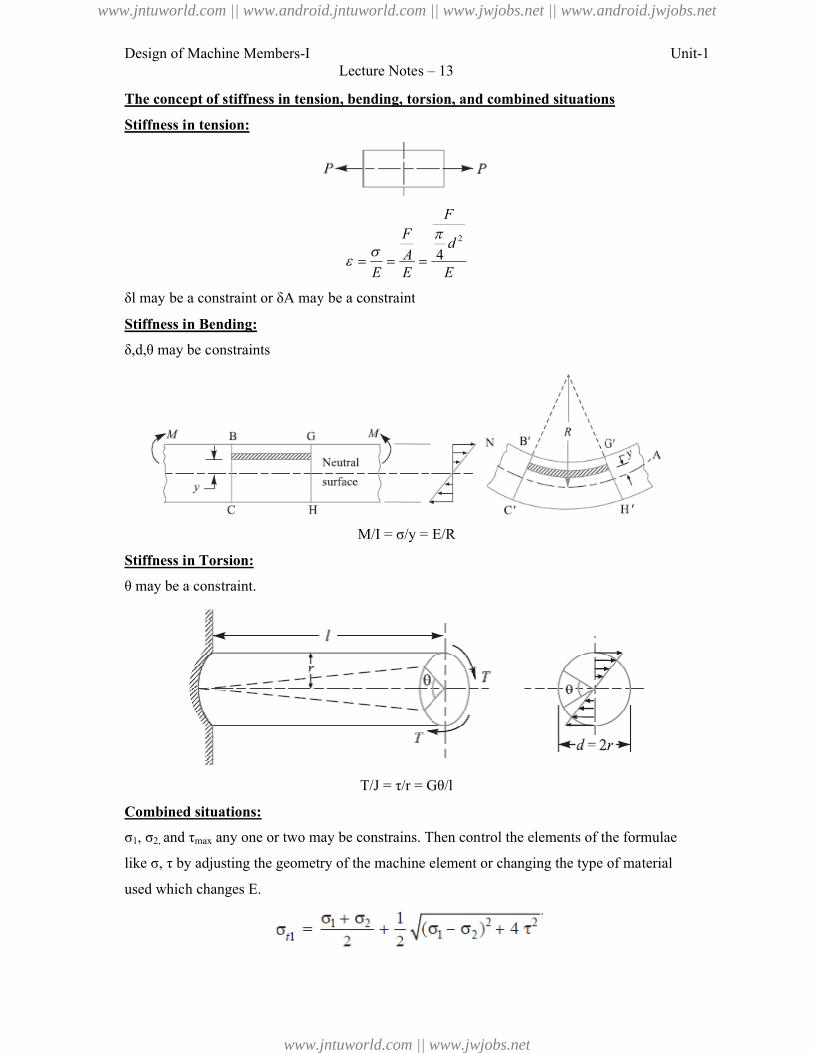
Design of Machine Members-I
The concept of stiffness in tension, bending, torsion, and combined situations
Stiffness in tension:
δl may be a constraint or δA may be a constraint
Stiffness in Bending:
δ,d,θ may be constraints
Stiffness in Torsion:
θ may be a constraint.
Combined situations:
σ1, σ2, and τmax any one or two may be constrains. Then control the elements of the formulae
like σ, τ by adjusting the geometry of the machine element or changing the type of material
used which changes E.
Lecture Notes – 13
The concept of stiffness in tension, bending, torsion, and combined situations
E
d
F
EA
F
E
2
4
δl may be a constraint or δA may be a constraint
M/I = σ/y = E/R
T/J = τ/r = Gθ/l
any one or two may be constrains. Then control the elements of the formulae
like σ, τ by adjusting the geometry of the machine element or changing the type of material
Unit-1
The concept of stiffness in tension, bending, torsion, and combined situations
any one or two may be constrains. Then control the elements of the formulae
like σ, τ by adjusting the geometry of the machine element or changing the type of material
www.jntuworld.com || www.android.jntuworld.com || www.jwjobs.net || www.android.jwjobs.net
www.jntuworld.com || www.jwjobs.net
Design of Machine Members-I Unit-1Lecture Notes – 13
References:
1. Machine Design - V.Bandari .
2. Machine Design – R.S. Khurmi
3. Design Data hand Book - S MD Jalaludin
www.jntuworld.com || www.android.jntuworld.com || www.jwjobs.net || www.android.jwjobs.net
www.jntuworld.com || www.jwjobs.net
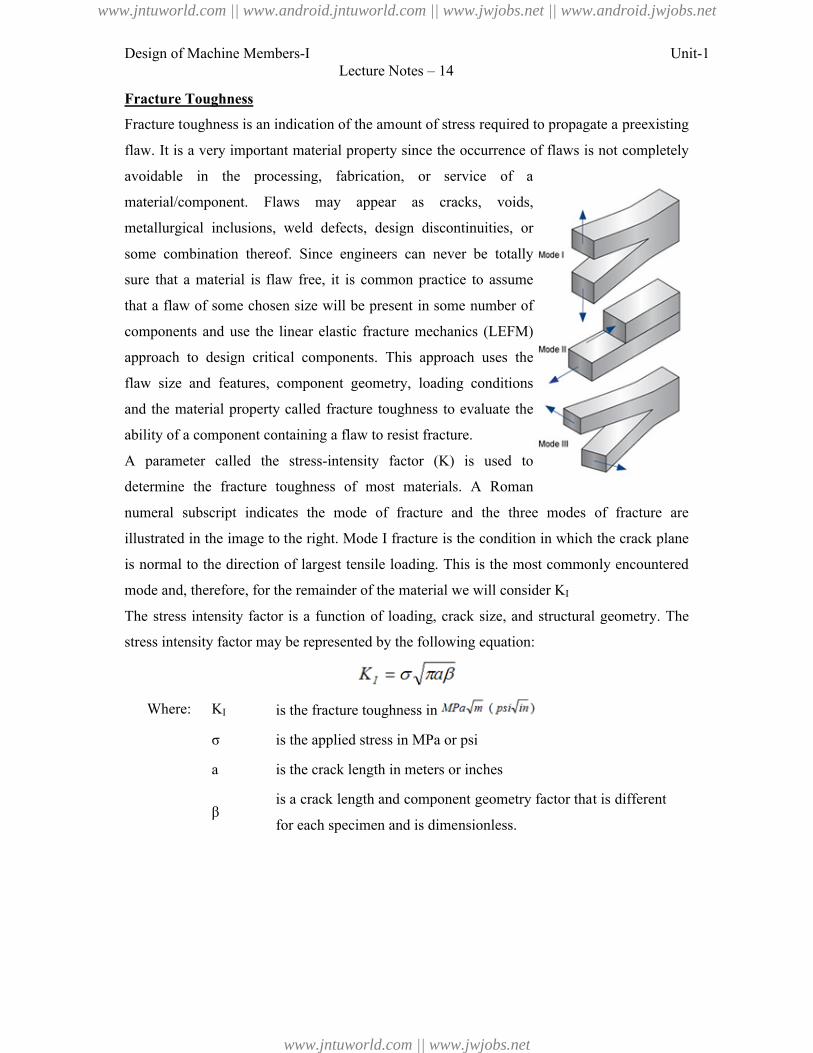
Design of Machine Members-I Unit-1Lecture Notes – 14
Fracture Toughness
Fracture toughness is an indication of the amount of stress required to propagate a preexisting
flaw. It is a very important material property since the occurrence of flaws is not completely
avoidable in the processing, fabrication, or service of a
material/component. Flaws may appear as cracks, voids,
metallurgical inclusions, weld defects, design discontinuities, or
some combination thereof. Since engineers can never be totally
sure that a material is flaw free, it is common practice to assume
that a flaw of some chosen size will be present in some number of
components and use the linear elastic fracture mechanics (LEFM)
approach to design critical components. This approach uses the
flaw size and features, component geometry, loading conditions
and the material property called fracture toughness to evaluate the
ability of a component containing a flaw to resist fracture.
A parameter called the stress-intensity factor (K) is used to
determine the fracture toughness of most materials. A Roman
numeral subscript indicates the mode of fracture and the three modes of fracture are
illustrated in the image to the right. Mode I fracture is the condition in which the crack plane
is normal to the direction of largest tensile loading. This is the most commonly encountered
mode and, therefore, for the remainder of the material we will consider KI
The stress intensity factor is a function of loading, crack size, and structural geometry. The
stress intensity factor may be represented by the following equation:
Where: KI is the fracture toughness in
σ is the applied stress in MPa or psi
a is the crack length in meters or inches
βis a crack length and component geometry factor that is different
for each specimen and is dimensionless.
www.jntuworld.com || www.android.jntuworld.com || www.jwjobs.net || www.android.jwjobs.net
www.jntuworld.com || www.jwjobs.net
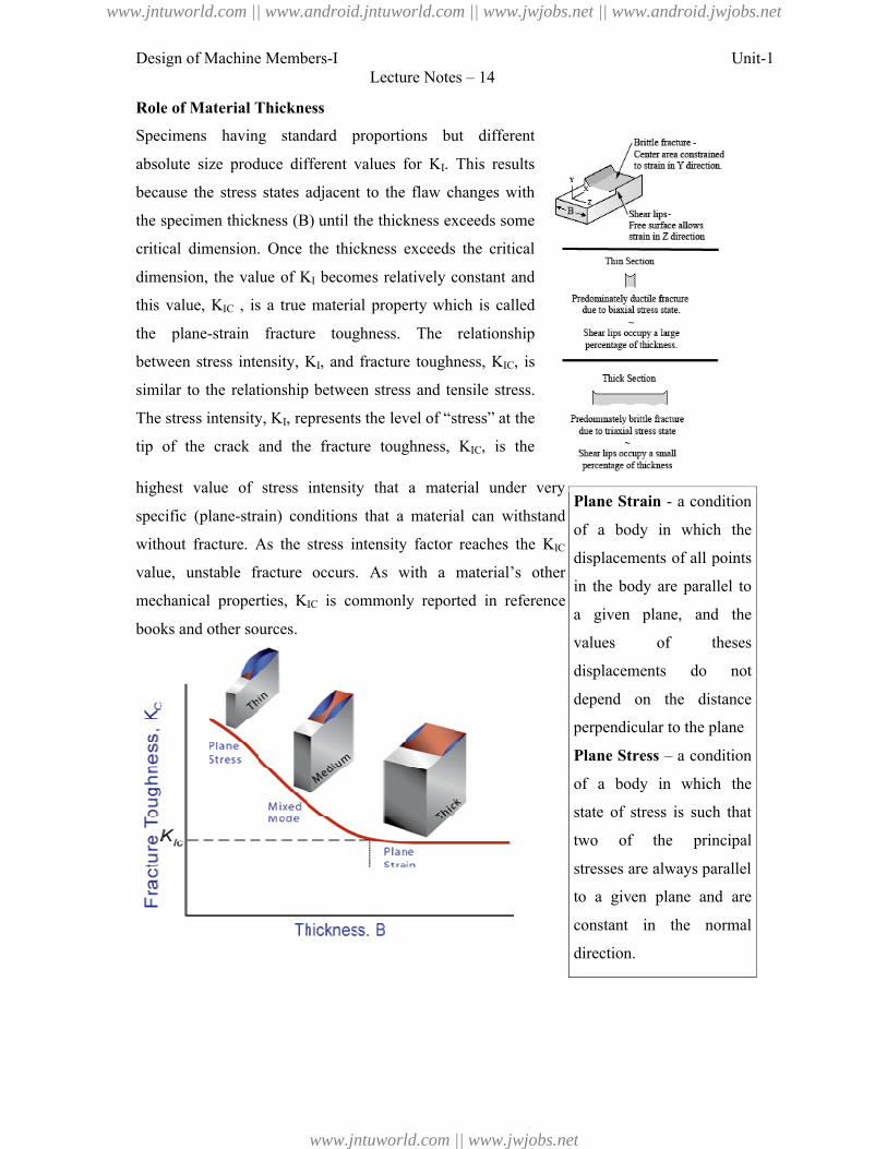
Design of Machine Members-I Unit-1Lecture Notes – 14
Role of Material Thickness
Specimens having standard proportions but different
absolute size produce different values for KI. This results
because the stress states adjacent to the flaw changes with
the specimen thickness (B) until the thickness exceeds some
critical dimension. Once the thickness exceeds the critical
dimension, the value of KI becomes relatively constant and
this value, KIC , is a true material property which is called
the plane-strain fracture toughness. The relationship
between stress intensity, KI, and fracture toughness, KIC, is
similar to the relationship between stress and tensile stress.
The stress intensity, KI, represents the level of “stress” at the
tip of the crack and the fracture toughness, KIC, is the
highest value of stress intensity that a material under very
specific (plane-strain) conditions that a material can withstand
without fracture. As the stress intensity factor reaches the KIC
value, unstable fracture occurs. As with a material’s other
mechanical properties, KIC is commonly reported in reference
books and other sources.
Plane Strain - a condition
of a body in which the
displacements of all points
in the body are parallel to
a given plane, and the
values of theses
displacements do not
depend on the distance
perpendicular to the plane
Plane Stress – a condition
of a body in which the
state of stress is such that
two of the principal
stresses are always parallel
to a given plane and are
constant in the normal
direction.
www.jntuworld.com || www.android.jntuworld.com || www.jwjobs.net || www.android.jwjobs.net
www.jntuworld.com || www.jwjobs.net
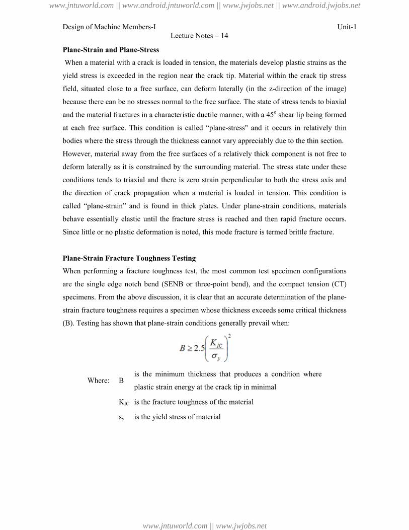
Design of Machine Members-I Unit-1Lecture Notes – 14
Plane-Strain and Plane-Stress
When a material with a crack is loaded in tension, the materials develop plastic strains as the
yield stress is exceeded in the region near the crack tip. Material within the crack tip stress
field, situated close to a free surface, can deform laterally (in the z-direction of the image)
because there can be no stresses normal to the free surface. The state of stress tends to biaxial
and the material fractures in a characteristic ductile manner, with a 45o shear lip being formed
at each free surface. This condition is called “plane-stress" and it occurs in relatively thin
bodies where the stress through the thickness cannot vary appreciably due to the thin section.
However, material away from the free surfaces of a relatively thick component is not free to
deform laterally as it is constrained by the surrounding material. The stress state under these
conditions tends to triaxial and there is zero strain perpendicular to both the stress axis and
the direction of crack propagation when a material is loaded in tension. This condition is
called “plane-strain” and is found in thick plates. Under plane-strain conditions, materials
behave essentially elastic until the fracture stress is reached and then rapid fracture occurs.
Since little or no plastic deformation is noted, this mode fracture is termed brittle fracture.
Plane-Strain Fracture Toughness Testing
When performing a fracture toughness test, the most common test specimen configurations
are the single edge notch bend (SENB or three-point bend), and the compact tension (CT)
specimens. From the above discussion, it is clear that an accurate determination of the plane-
strain fracture toughness requires a specimen whose thickness exceeds some critical thickness
(B). Testing has shown that plane-strain conditions generally prevail when:
Where: Bis the minimum thickness that produces a condition where
plastic strain energy at the crack tip in minimal
KIC is the fracture toughness of the material
sy is the yield stress of material
www.jntuworld.com || www.android.jntuworld.com || www.jwjobs.net || www.android.jwjobs.net
www.jntuworld.com || www.jwjobs.net
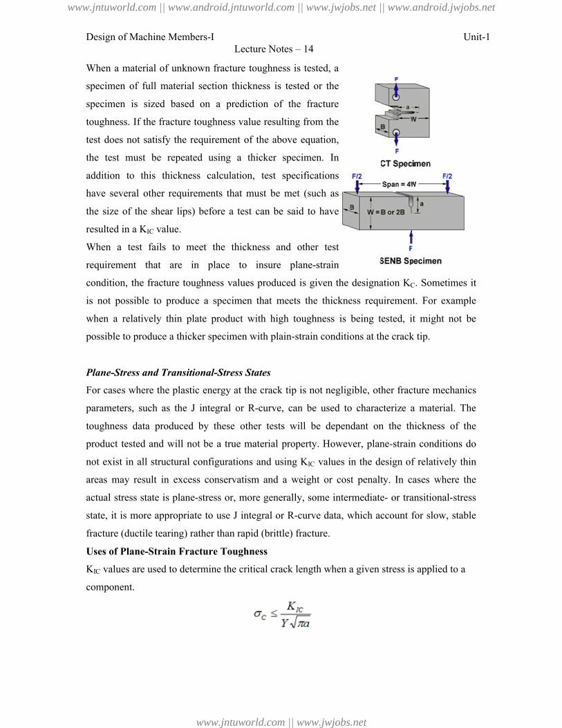
Design of Machine Members-I Unit-1Lecture Notes – 14
When a material of unknown fracture toughness is tested, a
specimen of full material section thickness is tested or the
specimen is sized based on a prediction of the fracture
toughness. If the fracture toughness value resulting from the
test does not satisfy the requirement of the above equation,
the test must be repeated using a thicker specimen. In
addition to this thickness calculation, test specifications
have several other requirements that must be met (such as
the size of the shear lips) before a test can be said to have
resulted in a KIC value.
When a test fails to meet the thickness and other test
requirement that are in place to insure plane-strain
condition, the fracture toughness values produced is given the designation KC. Sometimes it
is not possible to produce a specimen that meets the thickness requirement. For example
when a relatively thin plate product with high toughness is being tested, it might not be
possible to produce a thicker specimen with plain-strain conditions at the crack tip.
Plane-Stress and Transitional-Stress States
For cases where the plastic energy at the crack tip is not negligible, other fracture mechanics
parameters, such as the J integral or R-curve, can be used to characterize a material. The
toughness data produced by these other tests will be dependant on the thickness of the
product tested and will not be a true material property. However, plane-strain conditions do
not exist in all structural configurations and using KIC values in the design of relatively thin
areas may result in excess conservatism and a weight or cost penalty. In cases where the
actual stress state is plane-stress or, more generally, some intermediate- or transitional-stress
state, it is more appropriate to use J integral or R-curve data, which account for slow, stable
fracture (ductile tearing) rather than rapid (brittle) fracture.
Uses of Plane-Strain Fracture Toughness
KIC values are used to determine the critical crack length when a given stress is applied to a
component.
www.jntuworld.com || www.android.jntuworld.com || www.jwjobs.net || www.android.jwjobs.net
www.jntuworld.com || www.jwjobs.net
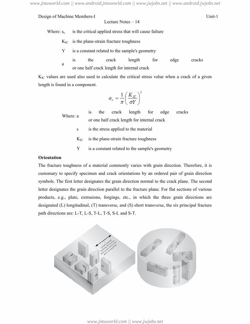
Design of Machine Members-I Unit-1Lecture Notes – 14
Where: sc is the critical applied stress that will cause failure
KIC is the plane-strain fracture toughness
Y is a constant related to the sample's geometry
ais the crack length for edge cracks
or one half crack length for internal crack
KIC values are used also used to calculate the critical stress value when a crack of a given
length is found in a component.
Where: ais the crack length for edge cracks
or one half crack length for internal crack
s is the stress applied to the material
KIC is the plane-strain fracture toughness
Y is a constant related to the sample's geometry
Orientation
The fracture toughness of a material commonly varies with grain direction. Therefore, it is
customary to specify specimen and crack orientations by an ordered pair of grain direction
symbols. The first letter designates the grain direction normal to the crack plane. The second
letter designates the grain direction parallel to the fracture plane. For flat sections of various
products, e.g., plate, extrusions, forgings, etc., in which the three grain directions are
designated (L) longitudinal, (T) transverse, and (S) short transverse, the six principal fracture
path directions are: L-T, L-S, T-L, T-S, S-L and S-T.
www.jntuworld.com || www.android.jntuworld.com || www.jwjobs.net || www.android.jwjobs.net
www.jntuworld.com || www.jwjobs.net
Design of Machine Members-I Unit-1Lecture Notes – 14
References:
1. Machine Design - V.Bandari .
2. Machine Design – R.S. Khurmi
3. Web sources.
www.jntuworld.com || www.android.jntuworld.com || www.jwjobs.net || www.android.jwjobs.net
www.jntuworld.com || www.jwjobs.net
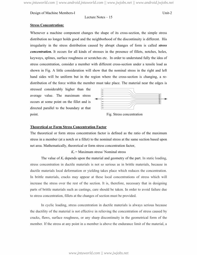
Design of Machine Members-I
Stress Concentration:
Whenever a machine component changes the shape of its cross
distribution no longer holds good and the neighborhood of the discontinuity is different. His
irregularity in the stress distribution caused by abrupt changes of form is called
concentration. It occurs for all kinds of stresses in the presence of fillets, notches, holes,
keyways, splines, surface roughness or scratches etc.
stress concentration, consider a member with different
shown in Fig. A little consideration will show that the
hand sides will be uniform but in the region
distribution of the force within the member must take place. The material
stressed considerably higher than the
average value. The maximum stress
occurs at some point on the fillet and is
directed parallel to the boundary at that
point.
Theoretical or Form Stress Concentration Factor
The theoretical or form stress concentration factor is defined as the ratio of the maximum
stress in a member (at a notch or a fillet)
net area. Mathematically, theoretical or form stress concentration factor,
Kt =
The value of Kt depends upon the material and geometry of the part.
stress concentration in ductile materials is not so serious as in brittle materials,
ductile materials local deformation or yielding takes place which reduces the concentration.
In brittle materials, cracks may appear at these local concentratio
increase the stress over the rest of
parts of brittle materials such as castings, care should be
to stress concentration, fillets at the
In cyclic loading, stress concentration in ductile materials is always serious because
the ductility of the material is not effective in relieving the concentration of stress caused by
cracks, flaws, surface roughness,
member. If the stress at any point in a member is above the
Lecture Notes – 15
Whenever a machine component changes the shape of its cross-section, the simple stress
distribution no longer holds good and the neighborhood of the discontinuity is different. His
irregularity in the stress distribution caused by abrupt changes of form is called
It occurs for all kinds of stresses in the presence of fillets, notches, holes,
roughness or scratches etc. In order to understand fully the idea of
concentration, consider a member with different cross-section under a tensile load as
Fig. A little consideration will show that the nominal stress in the right and left
be uniform but in the region where the cross-section is changing, a re
within the member must take place. The material near the edges is
stressed considerably higher than the
average value. The maximum stress
some point on the fillet and is
parallel to the boundary at that
Fig. Stress concentration
Theoretical or Form Stress Concentration Factor
The theoretical or form stress concentration factor is defined as the ratio of the maximum
in a member (at a notch or a fillet) to the nominal stress at the same section based upon
Mathematically, theoretical or form stress concentration factor,
Maximum stress/ Nominal stress
depends upon the material and geometry of the part. In static loading,
stress concentration in ductile materials is not so serious as in brittle materials,
ductile materials local deformation or yielding takes place which reduces the concentration.
materials, cracks may appear at these local concentrations of stress which will
increase the stress over the rest of the section. It is, therefore, necessary that in designing
parts of brittle materials such as castings, care should be taken. In order to avoid failure due
to stress concentration, fillets at the changes of section must be provided.
In cyclic loading, stress concentration in ductile materials is always serious because
material is not effective in relieving the concentration of stress caused by
cracks, flaws, surface roughness, or any sharp discontinuity in the geometrical form of the
member. If the stress at any point in a member is above the endurance limit of the material, a
Unit-2
section, the simple stress
distribution no longer holds good and the neighborhood of the discontinuity is different. His
irregularity in the stress distribution caused by abrupt changes of form is called stress
It occurs for all kinds of stresses in the presence of fillets, notches, holes,
rstand fully the idea of
section under a tensile load as
nominal stress in the right and left
is changing, a re-
near the edges is
The theoretical or form stress concentration factor is defined as the ratio of the maximum
to the nominal stress at the same section based upon
In static loading,
stress concentration in ductile materials is not so serious as in brittle materials, because in
ductile materials local deformation or yielding takes place which reduces the concentration.
ns of stress which will
the section. It is, therefore, necessary that in designing
taken. In order to avoid failure due
In cyclic loading, stress concentration in ductile materials is always serious because
material is not effective in relieving the concentration of stress caused by
any sharp discontinuity in the geometrical form of the
endurance limit of the material, a
www.jntuworld.com || www.android.jntuworld.com || www.jwjobs.net || www.android.jwjobs.net
www.jntuworld.com || www.jwjobs.net
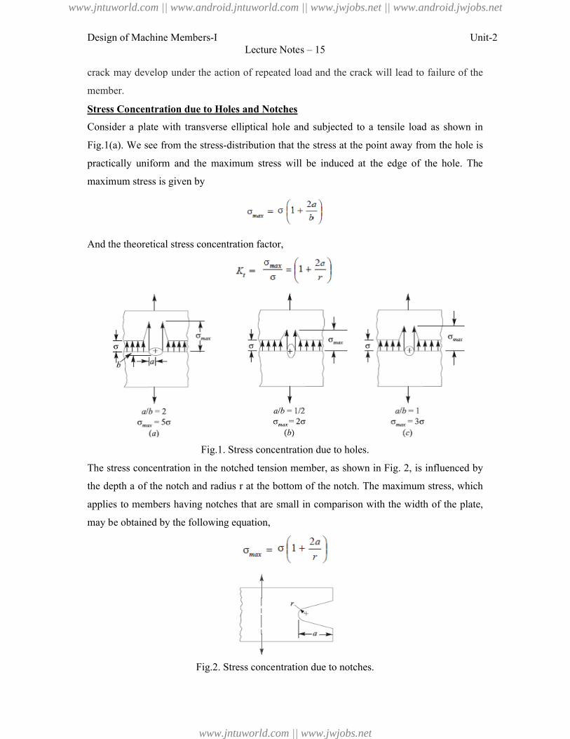
Design of Machine Members-I
crack may develop under the action of repeated load and the crack will lead to
member.
Stress Concentration due to Holes and Notches
Consider a plate with transverse elliptical hole and subjecte
Fig.1(a). We see from the stress-
practically uniform and the maximum stress will be induced at the edge of the hole. The
maximum stress is given by
And the theoretical stress concentration factor,
Fig.1. Stress concentration due to holes.
The stress concentration in the notched tension member, as
the depth a of the notch and radius
applies to members having notches that are small in comparison with the width
may be obtained by the following equation,
Fig.2. Stress concentration due to notches.
Lecture Notes – 15
crack may develop under the action of repeated load and the crack will lead to
Stress Concentration due to Holes and Notches
Consider a plate with transverse elliptical hole and subjected to a tensile load as shown in
-distribution that the stress at the point away from the hole is
and the maximum stress will be induced at the edge of the hole. The
And the theoretical stress concentration factor,
. Stress concentration due to holes.
The stress concentration in the notched tension member, as shown in Fig. 2, is influenced by
of the notch and radius r at the bottom of the notch. The maximum stress, which
members having notches that are small in comparison with the width
may be obtained by the following equation,
. Stress concentration due to notches.
Unit-2
failure of the
d to a tensile load as shown in
distribution that the stress at the point away from the hole is
and the maximum stress will be induced at the edge of the hole. The
, is influenced by
at the bottom of the notch. The maximum stress, which
members having notches that are small in comparison with the width of the plate,
www.jntuworld.com || www.android.jntuworld.com || www.jwjobs.net || www.android.jwjobs.net
www.jntuworld.com || www.jwjobs.net
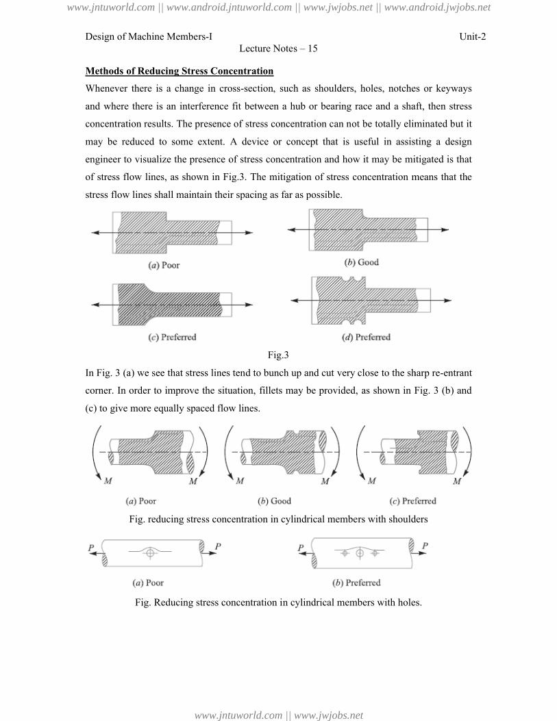
Design of Machine Members-I
Methods of Reducing Stress Concentration
Whenever there is a change in cross
and where there is an interference
concentration results. The presence of
may be reduced to some extent. A device or
engineer to visualize the presence of stress concent
of stress flow lines, as shown in Fig.3
stress flow lines shall maintain their spacing as far as possible.
In Fig. 3 (a) we see that stress lines tend
corner. In order to improve the situation, fillets may be provided, as shown in Fig.
(c) to give more equally spaced flow lines.
Fig. reducing stress concentration in cylindrical members w
Fig. Reducing stress concentration in cylindrical members with holes.
Lecture Notes – 15
Methods of Reducing Stress Concentration
change in cross-section, such as shoulders, holes, notches or keyways
and where there is an interference fit between a hub or bearing race and a shaft, then stress
concentration results. The presence of stress concentration can not be totally eliminated but it
may be reduced to some extent. A device or concept that is useful in assisting a design
engineer to visualize the presence of stress concentration and how it may be mitigated is that
flow lines, as shown in Fig.3. The mitigation of stress concentration means that the
stress flow lines shall maintain their spacing as far as possible.
Fig.3
) we see that stress lines tend to bunch up and cut very close to the sharp re
corner. In order to improve the situation, fillets may be provided, as shown in Fig.
give more equally spaced flow lines.
Fig. reducing stress concentration in cylindrical members with shoulders
educing stress concentration in cylindrical members with holes.
Unit-2
section, such as shoulders, holes, notches or keyways
shaft, then stress
stress concentration can not be totally eliminated but it
concept that is useful in assisting a design
ration and how it may be mitigated is that
concentration means that the
to bunch up and cut very close to the sharp re-entrant
corner. In order to improve the situation, fillets may be provided, as shown in Fig. 3 (b) and
ith shoulders
educing stress concentration in cylindrical members with holes.
www.jntuworld.com || www.android.jntuworld.com || www.jwjobs.net || www.android.jwjobs.net
www.jntuworld.com || www.jwjobs.net
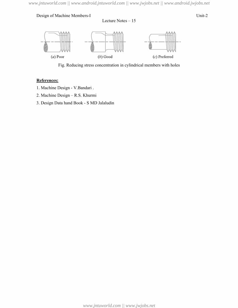
Design of Machine Members-I
Fig. Reducing stress concentration in cylindrical members with holes
References:
1. Machine Design - V.Bandari .
2. Machine Design – R.S. Khurmi
3. Design Data hand Book - S MD Jalaludin
Lecture Notes – 15
educing stress concentration in cylindrical members with holes
V.Bandari .
R.S. Khurmi
S MD Jalaludin
Unit-2
educing stress concentration in cylindrical members with holes
www.jntuworld.com || www.android.jntuworld.com || www.jwjobs.net || www.android.jwjobs.net
www.jntuworld.com || www.jwjobs.net
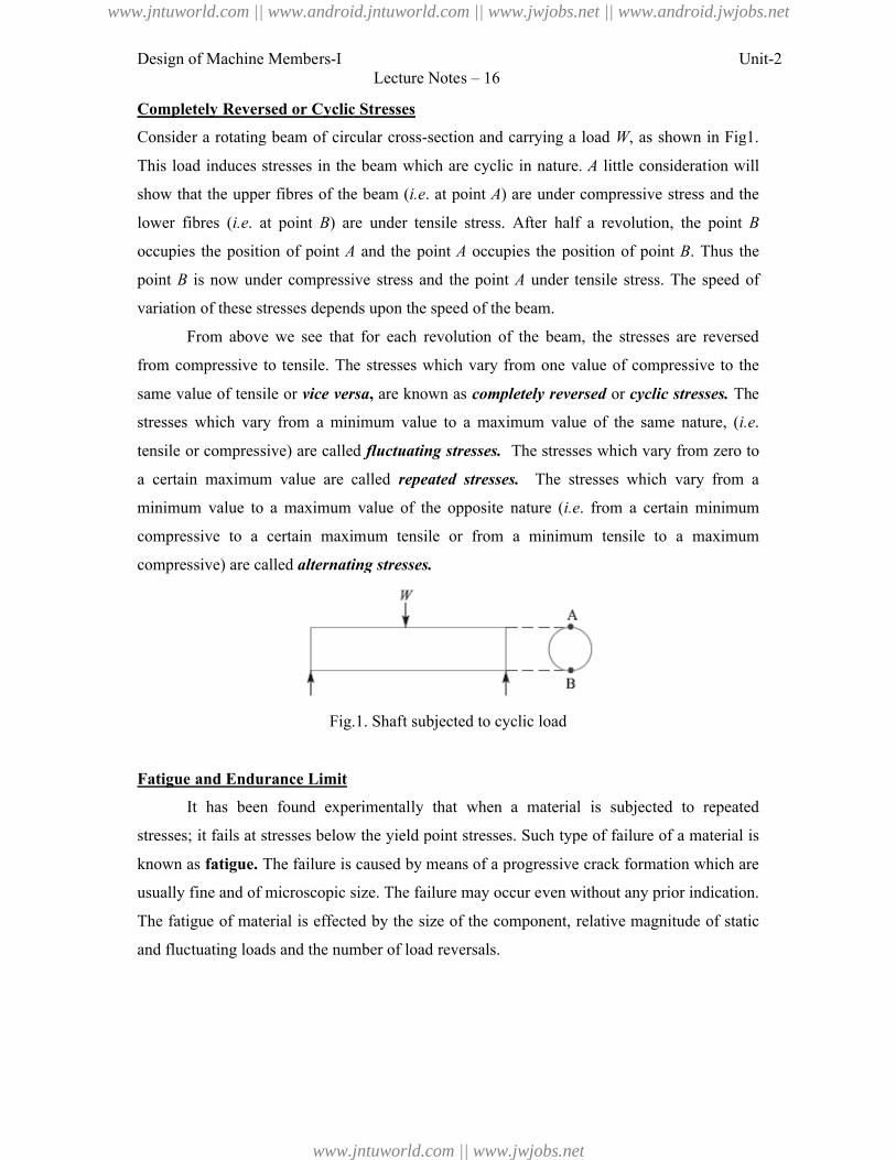
Design of Machine Members-I
Completely Reversed or Cyclic Stresses
Consider a rotating beam of circular cross
This load induces stresses in the beam which are cyclic in nature.
show that the upper fibres of the
lower fibres (i.e. at point B) are under tensile stress. After
occupies the position of point A
point B is now under compressive stress and
variation of these stresses depends upon the speed of the beam.
From above we see that for each revolution of the
from compressive to tensile. The stresses which vary from one value of compressive to
same value of tensile or vice versa
stresses which vary from a minimum value to a maximum value of the same nature, (
tensile or compressive) are called
a certain maximum value are called
minimum value to a maximum value of the opposite nature (
compressive to a certain maximum tensile or from a minimum tensile to a maximum
compressive) are called alternating stresses.
Fig.1. Shaft subjected to cyclic load
Fatigue and Endurance Limit
It has been found experimentally that when a material is
stresses; it fails at stresses below the yield point stresses. Such type of failure of a material is
known as fatigue. The failure is caused by means of a progressive crack formation which are
usually fine and of microscopic size. The
The fatigue of material is effected by
and fluctuating loads and the number of load
Lecture Notes – 16
Completely Reversed or Cyclic Stresses
Consider a rotating beam of circular cross-section and carrying a load W, as shown in Fig
induces stresses in the beam which are cyclic in nature. A little consideration will
the beam (i.e. at point A) are under compressive stress and the
) are under tensile stress. After half a revolution, the point
A and the point A occupies the position of point
is now under compressive stress and the point A under tensile stress. The speed of
of these stresses depends upon the speed of the beam.
From above we see that for each revolution of the beam, the stresses are reversed
The stresses which vary from one value of compressive to
vice versa, are known as completely reversed or cyclic stresses.
stresses which vary from a minimum value to a maximum value of the same nature, (
compressive) are called fluctuating stresses. The stresses which vary from zero to
a certain maximum value are called repeated stresses. The stresses which vary from a
minimum value to a maximum value of the opposite nature (i.e. from a certain minimum
compressive to a certain maximum tensile or from a minimum tensile to a maximum
alternating stresses.
Fig.1. Shaft subjected to cyclic load
It has been found experimentally that when a material is subjected to repeated
stresses below the yield point stresses. Such type of failure of a material is
failure is caused by means of a progressive crack formation which are
size. The failure may occur even without any prior indication.
The fatigue of material is effected by the size of the component, relative magnitude of static
and fluctuating loads and the number of load reversals.
Unit-2
, as shown in Fig1.
little consideration will
) are under compressive stress and the
half a revolution, the point B
occupies the position of point B. Thus the
under tensile stress. The speed of
beam, the stresses are reversed
The stresses which vary from one value of compressive to the
cyclic stresses. The
stresses which vary from a minimum value to a maximum value of the same nature, (i.e.
The stresses which vary from zero to
The stresses which vary from a
certain minimum
compressive to a certain maximum tensile or from a minimum tensile to a maximum
subjected to repeated
stresses below the yield point stresses. Such type of failure of a material is
failure is caused by means of a progressive crack formation which are
failure may occur even without any prior indication.
the size of the component, relative magnitude of static
www.jntuworld.com || www.android.jntuworld.com || www.jwjobs.net || www.android.jwjobs.net
www.jntuworld.com || www.jwjobs.net
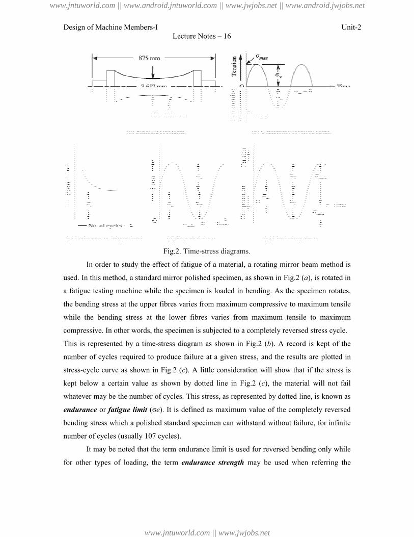
Design of Machine Members-I
In order to study the effect of fatigue of a material, a rotating mirror beam method is
used. In this method, a standard mirror polished specimen
a fatigue testing machine while the specimen is loaded
the bending stress at the upper fibres varies from
while the bending stress at the lower fibres
compressive. In other words, the specimen is
This is represented by a time-stress diagram
number of cycles required to produce
stress-cycle curve as shown in Fig.
kept below a certain value as shown
whatever may be the number of cycles. This
endurance or fatigue limit (σe). It is defined as
bending stress which a polished standard specimen can
number of cycles (usually 107 cycles).
It may be noted that the term endurance limit is used for re
for other types of loading, the term
Lecture Notes – 16
Fig.2. Time-stress diagrams.
e effect of fatigue of a material, a rotating mirror beam method is
this method, a standard mirror polished specimen, as shown in Fig.2 (a), is rotated in
a fatigue testing machine while the specimen is loaded in bending. As the specimen rotates,
bending stress at the upper fibres varies from maximum compressive to maximum tensile
while the bending stress at the lower fibres varies from maximum tensile to maximum
compressive. In other words, the specimen is subjected to a completely reversed
stress diagram as shown in Fig.2 (b). A record is kept of
number of cycles required to produce failure at a given stress, and the results are
cycle curve as shown in Fig.2 (c). A little consideration will show that if
kept below a certain value as shown by dotted line in Fig.2 (c), the material will not fail
whatever may be the number of cycles. This stress, as represented by dotted line, is known as
). It is defined as maximum value of the completely reversed
bending stress which a polished standard specimen can withstand without failure, for infinite
number of cycles (usually 107 cycles).
It may be noted that the term endurance limit is used for reversed bending only while
types of loading, the term endurance strength may be used when referring the
Unit-2
e effect of fatigue of a material, a rotating mirror beam method is
), is rotated in
in bending. As the specimen rotates,
maximum compressive to maximum tensile
varies from maximum tensile to maximum
subjected to a completely reversed stress cycle.
). A record is kept of the
failure at a given stress, and the results are plotted in
ideration will show that if the stress is
), the material will not fail
stress, as represented by dotted line, is known as
maximum value of the completely reversed
withstand without failure, for infinite
versed bending only while
may be used when referring the
www.jntuworld.com || www.android.jntuworld.com || www.jwjobs.net || www.android.jwjobs.net
www.jntuworld.com || www.jwjobs.net
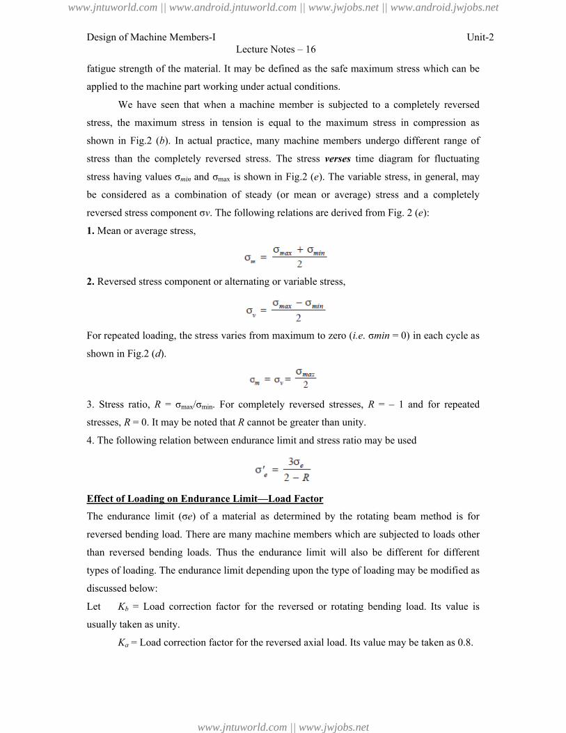
Design of Machine Members-I Unit-2Lecture Notes – 16
fatigue strength of the material. It may be defined as the safe maximum stress which can be
applied to the machine part working under actual conditions.
We have seen that when a machine member is subjected to a completely reversed
stress, the maximum stress in tension is equal to the maximum stress in compression as
shown in Fig.2 (b). In actual practice, many machine members undergo different range of
stress than the completely reversed stress. The stress verses time diagram for fluctuating
stress having values σmin and σmax is shown in Fig.2 (e). The variable stress, in general, may
be considered as a combination of steady (or mean or average) stress and a completely
reversed stress component σv. The following relations are derived from Fig. 2 (e):
1. Mean or average stress,
2. Reversed stress component or alternating or variable stress,
For repeated loading, the stress varies from maximum to zero (i.e. σmin = 0) in each cycle as
shown in Fig.2 (d).
3. Stress ratio, R = σmax/σmin. For completely reversed stresses, R = – 1 and for repeated
stresses, R = 0. It may be noted that R cannot be greater than unity.
4. The following relation between endurance limit and stress ratio may be used
Effect of Loading on Endurance Limit—Load Factor
The endurance limit (σe) of a material as determined by the rotating beam method is for
reversed bending load. There are many machine members which are subjected to loads other
than reversed bending loads. Thus the endurance limit will also be different for different
types of loading. The endurance limit depending upon the type of loading may be modified as
discussed below:
Let Kb = Load correction factor for the reversed or rotating bending load. Its value is
usually taken as unity.
Ka = Load correction factor for the reversed axial load. Its value may be taken as 0.8.
www.jntuworld.com || www.android.jntuworld.com || www.jwjobs.net || www.android.jwjobs.net
www.jntuworld.com || www.jwjobs.net
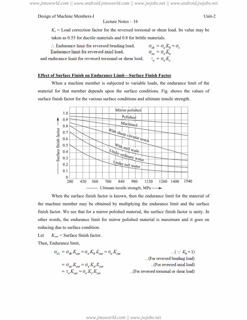
Design of Machine Members-I
Ks = Load correction factor for the
taken as 0.55 for ductile materials and 0.8 for brittle
Effect of Surface Finish on Endurance Limit
When a machine member is subjected to variable loads, the endurance limit of the
material for that member depends upo
surface finish factor for the various surface conditions and ultimate tensile strength.
When the surface finish factor is known, then the endurance limit for the material of
the machine member may be obta
finish factor. We see that for a mirror polished material, the surface finish factor is unity. In
other words, the endurance limit for
reducing due to surface condition.
Let Ksur = Surface finish factor.
Then, Endurance limit,
Lecture Notes – 16
= Load correction factor for the reversed torsional or shear load. Its
ductile materials and 0.8 for brittle materials.
Effect of Surface Finish on Endurance Limit—Surface Finish Factor
When a machine member is subjected to variable loads, the endurance limit of the
that member depends upon the surface conditions. Fig. shows the values of
for the various surface conditions and ultimate tensile strength.
When the surface finish factor is known, then the endurance limit for the material of
member may be obtained by multiplying the endurance limit and the surface
finish factor. We see that for a mirror polished material, the surface finish factor is unity. In
other words, the endurance limit for mirror polished material is maximum and it goes on
o surface condition.
= Surface finish factor.
Unit-2
value may be
When a machine member is subjected to variable loads, the endurance limit of the
shows the values of
for the various surface conditions and ultimate tensile strength.
When the surface finish factor is known, then the endurance limit for the material of
ined by multiplying the endurance limit and the surface
finish factor. We see that for a mirror polished material, the surface finish factor is unity. In
mirror polished material is maximum and it goes on
www.jntuworld.com || www.android.jntuworld.com || www.jwjobs.net || www.android.jwjobs.net
www.jntuworld.com || www.jwjobs.net
Design of Machine Members-I Unit-2Lecture Notes – 16
Effect of Size on Endurance Limit—Size Factor
A little consideration will show that if the size of the standard specimen as shown in Fig.2 (a)
is increased, then the endurance limit of the material will decrease. This is due to the fact that
a longer specimen will have more defects than a smaller one.
Let Ksz = Size factor.
Then, Endurance limit,
The value of size factor is taken as unity for the standard specimen having nominal diameter
of 7.657 mm. When the nominal diameter of the specimen is more than 7.657 mm but less
than 50 mm, the value of size factor may be taken as 0.85. When the nominal diameter of the
specimen is more than 50 mm, then the value of size factor may be taken as 0.75.
Effect of Miscellaneous Factors on Endurance Limit
In addition to the surface finish factor (Ksur), size factor (Ksz) and load factors Kb, Ka and Ks,
there are many other factors such as reliability factor (Kr), temperature factor (Kt), impact
factor (Ki) etc. which has effect on the endurance limit of a material. Considering all these
factors, the endurance limit may be determined by using the following expressions:
1. For the reversed bending load, endurance limit,
2. For the reversed axial load, endurance limit,
3. For the reversed torsional or shear load, endurance limit,
In solving problems, if the value of any of the above factors is not known, it may be taken as
unity.
Relation between Endurance Limit and Ultimate Tensile Strength
It has been found experimentally that endurance limit (σe) of a material subjected to
fatigue loading is a function of ultimate tensile strength (σu).
www.jntuworld.com || www.android.jntuworld.com || www.jwjobs.net || www.android.jwjobs.net
www.jntuworld.com || www.jwjobs.net
Design of Machine Members-I Unit-2Lecture Notes – 16
Factor of Safety for Fatigue Loading
When a component is subjected to fatigue loading, the endurance limit is the criterion for
failure. Therefore, the factor of safety should be based on endurance limit. Mathematically,
Fatigue Stress Concentration Factor
When a machine member is subjected to cyclic or fatigue loading, the value of fatigue stress
concentration factor shall be applied instead of theoretical stress concentration factor. Since
the determination of fatigue stress concentration factor is not an easy task, therefore from
experimental tests it is defined as
Fatigue stress concentration factor,
Notch Sensitivity
In cyclic loading, the effect of the notch or the fillet is usually less than predicted by the use
of the theoretical factors as discussed before. The difference depends upon the stress gradient
in the region of the stress concentration and on the hardness of the material. The term notch
sensitivity is applied to this behaviour. It may be defined as the degree to which the
theoretical effect of stress concentration is actually reached. The stress gradient depends
mainly on the radius of the notch, hole or fillet and on the grain size of the material. Since the
extensive data for estimating the notch sensitivity factor (q) is not available, therefore the
curves, as shown in Fig., may be used for determining the values of q for two steals. When
the notch sensitivity factor q is used in cyclic loading, then fatigue stress concentration factor
may be obtained from the following relations:
Or
www.jntuworld.com || www.android.jntuworld.com || www.jwjobs.net || www.android.jwjobs.net
www.jntuworld.com || www.jwjobs.net
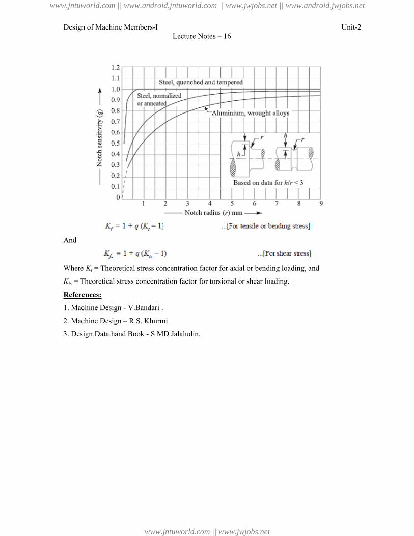
Design of Machine Members-I
And
Where Kt = Theoretical stress concentration factor for
Kts = Theoretical stress concentration factor for torsional or shear
References:
1. Machine Design - V.Bandari .
2. Machine Design – R.S. Khurmi
3. Design Data hand Book - S MD Jalaludin
Lecture Notes – 16
= Theoretical stress concentration factor for axial or bending loading, and
= Theoretical stress concentration factor for torsional or shear loading.
V.Bandari .
R.S. Khurmi
S MD Jalaludin.
Unit-2
loading, and
www.jntuworld.com || www.android.jntuworld.com || www.jwjobs.net || www.android.jwjobs.net
www.jntuworld.com || www.jwjobs.net
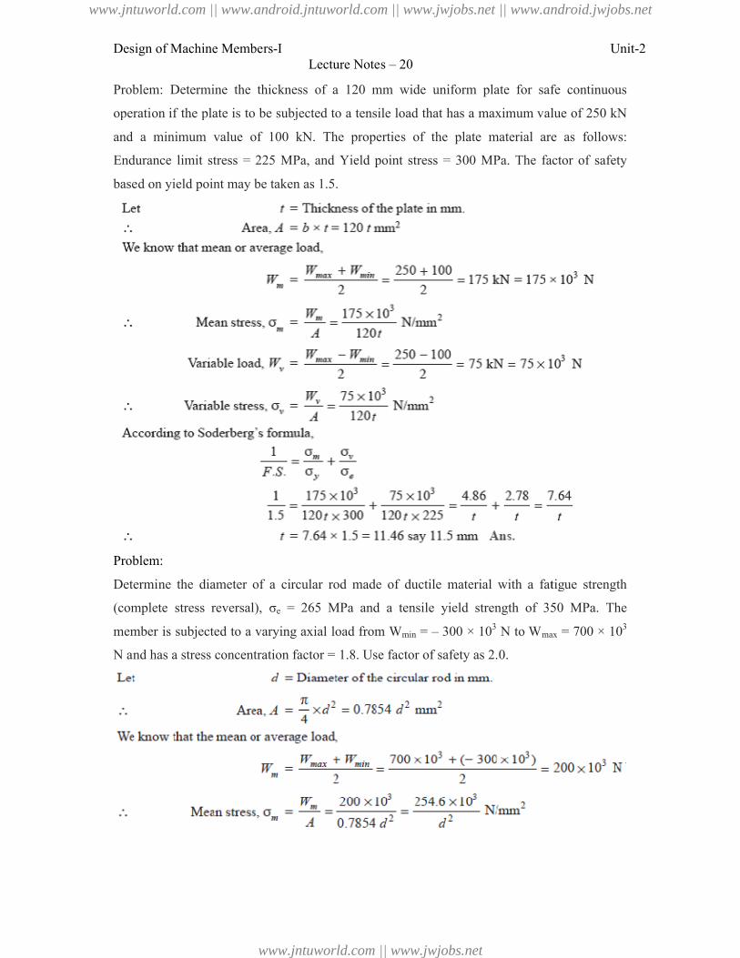
Design of Machine Members-I
Problem: Determine the thickness of a 120 mm wide uniform plate for safe continuous
operation if the plate is to be subjected to a tensile load that has a maximum value of 250 kN
and a minimum value of 100 kN. The properties of the plate material are as
Endurance limit stress = 225 MPa, and Yield point stress = 300 MPa. The factor of safety
based on yield point may be taken as 1.5.
Problem:
Determine the diameter of a circular rod made of ductile material with a fatigue
(complete stress reversal), σe = 265 MPa and a tensile yield strength of 350 MPa. The
member is subjected to a varying axial load from W
N and has a stress concentration factor = 1.8. Use factor of safety as 2.0.
Lecture Notes – 20
Problem: Determine the thickness of a 120 mm wide uniform plate for safe continuous
operation if the plate is to be subjected to a tensile load that has a maximum value of 250 kN
and a minimum value of 100 kN. The properties of the plate material are as
Endurance limit stress = 225 MPa, and Yield point stress = 300 MPa. The factor of safety
based on yield point may be taken as 1.5.
Determine the diameter of a circular rod made of ductile material with a fatigue
= 265 MPa and a tensile yield strength of 350 MPa. The
member is subjected to a varying axial load from Wmin = – 300 × 103 N to Wmax
has a stress concentration factor = 1.8. Use factor of safety as 2.0.
Unit-2
Problem: Determine the thickness of a 120 mm wide uniform plate for safe continuous
operation if the plate is to be subjected to a tensile load that has a maximum value of 250 kN
and a minimum value of 100 kN. The properties of the plate material are as follows:
Endurance limit stress = 225 MPa, and Yield point stress = 300 MPa. The factor of safety
Determine the diameter of a circular rod made of ductile material with a fatigue strength
= 265 MPa and a tensile yield strength of 350 MPa. The
max = 700 × 103
www.jntuworld.com || www.android.jntuworld.com || www.jwjobs.net || www.android.jwjobs.net
www.jntuworld.com || www.jwjobs.net
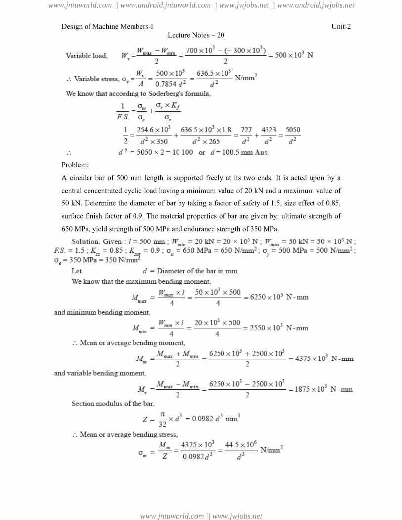
Design of Machine Members-I
Problem:
A circular bar of 500 mm length is supported freely at its two ends. It is acted
central concentrated cyclic load having a minimum value of 20 kN and a maximum value
50 kN. Determine the diameter of bar by taking a factor of safety of 1.5, size
surface finish factor of 0.9. The material properties of bar are given by: ultimate strength of
650 MPa, yield strength of 500 MPa and endurance strength of 350 MPa.
Lecture Notes – 20
circular bar of 500 mm length is supported freely at its two ends. It is acted
central concentrated cyclic load having a minimum value of 20 kN and a maximum value
50 kN. Determine the diameter of bar by taking a factor of safety of 1.5, size effect of 0.85,
finish factor of 0.9. The material properties of bar are given by: ultimate strength of
strength of 500 MPa and endurance strength of 350 MPa.
Unit-2
circular bar of 500 mm length is supported freely at its two ends. It is acted upon by a
central concentrated cyclic load having a minimum value of 20 kN and a maximum value of
effect of 0.85,
finish factor of 0.9. The material properties of bar are given by: ultimate strength of
www.jntuworld.com || www.android.jntuworld.com || www.jwjobs.net || www.android.jwjobs.net
www.jntuworld.com || www.jwjobs.net
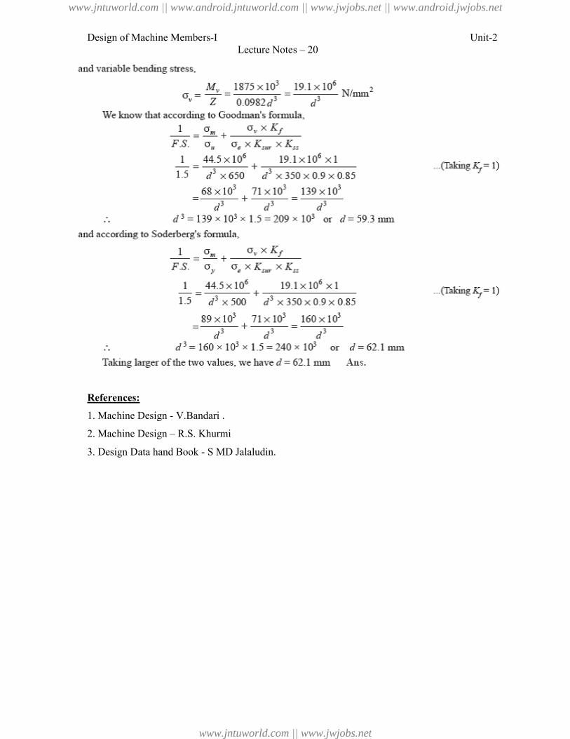
Design of Machine Members-I
References:
1. Machine Design - V.Bandari .
2. Machine Design – R.S. Khurmi
3. Design Data hand Book - S MD Jalaludin.
Lecture Notes – 20
V.Bandari .
. Khurmi
S MD Jalaludin.
Unit-2
www.jntuworld.com || www.android.jntuworld.com || www.jwjobs.net || www.android.jwjobs.net
www.jntuworld.com || www.jwjobs.net

Design of Machine Members-I Unit-2Lecture Notes – 20
www.jntuworld.com || www.android.jntuworld.com || www.jwjobs.net || www.android.jwjobs.net
www.jntuworld.com || www.jwjobs.net
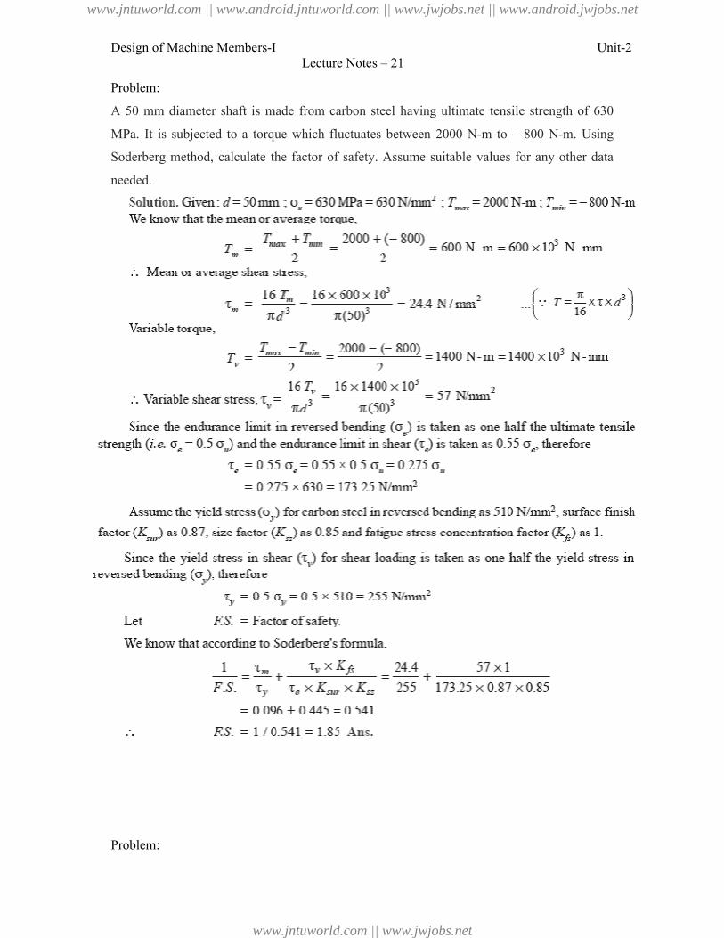
Design of Machine Members-I
Problem:
A 50 mm diameter shaft is made from carbon steel having ultimate tensile
MPa. It is subjected to a torque which fluctuates between 2000 N
Soderberg method, calculate the factor of safety. Assume suitable
needed.
Problem:
Lecture Notes – 21
A 50 mm diameter shaft is made from carbon steel having ultimate tensile strength of 630
MPa. It is subjected to a torque which fluctuates between 2000 N-m to – 800 N
Soderberg method, calculate the factor of safety. Assume suitable values for any other data
Unit-2
strength of 630
800 N-m. Using
values for any other data
www.jntuworld.com || www.android.jntuworld.com || www.jwjobs.net || www.android.jwjobs.net
www.jntuworld.com || www.jwjobs.net
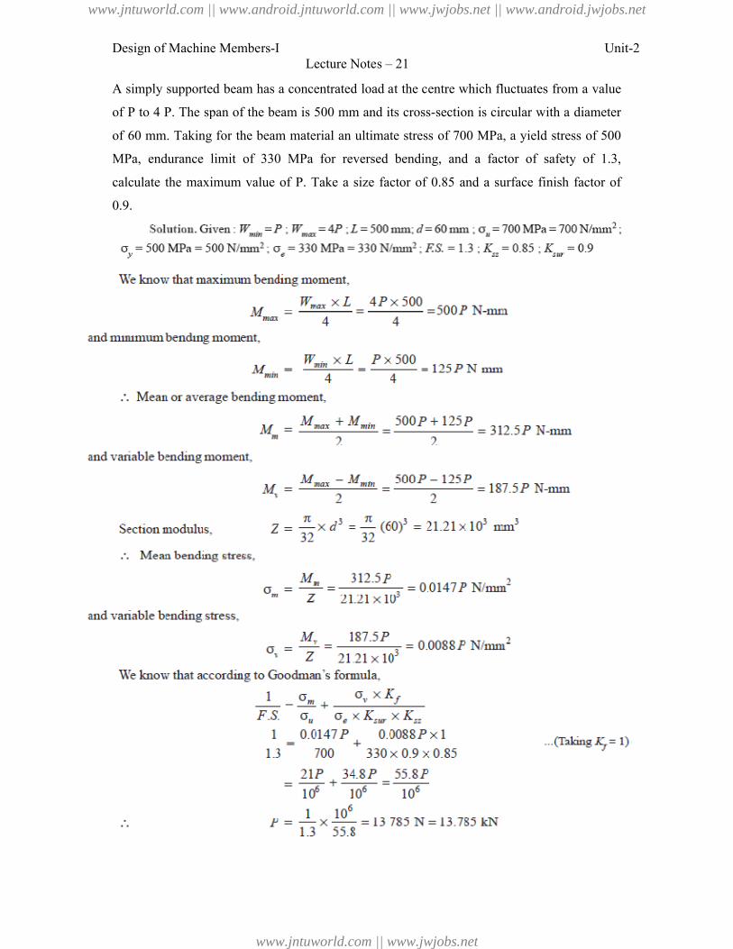
Design of Machine Members-I
A simply supported beam has a concentrated load at the centre which fluctuates
of P to 4 P. The span of the beam is 500 mm and its cross
of 60 mm. Taking for the beam material an ultimate stress of 700 MPa, a yield stress of 500
MPa, endurance limit of 330 MPa for reversed bending, and a factor of safety of 1.3,
calculate the maximum value of P. Take a size factor of 0.85 and a surface finish factor of
0.9.
Lecture Notes – 21
A simply supported beam has a concentrated load at the centre which fluctuates
of P to 4 P. The span of the beam is 500 mm and its cross-section is circular with a
or the beam material an ultimate stress of 700 MPa, a yield stress of 500
MPa, endurance limit of 330 MPa for reversed bending, and a factor of safety of 1.3,
maximum value of P. Take a size factor of 0.85 and a surface finish factor of
Unit-2
A simply supported beam has a concentrated load at the centre which fluctuates from a value
section is circular with a diameter
or the beam material an ultimate stress of 700 MPa, a yield stress of 500
MPa, endurance limit of 330 MPa for reversed bending, and a factor of safety of 1.3,
maximum value of P. Take a size factor of 0.85 and a surface finish factor of
www.jntuworld.com || www.android.jntuworld.com || www.jwjobs.net || www.android.jwjobs.net
www.jntuworld.com || www.jwjobs.net
Design of Machine Members-I
References:
1. Machine Design - V.Bandari .
2. Machine Design – R.S. Khurmi
3. Design Data hand Book - S MD Jalaludin.
Lecture Notes – 21
V.Bandari .
R.S. Khurmi
S MD Jalaludin.
Unit-2
www.jntuworld.com || www.android.jntuworld.com || www.jwjobs.net || www.android.jwjobs.net
www.jntuworld.com || www.jwjobs.net
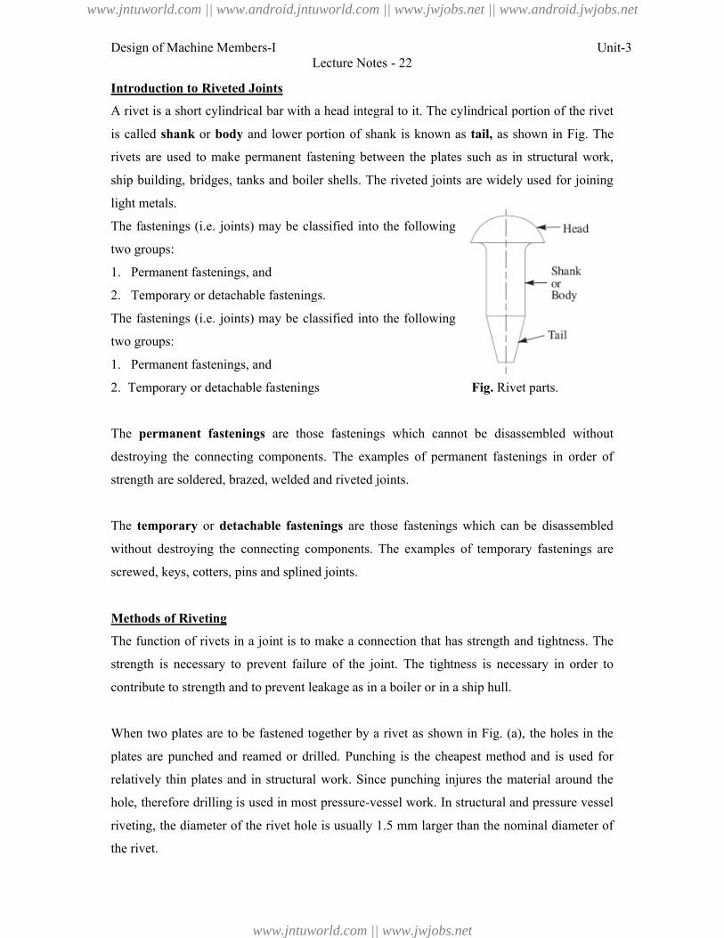
Design of Machine Members-I
Introduction to Riveted Joints
A rivet is a short cylindrical bar with a head integral to it. The cylindrical portion of the rivet
is called shank or body and lower portion of shank is known as
rivets are used to make permanent fastening between the plates such as in structural work,
ship building, bridges, tanks and boiler shells. The riveted joints are widely used for joining
light metals.
The fastenings (i.e. joints) may be classified int
two groups:
1. Permanent fastenings, and
2. Temporary or detachable fastenings.
The fastenings (i.e. joints) may be classified into the following
two groups:
1. Permanent fastenings, and
2. Temporary or detachable fastenings
The permanent fastenings are those fastenings which
destroying the connecting components. The examples of permanent fastenings in order of
strength are soldered, brazed, welded and riveted joints.
The temporary or detachable
without destroying the connecting components. The examples of temporary fastenings are
screwed, keys, cotters, pins and splined joints.
Methods of Riveting
The function of rivets in a joint is to m
strength is necessary to prevent failure of the joint. The tightness is necessary in order to
contribute to strength and to prevent leakage as in a boiler or in a ship hull.
When two plates are to be fastened together by a rivet as shown i
plates are punched and reamed or drilled. Punching is the cheapest method and is used for
relatively thin plates and in structural work. Since punching injures the material around the
hole, therefore drilling is used in most pressure
riveting, the diameter of the rivet hole is usually 1.5 mm larger than the nominal diameter of
the rivet.
Lecture Notes - 22
A rivet is a short cylindrical bar with a head integral to it. The cylindrical portion of the rivet
and lower portion of shank is known as tail, as shown in Fig.
rivets are used to make permanent fastening between the plates such as in structural work,
ship building, bridges, tanks and boiler shells. The riveted joints are widely used for joining
joints) may be classified into the following
Temporary or detachable fastenings.
joints) may be classified into the following
Temporary or detachable fastenings Fig. Rivet parts.
are those fastenings which cannot be disassembled without
destroying the connecting components. The examples of permanent fastenings in order of
strength are soldered, brazed, welded and riveted joints.
detachable fastenings are those fastenings which can be disassembled
without destroying the connecting components. The examples of temporary fastenings are
screwed, keys, cotters, pins and splined joints.
The function of rivets in a joint is to make a connection that has strength and tightness. The
strength is necessary to prevent failure of the joint. The tightness is necessary in order to
contribute to strength and to prevent leakage as in a boiler or in a ship hull.
astened together by a rivet as shown in Fig. (a), the holes in the
plates are punched and reamed or drilled. Punching is the cheapest method and is used for
relatively thin plates and in structural work. Since punching injures the material around the
therefore drilling is used in most pressure-vessel work. In structural and pressure vessel
riveting, the diameter of the rivet hole is usually 1.5 mm larger than the nominal diameter of
Unit-3
A rivet is a short cylindrical bar with a head integral to it. The cylindrical portion of the rivet
as shown in Fig. The
rivets are used to make permanent fastening between the plates such as in structural work,
ship building, bridges, tanks and boiler shells. The riveted joints are widely used for joining
Rivet parts.
cannot be disassembled without
destroying the connecting components. The examples of permanent fastenings in order of
are those fastenings which can be disassembled
without destroying the connecting components. The examples of temporary fastenings are
ake a connection that has strength and tightness. The
strength is necessary to prevent failure of the joint. The tightness is necessary in order to
), the holes in the
plates are punched and reamed or drilled. Punching is the cheapest method and is used for
relatively thin plates and in structural work. Since punching injures the material around the
vessel work. In structural and pressure vessel
riveting, the diameter of the rivet hole is usually 1.5 mm larger than the nominal diameter of
www.jntuworld.com || www.android.jntuworld.com || www.jwjobs.net || www.android.jwjobs.net
www.jntuworld.com || www.jwjobs.net
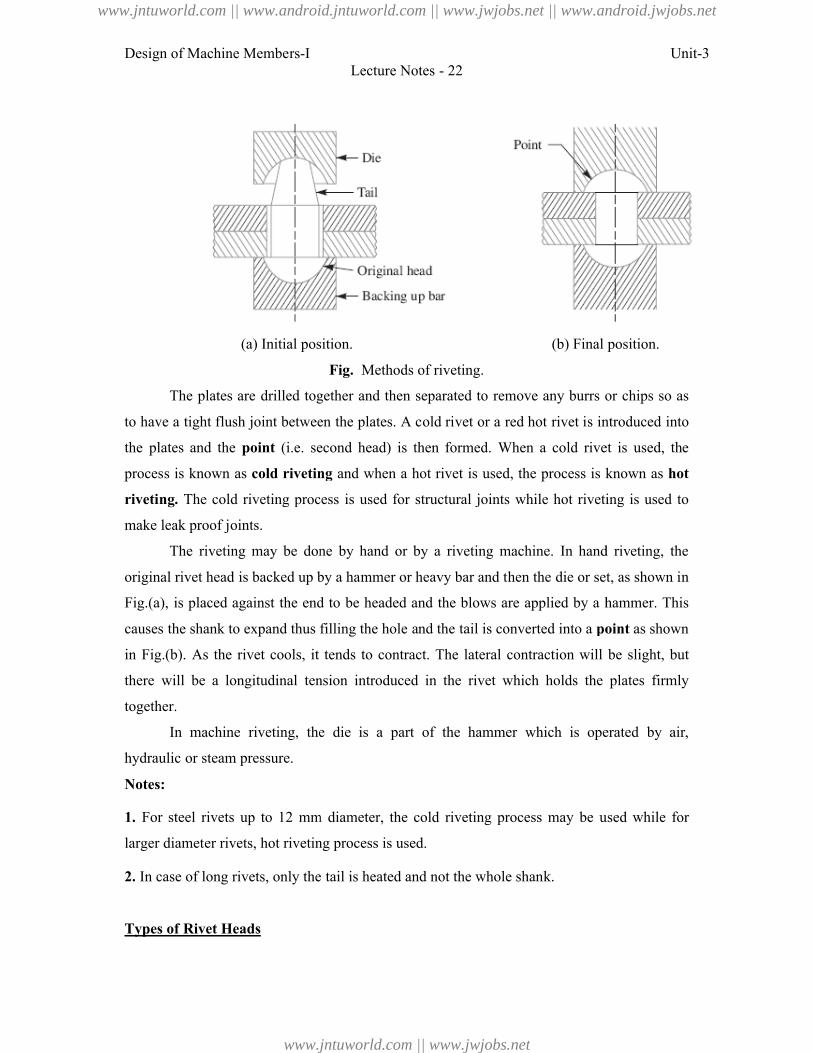
Design of Machine Members-I
(a) Initial position.
The plates are drilled together and then separated to remove any burrs or chips so as
to have a tight flush joint between the plates. A cold rivet or a red hot
the plates and the point (i.e. second head) is then formed. When a cold rivet is used, the
process is known as cold riveting
riveting. The cold riveting process is used for
make leak proof joints.
The riveting may be done by hand or by a riveting machine. In hand riveting, the
original rivet head is backed up by a hammer or heavy bar and then the
Fig.(a), is placed against the end to be headed and the blows are applied by a hammer. This
causes the shank to expand thus filling the hole and the tail is converted into a
in Fig.(b). As the rivet cools, it tends to contract. The lateral contract
there will be a longitudinal tension introduced in the rivet which holds the plates firmly
together.
In machine riveting, the die is a part of the hammer which is operated by air,
hydraulic or steam pressure.
Notes:
1. For steel rivets up to 12 mm diameter, the cold riveting process may be used while for
larger diameter rivets, hot riveting process is used.
2. In case of long rivets, only the tail is heated and not the whole shank.
Types of Rivet Heads
Lecture Notes - 22
) Initial position. (b) Final position.
Fig. Methods of riveting.
The plates are drilled together and then separated to remove any burrs or chips so as
to have a tight flush joint between the plates. A cold rivet or a red hot rivet is introduced into
second head) is then formed. When a cold rivet is used, the
cold riveting and when a hot rivet is used, the process is known as
The cold riveting process is used for structural joints while hot riveting is used to
The riveting may be done by hand or by a riveting machine. In hand riveting, the
original rivet head is backed up by a hammer or heavy bar and then the die or set, as shown in
, is placed against the end to be headed and the blows are applied by a hammer. This
causes the shank to expand thus filling the hole and the tail is converted into a point
). As the rivet cools, it tends to contract. The lateral contraction will be slight, but
there will be a longitudinal tension introduced in the rivet which holds the plates firmly
In machine riveting, the die is a part of the hammer which is operated by air,
to 12 mm diameter, the cold riveting process may be used while for
larger diameter rivets, hot riveting process is used.
In case of long rivets, only the tail is heated and not the whole shank.
Unit-3
) Final position.
The plates are drilled together and then separated to remove any burrs or chips so as
rivet is introduced into
second head) is then formed. When a cold rivet is used, the
and when a hot rivet is used, the process is known as hot
structural joints while hot riveting is used to
The riveting may be done by hand or by a riveting machine. In hand riveting, the
die or set, as shown in
, is placed against the end to be headed and the blows are applied by a hammer. This
point as shown
ion will be slight, but
there will be a longitudinal tension introduced in the rivet which holds the plates firmly
In machine riveting, the die is a part of the hammer which is operated by air,
to 12 mm diameter, the cold riveting process may be used while for
www.jntuworld.com || www.android.jntuworld.com || www.jwjobs.net || www.android.jwjobs.net
www.jntuworld.com || www.jwjobs.net
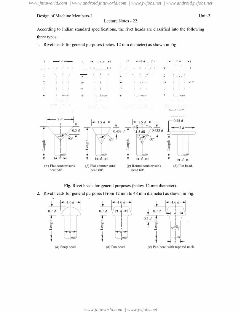
Design of Machine Members-I
According to Indian standard specifications, the rivet heads are classified into the following
three types:
1. Rivet heads for general purposes (below 1
Fig. Rivet heads for general purposes (below 12 mm diameter).
2. Rivet heads for general purposes (Fr
Lecture Notes - 22
specifications, the rivet heads are classified into the following
Rivet heads for general purposes (below 12 mm diameter) as shown in Fig.
Rivet heads for general purposes (below 12 mm diameter).
Rivet heads for general purposes (From 12 mm to 48 mm diameter) as shown in Fig.
Unit-3
specifications, the rivet heads are classified into the following
om 12 mm to 48 mm diameter) as shown in Fig.
www.jntuworld.com || www.android.jntuworld.com || www.jwjobs.net || www.android.jwjobs.net
www.jntuworld.com || www.jwjobs.net
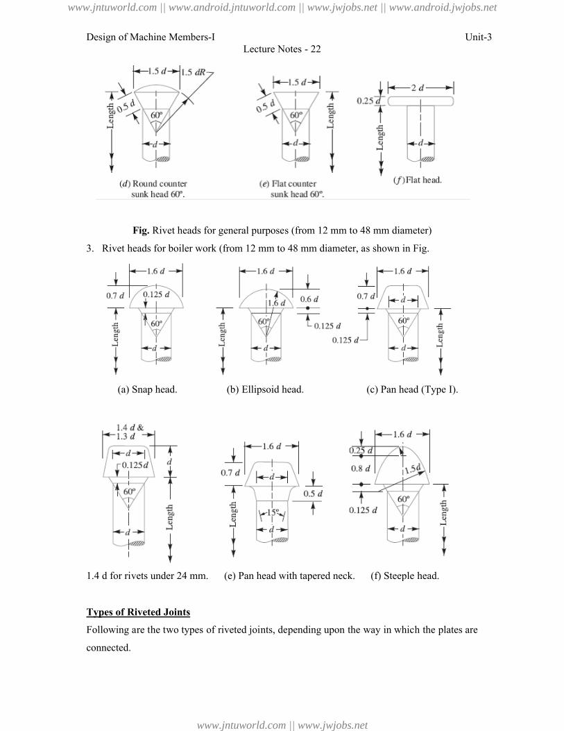
Design of Machine Members-I
Fig. Rivet heads for general purposes (from 12 mm to 48 mm diameter)
3. Rivet heads for boiler work (from 12 mm to 48 mm diameter, as shown in Fig.
(a) Snap head. (b) Ellipsoid head. (c) Pan head (Type I).
1.4 d for rivets under 24 mm. (e) Pan head with tapered neck. (f) Steeple head.
Types of Riveted Joints
Following are the two types of riveted joints, depending upon the way in which the plates are
connected.
Lecture Notes - 22
Rivet heads for general purposes (from 12 mm to 48 mm diameter)
Rivet heads for boiler work (from 12 mm to 48 mm diameter, as shown in Fig.
(a) Snap head. (b) Ellipsoid head. (c) Pan head (Type I).
1.4 d for rivets under 24 mm. (e) Pan head with tapered neck. (f) Steeple head.
of riveted joints, depending upon the way in which the plates are
Unit-3
Rivet heads for general purposes (from 12 mm to 48 mm diameter)
Rivet heads for boiler work (from 12 mm to 48 mm diameter, as shown in Fig.
(a) Snap head. (b) Ellipsoid head. (c) Pan head (Type I).
1.4 d for rivets under 24 mm. (e) Pan head with tapered neck. (f) Steeple head.
of riveted joints, depending upon the way in which the plates are
www.jntuworld.com || www.android.jntuworld.com || www.jwjobs.net || www.android.jwjobs.net
www.jntuworld.com || www.jwjobs.net
Design of Machine Members-I Unit-3Lecture Notes - 22
1. Lap joint, and
2. Butt joint.
1. Lap Joint
A lap joint is that in which one plate overlaps the other and the two plates are then riveted
together.
2. Butt Joint
A butt joint is that in which the main plates are kept in alignment butting (i.e. touching) each
other and a cover plate (i.e. strap) is placed either on one side or on both sides of the main
plates. The cover plate is then riveted together with the main plates. Butt joints are of the
following two types:
1. Single strap butt joint, and
2. Double strap butt joint.
In a single strap butt joint, the edges of the main plates butt against each other and only
one cover plate is placed on one side of the main plates and then riveted together. In a double
strap butt joint, the edges of the main plates butt against each other and two cover plates are
placed on both sides of the main plates and then riveted together.
In addition to the above, following are the types of riveted joints depending upon the
number of rows of the rivets.
1. Single riveted joint, and
2. Double riveted joint.
A single riveted joint is that in which there is a single row of rivets in a lap joint as
shown in Fig (a) and there is a single row of rivets on each side in a butt joint as shown in
Fig. A double riveted joint is that in which there are two rows of rivets in a lap joint as
shown in Fig. (b) and (c) and there are two rows of rivets on each side in a butt joint as shown
in Fig.
www.jntuworld.com || www.android.jntuworld.com || www.jwjobs.net || www.android.jwjobs.net
www.jntuworld.com || www.jwjobs.net
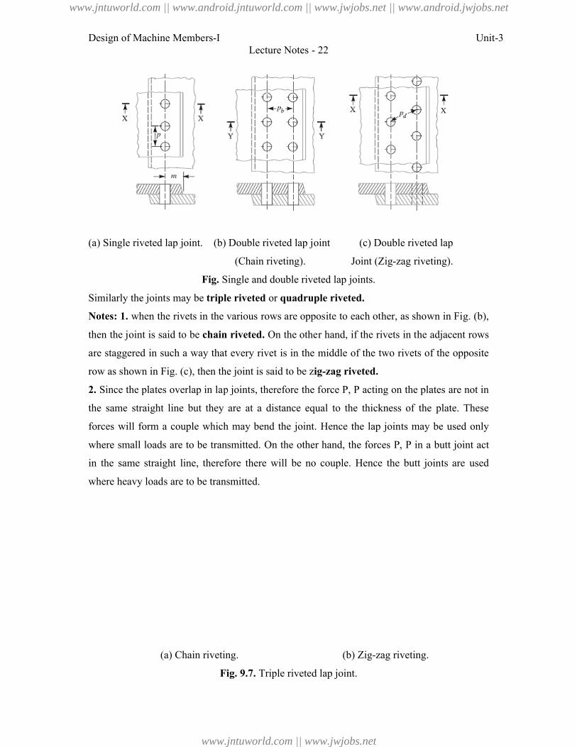
Design of Machine Members-I
(a) Single riveted lap joint. (b) Double riveted lap joint (c) Double riveted lap
Fig. Single and double riveted lap joints.
Similarly the joints may be triple riveted
Notes: 1. when the rivets in the various rows are opposite to each other, as shown in Fig. (
then the joint is said to be chain riveted
are staggered in such a way that every rivet is in the middle of the two rivets of the opposite
row as shown in Fig. (c), then the joint is said to be z
2. Since the plates overlap in lap joints, therefore the force
the same straight line but they are at a distance equal to the thickness of the plate. These
forces will form a couple which may bend the joint. Hence the lap joints may be used only
where small loads are to be transmitted. On the other hand, th
in the same straight line, therefore there will be no couple. Hence the butt joints are used
where heavy loads are to be transmitted.
(a) Chain riveting. (b) Zig
Fig. 9.7.
Lecture Notes - 22
) Single riveted lap joint. (b) Double riveted lap joint (c) Double riveted lap
(Chain riveting). Joint (Zig-zag riveting).
Single and double riveted lap joints.
triple riveted or quadruple riveted.
when the rivets in the various rows are opposite to each other, as shown in Fig. (
chain riveted. On the other hand, if the rivets in the adjacent rows
re staggered in such a way that every rivet is in the middle of the two rivets of the opposite
), then the joint is said to be zig-zag riveted.
Since the plates overlap in lap joints, therefore the force P, P acting on the plates
the same straight line but they are at a distance equal to the thickness of the plate. These
forces will form a couple which may bend the joint. Hence the lap joints may be used only
where small loads are to be transmitted. On the other hand, the forces P, P in a butt joint act
in the same straight line, therefore there will be no couple. Hence the butt joints are used
where heavy loads are to be transmitted.
(a) Chain riveting. (b) Zig-zag riveting.
Fig. 9.7. Triple riveted lap joint.
Unit-3
) Single riveted lap joint. (b) Double riveted lap joint (c) Double riveted lap
zag riveting).
when the rivets in the various rows are opposite to each other, as shown in Fig. (b),
On the other hand, if the rivets in the adjacent rows
re staggered in such a way that every rivet is in the middle of the two rivets of the opposite
acting on the plates are not in
the same straight line but they are at a distance equal to the thickness of the plate. These
forces will form a couple which may bend the joint. Hence the lap joints may be used only
in a butt joint act
in the same straight line, therefore there will be no couple. Hence the butt joints are used
www.jntuworld.com || www.android.jntuworld.com || www.jwjobs.net || www.android.jwjobs.net
www.jntuworld.com || www.jwjobs.net
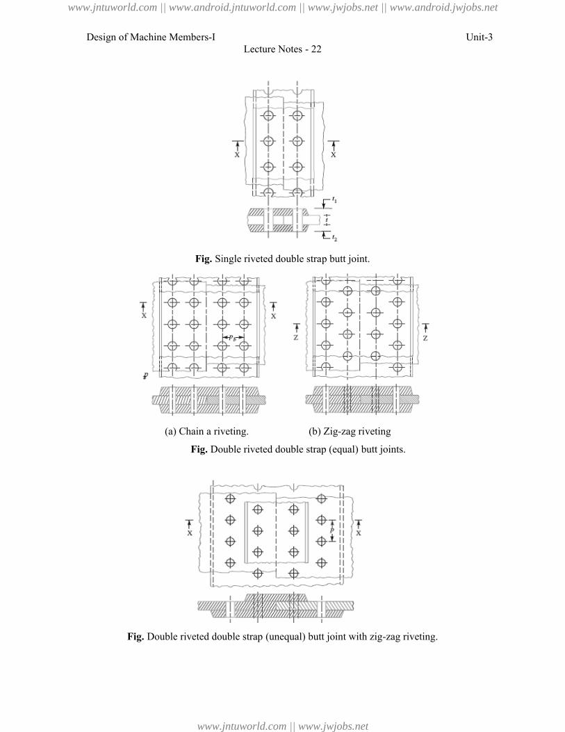
Design of Machine Members-I
Fig. Single riveted double strap butt joint.
(a) Chain a riveting.
Fig. Double riveted double strap (equal) butt joints.
Fig. Double riveted double strap (unequal) butt joint with zig
Lecture Notes - 22
Single riveted double strap butt joint.
riveting. (b) Zig-zag riveting
Double riveted double strap (equal) butt joints.
Double riveted double strap (unequal) butt joint with zig-zag riveting.
Unit-3
zag riveting.
www.jntuworld.com || www.android.jntuworld.com || www.jwjobs.net || www.android.jwjobs.net
www.jntuworld.com || www.jwjobs.net
Design of Machine Members-I Unit-3Lecture Notes - 22
References:
1. Machine Design - V.Bandari .
2. Machine Design – R.S. Khurmi
3. Design Data hand Book - S MD Jalaludin.
www.jntuworld.com || www.android.jntuworld.com || www.jwjobs.net || www.android.jwjobs.net
www.jntuworld.com || www.jwjobs.net
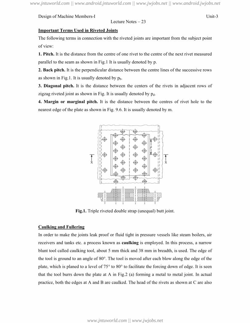
Design of Machine Members-I
Important Terms Used in Riveted Joints
The following terms in connection with the riveted joints are important from the subject point
of view:
1. Pitch. It is the distance from the centre of one rivet to the centre of the next rivet measured
parallel to the seam as shown in Fig.1
2. Back pitch. It is the perpendicular distance between the centre lines of the suc
as shown in Fig.1. It is usually denoted by
3. Diagonal pitch. It is the distance between the centers
zigzag riveted joint as shown in Fig. It is usually denoted by
4. Margin or marginal pitch.
nearest edge of the plate as shown in Fig. 9.6. It is usually den
Fig.1. Triple riveted double strap (unequal) butt joint.
Caulking and Fullering
In order to make the joints leak proof or fluid tight in pressure vessels like steam boilers, air
receivers and tanks etc. a process known as
blunt tool called caulking tool, about 5 mm thick and 38 mm in breadth, is used. The edge of
the tool is ground to an angle of 80°. The tool is moved after each blow along the edge of the
plate, which is planed to a level of 75
that the tool burrs down the plate at
practice, both the edges at A and
Lecture Notes – 23
Important Terms Used in Riveted Joints
The following terms in connection with the riveted joints are important from the subject point
It is the distance from the centre of one rivet to the centre of the next rivet measured
the seam as shown in Fig.1 It is usually denoted by p.
It is the perpendicular distance between the centre lines of the suc
It is usually denoted by pb.
It is the distance between the centers of the rivets in adjacent rows of
zigzag riveted joint as shown in Fig. It is usually denoted by pd.
. It is the distance between the centres of rivet hole to the
nearest edge of the plate as shown in Fig. 9.6. It is usually denoted by m.
Triple riveted double strap (unequal) butt joint.
In order to make the joints leak proof or fluid tight in pressure vessels like steam boilers, air
receivers and tanks etc. a process known as caulking is employed. In this process, a narrow
blunt tool called caulking tool, about 5 mm thick and 38 mm in breadth, is used. The edge of
the tool is ground to an angle of 80°. The tool is moved after each blow along the edge of the
plate, which is planed to a level of 75° to 80° to facilitate the forcing down of edge. It is seen
that the tool burrs down the plate at A in Fig.2 (a) forming a metal to metal joint. In actual
and B are caulked. The head of the rivets as shown at
Unit-3
The following terms in connection with the riveted joints are important from the subject point
It is the distance from the centre of one rivet to the centre of the next rivet measured
It is the perpendicular distance between the centre lines of the successive rows
of the rivets in adjacent rows of
It is the distance between the centres of rivet hole to the
In order to make the joints leak proof or fluid tight in pressure vessels like steam boilers, air
d. In this process, a narrow
blunt tool called caulking tool, about 5 mm thick and 38 mm in breadth, is used. The edge of
the tool is ground to an angle of 80°. The tool is moved after each blow along the edge of the
° to 80° to facilitate the forcing down of edge. It is seen
) forming a metal to metal joint. In actual
are caulked. The head of the rivets as shown at C are also
www.jntuworld.com || www.android.jntuworld.com || www.jwjobs.net || www.android.jwjobs.net
www.jntuworld.com || www.jwjobs.net
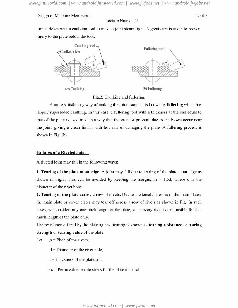
Design of Machine Members-I
turned down with a caulking tool to make a joint steam tight. A great care is taken to prevent
injury to the plate below the tool.
Fig.2.
A more satisfactory way of making the joints staunch is known as
largely superseded caulking. In this case, a fullering tool with a thickness at the end equal to
that of the plate is used in such a way that the greatest pressure due to the blows occur near
the joint, giving a clean finish, with less risk of damaging the plate.
shown in Fig. (b).
Failures of a Riveted Joint
A riveted joint may fail in the following ways
1. Tearing of the plate at an edge
shown in Fig.3. This can be avoided by ke
diameter of the rivet hole.
2. Tearing of the plate across a row of rivets
the main plate or cover plates may tear off across a
cases, we consider only one pitch length of the plate, since every rivet is responsible for that
much length of the plate only.
The resistance offered by the plate against tearing is known as
strength or tearing value of the plate.
Let p = Pitch of the rivets,
d = Diameter of the rivet hole,
t = Thickness of the plate, and
t = Permissible tensile stress for the plate material.
Lecture Notes – 23
down with a caulking tool to make a joint steam tight. A great care is taken to prevent
injury to the plate below the tool.
Fig.2. Caulking and fullering.
A more satisfactory way of making the joints staunch is known as fullering
superseded caulking. In this case, a fullering tool with a thickness at the end equal to
that of the plate is used in such a way that the greatest pressure due to the blows occur near
the joint, giving a clean finish, with less risk of damaging the plate. A fulleri
may fail in the following ways:
Tearing of the plate at an edge. A joint may fail due to tearing of the plate
. This can be avoided by keeping the margin, m = 1.5d, where
Tearing of the plate across a row of rivets. Due to the tensile stresses in the main plates,
the main plate or cover plates may tear off across a row of rivets as shown in Fig.
cases, we consider only one pitch length of the plate, since every rivet is responsible for that
The resistance offered by the plate against tearing is known as tearing resistance
the plate.
= Diameter of the rivet hole,
= Thickness of the plate, and
= Permissible tensile stress for the plate material.
Unit-3
down with a caulking tool to make a joint steam tight. A great care is taken to prevent
fullering which has
superseded caulking. In this case, a fullering tool with a thickness at the end equal to
that of the plate is used in such a way that the greatest pressure due to the blows occur near
A fullering process is
A joint may fail due to tearing of the plate at an edge as
, where d is the
Due to the tensile stresses in the main plates,
row of rivets as shown in Fig. In such
cases, we consider only one pitch length of the plate, since every rivet is responsible for that
tearing resistance or tearing
www.jntuworld.com || www.android.jntuworld.com || www.jwjobs.net || www.android.jwjobs.net
www.jntuworld.com || www.jwjobs.net
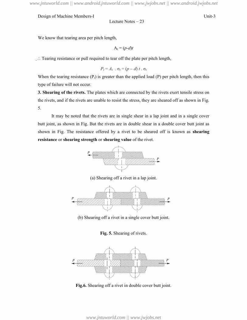
Design of Machine Members-I
We know that tearing area per pitch length,
Tearing resistance or pull required to tear off the plate per pitch length,
When the tearing resistance (Pt) is greater than the applied load (
type of failure will not occur.
3. Shearing of the rivets. The plates which are connected by the rivets exert tensile stress on
the rivets, and if the rivets are unable to resist the stress, they are s
5.
It may be noted that the rivets are in single shear in a lap joint and in a
butt joint, as shown in Fig. But the rivets are in double shear in a double cover
shown in Fig. The resistance offered by a rivet to be sheared off is known as
resistance or shearing strength
(a) Shearing off a rivet in a lap joint.
(b) Shearing off a rivet in a single cover butt joint.
Fig.6. Shearing off a rivet in double cover butt joint.
Lecture Notes – 23
We know that tearing area per pitch length,
At = (p-d)t
Tearing resistance or pull required to tear off the plate per pitch length,
Pt = At . σt = (p – d) t . σt
) is greater than the applied load (P) per pitch length, then this
The plates which are connected by the rivets exert tensile stress on
the rivets, and if the rivets are unable to resist the stress, they are sheared off as shown in Fig.
It may be noted that the rivets are in single shear in a lap joint and in a
butt joint, as shown in Fig. But the rivets are in double shear in a double cover
. The resistance offered by a rivet to be sheared off is known as
shearing strength or shearing value of the rivet.
(a) Shearing off a rivet in a lap joint.
(b) Shearing off a rivet in a single cover butt joint.
Fig. 5. Shearing of rivets.
Shearing off a rivet in double cover butt joint.
Unit-3
) per pitch length, then this
The plates which are connected by the rivets exert tensile stress on
heared off as shown in Fig.
It may be noted that the rivets are in single shear in a lap joint and in a single cover
butt joint, as shown in Fig. But the rivets are in double shear in a double cover butt joint as
. The resistance offered by a rivet to be sheared off is known as shearing
www.jntuworld.com || www.android.jntuworld.com || www.jwjobs.net || www.android.jwjobs.net
www.jntuworld.com || www.jwjobs.net
Design of Machine Members-I Unit-3Lecture Notes – 23
Let d = Diameter of the rivet hole,
= Safe permissible shear stress for the rivet material, and
n = Number of rivets per pitch length.
We know that shearing area,
2
4dAs
...(In single shear)
2
42 d
... (Theoretically, in double shear)
2
4875.1 d
... (In double shear, according to Indian Boiler Regulations)
Shearing resistance or pull required to shear off the rivet per pitch length,
τ4
2 dnPs
... (In single shear)
τ4
2 2 dn
... (Theoretically, in double shear)
As we discussed earlier, when the shearing takes place at one cross-section of the rivet, then
the rivets are said to be in single shear. Similarly, when the shearing takes place at two cross-
sections of the rivet, then the rivets are said to be in double shear.
τ4
875.1 2 dn
... (In double shear, according to Indian Boiler Regulations)
When the shearing resistance (Ps) is greater than the applied load (P) per pitch length,
then this type of failure will occur.
4. Crushing of the plate or rivets. Sometimes, the rivets do not actually shear off under the
tensile stress, but are crushed as shown in Fig. Due to this, the rivet hole becomes of an oval
shape and hence the joint becomes loose. The failure of rivets in such a manner is also known
as bearing failure. The area which resists this action is the projected area of the hole or rivet
on diametric plane.
The resistance offered by a rivet to be crushed is known as crushing resistance or
crushing strength or bearing value of the rivet.
Let d = Diameter of the rivet hole,
t = Thickness of the plate,
c = Safe permissible crushing stress for the rivet or plate material, and
www.jntuworld.com || www.android.jntuworld.com || www.jwjobs.net || www.android.jwjobs.net
www.jntuworld.com || www.jwjobs.net
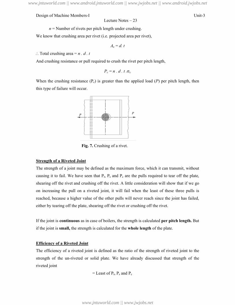
Design of Machine Members-I
n = Number of rivets per pitch length u
We know that crushing area per rivet (
Total crushing area = n . d . t
And crushing resistance or pull required to crush the rivet per pitch length,
When the crushing resistance (P
this type of failure will occur.
Fig. 7.
Strength of a Riveted Joint
The strength of a joint may be defined as the maximum fo
causing it to fail. We have seen
shearing off the rivet and crushing off the rivet. A little consideration will show that if we go
on increasing the pull on a riveted joint, it will fail when the least of these three pulls is
reached, because a higher value of the other pulls will never reach since the joint has failed,
either by tearing off the plate, shearing off the rivet or crushing off the rivet.
If the joint is continuous as in case of boilers, the strength is calculated
if the joint is small, the strength is calculated for the
Efficiency of a Riveted Joint
The efficiency of a riveted joint is defined a
strength of the un-riveted or solid plate.
riveted joint
= Least of
Lecture Notes – 23
= Number of rivets per pitch length under crushing.
We know that crushing area per rivet (i.e. projected area per rivet),
Ac = d. t
nd crushing resistance or pull required to crush the rivet per pitch length,
Pc = n . d . t .c
Pc) is greater than the applied load (P) per pitch length, then
7. Crushing of a rivet.
The strength of a joint may be defined as the maximum force, which it can transmit, without
that Pt, Ps and Pc are the pulls required to tear off the plate,
shearing off the rivet and crushing off the rivet. A little consideration will show that if we go
n a riveted joint, it will fail when the least of these three pulls is
reached, because a higher value of the other pulls will never reach since the joint has failed,
either by tearing off the plate, shearing off the rivet or crushing off the rivet.
as in case of boilers, the strength is calculated per pitch length
the strength is calculated for the whole length of the plate.
The efficiency of a riveted joint is defined as the ratio of the strength of riveted joint to the
riveted or solid plate. We have already discussed that strength of the
= Least of Pt, Ps and Pc
Unit-3
) per pitch length, then
rce, which it can transmit, without
are the pulls required to tear off the plate,
shearing off the rivet and crushing off the rivet. A little consideration will show that if we go
n a riveted joint, it will fail when the least of these three pulls is
reached, because a higher value of the other pulls will never reach since the joint has failed,
per pitch length. But
s the ratio of the strength of riveted joint to the
already discussed that strength of the
www.jntuworld.com || www.android.jntuworld.com || www.jwjobs.net || www.android.jwjobs.net
www.jntuworld.com || www.jwjobs.net
Design of Machine Members-I Unit-3Lecture Notes – 23
Strength of the un-riveted or solid plate per pitch length,
P = p . t .t
Efficiency of the riveted joint,
tσ
and,ofLeast
tp
PPP cst
Where p = Pitch of the rivets,
t = Thickness of the plate, and
σt = Permissible tensile stress of the plate material.
References:
1. Machine Design - V.Bandari .
2. Machine Design – R.S. Khurmi
3. Design Data hand Book - S MD Jalaludin.
www.jntuworld.com || www.android.jntuworld.com || www.jwjobs.net || www.android.jwjobs.net
www.jntuworld.com || www.jwjobs.net
Design of Machine Members-I
Problems on design of riveted joints
Problem:
A double riveted lap joint is made between 15 mm thick plates. The rivet diameter
are 25 mm and 75 mm respectively. If the ultimate stresses are 400 MPa in tension,
in shear and 640 MPa in crushing, find the minimum force per pitch which will rupture
joint. If the above joint is subjected to a load such that the factor of safety is 4, find out the
actual stresses developed in the plates and the rivets.
Problem
Lecture Notes – 24
Problems on design of riveted joints
A double riveted lap joint is made between 15 mm thick plates. The rivet diameter
are 25 mm and 75 mm respectively. If the ultimate stresses are 400 MPa in tension,
crushing, find the minimum force per pitch which will rupture
If the above joint is subjected to a load such that the factor of safety is 4, find out the
stresses developed in the plates and the rivets.
Unit-3
A double riveted lap joint is made between 15 mm thick plates. The rivet diameter and pitch
are 25 mm and 75 mm respectively. If the ultimate stresses are 400 MPa in tension, 320 MPa
crushing, find the minimum force per pitch which will rupture the
If the above joint is subjected to a load such that the factor of safety is 4, find out the
www.jntuworld.com || www.android.jntuworld.com || www.jwjobs.net || www.android.jwjobs.net
www.jntuworld.com || www.jwjobs.net
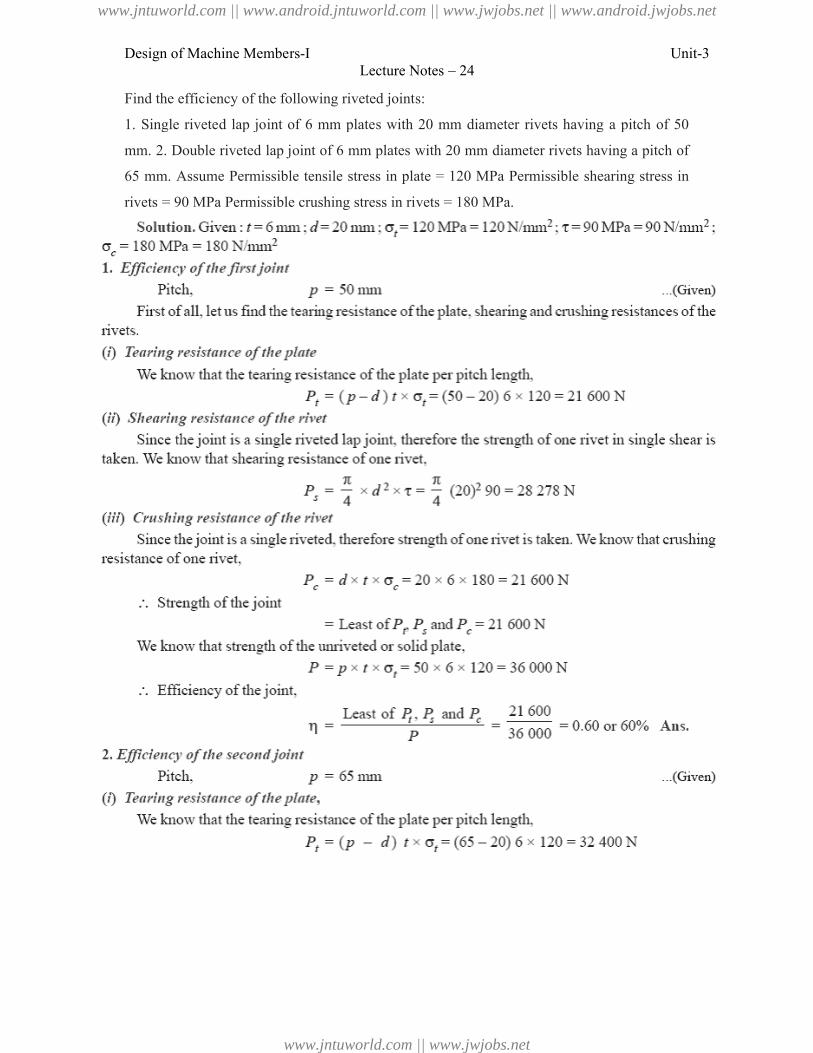
Design of Machine Members-I
Find the efficiency of the following riveted joints:
1. Single riveted lap joint of 6 mm plates with 20 mm diameter rivets having a pitch of 50
mm. 2. Double riveted lap joint of 6 mm plates with 20 mm diameter rivets having a pitch of
65 mm. Assume Permissible tensile stress in
rivets = 90 MPa Permissible crushing stress in rivets = 180 MPa
Lecture Notes – 24
he following riveted joints:
1. Single riveted lap joint of 6 mm plates with 20 mm diameter rivets having a pitch of 50
2. Double riveted lap joint of 6 mm plates with 20 mm diameter rivets having a pitch of
Assume Permissible tensile stress in plate = 120 MPa Permissible shearing stress in
Permissible crushing stress in rivets = 180 MPa.
Unit-3
1. Single riveted lap joint of 6 mm plates with 20 mm diameter rivets having a pitch of 50
2. Double riveted lap joint of 6 mm plates with 20 mm diameter rivets having a pitch of
Permissible shearing stress in
www.jntuworld.com || www.android.jntuworld.com || www.jwjobs.net || www.android.jwjobs.net
www.jntuworld.com || www.jwjobs.net
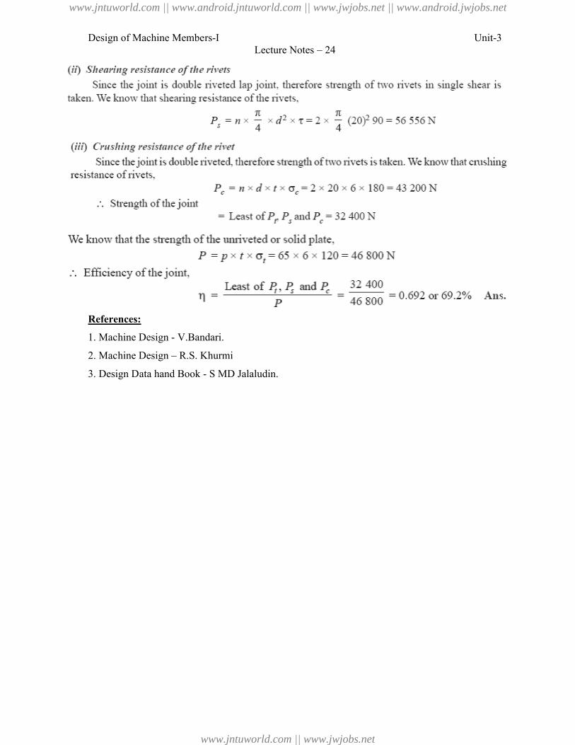
Design of Machine Members-I
References:
1. Machine Design - V.Bandari.
2. Machine Design – R.S. Khurmi
3. Design Data hand Book - S MD Jalaludin.
Lecture Notes – 24
R.S. Khurmi
S MD Jalaludin.
Unit-3
www.jntuworld.com || www.android.jntuworld.com || www.jwjobs.net || www.android.jwjobs.net
www.jntuworld.com || www.jwjobs.net
Design of Machine Members-I Unit-3Lecture Notes – 25
Design of boiler joints according to IBR
Design of Boiler Joints
The boiler has a longitudinal joint as well as circumferential joint. The longitudinal joint is
used to join the ends of the plate to get the required diameter of a boiler. For this purpose, a
butt joint with two cover plates is used. The circumferential joint is used to get the required
length of the boiler. For this purpose, a lap joint with one ring overlapping the other
alternately is used.
Since a boiler is made up of number of rings, therefore the longitudinal joints are staggered
for convenience of connecting rings at places where both longitudinal and circumferential
joints occur.
Design of Longitudinal Butt Joint for a Boiler
According to Indian Boiler Regulations (I.B.R), the following procedure should be adopted
for the design of longitudinal butt joint for a boiler.
1. Thickness of boiler shell. First of all, the thickness of the boiler shell is determined by
using the thin cylindrical formula, i.e.
Where t = Thickness of the boiler shell,
P = Steam pressure in boiler,
D = Internal diameter of boiler shell,
σt = Permissible tensile stress, and
ηl = Efficiency of the longitudinal joint.
The following points may be noted:
(a) The thickness of the boiler shell should not be less than 7 mm.
(b) The efficiency of the joint may be taken from the following table.
Indian Boiler Regulations (I.B.R.) allows a maximum efficiency of 85% for the best joint.
(c) According to I.B.R., the factor of safety should not be less than 4.
2. Diameter of rivets. After finding out the thickness of the boiler shell (t), the diameter of the
rivet hole (d) may be determined by using Unwin's empirical formula,
i.e. d = 6 t (when t is greater than 8 mm)
But if the thickness of plate is less than 8 mm, then the diameter of the rivet hole may be
calculated by equating the shearing resistance of the rivets to crushing resistance. In no case,
www.jntuworld.com || www.android.jntuworld.com || www.jwjobs.net || www.android.jwjobs.net
www.jntuworld.com || www.jwjobs.net
Design of Machine Members-I Unit-3Lecture Notes – 25
the diameter of rivet hole should not be less than the thickness of the plate, because there will
be danger of punch crushing.
3. Pitch of rivets. The pitch of the rivets is obtained by equating the tearing resistance of the
plate to the shearing resistance of the rivets. It may noted that (a) The pitch of the rivets
should not be less than 2d, which is necessary for the formation of head.
(b) The maximum value of the pitch of rivets for a longitudinal joint of a boiler as per I.B.R.
is pmax = C × t + 41.28 mm where t = Thickness of the shell plate in mm, and C = Constant.
The value of the constant C may be taken from DDB. If the pitch of rivets as obtained by
equating the tearing resistance to the shearing resistance is more than pmax, then the value of
pmax is taken.
4. Distance between the rows of rivets. The distance between the rows of rivets as specified
by Indian Boiler Regulations is as follows:
(a) For equal number of rivets in more than one row for lap joint or butt joint, the distance
between the rows of rivets ( pb) should not be less than 0.33 p + 0.67 d, for zig-zig riveting,
and 2 d, for chain riveting.
(b) For joints in which the number of rivets in outer rows is half the number of rivets in inner
rows and if the inner rows are chain riveted, the distance between the outer rows and the next
rows should not be less than 0.33 p + 0.67 or 2 d, whichever is greater. The distance between
the rows in which there are full number of rivets shall not be less than 2d.
(c) For joints in which the number of rivets in outer rows is half the number of rivets in inner
rows and if the inner rows are zig-zig riveted, the distance between the outer rows and the
next rows shall not be less than 0.2 p + 1.15 d. The distance between the rows in which there
are full number of rivets (zig-zag) shall not be less than 0.165 p + 0.67 d.
Note : In the above discussion, p is the pitch of the rivets in the outer rows.
5. Thickness of butt strap. According to I.B.R., the thicknesses for butt strap (t1) are as given
below:
(a) The thickness of butt strap, in no case, shall be less than 10 mm.
(b) tt = 1.125 t, for ordinary (chain riveting) single butt strap.
For single butt straps, every alternate rivet in outer rows being omitted.
t1 = 0.625 t, for double butt-straps of equal width having ordinary riveting (chain riveting).
www.jntuworld.com || www.android.jntuworld.com || www.jwjobs.net || www.android.jwjobs.net
www.jntuworld.com || www.jwjobs.net
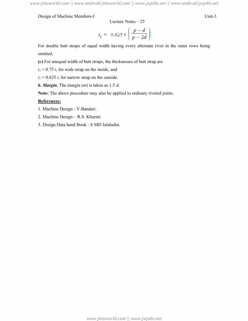
Design of Machine Members-I Unit-3Lecture Notes – 25
For double butt straps of equal width having every alternate rivet in the outer rows being
omitted.
(c) For unequal width of butt straps, the thicknesses of butt strap are
t1 = 0.75 t, for wide strap on the inside, and
t1 = 0.625 t, for narrow strap on the outside.
6. Margin. The margin (m) is taken as 1.5 d.
Note: The above procedure may also be applied to ordinary riveted joints.
References:
1. Machine Design - V.Bandari .
2. Machine Design – R.S. Khurmi
3. Design Data hand Book - S MD Jalaludin.
www.jntuworld.com || www.android.jntuworld.com || www.jwjobs.net || www.android.jwjobs.net
www.jntuworld.com || www.jwjobs.net
Design of Machine Members-I Unit-3Lecture Notes – 28
Design of eccentric loaded riveted joints and Problems
Eccentric Loaded Riveted Joint
When the line of action of the load does not pass through the centroid of the rivet system and
thus all rivets are not equally loaded, then the joint is said to be an eccentric loaded riveted
joint, as shown in Fig. 1(a). The eccentric loading results in secondary shear caused by the
tendency of force to twist the joint about the centre of gravity in addition to direct shear or
primary shear.
Let P = Eccentric load on the joint, and
e = Eccentricity of the load i.e. the distance between the line of action of the
load and the centroid of the rivet system i.e. G.
The following procedure is adopted for the design of an eccentrically loaded riveted joint.
Note: This picture is given as additional information and is not a direct example of the current
chapter.
1. First of all, find the centre of gravity G of the rivet system.
Let A = Cross-sectional area of each rivet,
x1, x2, x3 etc. = Distances of rivets from OY, and
y=, y2, y3 etc. = Distances of rivets from OX.
We know that n.A
...AxAxAx
;;;AAA
...xAxAxAx 321
321
332211
n
...xxx 321 …(where n = Number of rivets)
Similarly, n
...3y2y1yy
www.jntuworld.com || www.android.jntuworld.com || www.jwjobs.net || www.android.jwjobs.net
www.jntuworld.com || www.jwjobs.net
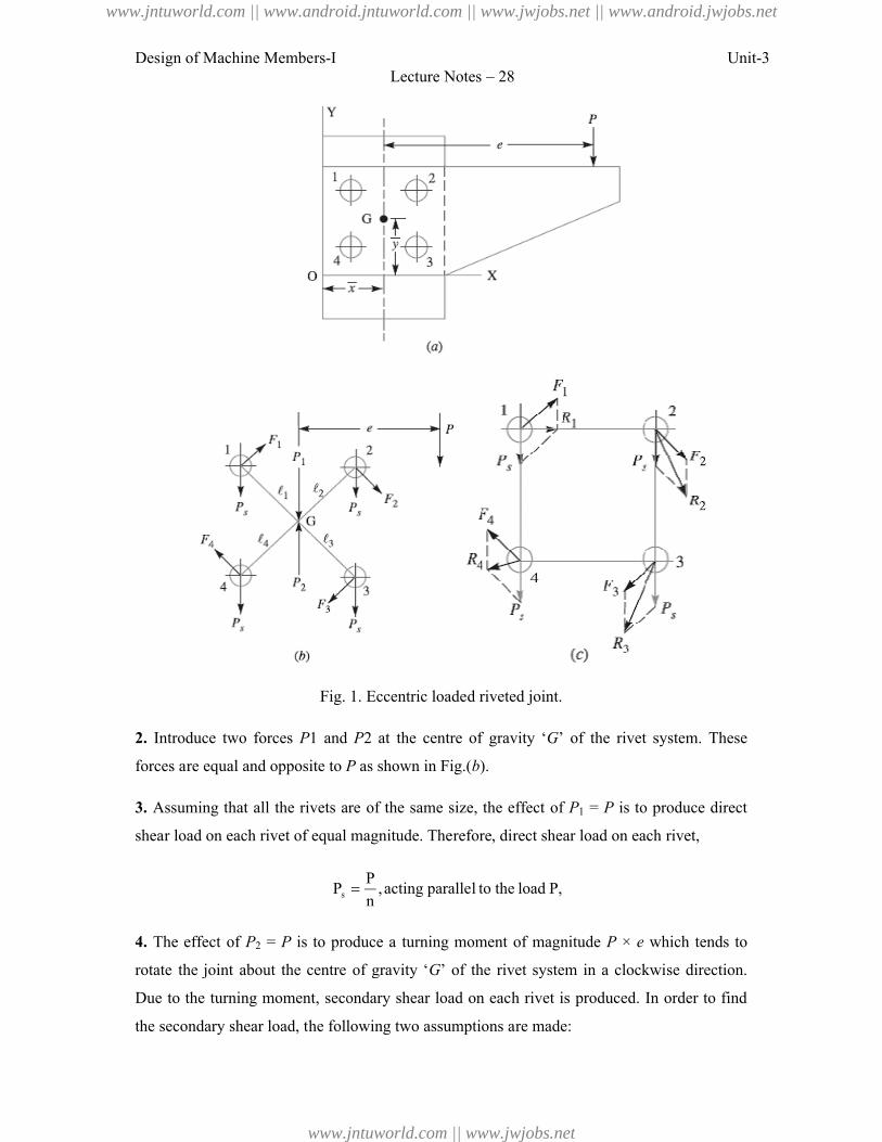
Design of Machine Members-I
Fig. 1.
2. Introduce two forces P1 and
forces are equal and opposite to P
3. Assuming that all the rivets are of the same size, the effect of
shear load on each rivet of equal magnitude. Therefore, direct shear load on each rivet,
Ps
4. The effect of P2 = P is to produce a turning moment of magnitude
rotate the joint about the centre of gravity ‘
Due to the turning moment, secondary shear load on each rivet is produced. In order to find
the secondary shear load, the following two assumptions are made:
Lecture Notes – 28
Fig. 1. Eccentric loaded riveted joint.
1 and P2 at the centre of gravity ‘G’ of the rivet system. These
P as shown in Fig.(b).
Assuming that all the rivets are of the same size, the effect of P1 = P is to produce direct
shear load on each rivet of equal magnitude. Therefore, direct shear load on each rivet,
P,load the toparallelacting,n
P
is to produce a turning moment of magnitude P × e which tends to
rotate the joint about the centre of gravity ‘G’ of the rivet system in a clockwise direction.
Due to the turning moment, secondary shear load on each rivet is produced. In order to find
secondary shear load, the following two assumptions are made:
Unit-3
’ of the rivet system. These
is to produce direct
shear load on each rivet of equal magnitude. Therefore, direct shear load on each rivet,
which tends to
’ of the rivet system in a clockwise direction.
Due to the turning moment, secondary shear load on each rivet is produced. In order to find
www.jntuworld.com || www.android.jntuworld.com || www.jwjobs.net || www.android.jwjobs.net
www.jntuworld.com || www.jwjobs.net
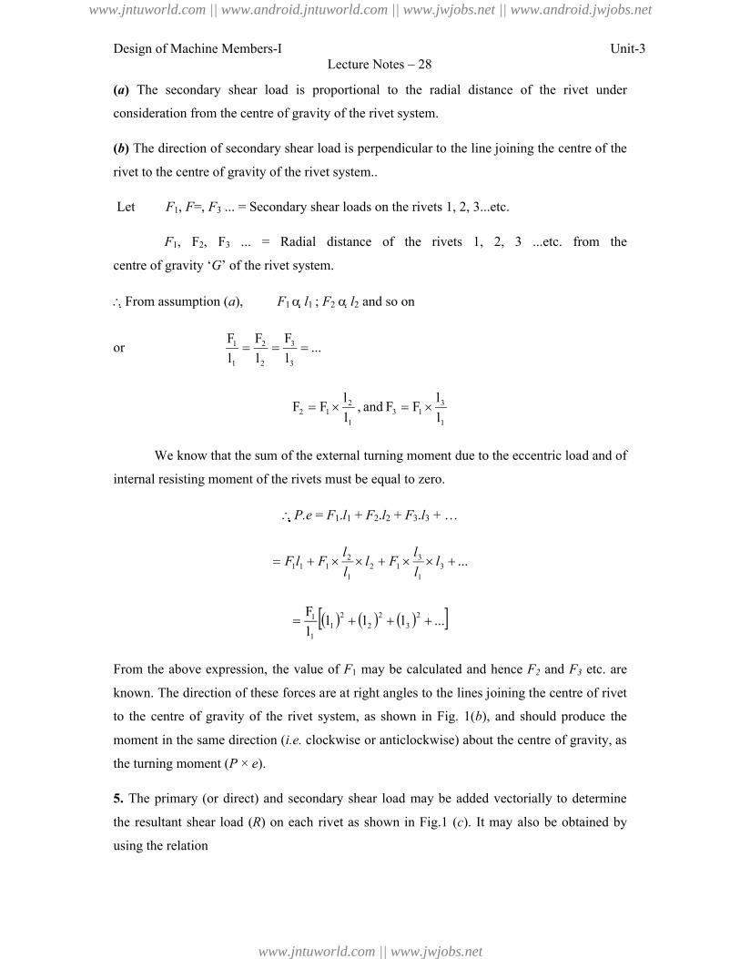
Design of Machine Members-I Unit-3Lecture Notes – 28
(a) The secondary shear load is proportional to the radial distance of the rivet under
consideration from the centre of gravity of the rivet system.
(b) The direction of secondary shear load is perpendicular to the line joining the centre of the
rivet to the centre of gravity of the rivet system..
Let F1, F=, F3 ... = Secondary shear loads on the rivets 1, 2, 3...etc.
F1, F2, F3 ... = Radial distance of the rivets 1, 2, 3 ...etc. from the
centre of gravity ‘G’ of the rivet system.
From assumption (a), F1 l1 ; F2 l2 and so on
or ...l
F
l
F
l
F
3
3
2
2
1
1
1
313
1
212 l
lFFand,
l
lFF
We know that the sum of the external turning moment due to the eccentric load and of
internal resisting moment of the rivets must be equal to zero.
P.e = F1.l1 + F2.l2 + F3.l3 + …
...31
312
1
2111 l
l
lFl
l
lFlF
...llll
F 23
22
21
1
1
From the above expression, the value of F1 may be calculated and hence F2 and F3 etc. are
known. The direction of these forces are at right angles to the lines joining the centre of rivet
to the centre of gravity of the rivet system, as shown in Fig. 1(b), and should produce the
moment in the same direction (i.e. clockwise or anticlockwise) about the centre of gravity, as
the turning moment (P × e).
5. The primary (or direct) and secondary shear load may be added vectorially to determine
the resultant shear load (R) on each rivet as shown in Fig.1 (c). It may also be obtained by
using the relation
www.jntuworld.com || www.android.jntuworld.com || www.jwjobs.net || www.android.jwjobs.net
www.jntuworld.com || www.jwjobs.net
Design of Machine Members-I
R
Where = Angle between the primary or direct shear load (P
And secondary shear load (F).
When the secondary shear load on each rivet is equal, then the heavily loaded rivet
will be one in which the included angle
load is minimum. The maximum loaded rivet becomes the critical one for determining the
strength of the riveted joint. Knowing the permissible shear stress (
rivet hole may be obtained by using the relation,
Maximum resultant shear load (
From DDB, the standard diameter of the rivet hole (
specified
Notes : 1. In the solution of a problem, the primary and shear loads may be
approximately to scale and generally the rivet having the maximum resultant shear load will
be apparent by inspection. The values of the load for that rivet may then be calculated.
2. When the thickness of the plate is given, then the diameter of
checked against crushing.
3. When the eccentric load P is inclined at some angle, then the same procedure as discussed
above may be followed to find the size of rivet.
Problem: An eccentrically loaded lap riveted joint is to be desig
shown in Fig. 2. The bracket plate is 25 mm
thick. All rivets are to be of the same size. Load
on the bracket, P = 50 kN ; rivet spacing, C =
100 mm; load arm, e = 400 mm.
shear stress is 65 MPa and crushing stress
120 MPa. Determine the size of the rivets to be
used for the joint.
Lecture Notes – 28
θcosF2PsFP 22
s
= Angle between the primary or direct shear load (Ps)
When the secondary shear load on each rivet is equal, then the heavily loaded rivet
will be one in which the included angle between the direct shear load and secondary shear
load is minimum. The maximum loaded rivet becomes the critical one for determining the
strength of the riveted joint. Knowing the permissible shear stress (), the diameter of the
d by using the relation,
Maximum resultant shear load (R) = 2
4d
, the standard diameter of the rivet hole ( d ) and the rivet diameter may be
In the solution of a problem, the primary and shear loads may be
approximately to scale and generally the rivet having the maximum resultant shear load will
be apparent by inspection. The values of the load for that rivet may then be calculated.
When the thickness of the plate is given, then the diameter of the rivet hole may be
is inclined at some angle, then the same procedure as discussed
lowed to find the size of rivet.
An eccentrically loaded lap riveted joint is to be designed for a steel bracket as
shown in Fig. 2. The bracket plate is 25 mm
thick. All rivets are to be of the same size. Load
on the bracket, P = 50 kN ; rivet spacing, C =
100 mm; load arm, e = 400 mm. Permissible
shear stress is 65 MPa and crushing stress is
120 MPa. Determine the size of the rivets to be
Unit-3
When the secondary shear load on each rivet is equal, then the heavily loaded rivet
between the direct shear load and secondary shear
load is minimum. The maximum loaded rivet becomes the critical one for determining the
), the diameter of the
) and the rivet diameter may be
In the solution of a problem, the primary and shear loads may be laid off
approximately to scale and generally the rivet having the maximum resultant shear load will
be apparent by inspection. The values of the load for that rivet may then be calculated.
the rivet hole may be
is inclined at some angle, then the same procedure as discussed
ned for a steel bracket as
www.jntuworld.com || www.android.jntuworld.com || www.jwjobs.net || www.android.jwjobs.net
www.jntuworld.com || www.jwjobs.net
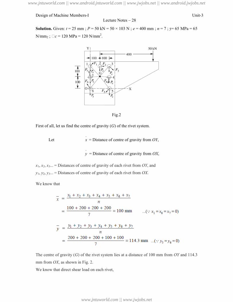
Design of Machine Members-I
Solution. Given: t = 25 mm ; P = 50 kN = 50 × 103 N ;
N/mm2 ; �c = 120 MPa = 120 N/mm
First of all, let us find the centre of gravity (
Let
x = Distance of centre of gravity from
y = Distance of centre of gravity from
x1, x2, x3... = Distances of centre of gravity of each rivet from
y1, y2, y3... = Distances of centre of gravity of each rivet from
We know that
The centre of gravity (G) of the rivet system lies at a distance of 100 mm from
mm from OX, as shown in Fig. 2
We know that direct shear load on each rivet,
Lecture Notes – 28
= 50 kN = 50 × 103 N ; e = 400 mm ; n = 7 ; = 65 MPa = 65
= 120 MPa = 120 N/mm2.
Fig.2
First of all, let us find the centre of gravity (G) of the rivet system.
= Distance of centre of gravity from OY,
= Distance of centre of gravity from OX,
... = Distances of centre of gravity of each rivet from OY, and
... = Distances of centre of gravity of each rivet from OX.
) of the rivet system lies at a distance of 100 mm from OY
as shown in Fig. 2.
We know that direct shear load on each rivet,
Unit-3
= 65 MPa = 65
OY and 114.3
www.jntuworld.com || www.android.jntuworld.com || www.jwjobs.net || www.android.jwjobs.net
www.jntuworld.com || www.jwjobs.net
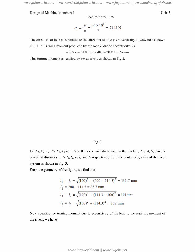
Design of Machine Members-I
The direct shear load acts parallel to the direction of load
in Fig. 2. Turning moment produced by the load
= P × e
This turning moment is resisted b
Let F1, F2, F3, F4, F5, F6 and F7 be the secondary shear load on the rivets 1, 2, 3, 4, 5, 6 and 7
placed at distances l1, l2, l3, l4, l5
system as shown in Fig. 3.
From the geometry of the figure, we find that
Now equating the turning moment due to eccentricity of the load to the resisting moment of
the rivets, we have
Lecture Notes – 28
The direct shear load acts parallel to the direction of load P i.e. vertically downward as shown
Turning moment produced by the load P due to eccentricity (e)
e = 50 × 103 × 400 = 20 × 106 N-mm
This turning moment is resisted by seven rivets as shown in Fig.2.
Fig. 3
be the secondary shear load on the rivets 1, 2, 3, 4, 5, 6 and 7
5, l6 and l7 respectively from the centre of gravity of the rivet
From the geometry of the figure, we find that
Now equating the turning moment due to eccentricity of the load to the resisting moment of
Unit-3
. vertically downward as shown
be the secondary shear load on the rivets 1, 2, 3, 4, 5, 6 and 7
respectively from the centre of gravity of the rivet
Now equating the turning moment due to eccentricity of the load to the resisting moment of
www.jntuworld.com || www.android.jntuworld.com || www.jwjobs.net || www.android.jwjobs.net
www.jntuworld.com || www.jwjobs.net
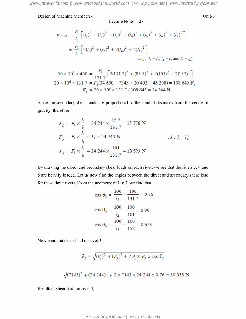
Design of Machine Members-I Unit-3Lecture Notes – 28
Since the secondary shear loads are proportional to their radial distances from the centre of
gravity, therefore
By drawing the direct and secondary shear loads on each rivet, we see that the rivets 3, 4 and
5 are heavily loaded. Let us now find the angles between the direct and secondary shear load
for these three rivets. From the geometry of Fig.3, we find that
Now resultant shear load on rivet 3,
Resultant shear load on rivet 4,
www.jntuworld.com || www.android.jntuworld.com || www.jwjobs.net || www.android.jwjobs.net
www.jntuworld.com || www.jwjobs.net
Design of Machine Members-I Unit-3Lecture Notes – 28
And resultant shear load on rivet 5,
The resultant shear load may be determined graphically, as shown in Fig.3.
From above we see that the maximum resultant shear load is on rivet 5. If d is the diameter of
rivet hole, then maximum resultant shear load (R5),
From DDB, we see that according the standard diameter of the rivet hole (d) is 25.5 mm and
the corresponding diameter of rivet is 24 mm.
Let us now check the joint for crushing stress. We know that
Since this stress is well below the given crushing stress of 120 MPa, therefore the design is
satisfactory.
References:
1. Machine Design - V.Bandari
2. Machine Design – R.S. Khurmi
3. Design Data hand Book - S MD Jalaludin.
www.jntuworld.com || www.android.jntuworld.com || www.jwjobs.net || www.android.jwjobs.net
www.jntuworld.com || www.jwjobs.net
Design of Machine Members-I Unit-3Lecture Notes – 29
Introduction to Welded Joints
Introduction
A welded joint is a permanent joint which is obtained by the fusion of the edges of the two
parts to be joined together, with or without the application of pressure and a filler material.
The heat required for the fusion of the material may be obtained by burning of gas (in case of
gas welding) or by an electric arc (in case of electric arc welding). The latter method is
extensively used because of greater speed of welding. Welding is extensively used in
fabrication as an alternative method for casting or forging and as a replacement for bolted and
riveted joints. It is also used as a repair medium e.g. to reunite metal at a crack, to build up a
small part that has broken off such as gear tooth or to repair a worn surface such as a bearing
surface.
Advantages and Disadvantages of Welded Joints over Riveted Joints
Following are the advantages and disadvantages of welded joints over riveted joints.
Advantages
1. The welded structures are usually lighter than riveted structures. This is due to the reason,
that in welding, gussets or other connecting components are not used.
2. The welded joints provide maximum efficiency (may be 100%) which is not possible in
case of riveted joints.
3. Alterations and additions can be easily made in the existing structures.
4. As the welded structure is smooth in appearance, therefore it looks pleasing.
5. In welded connections, the tension members are not weakened as in the case of riveted
joints.
6. A welded joint has a great strength. Often a welded joint has the strength of the parent
metal itself.
7. Sometimes, the members are of such a shape (i.e. circular steel pipes) that they afford
difficulty for riveting. But they can be easily welded.
8. The welding provides very rigid joints. This is in line with the modern trend of providing
rigid frames.
9. It is possible to weld any part of a structure at any point. But riveting requires enough
clearance.
10. The process of welding takes less time than the riveting.
Disadvantages
www.jntuworld.com || www.android.jntuworld.com || www.jwjobs.net || www.android.jwjobs.net
www.jntuworld.com || www.jwjobs.net
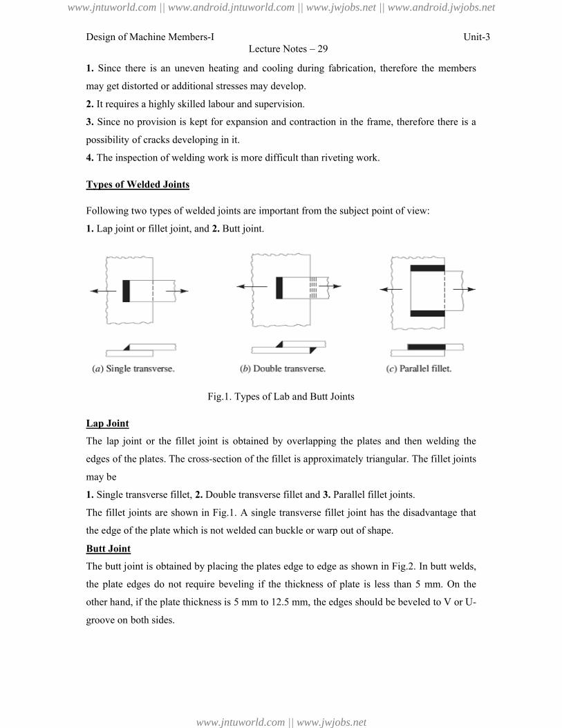
Design of Machine Members-I
1. Since there is an uneven heating and cooling during fabrication, therefore the members
may get distorted or additional stresses may develop.
2. It requires a highly skilled labour and supervision.
3. Since no provision is kept for expansion and contraction in t
possibility of cracks developing in it.
4. The inspection of welding work is more difficult than riveting work.
Types of Welded Joints
Following two types of welded joints are
1. Lap joint or fillet joint, and 2.
Fig.1. Types of Lab and Butt Joints
Lap Joint
The lap joint or the fillet joint is obtained by overlapping the plates and then welding the
edges of the plates. The cross-section of the fillet is approximately
may be
1. Single transverse fillet, 2. Double transverse
The fillet joints are shown in Fig.1
the edge of the plate which is not welded can buckle or warp out of shape.
Butt Joint
The butt joint is obtained by placing the plate
the plate edges do not require beveling
other hand, if the plate thickness is 5 mm to 12.5 mm, the edges should be
groove on both sides.
Lecture Notes – 29
there is an uneven heating and cooling during fabrication, therefore the members
may get distorted or additional stresses may develop.
It requires a highly skilled labour and supervision.
Since no provision is kept for expansion and contraction in the frame, therefore there is a
possibility of cracks developing in it.
The inspection of welding work is more difficult than riveting work.
Following two types of welded joints are important from the subject point of view:
2. Butt joint.
Fig.1. Types of Lab and Butt Joints
The lap joint or the fillet joint is obtained by overlapping the plates and then welding the
section of the fillet is approximately triangular. The fillet joints
Double transverse fillet and 3. Parallel fillet joints.
fillet joints are shown in Fig.1. A single transverse fillet joint has the disadvantage that
t welded can buckle or warp out of shape.
The butt joint is obtained by placing the plates edge to edge as shown in Fig.2. In butt welds,
beveling if the thickness of plate is less than 5 mm. On the
the plate thickness is 5 mm to 12.5 mm, the edges should be beveled
Unit-3
there is an uneven heating and cooling during fabrication, therefore the members
he frame, therefore there is a
important from the subject point of view:
The lap joint or the fillet joint is obtained by overlapping the plates and then welding the
triangular. The fillet joints
. A single transverse fillet joint has the disadvantage that
. In butt welds,
if the thickness of plate is less than 5 mm. On the
beveled to V or U-
www.jntuworld.com || www.android.jntuworld.com || www.jwjobs.net || www.android.jwjobs.net
www.jntuworld.com || www.jwjobs.net
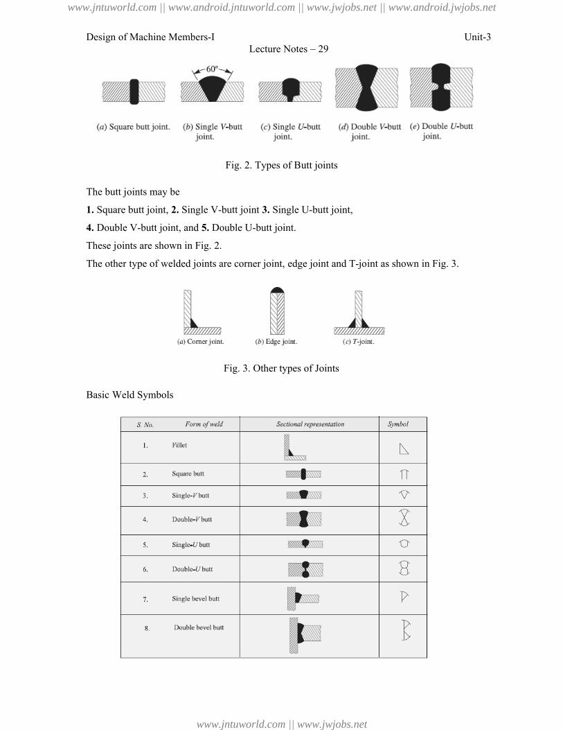
Design of Machine Members-I
The butt joints may be
1. Square butt joint, 2. Single V-butt joint
4. Double V-butt joint, and 5. Double U
These joints are shown in Fig. 2.
The other type of welded joints are corner joint, edge join
Basic Weld Symbols
Lecture Notes – 29
Fig. 2. Types of Butt joints
butt joint 3. Single U-butt joint,
Double U-butt joint.
The other type of welded joints are corner joint, edge joint and T-joint as shown in Fig. 3
Fig. 3. Other types of Joints
Unit-3
joint as shown in Fig. 3.
www.jntuworld.com || www.android.jntuworld.com || www.jwjobs.net || www.android.jwjobs.net
www.jntuworld.com || www.jwjobs.net
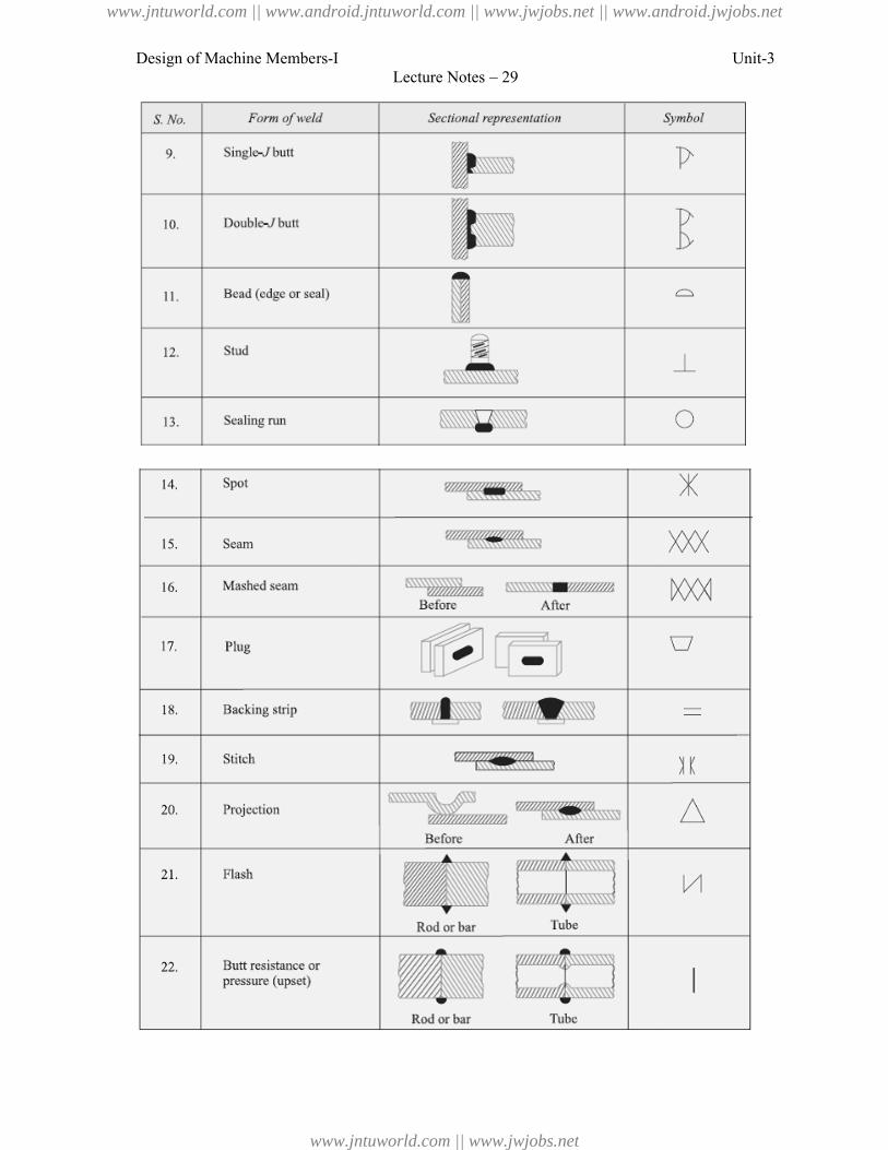
Design of Machine Members-ILecture Notes – 29
Unit-3
www.jntuworld.com || www.android.jntuworld.com || www.jwjobs.net || www.android.jwjobs.net
www.jntuworld.com || www.jwjobs.net
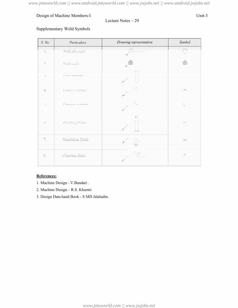
Design of Machine Members-I
Supplementary Weld Symbols
References:
1. Machine Design - V.Bandari .
2. Machine Design – R.S. Khurmi
3. Design Data hand Book - S MD Jalaludin
Lecture Notes – 29
S MD Jalaludin.
Unit-3
www.jntuworld.com || www.android.jntuworld.com || www.jwjobs.net || www.android.jwjobs.net
www.jntuworld.com || www.jwjobs.net
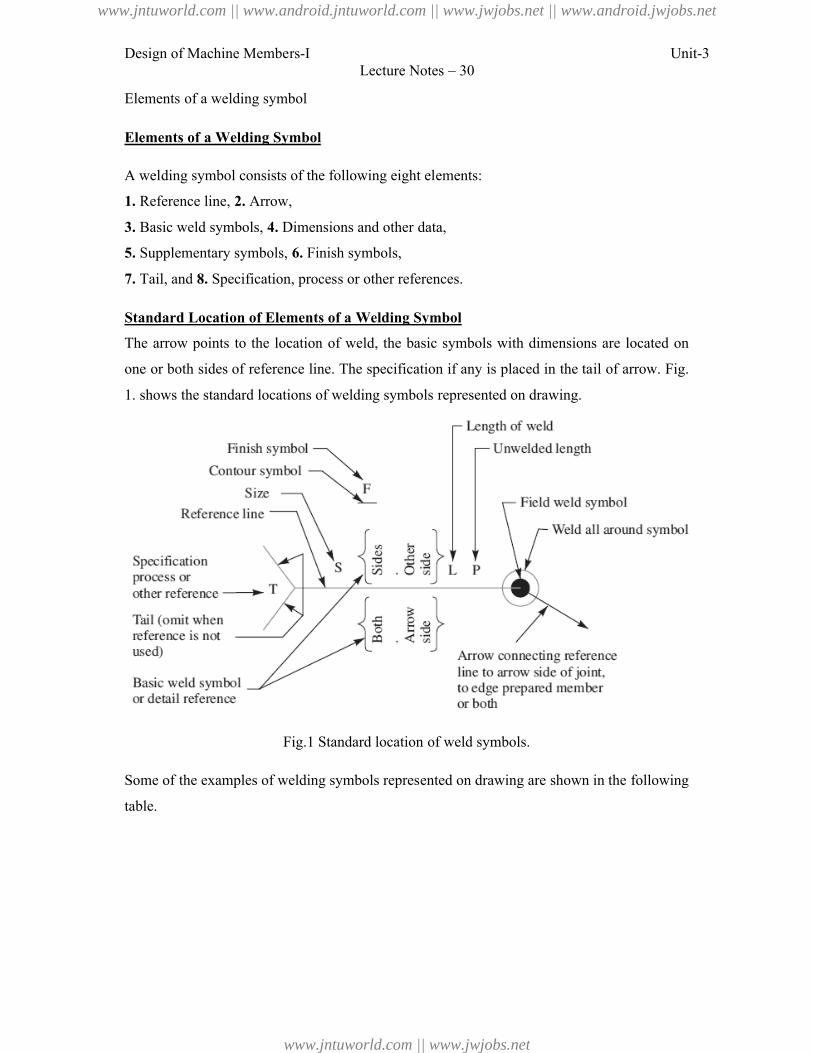
Design of Machine Members-I
Elements of a welding symbol
Elements of a Welding Symbol
A welding symbol consists of the following eight elements:
1. Reference line, 2. Arrow,
3. Basic weld symbols, 4. Dimensions and other data,
5. Supplementary symbols, 6. Finish symbols,
7. Tail, and 8. Specification, process or other references.
Standard Location of Elements of a Welding Symbol
The arrow points to the location of weld, the basic symbols with dimensions are located on
one or both sides of reference line. The specification if
1. shows the standard locations of welding symbols represented on drawing.
Fig.1 Standard location of weld symbols.
Some of the examples of welding symbols represented on drawing are shown in the following
table.
Lecture Notes – 30
Elements of a Welding Symbol
A welding symbol consists of the following eight elements:
Dimensions and other data,
Finish symbols,
Specification, process or other references.
Standard Location of Elements of a Welding Symbol
The arrow points to the location of weld, the basic symbols with dimensions are located on
or both sides of reference line. The specification if any is placed in the tail of arrow. Fig.
the standard locations of welding symbols represented on drawing.
Fig.1 Standard location of weld symbols.
Some of the examples of welding symbols represented on drawing are shown in the following
Unit-3
The arrow points to the location of weld, the basic symbols with dimensions are located on
in the tail of arrow. Fig.
Some of the examples of welding symbols represented on drawing are shown in the following
www.jntuworld.com || www.android.jntuworld.com || www.jwjobs.net || www.android.jwjobs.net
www.jntuworld.com || www.jwjobs.net
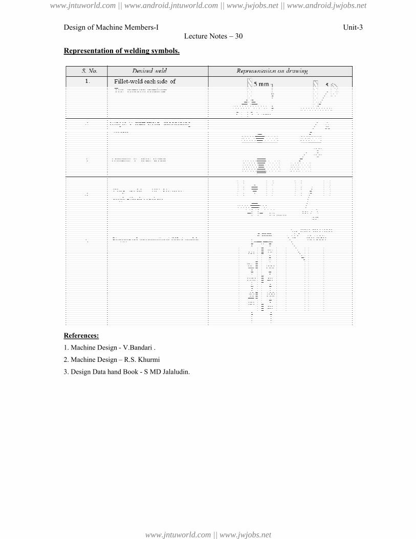
Design of Machine Members-I
Representation of welding symbols.
References:
1. Machine Design - V.Bandari .
2. Machine Design – R.S. Khurmi
3. Design Data hand Book - S MD Jalaludin.
Lecture Notes – 30
Representation of welding symbols.
S MD Jalaludin.
Unit-3
www.jntuworld.com || www.android.jntuworld.com || www.jwjobs.net || www.android.jwjobs.net
www.jntuworld.com || www.jwjobs.net
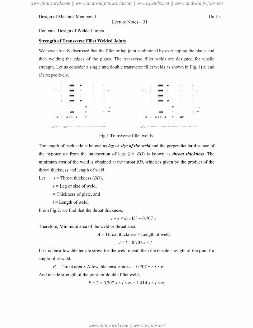
Design of Machine Members-I
Contents: Design of Welded Joints
Strength of Transverse Fillet Welded Joints
We have already discussed that the fillet or lap joint is obtained by overlapping the plates and
then welding the edges of the plates. The transverse fillet welds are designed
strength. Let us consider a single and double transverse fil
(b) respectively.
Fig.1 Transverse fillet welds.
The length of each side is known as
the hypotenuse from the intersection of legs (
minimum area of the weld is obtained at the throat
throat thickness and length of weld.
Let t = Throat thickness (BD
s = Leg or size of weld,
= Thickness of plate, and
l = Length of weld,
From Fig.2, we find that the throat thickness,
Therefore, Minimum area of the weld or throat area,
A
If σt is the allowable tensile stress for the weld
single fillet weld,
P = Throat area × Allowable tensile stress = 0.707
And tensile strength of the joint for double fillet weld,
P = 2 × 0.707
Lecture Notes – 31
Contents: Design of Welded Joints
Strength of Transverse Fillet Welded Joints
We have already discussed that the fillet or lap joint is obtained by overlapping the plates and
then welding the edges of the plates. The transverse fillet welds are designed
us consider a single and double transverse fillet welds as shown in Fig. 1
Fig.1 Transverse fillet welds.
The length of each side is known as leg or size of the weld and the perpendicular distance of
hypotenuse from the intersection of legs (i.e. BD) is known as throat thickness.
minimum area of the weld is obtained at the throat BD, which is given by the product of the
throat thickness and length of weld.
BD),
= Thickness of plate, and
, we find that the throat thickness,
t = s × sin 45° = 0.707 s
Minimum area of the weld or throat area,
A = Throat thickness × Length of weld
= t × l = 0.707 s × l
the allowable tensile stress for the weld metal, then the tensile strength of the joint for
= Throat area × Allowable tensile stress = 0.707 s × l × σt
nd tensile strength of the joint for double fillet weld,
= 2 × 0.707 s × l × σt = 1.414 s × l × σt
Unit-3
We have already discussed that the fillet or lap joint is obtained by overlapping the plates and
then welding the edges of the plates. The transverse fillet welds are designed for tensile
let welds as shown in Fig. 1(a) and
and the perpendicular distance of
throat thickness. The
by the product of the
metal, then the tensile strength of the joint for
www.jntuworld.com || www.android.jntuworld.com || www.jwjobs.net || www.android.jwjobs.net
www.jntuworld.com || www.jwjobs.net
Design of Machine Members-I
Note: Since the weld is weaker than the plate due to slag and blow holes, therefore the weld
is given a reinforcement which may be taken as 10% of the plate thickness.
Strength of Parallel Fillet Welded Joints
The parallel fillet welded joints are designed for shear strength. Consider a double parallel
fillet welded joint as shown in Fig.
that the minimum area of weld or the throat area,
If τ is the allowable shear stress for the weld metal, then the shear strength of the joint for
single parallel fillet weld,
P = Throat area × Allowable shear stress = 0.707
And shear strength of the joint for double parallel fillet weld,
P = 2 × 0.707 ×
Notes: 1. If there is a combination of single transverse and double parallel
shown in Fig. (b), then the strength of the joint is given by the sum of strengths of single
transverse and double parallel fillet welds.
P = 0.707
Where l1 is normally the width of the plate.
2. In order to allow for starting and stopping of the
length of each weld obtained by the above expression.
3. For reinforced fillet welds, the throat dimension
Problem:
A plate 100 mm wide and 10 mm thick is to be welded to another plate by means
parallel fillets. The plates are subjected to
the permissible shear stress in the weld does not exceed
Lecture Notes – 31
Since the weld is weaker than the plate due to slag and blow holes, therefore the weld
which may be taken as 10% of the plate thickness.
Strength of Parallel Fillet Welded Joints
welded joints are designed for shear strength. Consider a double parallel
welded joint as shown in Fig.3 (a). We have already discussed in the previous article,
minimum area of weld or the throat area,
A = 0.707 s × l
shear stress for the weld metal, then the shear strength of the joint for
= Throat area × Allowable shear stress = 0.707 s × l × τ
And shear strength of the joint for double parallel fillet weld,
= 2 × 0.707 × s × l × τ = 1.414 s × l × τ
Fig.3
. If there is a combination of single transverse and double parallel fillet welds as
then the strength of the joint is given by the sum of strengths of single
transverse and double parallel fillet welds. Mathematically,
= 0.707s × l1 × σt + 1.414 s × l2 × τ
is normally the width of the plate.
In order to allow for starting and stopping of the bead, 12.5 mm should be added to the
obtained by the above expression.
reinforced fillet welds, the throat dimension may be taken as 0.85 t.
10 mm thick is to be welded to another plate by means
parallel fillets. The plates are subjected to a static load of 80 kN. Find the length of
permissible shear stress in the weld does not exceed 55 MPa.
Unit-3
Since the weld is weaker than the plate due to slag and blow holes, therefore the weld
welded joints are designed for shear strength. Consider a double parallel
). We have already discussed in the previous article,
shear stress for the weld metal, then the shear strength of the joint for
fillet welds as
then the strength of the joint is given by the sum of strengths of single
bead, 12.5 mm should be added to the
10 mm thick is to be welded to another plate by means of double
a static load of 80 kN. Find the length of weld if
www.jntuworld.com || www.android.jntuworld.com || www.jwjobs.net || www.android.jwjobs.net
www.jntuworld.com || www.jwjobs.net
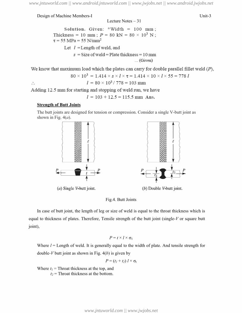
Design of Machine Members-I
Strength of Butt Joints
The butt joints are designed for tension or compression. Consider a single Vshown in Fig. 4(a).
In case of butt joint, the length of leg or size of weld is equal to the throat thickness which is
equal to thickness of plates. Therefore,
joint),
Where l = Length of weld. It is generally equal to the
double-V butt joint as shown in Fig.
Where t1 = Throat thickness at the top, andt2 = Throat thickness at the bottom.
Lecture Notes – 31
The butt joints are designed for tension or compression. Consider a single V-butt joint as
Fig.4. Butt Joints
the length of leg or size of weld is equal to the throat thickness which is
Therefore, Tensile strength of the butt joint (single-V or square butt
P = t × l × σ1
= Length of weld. It is generally equal to the width of plate. And tensile strength for
butt joint as shown in Fig. 4(b) is given by
P = (t1 + t2) l × σt
= Throat thickness at the top, and= Throat thickness at the bottom.
Unit-3
butt joint as
the length of leg or size of weld is equal to the throat thickness which is
or square butt
And tensile strength for
www.jntuworld.com || www.android.jntuworld.com || www.jwjobs.net || www.android.jwjobs.net
www.jntuworld.com || www.jwjobs.net
Design of Machine Members-I Unit-3Lecture Notes – 31
It may be noted that size of the weld should be greater than the thickness of the plate, but it
may be less. The following table shows recommended minimum size of the welds.
Stresses for Welded Joints
The stresses in welded joints are difficult to determine because of the variable and
unpredictable parameters like homogenuity of the weld metal, thermal stresses in the welds,
changes of physical properties due to high rate of cooling etc. The stresses are obtained, on
the following assumptions:
1. The load is distributed uniformly along the entire length of the weld, and
2. The stress is spread uniformly over its effective section.
The following table shows the stresses for welded joints for joining ferrous metals with mild
steel electrode under steady and fatigue or reversed load.
Stress Concentration Factor for Welded Joints
The reinforcement provided to the weld produces stress concentration at the junction of the
weld and the parent metal. When the parts are subjected to fatigue loading, the stress
concentration factors should be taken into account.
References:
1. Machine Design - V.Bandari .
2. Machine Design – R.S. Khurmi
3. Design Data hand Book - S MD Jalaludin.
www.jntuworld.com || www.android.jntuworld.com || www.jwjobs.net || www.android.jwjobs.net
www.jntuworld.com || www.jwjobs.net
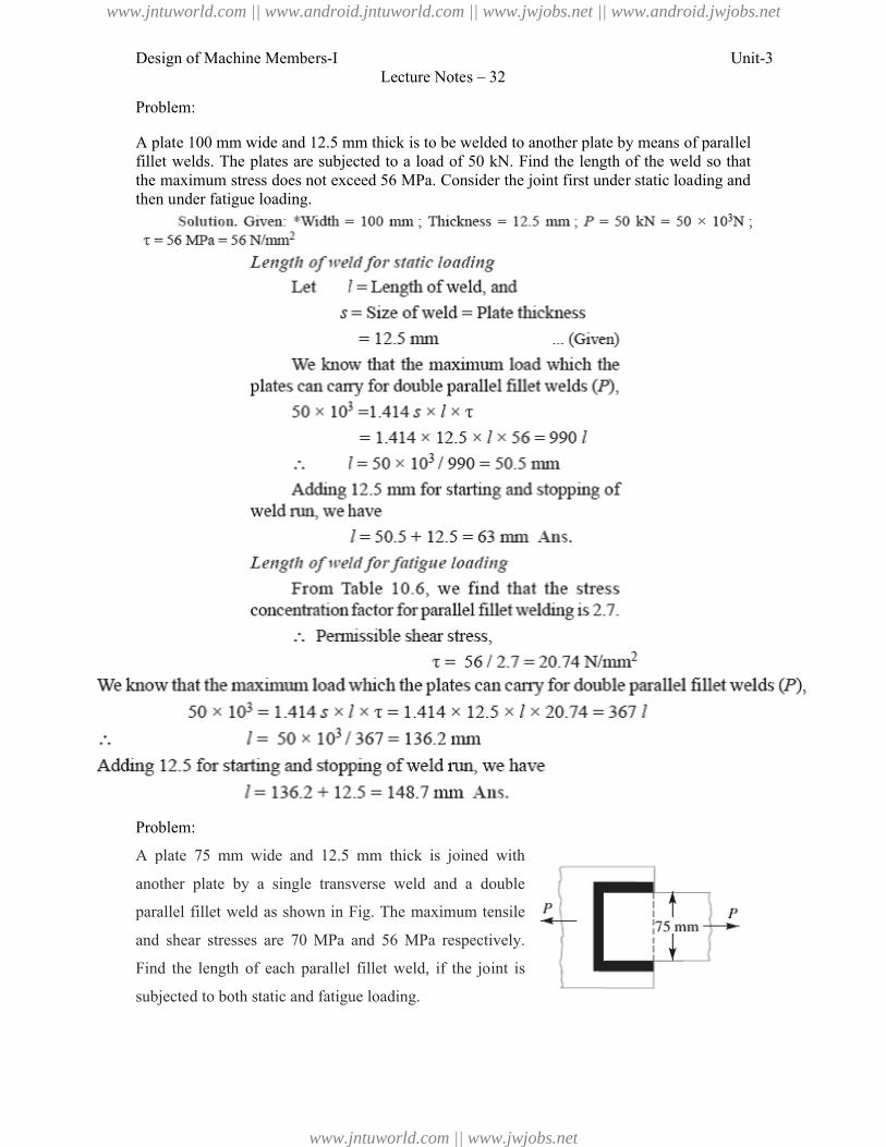
Design of Machine Members-I
Problem:
A plate 100 mm wide and 12.5 mm thick is to be welded to another plate byfillet welds. The plates are subjected to a load of 50 kN. Find the length of the weldthe maximum stress does not exceed 56 MPa. Consider the then under fatigue loading.
Problem:
A plate 75 mm wide and 12.5 mm thick is joined with
another plate by a single transverse weld and a double
parallel fillet weld as shown in Fig.
and shear stresses are 70 MPa and
Find the length of each parallel fillet weld, if the joint is
subjected to both static and fatigue loading.
Lecture Notes – 32
A plate 100 mm wide and 12.5 mm thick is to be welded to another plate by means of parallel fillet welds. The plates are subjected to a load of 50 kN. Find the length of the weldthe maximum stress does not exceed 56 MPa. Consider the joint first under static loading and
A plate 75 mm wide and 12.5 mm thick is joined with
transverse weld and a double
parallel fillet weld as shown in Fig. The maximum tensile
stresses are 70 MPa and 56 MPa respectively.
Find the length of each parallel fillet weld, if the joint is
subjected to both static and fatigue loading.
Unit-3
means of parallel fillet welds. The plates are subjected to a load of 50 kN. Find the length of the weld so that
joint first under static loading and
www.jntuworld.com || www.android.jntuworld.com || www.jwjobs.net || www.android.jwjobs.net
www.jntuworld.com || www.jwjobs.net
Design of Machine Members-I
References:
1. Machine Design - V.Bandari .
2. Machine Design – R.S. Khurmi
3. Design Data hand Book - S MD Jalaludin
Lecture Notes – 32
V.Bandari .
R.S. Khurmi
S MD Jalaludin.
Unit-3
www.jntuworld.com || www.android.jntuworld.com || www.jwjobs.net || www.android.jwjobs.net
www.jntuworld.com || www.jwjobs.net
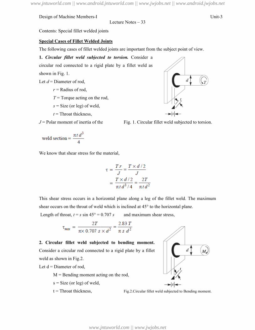
Design of Machine Members-I
Contents: Special fillet welded joints
Special Cases of Fillet Welded Joints
The following cases of fillet welded joints are important from the subject point of view.
1. Circular fillet weld subjected to torsion.
circular rod connected to a rigid plate
shown in Fig. 1.
Let d = Diameter of rod,
r = Radius of rod,
T = Torque acting on the rod,
s = Size (or leg) of weld,
t = Throat thickness,
J = Polar moment of inertia of the
We know that shear stress for the material,
This shear stress occurs in a horizontal plane along a leg of the fillet weld. The maximum
shear occurs on the throat of weld which is inclined at 45° to the horizontal plane.
Length of throat, t = s sin 45° = 0.707
2. Circular fillet weld subjected to bending moment.
Consider a circular rod connected to a
weld as shown in Fig.2.
Let d = Diameter of rod,
M = Bending moment acting on the rod,
s = Size (or leg) of weld,
t = Throat thickness,
Lecture Notes – 33
Contents: Special fillet welded joints
Special Cases of Fillet Welded Joints
The following cases of fillet welded joints are important from the subject point of view.
Circular fillet weld subjected to torsion. Consider a
rigid plate by a fillet weld as
= Torque acting on the rod,
= Polar moment of inertia of the Fig. 1. Circular fillet weld subjected to tors
We know that shear stress for the material,
This shear stress occurs in a horizontal plane along a leg of the fillet weld. The maximum
occurs on the throat of weld which is inclined at 45° to the horizontal plane.
sin 45° = 0.707 s and maximum shear stress,
Circular fillet weld subjected to bending moment.
Consider a circular rod connected to a rigid plate by a fillet
= Bending moment acting on the rod,
Fig.2.Circular fillet weld subjected to Bending moment.
Unit-3
The following cases of fillet welded joints are important from the subject point of view.
Fig. 1. Circular fillet weld subjected to torsion.
This shear stress occurs in a horizontal plane along a leg of the fillet weld. The maximum
occurs on the throat of weld which is inclined at 45° to the horizontal plane.
Fig.2.Circular fillet weld subjected to Bending moment.
www.jntuworld.com || www.android.jntuworld.com || www.jwjobs.net || www.android.jwjobs.net
www.jntuworld.com || www.jwjobs.net
Design of Machine Members-I Unit-3Lecture Notes – 33
Z = Section modulus of the weld section
We know that the bending stress
This bending stress occurs in a horizontal plane along a leg of the fillet weld. The maximum
bending stress occurs on the throat of the weld which is inclined at 45° to the horizontal
plane.
Length of throat, t = s sin 45° = 0.707 s and maximum bending stress,
3. Long fillet weld subjected to torsion. Consider a vertical plate attached to a horizontal
plate by two identical fillet welds as shown in Fig.3.
Let T = Torque acting on the vertical plate,
l = Length of weld,
s = Size (or leg) of weld,
t = Throat thickness, and
J = Polar moment of inertia of the weld section
It may be noted that the effect of the applied torque is to rotate the vertical plate about the Z-
axis through its mid point. This rotation is resisted by shearing stresses developed between
two fillet welds and the horizontal plate. It is assumed that these horizontal shearing stresses
vary from zero at the Z-axis and maximum at the ends of the plate. This variation of shearing
stress is analogous to the variation of normal stress over the depth (l) of a beam subjected to
pure bending.
Therefore, Shear stress,
www.jntuworld.com || www.android.jntuworld.com || www.jwjobs.net || www.android.jwjobs.net
www.jntuworld.com || www.jwjobs.net
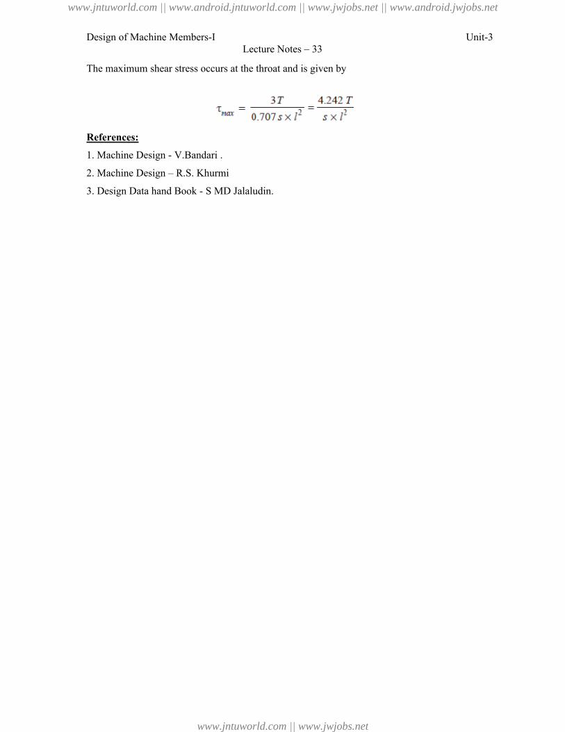
Design of Machine Members-I Unit-3Lecture Notes – 33
The maximum shear stress occurs at the throat and is given by
References:
1. Machine Design - V.Bandari .
2. Machine Design – R.S. Khurmi
3. Design Data hand Book - S MD Jalaludin.
www.jntuworld.com || www.android.jntuworld.com || www.jwjobs.net || www.android.jwjobs.net
www.jntuworld.com || www.jwjobs.net
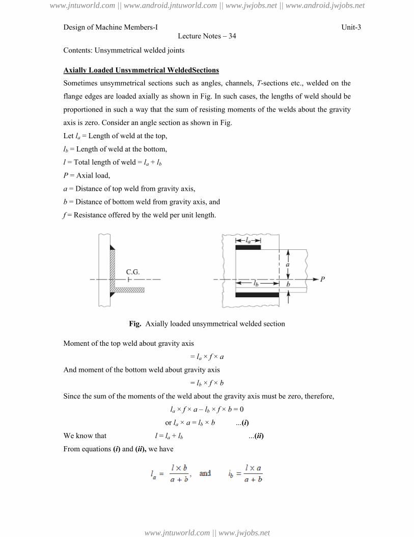
Design of Machine Members-I
Contents: Unsymmetrical welded joints
Axially Loaded Unsymmetrical WeldedSections
Sometimes unsymmetrical sections such as angles,
flange edges are loaded axially as shown in Fig.
proportioned in such a way that the sum of resisting
axis is zero. Consider an angle section as shown in Fig.
Let la = Length of weld at the top,
lb = Length of weld at the bottom,
l = Total length of weld = la + lb
P = Axial load,
a = Distance of top weld from gravity axis,
b = Distance of bottom weld from gravity axis, and
f = Resistance offered by the weld per unit length.
Fig. Axially loaded unsymmetrical welded section
Moment of the top weld about gravity axis
And moment of the bottom weld about gravity axis
Since the sum of the moments of the weld about the gravity axis must be zero, therefore,
We know that l =
From equations (i) and (ii), we have
Lecture Notes – 34
Contents: Unsymmetrical welded joints
Axially Loaded Unsymmetrical WeldedSections
Sometimes unsymmetrical sections such as angles, channels, T-sections etc., welded on the
axially as shown in Fig. In such cases, the lengths of weld
proportioned in such a way that the sum of resisting moments of the welds about the gravity
section as shown in Fig.
= Length of weld at the top,
= Length of weld at the bottom,
= Distance of top weld from gravity axis,
= Distance of bottom weld from gravity axis, and
= Resistance offered by the weld per unit length.
Axially loaded unsymmetrical welded section
gravity axis
= la × f × a
nd moment of the bottom weld about gravity axis
= lb × f × b
Since the sum of the moments of the weld about the gravity axis must be zero, therefore,
la × f × a – lb × f × b = 0
or la × a = lb × b ...(i)
= la + lb ...(ii)
we have
Unit-3
sections etc., welded on the
In such cases, the lengths of weld should be
moments of the welds about the gravity
Since the sum of the moments of the weld about the gravity axis must be zero, therefore,
www.jntuworld.com || www.android.jntuworld.com || www.jwjobs.net || www.android.jwjobs.net
www.jntuworld.com || www.jwjobs.net

Design of Machine Members-I Unit-3Lecture Notes – 34
References:
1. Machine Design - V.Bandari .
2. Machine Design – R.S. Khurmi
3. Design Data hand Book - S MD Jalaludin.
www.jntuworld.com || www.android.jntuworld.com || www.jwjobs.net || www.android.jwjobs.net
www.jntuworld.com || www.jwjobs.net
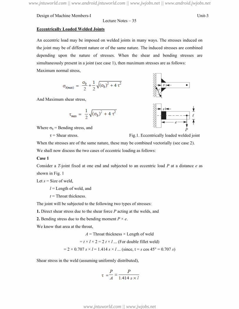
Design of Machine Members-I
Eccentrically Loaded Welded Joints
An eccentric load may be imposed on welded joints in many ways. The stresses induced on
the joint may be of different nature or of the same nature. The induced stresses are combined
depending upon the nature of stresses.
simultaneously present in a joint
Maximum normal stress,
And Maximum shear stress,
Where σb = Bending stress, and
τ = Shear stress.
When the stresses are of the same nature, these may be combined
We shall now discuss the two cases of eccentric loading as follows:
Case 1
Consider a T-joint fixed at one end and subjected to an eccentric load
shown in Fig. 1
Let s = Size of weld,
l = Length of weld, and
t = Throat thickness.
The joint will be subjected to the following two types of stresses:
1. Direct shear stress due to the shear force
2. Bending stress due to the bending moment
We know that area at the throat,
A = Throat thickness × Length of weld
= t × l × 2 = 2
= 2 × 0.707 s × l = 1.414
Shear stress in the weld (assuming uniformly distributed),
Lecture Notes – 35
Eccentrically Loaded Welded Joints
An eccentric load may be imposed on welded joints in many ways. The stresses induced on
joint may be of different nature or of the same nature. The induced stresses are combined
upon the nature of stresses. When the shear and bending stresses are
(see case 1), then maximum stresses are as follows:
Fig.1. Eccentrically loaded welded joint
When the stresses are of the same nature, these may be combined vectorially (see case 2).
We shall now discuss the two cases of eccentric loading as follows:
joint fixed at one end and subjected to an eccentric load P at a distance
The joint will be subjected to the following two types of stresses:
Direct shear stress due to the shear force P acting at the welds, and
stress due to the bending moment P × e.
= Throat thickness × Length of weld
× 2 = 2 t × l ... (For double fillet weld)
= 1.414 s × l ... (since, t = s cos 45° = 0.707 s)
(assuming uniformly distributed),
Unit-3
An eccentric load may be imposed on welded joints in many ways. The stresses induced on
joint may be of different nature or of the same nature. The induced stresses are combined
When the shear and bending stresses are
(see case 1), then maximum stresses are as follows:
oaded welded joint
vectorially (see case 2).
at a distance e as
www.jntuworld.com || www.android.jntuworld.com || www.jwjobs.net || www.android.jwjobs.net
www.jntuworld.com || www.jwjobs.net
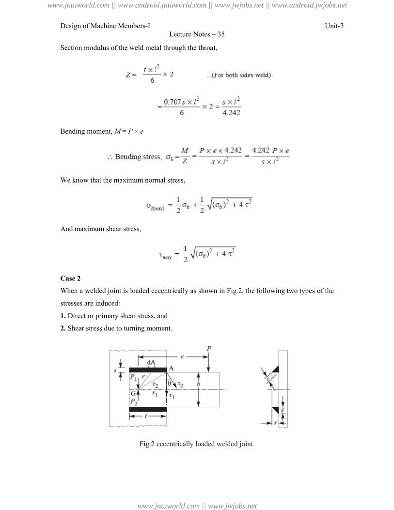
Design of Machine Members-I
Section modulus of the weld metal through the throat,
Bending moment, M = P × e
We know that the maximum normal stress,
And maximum shear stress,
Case 2
When a welded joint is loaded eccentrically
stresses are induced:
1. Direct or primary shear stress, and
2. Shear stress due to turning moment.
Fig.2
Lecture Notes – 35
Section modulus of the weld metal through the throat,
We know that the maximum normal stress,
When a welded joint is loaded eccentrically as shown in Fig.2, the following two types of the
Direct or primary shear stress, and
Shear stress due to turning moment.
Fig.2 eccentrically loaded welded joint.
Unit-3
the following two types of the
www.jntuworld.com || www.android.jntuworld.com || www.jwjobs.net || www.android.jwjobs.net
www.jntuworld.com || www.jwjobs.net
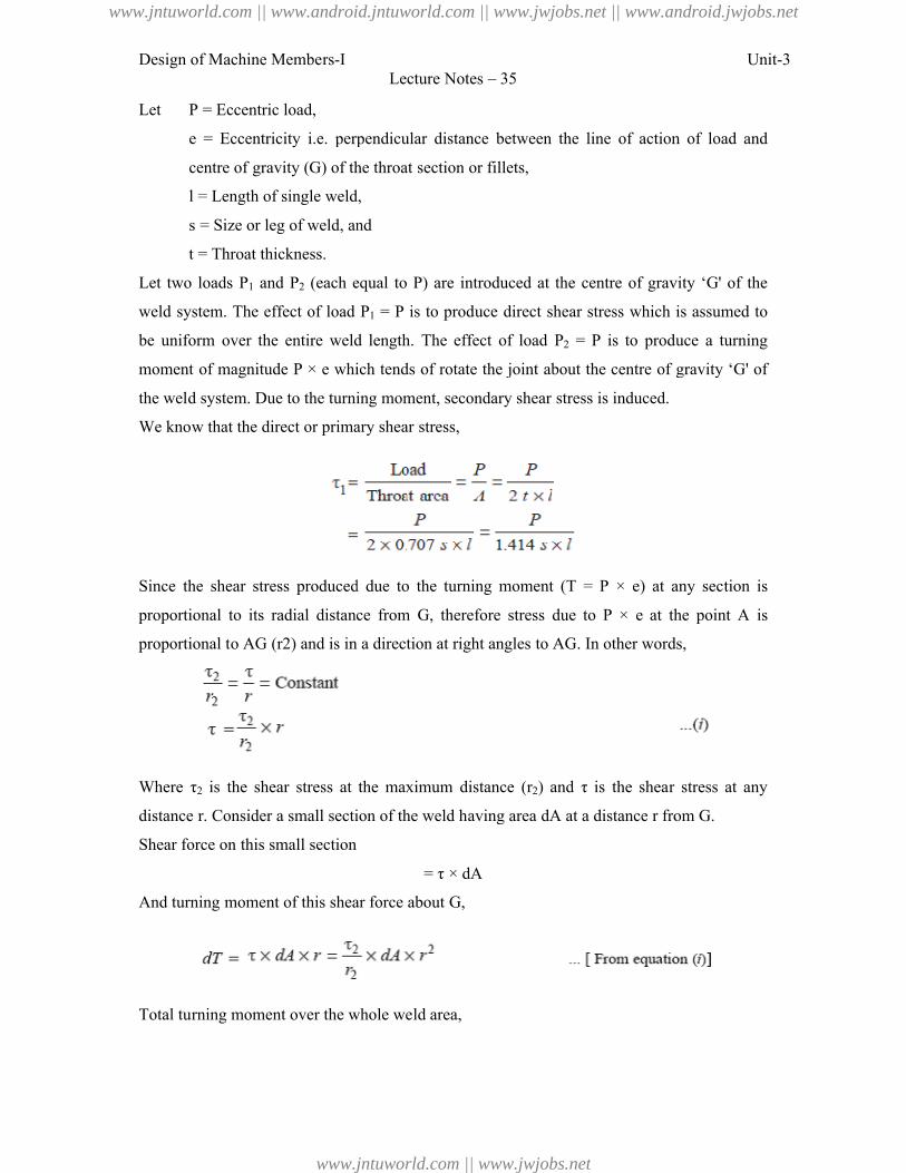
Design of Machine Members-I
Let P = Eccentric load,
e = Eccentricity i.e. perpendicular distance
centre of gravity (G) of the throat section
l = Length of single weld,
s = Size or leg of weld, and
t = Throat thickness.
Let two loads P1 and P2 (each equal to
weld system. The effect of load
be uniform over the entire weld length. The effect of load
moment of magnitude P × e which tends of rotate the joint about
the weld system. Due to the turning
We know that the direct or primary shear stress,
Since the shear stress produced due to the turning moment (
proportional to its radial distance from
proportional to AG (r2) and is in a direction at right angles to
Where τ2 is the shear stress at the maximum distance (
distance r. Consider a small section of the weld having area
Shear force on this small section
And turning moment of this shear force about
Total turning moment over the whole weld
Lecture Notes – 35
. perpendicular distance between the line of action of
) of the throat section or fillets,
= Length of single weld,
= Size or leg of weld, and
(each equal to P) are introduced at the centre of gravity ‘
system. The effect of load P1 = P is to produce direct shear stress which is assumed to
the entire weld length. The effect of load P2 = P is to produce a turning
which tends of rotate the joint about the centre of gravity ‘
the weld system. Due to the turning moment, secondary shear stress is induced.
We know that the direct or primary shear stress,
Since the shear stress produced due to the turning moment (T = P × e) at any section is
to its radial distance from G, therefore stress due to P × e at the point
is in a direction at right angles to AG. In other words,
is the shear stress at the maximum distance (r2) and τ is the shear stress at any
Consider a small section of the weld having area dA at a distance r from
= τ × dA
And turning moment of this shear force about G,
Total turning moment over the whole weld area,
Unit-3
between the line of action of load and
) are introduced at the centre of gravity ‘G' of the
is to produce direct shear stress which is assumed to
is to produce a turning
the centre of gravity ‘G' of
) at any section is
at the point A is
. In other words,
) and τ is the shear stress at any
from G.
www.jntuworld.com || www.android.jntuworld.com || www.jwjobs.net || www.android.jwjobs.net
www.jntuworld.com || www.jwjobs.net
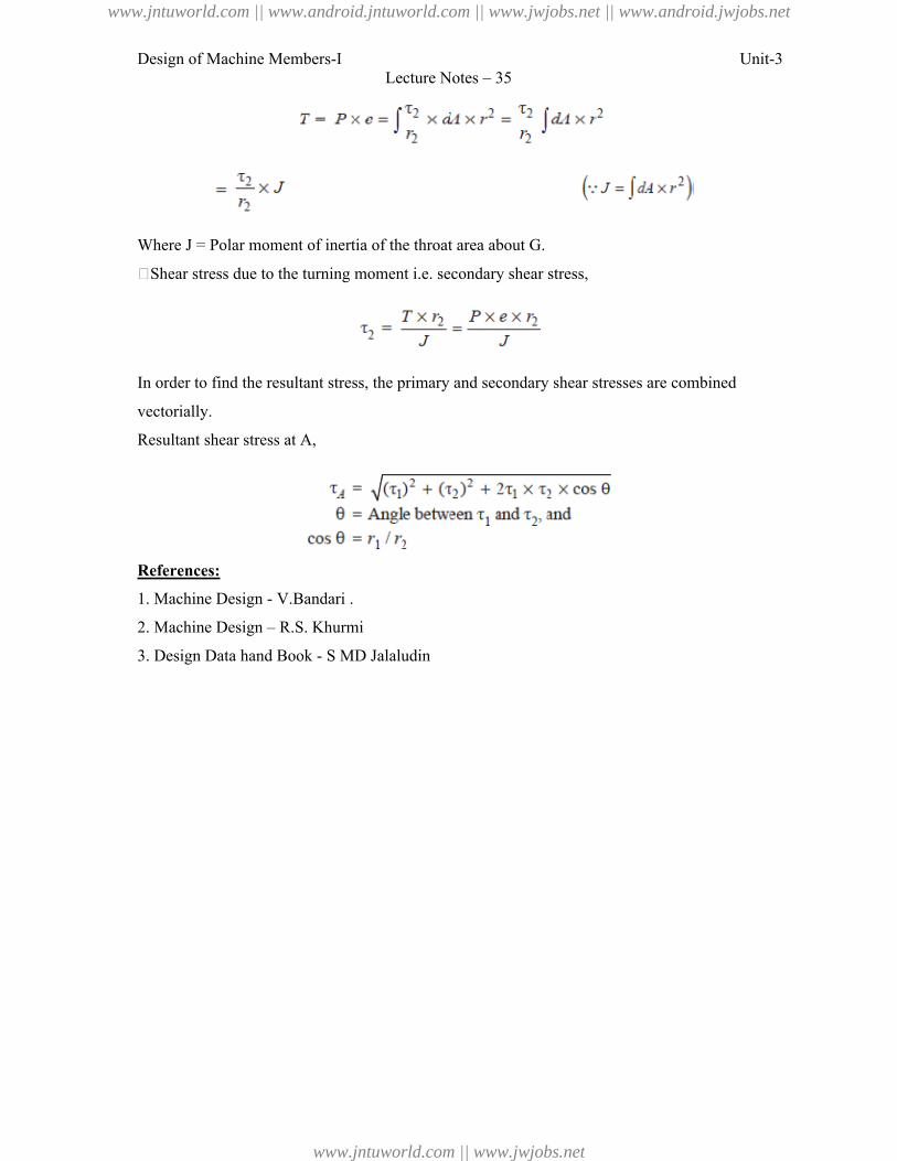
Design of Machine Members-I Unit-3Lecture Notes – 35
Where J = Polar moment of inertia of the throat area about G.
�Shear stress due to the turning moment i.e. secondary shear stress,
In order to find the resultant stress, the primary and secondary shear stresses are combined
vectorially.
Resultant shear stress at A,
References:
1. Machine Design - V.Bandari .
2. Machine Design – R.S. Khurmi
3. Design Data hand Book - S MD Jalaludin
www.jntuworld.com || www.android.jntuworld.com || www.jwjobs.net || www.android.jwjobs.net
www.jntuworld.com || www.jwjobs.net
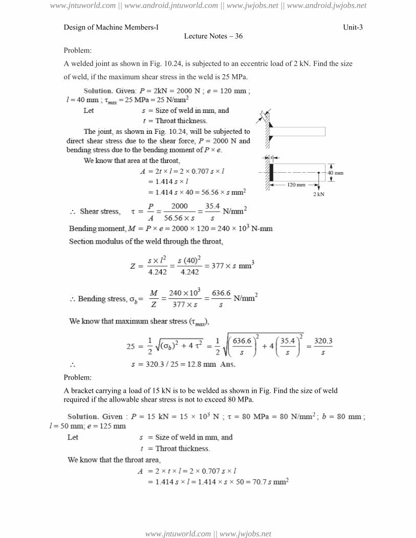
Design of Machine Members-I
Problem:
A welded joint as shown in Fig. 10.24, is subjected to an eccentric load of 2 kN.
of weld, if the maximum shear stress in the weld
Problem:
A bracket carrying a load of 15 kN is to required if the allowable shear stress is not to exceed 80 MPa.
Lecture Notes – 36
A welded joint as shown in Fig. 10.24, is subjected to an eccentric load of 2 kN.
of weld, if the maximum shear stress in the weld is 25 MPa.
A bracket carrying a load of 15 kN is to be welded as shown in Fig. Find the size of weld required if the allowable shear stress is not to exceed 80 MPa.
Unit-3
A welded joint as shown in Fig. 10.24, is subjected to an eccentric load of 2 kN. Find the size
the size of weld
www.jntuworld.com || www.android.jntuworld.com || www.jwjobs.net || www.android.jwjobs.net
www.jntuworld.com || www.jwjobs.net
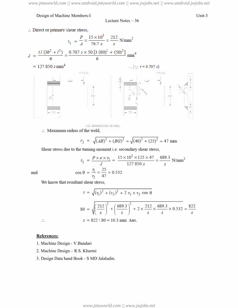
Design of Machine Members-I
References:
1. Machine Design - V.Bandari
2. Machine Design – R.S. Khurmi
3. Design Data hand Book - S MD Jalaludin.
Lecture Notes – 36
R.S. Khurmi
S MD Jalaludin.
Unit-3
www.jntuworld.com || www.android.jntuworld.com || www.jwjobs.net || www.android.jwjobs.net
www.jntuworld.com || www.jwjobs.net
Design of Machine Members-I Unit-4Lecture Notes – 37
Introduction to Screwed Joints:
A screw thread is formed by cutting a continuous helical groove on a cylindrical
surface. A screw made by cutting a single helical groove on the cylinder is known as single
threaded (or single-start) screw and if a second thread is cut in the space between the
grooves of the first, a double threaded (or double-start) screw is formed. Similarly, triple
and quadruple (i.e. multiple-start) threads may be formed. The helical grooves may be cut
either right hand or left hand.
A screwed joint is mainly composed of two elements i.e. a bolt and nut. The screwed
joints are widely used where the machine parts are required to be readily connected or
disconnected without damage to the machine or the fastening. This may be for the purpose of
holding or adjustment in assembly or service inspection, repair, or replacement or it may be
for the manufacturing or assembly reasons. The parts may be rigidly connected or provisions
may be made for predetermined relative motion.
Advantages and Disadvantages of Screwed Joints
Following are the advantages and disadvantages of the screwed joints.
Advantages
1. Screwed joints are highly reliable in operation.
2. Screwed joints are convenient to assemble and disassemble.
3. A wide range of screwed joints may be adapted to various operating conditions.
4. Screws are relatively cheap to produce due to standardization and highly efficient
manufacturing processes.
Disadvantages
The main disadvantage of the screwed joints is the stress concentration in the threaded
portions which are vulnerable points under variable load conditions.
Note : The strength of the screwed joints is not comparable with that of riveted or welded
joints.
Important Terms Used in Screw Threads
The following terms used in screw threads, as shown in Fig. 1, are important from the subject
point of view:
www.jntuworld.com || www.android.jntuworld.com || www.jwjobs.net || www.android.jwjobs.net
www.jntuworld.com || www.jwjobs.net
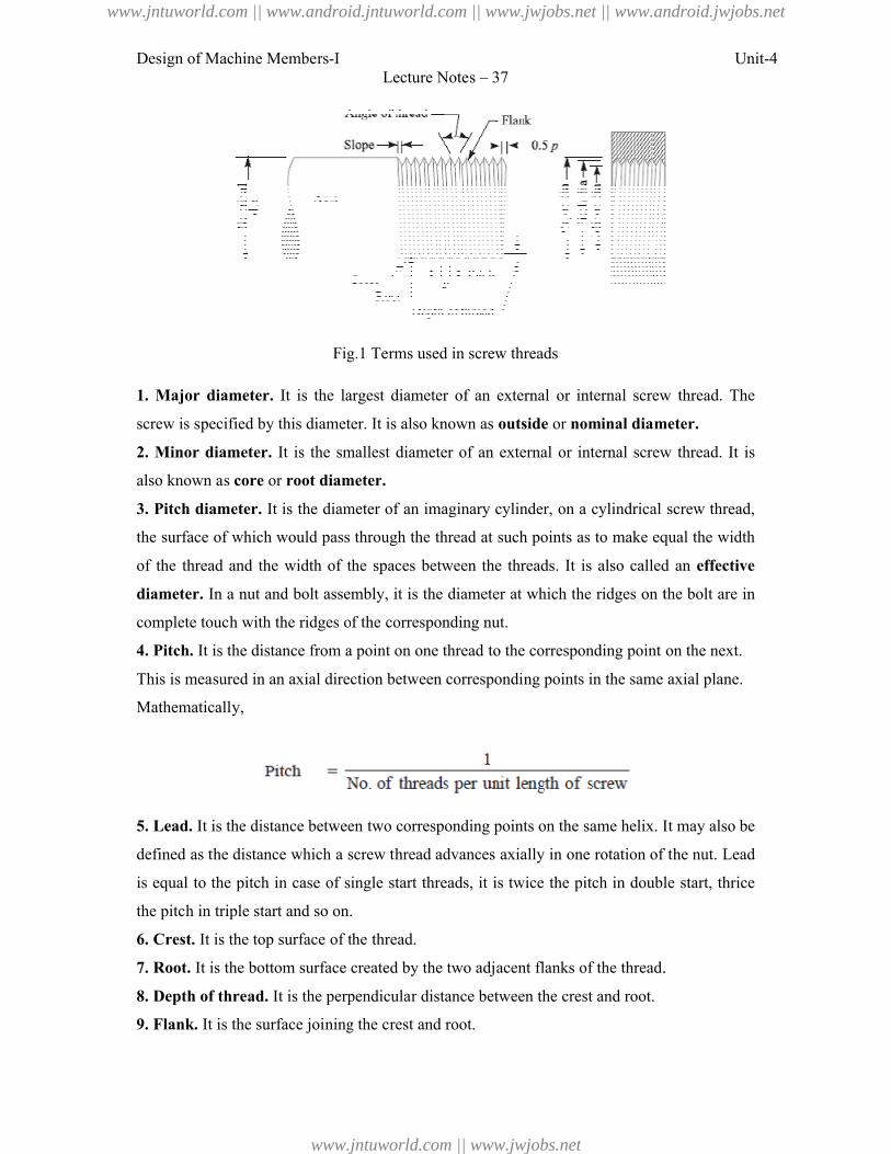
Design of Machine Members-I
Fig.1 Terms used in screw threads
1. Major diameter. It is the largest diameter of an external or internal screw thread. The
screw is specified by this diameter. It is also known
2. Minor diameter. It is the smallest diameter of an external or internal screw thread. It is
also known as core or root diameter
3. Pitch diameter. It is the diameter of an imaginary cylinder, on a cylindrical screw thread
the surface of which would pass through the thread at such points as to make equal the width
of the thread and the width of the spaces between the threads. It is also called an
diameter. In a nut and bolt assembly, it is the diameter at which t
complete touch with the ridges of the corresponding nut.
4. Pitch. It is the distance from a point on one thread to the corresponding point on the next.
This is measured in an axial direction between corresponding points in the
Mathematically,
5. Lead. It is the distance between two corresponding points on the same helix. It may also
defined as the distance which a screw thread advances axially in one rotation of the nut. Lead
is equal to the pitch in case of single start threads, it is twice the pitch in double start, thrice
the pitch in triple start and so on.
6. Crest. It is the top surface of the thread.
7. Root. It is the bottom surface created by the two adjacent flanks of the thread.
8. Depth of thread. It is the perpendicular distance between the crest and root.
9. Flank. It is the surface joining the crest and root.
Lecture Notes – 37
Fig.1 Terms used in screw threads
It is the largest diameter of an external or internal screw thread. The
screw is specified by this diameter. It is also known as outside or nominal diameter
It is the smallest diameter of an external or internal screw thread. It is
root diameter.
It is the diameter of an imaginary cylinder, on a cylindrical screw thread
the surface of which would pass through the thread at such points as to make equal the width
thread and the width of the spaces between the threads. It is also called an
and bolt assembly, it is the diameter at which the ridges on the bolt are in
ridges of the corresponding nut.
It is the distance from a point on one thread to the corresponding point on the next.
This is measured in an axial direction between corresponding points in the same axial plane.
It is the distance between two corresponding points on the same helix. It may also
defined as the distance which a screw thread advances axially in one rotation of the nut. Lead
of single start threads, it is twice the pitch in double start, thrice
triple start and so on.
It is the top surface of the thread.
It is the bottom surface created by the two adjacent flanks of the thread.
It is the perpendicular distance between the crest and root.
It is the surface joining the crest and root.
Unit-4
It is the largest diameter of an external or internal screw thread. The
nominal diameter.
It is the smallest diameter of an external or internal screw thread. It is
It is the diameter of an imaginary cylinder, on a cylindrical screw thread,
the surface of which would pass through the thread at such points as to make equal the width
thread and the width of the spaces between the threads. It is also called an effective
he ridges on the bolt are in
It is the distance from a point on one thread to the corresponding point on the next.
same axial plane.
It is the distance between two corresponding points on the same helix. It may also be
defined as the distance which a screw thread advances axially in one rotation of the nut. Lead
of single start threads, it is twice the pitch in double start, thrice
It is the bottom surface created by the two adjacent flanks of the thread.
www.jntuworld.com || www.android.jntuworld.com || www.jwjobs.net || www.android.jwjobs.net
www.jntuworld.com || www.jwjobs.net
Design of Machine Members-I Unit-4Lecture Notes – 37
10. Angle of thread. It is the angle included by the flanks of the thread.
11. Slope. It is half the pitch of the thread.
References:
1. Machine Design - V.Bandari .
2. Machine Design – R.S. Khurmi
3. Design Data hand Book - S MD Jalaludin.
www.jntuworld.com || www.android.jntuworld.com || www.jwjobs.net || www.android.jwjobs.net
www.jntuworld.com || www.jwjobs.net
Design of Machine Members-I Unit-4Lecture Notes – 39
Stresses in Screwed Fastening due to Static Loading
The following stresses in screwed fastening due to static loading are important from the
subject point of view:
1. Internal stresses due to screwing up forces,
2. Stresses due to external forces, and
3. Stress due to combination of stresses at (1) and (2).
Initial Stresses due to Screwing up Forces
The following stresses are induced in a bolt, screw or stud when it is screwed up tightly.
1. Tensile stress due to stretching of bolt. Since none of the above mentioned stresses are
accurately determined, therefore bolts are designed on the basis of direct tensile stress with a
large factor of safety in order to account for the indeterminate stresses. The initial tension in a
bolt, based on experiments, may be found by the relation
Pi = 2840 d N
Where Pi = Initial tension in a bolt, and
d = Nominal diameter of bolt, in mm.
The above relation is used for making a joint fluid tight like steam engine cylinder cover
joints etc. When the joint is not required as tight as fluid-tight joint, then the initial tension in
a bolt may be reduced to half of the above value. In such cases
Pi = 1420 d N
The small diameter bolts may fail during tightening, therefore bolts of smaller diameter (less
than M 16 or M 18) are not permitted in making fluid tight joints. If the bolt is not initially
stressed, then the maximum safe axial load which may be applied to it, is given by
P = Permissible stress × Cross-sectional area at bottom of the thread
Where dp = Pitch diameter, and
dc = Core or minor diameter.
Stresses due to External Forces
The following stresses are induced in a bolt when it is subjected to an external load.
1. Tensile stress. The bolts, studs and screws usually carry a load in the direction of the bolt
axis which induces a tensile stress in the bolt.
Let dc = Root or core diameter of the thread, and
www.jntuworld.com || www.android.jntuworld.com || www.jwjobs.net || www.android.jwjobs.net
www.jntuworld.com || www.jwjobs.net
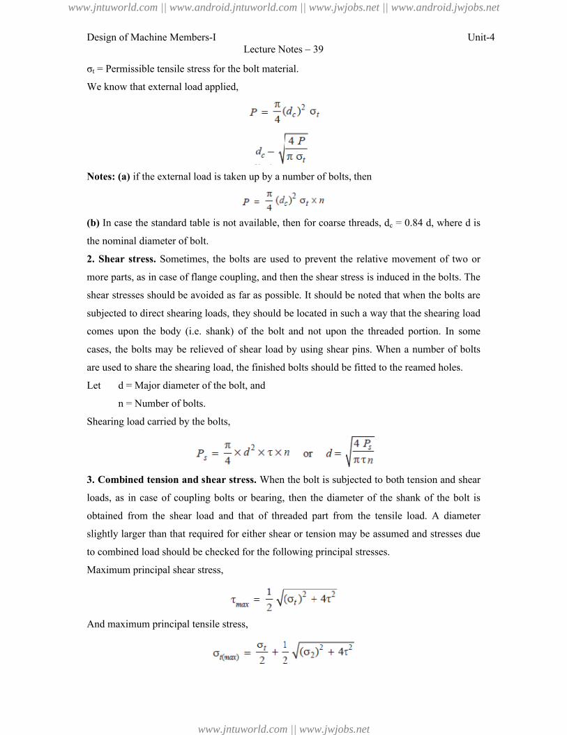
Design of Machine Members-I Unit-4Lecture Notes – 39
σt = Permissible tensile stress for the bolt material.
We know that external load applied,
Notes: (a) if the external load is taken up by a number of bolts, then
(b) In case the standard table is not available, then for coarse threads, dc = 0.84 d, where d is
the nominal diameter of bolt.
2. Shear stress. Sometimes, the bolts are used to prevent the relative movement of two or
more parts, as in case of flange coupling, and then the shear stress is induced in the bolts. The
shear stresses should be avoided as far as possible. It should be noted that when the bolts are
subjected to direct shearing loads, they should be located in such a way that the shearing load
comes upon the body (i.e. shank) of the bolt and not upon the threaded portion. In some
cases, the bolts may be relieved of shear load by using shear pins. When a number of bolts
are used to share the shearing load, the finished bolts should be fitted to the reamed holes.
Let d = Major diameter of the bolt, and
n = Number of bolts.
Shearing load carried by the bolts,
3. Combined tension and shear stress. When the bolt is subjected to both tension and shear
loads, as in case of coupling bolts or bearing, then the diameter of the shank of the bolt is
obtained from the shear load and that of threaded part from the tensile load. A diameter
slightly larger than that required for either shear or tension may be assumed and stresses due
to combined load should be checked for the following principal stresses.
Maximum principal shear stress,
And maximum principal tensile stress,
www.jntuworld.com || www.android.jntuworld.com || www.jwjobs.net || www.android.jwjobs.net
www.jntuworld.com || www.jwjobs.net
Design of Machine Members-I Unit-4Lecture Notes – 39
These stresses should not exceed the safe permissible values of stresses.
References:
1. Machine Design - V.Bandari .
2. Machine Design – R.S. Khurmi
3. Design Data hand Book - S MD Jalaludin.
www.jntuworld.com || www.android.jntuworld.com || www.jwjobs.net || www.android.jwjobs.net
www.jntuworld.com || www.jwjobs.net
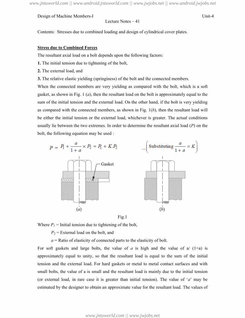
Design of Machine Members-I
Contents: Stresses due to combined loading and design of cylindrical cover plates.
Stress due to Combined Forces
The resultant axial load on a bolt depends upon the following
1. The initial tension due to tightening of the bolt,
2. The external load, and
3. The relative elastic yielding (springiness) of the bolt and the connected members.
When the connected members are very yielding as compared with the bolt, which is a soft
gasket, as shown in Fig. 1 (a), then the resultant load on the bolt is
sum of the initial tension and the external load. On the other hand, if the bolt is very yielding
as compared with the connected members, as shown in Fig.
be either the initial tension or the ex
usually lie between the two extremes. In order to determine the resultant axial load (
bolt, the following equation may be used :
Where P1 = Initial tension due to tightening of th
P2 = External load on the bolt, and
a = Ratio of elasticity of connected parts to the elasticity of bolt.
For soft gaskets and large bolts, the value of
approximately equal to unity, so that the resultant load
tension and the external load. For hard gaskets or metal to metal contact surfaces and with
small bolts, the value of a is small
(or external load, in rare case it is greater than
estimated by the designer to obtain an approximate value for the
Lecture Notes – 41
Contents: Stresses due to combined loading and design of cylindrical cover plates.
Stress due to Combined Forces
The resultant axial load on a bolt depends upon the following factors:
The initial tension due to tightening of the bolt,
The relative elastic yielding (springiness) of the bolt and the connected members.
When the connected members are very yielding as compared with the bolt, which is a soft
), then the resultant load on the bolt is approximately equal to the
sum of the initial tension and the external load. On the other hand, if the bolt is very yielding
compared with the connected members, as shown in Fig. 1(b), then the resultant load will
either the initial tension or the external load, whichever is greater. The actual conditions
between the two extremes. In order to determine the resultant axial load (
equation may be used :
Fig.1
= Initial tension due to tightening of the bolt,
= External load on the bolt, and
= Ratio of elasticity of connected parts to the elasticity of bolt.
For soft gaskets and large bolts, the value of a is high and the value of
equal to unity, so that the resultant load is equal to the sum of the initial
For hard gaskets or metal to metal contact surfaces and with
is small and the resultant load is mainly due to the initial tension
it is greater than initial tension). The value of ‘
estimated by the designer to obtain an approximate value for the resultant load. The values of
Unit-4
Contents: Stresses due to combined loading and design of cylindrical cover plates.
The relative elastic yielding (springiness) of the bolt and the connected members.
When the connected members are very yielding as compared with the bolt, which is a soft
approximately equal to the
sum of the initial tension and the external load. On the other hand, if the bolt is very yielding
), then the resultant load will
ternal load, whichever is greater. The actual conditions
between the two extremes. In order to determine the resultant axial load (P) on the
is high and the value of a/ (1+a) is
is equal to the sum of the initial
For hard gaskets or metal to metal contact surfaces and with
and the resultant load is mainly due to the initial tension
The value of ‘a’ may be
resultant load. The values of
www.jntuworld.com || www.android.jntuworld.com || www.jwjobs.net || www.android.jwjobs.net
www.jntuworld.com || www.jwjobs.net
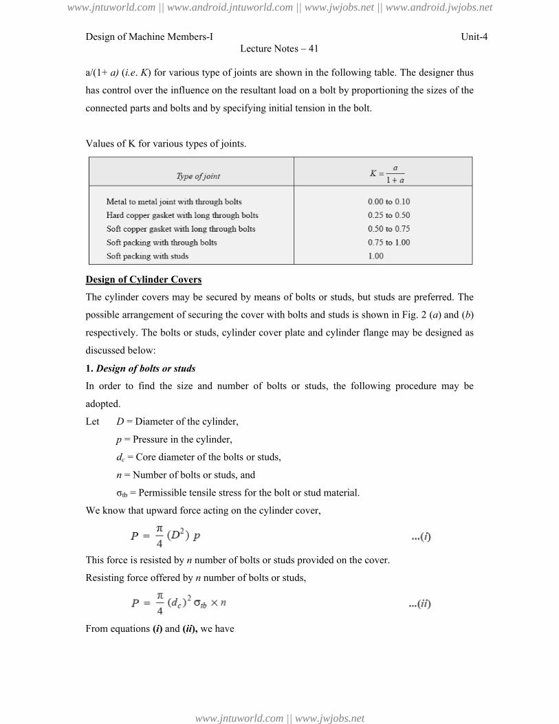
Design of Machine Members-I
a/(1+ a) (i.e. K) for various type of joints are shown in
has control over the influence on the resultant load on a bolt by proportioning the sizes
connected parts and bolts and by specifying initial tension in the bolt.
Values of K for various types of joints.
Design of Cylinder Covers
The cylinder covers may be secured by means of bolts or studs, but studs are preferred. The
possible arrangement of securing the cover with bolts and studs is shown in Fig.
respectively. The bolts or studs, cylinder cover plate and cylinder flange may be desig
discussed below:
1. Design of bolts or studs
In order to find the size and number of bolts or studs, the following procedure may be
adopted.
Let D = Diameter of the cylinder,
p = Pressure in the cylinder,
dc = Core diameter of the bolts or studs,
n = Number of bolts or studs, and
σtb = Permissible tensile stress for the bolt or stud material.
We know that upward force acting on the cylinder cover,
This force is resisted by n number of bolts or studs provided on the cover.
Resisting force offered by n number of bolts or studs,
From equations (i) and (ii), we have
Lecture Notes – 41
) for various type of joints are shown in the following table. The
s control over the influence on the resultant load on a bolt by proportioning the sizes
connected parts and bolts and by specifying initial tension in the bolt.
Values of K for various types of joints.
s may be secured by means of bolts or studs, but studs are preferred. The
possible arrangement of securing the cover with bolts and studs is shown in Fig.
respectively. The bolts or studs, cylinder cover plate and cylinder flange may be desig
In order to find the size and number of bolts or studs, the following procedure may be
= Diameter of the cylinder,
= Pressure in the cylinder,
= Core diameter of the bolts or studs,
= Number of bolts or studs, and
= Permissible tensile stress for the bolt or stud material.
We know that upward force acting on the cylinder cover,
number of bolts or studs provided on the cover.
number of bolts or studs,
we have
Unit-4
designer thus
s control over the influence on the resultant load on a bolt by proportioning the sizes of the
s may be secured by means of bolts or studs, but studs are preferred. The
possible arrangement of securing the cover with bolts and studs is shown in Fig. 2 (a) and (b)
respectively. The bolts or studs, cylinder cover plate and cylinder flange may be designed as
In order to find the size and number of bolts or studs, the following procedure may be
www.jntuworld.com || www.android.jntuworld.com || www.jwjobs.net || www.android.jwjobs.net
www.jntuworld.com || www.jwjobs.net
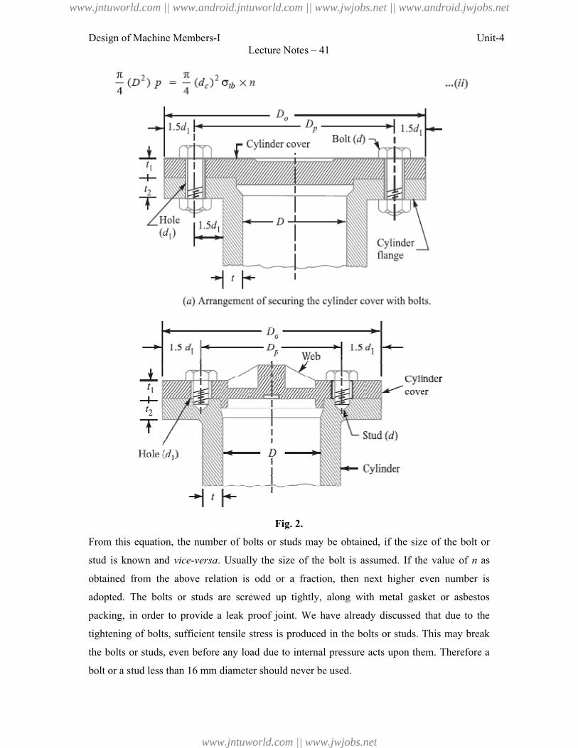
Design of Machine Members-I
From this equation, the number of bolts or studs may be obtained, if the size of the bolt or
stud is known and vice-versa. Usually the size of the bolt is assumed. If the v
obtained from the above relation is odd or a fraction, then next higher even number is
adopted. The bolts or studs are screwed up tightly, along with metal gasket or asbestos
packing, in order to provide a leak proof joint. We have already dis
tightening of bolts, sufficient tensile stress is produced in the bolts or studs. This may break
the bolts or studs, even before any load
bolt or a stud less than 16 mm diameter sh
Lecture Notes – 41
Fig. 2.
From this equation, the number of bolts or studs may be obtained, if the size of the bolt or
. Usually the size of the bolt is assumed. If the v
above relation is odd or a fraction, then next higher even number is
The bolts or studs are screwed up tightly, along with metal gasket or asbestos
to provide a leak proof joint. We have already discussed that due to the
tensile stress is produced in the bolts or studs. This may break
the bolts or studs, even before any load due to internal pressure acts upon them. Therefore a
bolt or a stud less than 16 mm diameter should never be used.
Unit-4
From this equation, the number of bolts or studs may be obtained, if the size of the bolt or
. Usually the size of the bolt is assumed. If the value of n as
above relation is odd or a fraction, then next higher even number is
The bolts or studs are screwed up tightly, along with metal gasket or asbestos
cussed that due to the
tensile stress is produced in the bolts or studs. This may break
due to internal pressure acts upon them. Therefore a
www.jntuworld.com || www.android.jntuworld.com || www.jwjobs.net || www.android.jwjobs.net
www.jntuworld.com || www.jwjobs.net
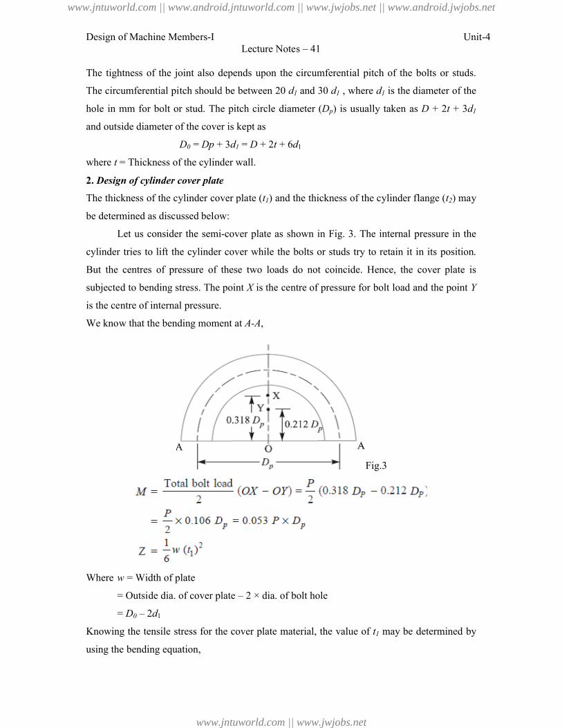
Design of Machine Members-I
The tightness of the joint also depends upon the circumferential pitch of the bolts or studs.
The circumferential pitch should be between 20
hole in mm for bolt or stud. The pitch circle
and outside diameter of the cover is kept as
D0 = Dp + 3
where t = Thickness of the cylinder wall.
2. Design of cylinder cover plate
The thickness of the cylinder cover plate (
be determined as discussed below:
Let us consider the semi-
cylinder tries to lift the cylinder cover while the bolts or studs try to retain
But the centres of pressure of these two
subjected to bending stress. The point
is the centre of internal pressure.
We know that the bending moment at
Where w = Width of plate
= Outside dia. of cover plate
= D0 – 2d1
Knowing the tensile stress for the cover plate material, the
using the bending equation,
Lecture Notes – 41
The tightness of the joint also depends upon the circumferential pitch of the bolts or studs.
circumferential pitch should be between 20 d1 and 30 d1 , where d1 is the diameter of the
mm for bolt or stud. The pitch circle diameter (Dp) is usually taken as
diameter of the cover is kept as
+ 3d1 = D + 2t + 6d1
= Thickness of the cylinder wall.
Design of cylinder cover plate
The thickness of the cylinder cover plate (t1) and the thickness of the cylinder flange (
determined as discussed below:
-cover plate as shown in Fig. 3. The internal pressure in the
lift the cylinder cover while the bolts or studs try to retain it in its
But the centres of pressure of these two loads do not coincide. Hence, the cover plate is
to bending stress. The point X is the centre of pressure for bolt load and the point
g moment at A-A,
Fig.3
= Outside dia. of cover plate – 2 × dia. of bolt hole
Knowing the tensile stress for the cover plate material, the value of t1 may be determined by
Unit-4
The tightness of the joint also depends upon the circumferential pitch of the bolts or studs.
is the diameter of the
) is usually taken as D + 2t + 3d1
thickness of the cylinder flange (t2) may
. The internal pressure in the
it in its position.
loads do not coincide. Hence, the cover plate is
for bolt load and the point Y
may be determined by
www.jntuworld.com || www.android.jntuworld.com || www.jwjobs.net || www.android.jwjobs.net
www.jntuworld.com || www.jwjobs.net
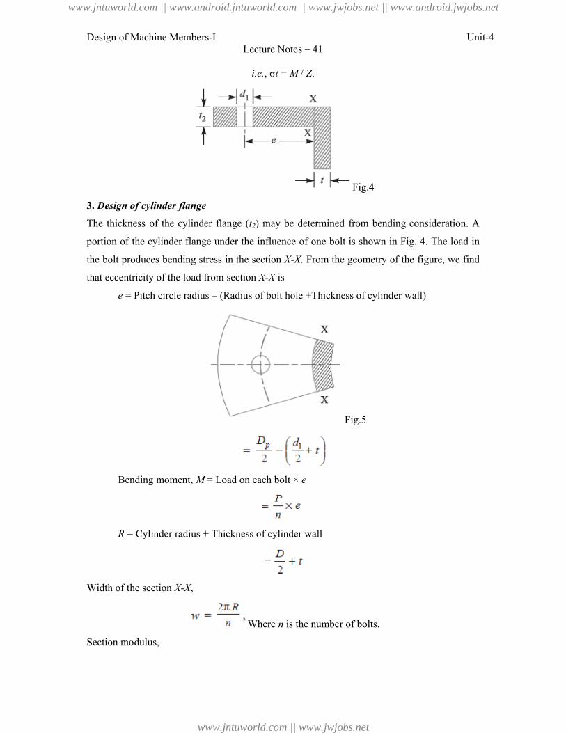
Design of Machine Members-I
3. Design of cylinder flange
The thickness of the cylinder flange (
portion of the cylinder flange under the influence of
the bolt produces bending stress
that eccentricity of the load from section
e = Pitch circle radius – (Radius of bolt hole +Thickness of cylinder wall)
Bending moment, M = Load on each bolt ×
R = Cylinder radius + Thickness of cylinder wall
Width of the section X-X,
Section modulus,
Lecture Notes – 41
i.e., σt = M / Z.
Fig.4
The thickness of the cylinder flange (t2) may be determined from bending consideration. A
under the influence of one bolt is shown in Fig. 4
the bolt produces bending stress in the section X-X. From the geometry of the figure, we find
of the load from section X-X is
(Radius of bolt hole +Thickness of cylinder wall)
Fig.5
= Load on each bolt × e
radius + Thickness of cylinder wall
Where n is the number of bolts.
Unit-4
from bending consideration. A
one bolt is shown in Fig. 4. The load in
. From the geometry of the figure, we find
(Radius of bolt hole +Thickness of cylinder wall)
www.jntuworld.com || www.android.jntuworld.com || www.jwjobs.net || www.android.jwjobs.net
www.jntuworld.com || www.jwjobs.net
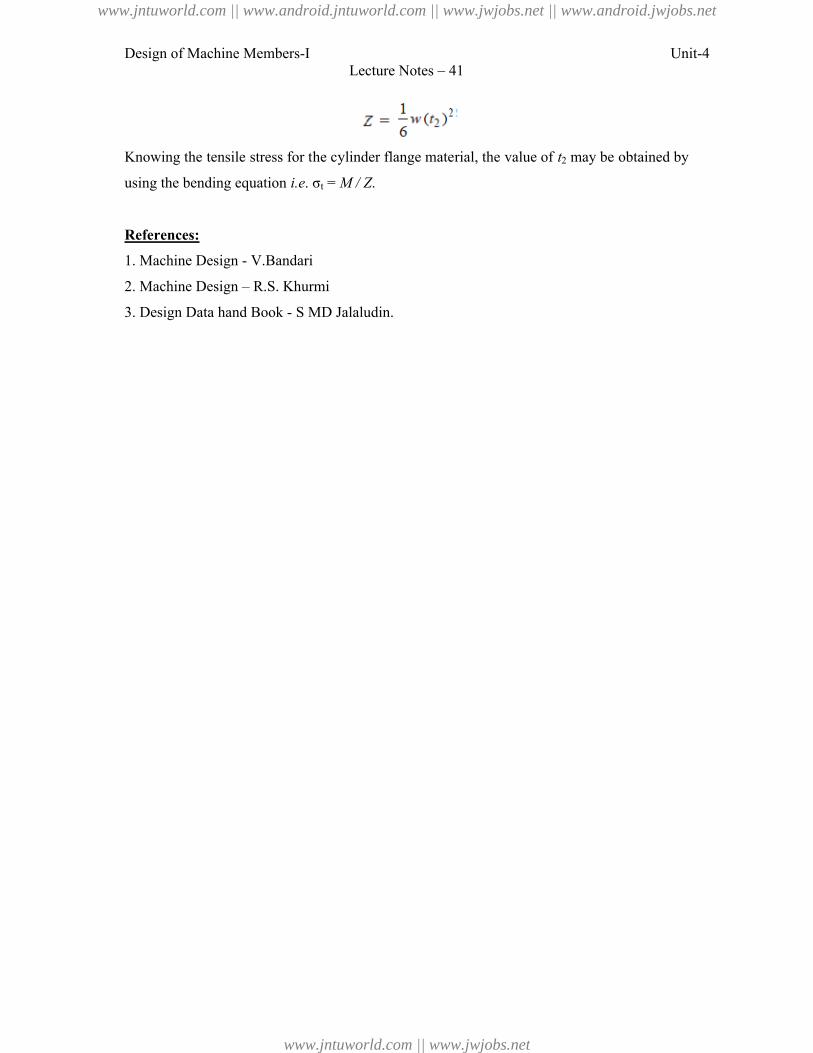
Design of Machine Members-I Unit-4Lecture Notes – 41
Knowing the tensile stress for the cylinder flange material, the value of t2 may be obtained by
using the bending equation i.e. σt = M / Z.
References:
1. Machine Design - V.Bandari
2. Machine Design – R.S. Khurmi
3. Design Data hand Book - S MD Jalaludin.
www.jntuworld.com || www.android.jntuworld.com || www.jwjobs.net || www.android.jwjobs.net
www.jntuworld.com || www.jwjobs.net
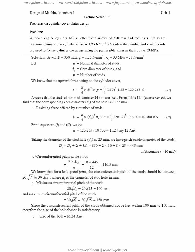
Design of Machine Members-I
Problems on cylinder cover plates design
Problem:
A steam engine cylinder has an effective diameter of 350 mm and the maximum
pressure acting on the cylinder cover is 1.25 N/mm
required to fix the cylinder cover, assuming the permissible stress in the studs as 33 MPa.
Lecture Notes – 42
Problems on cylinder cover plates design
A steam engine cylinder has an effective diameter of 350 mm and the maximum
pressure acting on the cylinder cover is 1.25 N/mm2. Calculate the number and size of studs
cover, assuming the permissible stress in the studs as 33 MPa.
Unit-4
A steam engine cylinder has an effective diameter of 350 mm and the maximum steam
. Calculate the number and size of studs
cover, assuming the permissible stress in the studs as 33 MPa.
www.jntuworld.com || www.android.jntuworld.com || www.jwjobs.net || www.android.jwjobs.net
www.jntuworld.com || www.jwjobs.net
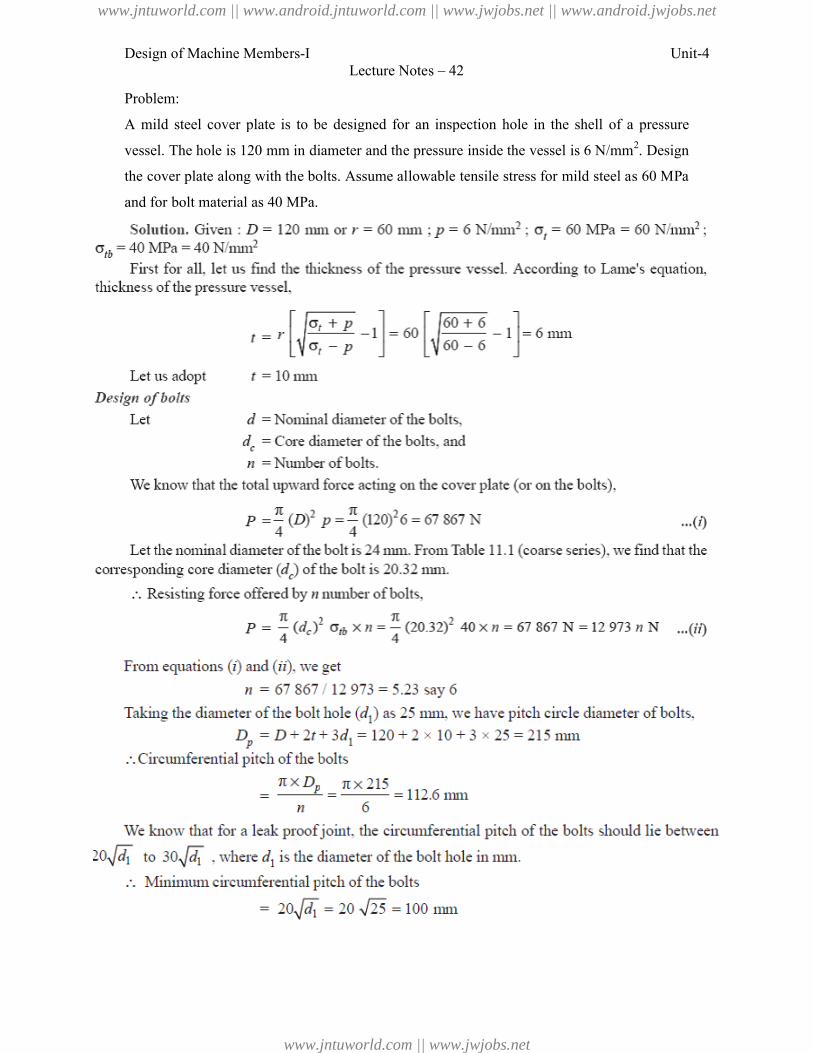
Design of Machine Members-I
Problem:
A mild steel cover plate is to be designed for an inspection hole in the shell of a
vessel. The hole is 120 mm in diameter and the pressure inside the vessel is 6 N/mm
the cover plate along with the bolts. Assume allowable tensile stress for mild steel as 60 MPa
and for bolt material as 40 MPa.
Lecture Notes – 42
A mild steel cover plate is to be designed for an inspection hole in the shell of a
vessel. The hole is 120 mm in diameter and the pressure inside the vessel is 6 N/mm
the cover plate along with the bolts. Assume allowable tensile stress for mild steel as 60 MPa
Unit-4
A mild steel cover plate is to be designed for an inspection hole in the shell of a pressure
vessel. The hole is 120 mm in diameter and the pressure inside the vessel is 6 N/mm2. Design
the cover plate along with the bolts. Assume allowable tensile stress for mild steel as 60 MPa
www.jntuworld.com || www.android.jntuworld.com || www.jwjobs.net || www.android.jwjobs.net
www.jntuworld.com || www.jwjobs.net
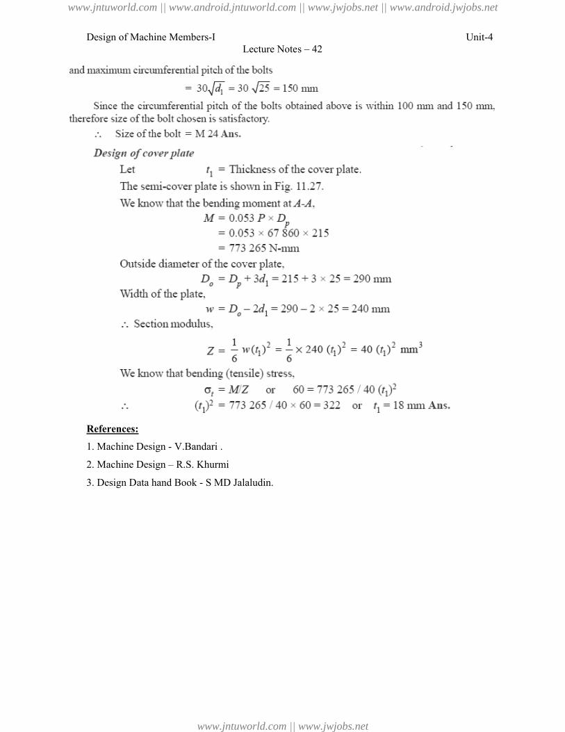
Design of Machine Members-I
References:
1. Machine Design - V.Bandari .
2. Machine Design – R.S. Khurmi
3. Design Data hand Book - S MD
Lecture Notes – 42
V.Bandari .
R.S. Khurmi
S MD Jalaludin.
Unit-4
www.jntuworld.com || www.android.jntuworld.com || www.jwjobs.net || www.android.jwjobs.net
www.jntuworld.com || www.jwjobs.net

Design of Machine Members-I Unit-4Lecture Notes – 42
www.jntuworld.com || www.android.jntuworld.com || www.jwjobs.net || www.android.jwjobs.net
www.jntuworld.com || www.jwjobs.net
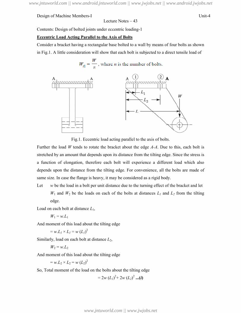
Design of Machine Members-I
Contents: Design of bolted joints under eccentric loading
Eccentric Load Acting Parallel to the Axis of Bolts
Consider a bracket having a rectangular base bolted to a wall by means of four bolts as shown
in Fig.1. A little consideration will show that
Fig.1. Eccentric load acting parallel to the axis of bolts.
Further the load W tends to rotate the bracket about the edge
stretched by an amount that depends upon its dis
a function of elongation, therefore each bolt will experience a different load which also
depends upon the distance from the tilting edge. For convenience, all the bolts are made of
same size. In case the flange is heavy, it may be considered as a rigid body.
Let w be the load in a bolt per unit distance due to the turning effect of the bracket and let
W1 and W2 be the loads on each of the bolts at distances
edge.
Load on each bolt at distance L1,
W1 = w.L1
And moment of this load about the tilting edge
= w.L1 × L1 = w (L1)2
Similarly, load on each bolt at distance
W2 = w.L2
And moment of this load about the tilting edge
= w.L2 × L2 = w (L2)2
So, Total moment of the load on the
Lecture Notes – 43
Contents: Design of bolted joints under eccentric loading-1
Eccentric Load Acting Parallel to the Axis of Bolts
Consider a bracket having a rectangular base bolted to a wall by means of four bolts as shown
. A little consideration will show that each bolt is subjected to a direct tensile load of
Eccentric load acting parallel to the axis of bolts.
tends to rotate the bracket about the edge A-A. Due to this, each bolt is
stretched by an amount that depends upon its distance from the tilting edge. Since the stress is
function of elongation, therefore each bolt will experience a different load which also
the distance from the tilting edge. For convenience, all the bolts are made of
ange is heavy, it may be considered as a rigid body.
be the load in a bolt per unit distance due to the turning effect of the bracket and let
be the loads on each of the bolts at distances L1 and L2 from the tilting
,
And moment of this load about the tilting edge
Similarly, load on each bolt at distance L2,
And moment of this load about the tilting edge
Total moment of the load on the bolts about the tilting edge
= 2w (L1)2+ 2w (L2)
2 ...(i)
Unit-4
Consider a bracket having a rectangular base bolted to a wall by means of four bolts as shown
each bolt is subjected to a direct tensile load of
. Due to this, each bolt is
tance from the tilting edge. Since the stress is
function of elongation, therefore each bolt will experience a different load which also
the distance from the tilting edge. For convenience, all the bolts are made of
be the load in a bolt per unit distance due to the turning effect of the bracket and let
from the tilting
www.jntuworld.com || www.android.jntuworld.com || www.jwjobs.net || www.android.jwjobs.net
www.jntuworld.com || www.jwjobs.net
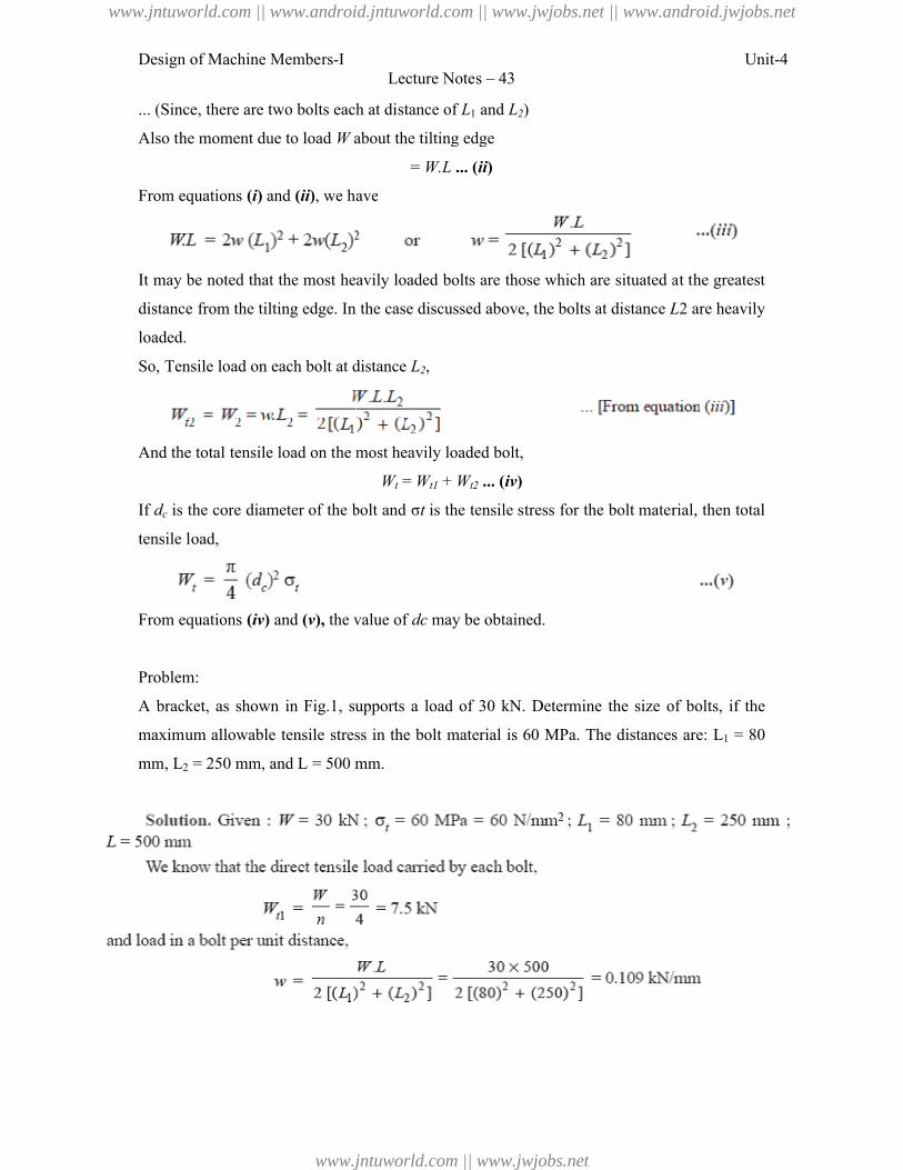
Design of Machine Members-I
... (Since, there are two bolts each at distance of
Also the moment due to load W about the tilting edge
From equations (i) and (ii), we have
It may be noted that the most heavily loaded bolts are those which are situated at the greatest
distance from the tilting edge. In the case discussed above, the bolts at distance
loaded.
So, Tensile load on each bolt at distance
And the total tensile load on the most heavily loaded bolt,
If dc is the core diameter of the bolt and σ
tensile load,
From equations (iv) and (v), the value of
Problem:
A bracket, as shown in Fig.1, supports a load of 30 kN. Determine the size
maximum allowable tensile stress in the bolt material is 60 MPa. The distances are:
mm, L2 = 250 mm, and L = 500 mm.
Lecture Notes – 43
there are two bolts each at distance of L1 and L2)
about the tilting edge
= W.L ... (ii)
, we have
most heavily loaded bolts are those which are situated at the greatest
distance from the tilting edge. In the case discussed above, the bolts at distance L
Tensile load on each bolt at distance L2,
he most heavily loaded bolt,
Wt = Wt1 + Wt2 ... (iv)
is the core diameter of the bolt and σt is the tensile stress for the bolt material, then total
the value of dc may be obtained.
, supports a load of 30 kN. Determine the size of bolts, if the
maximum allowable tensile stress in the bolt material is 60 MPa. The distances are:
500 mm.
Unit-4
most heavily loaded bolts are those which are situated at the greatest
L2 are heavily
is the tensile stress for the bolt material, then total
of bolts, if the
maximum allowable tensile stress in the bolt material is 60 MPa. The distances are: L1 = 80
www.jntuworld.com || www.android.jntuworld.com || www.jwjobs.net || www.android.jwjobs.net
www.jntuworld.com || www.jwjobs.net
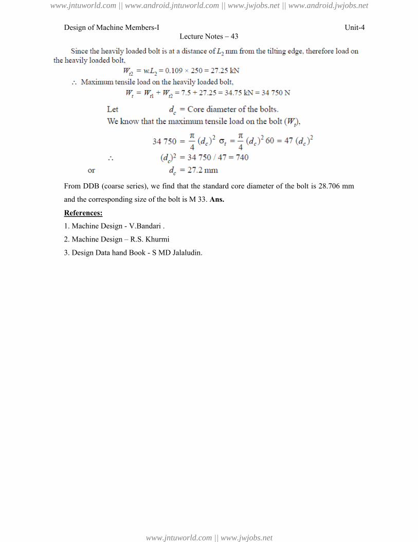
Design of Machine Members-I Unit-4Lecture Notes – 43
From DDB (coarse series), we find that the standard core diameter of the bolt is 28.706 mm
and the corresponding size of the bolt is M 33. Ans.
References:
1. Machine Design - V.Bandari .
2. Machine Design – R.S. Khurmi
3. Design Data hand Book - S MD Jalaludin.
www.jntuworld.com || www.android.jntuworld.com || www.jwjobs.net || www.android.jwjobs.net
www.jntuworld.com || www.jwjobs.net
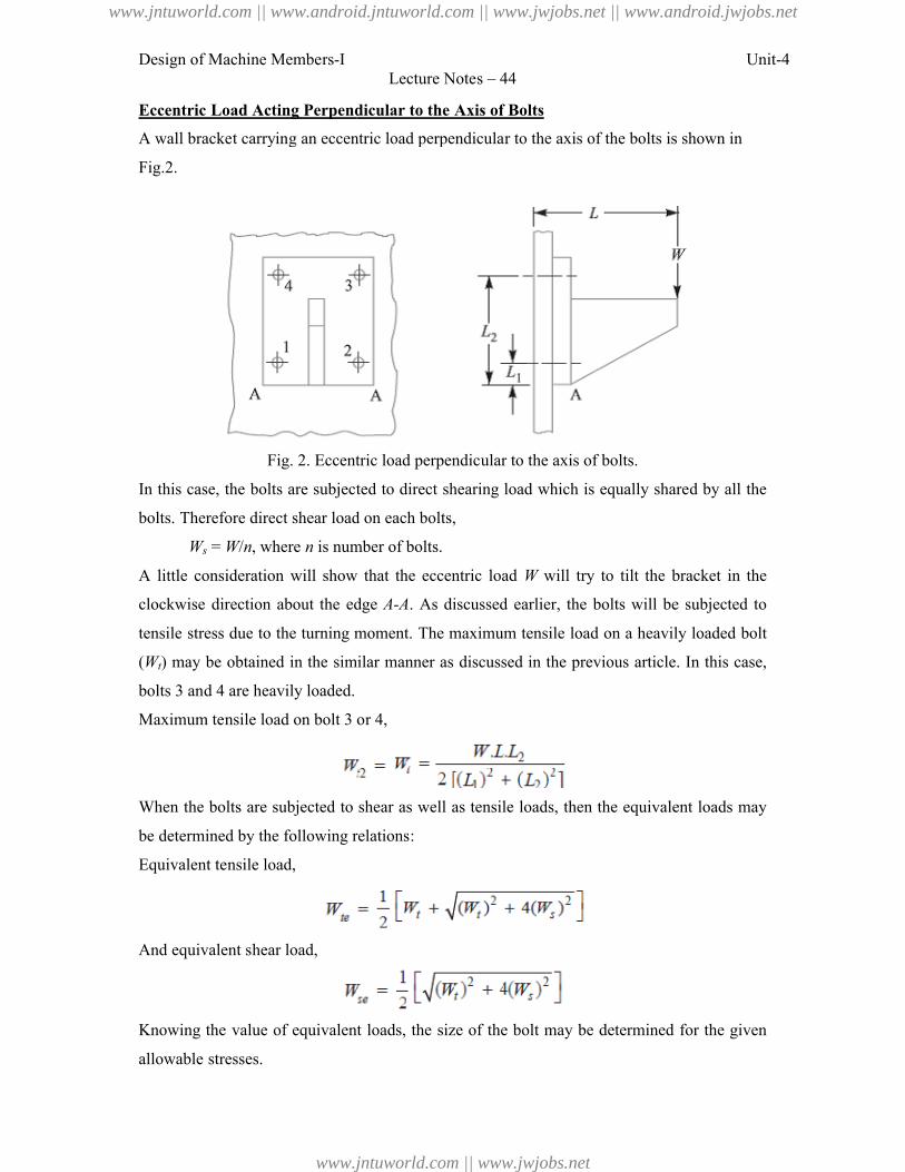
Design of Machine Members-I
Eccentric Load Acting Perpendicular to the Axis of Bolts
A wall bracket carrying an eccentric load perpendicular to the axis of the bolts is shown in
Fig.2.
Fig. 2. Eccentric load perpendicular to the axis of bolts.
In this case, the bolts are subjected
bolts. Therefore direct shear load on each bolts,
Ws = W/n, where n is number of bolts.
A little consideration will show that the eccentric load
clockwise direction about the edge
tensile stress due to the turning moment. The maximum tensile load on a heavily loaded bolt
(Wt) may be obtained in the similar manner as discussed in the previous article. In
bolts 3 and 4 are heavily loaded.
Maximum tensile load on bolt 3 or 4,
When the bolts are subjected to shear as well as tensile loads, then the equivalent loads may
be determined by the following relations:
Equivalent tensile load,
And equivalent shear load,
Knowing the value of equivalent loads, the size of the bolt may be determined for the given
allowable stresses.
Lecture Notes – 44
Eccentric Load Acting Perpendicular to the Axis of Bolts
A wall bracket carrying an eccentric load perpendicular to the axis of the bolts is shown in
Eccentric load perpendicular to the axis of bolts.
In this case, the bolts are subjected to direct shearing load which is equally shared by all the
bolts. Therefore direct shear load on each bolts,
is number of bolts.
A little consideration will show that the eccentric load W will try to tilt the bracket in the
ection about the edge A-A. As discussed earlier, the bolts will be subjected to
due to the turning moment. The maximum tensile load on a heavily loaded bolt
in the similar manner as discussed in the previous article. In
Maximum tensile load on bolt 3 or 4,
When the bolts are subjected to shear as well as tensile loads, then the equivalent loads may
determined by the following relations:
Knowing the value of equivalent loads, the size of the bolt may be determined for the given
Unit-4
A wall bracket carrying an eccentric load perpendicular to the axis of the bolts is shown in
to direct shearing load which is equally shared by all the
will try to tilt the bracket in the
. As discussed earlier, the bolts will be subjected to
due to the turning moment. The maximum tensile load on a heavily loaded bolt
in the similar manner as discussed in the previous article. In this case,
When the bolts are subjected to shear as well as tensile loads, then the equivalent loads may
Knowing the value of equivalent loads, the size of the bolt may be determined for the given
www.jntuworld.com || www.android.jntuworld.com || www.jwjobs.net || www.android.jwjobs.net
www.jntuworld.com || www.jwjobs.net
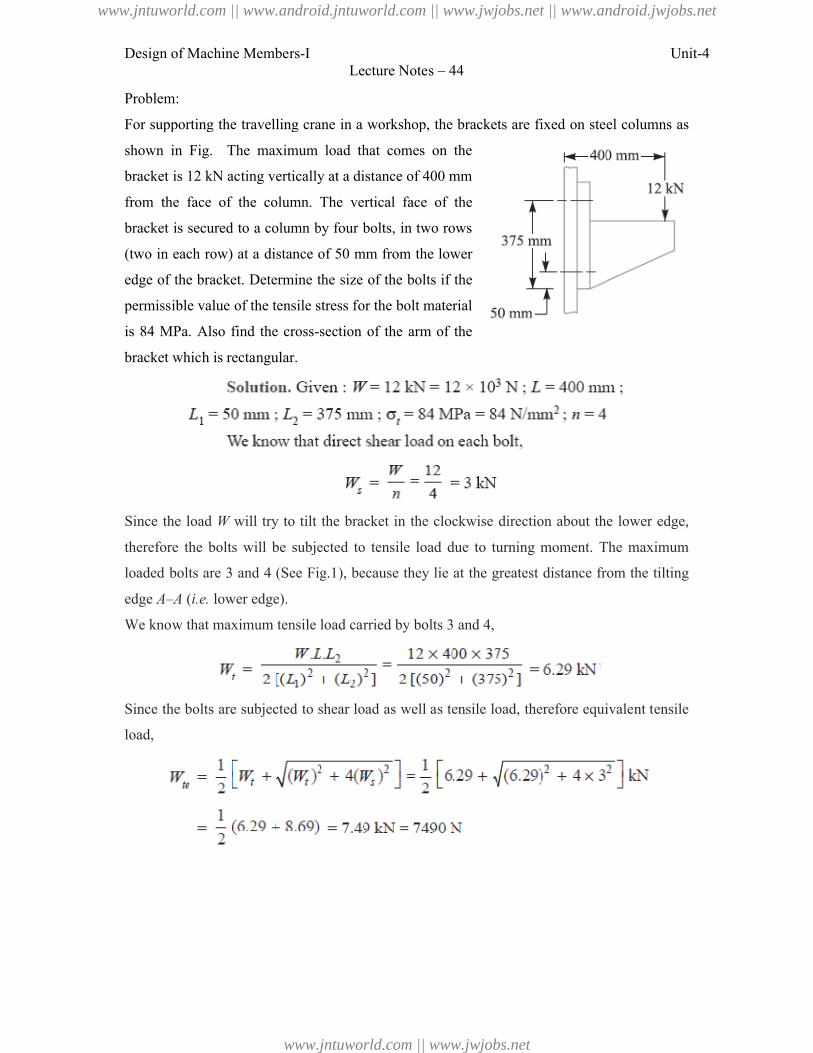
Design of Machine Members-I
Problem:
For supporting the travelling crane in a workshop, the brackets are fixed on
shown in Fig. The maximum load that comes on the
bracket is 12 kN acting vertically at a distance of 400 mm
from the face of the column. The vertical face of the
bracket is secured to a column by four bolts, in two rows
(two in each row) at a distance of 50 mm from the
edge of the bracket. Determine the
permissible value of the tensile stress for the
is 84 MPa. Also find the cross-section of the arm of the
bracket which is rectangular.
Since the load W will try to tilt the
therefore the bolts will be subjected to tensile load due to turning moment. The maximum
loaded bolts are 3 and 4 (See Fig
edge A–A (i.e. lower edge).
We know that maximum tensile load carried by bolts 3 and 4,
Since the bolts are subjected to shear load as well as tensile load, therefore equivalent tensile
load,
Lecture Notes – 44
For supporting the travelling crane in a workshop, the brackets are fixed on steel columns as
The maximum load that comes on the
vertically at a distance of 400 mm
from the face of the column. The vertical face of the
secured to a column by four bolts, in two rows
distance of 50 mm from the lower
edge of the bracket. Determine the size of the bolts if the
permissible value of the tensile stress for the bolt material
section of the arm of the
will try to tilt the bracket in the clockwise direction about the lower edge,
therefore the bolts will be subjected to tensile load due to turning moment. The maximum
bolts are 3 and 4 (See Fig.1), because they lie at the greatest distance from the tilting
We know that maximum tensile load carried by bolts 3 and 4,
Since the bolts are subjected to shear load as well as tensile load, therefore equivalent tensile
Unit-4
steel columns as
bracket in the clockwise direction about the lower edge,
therefore the bolts will be subjected to tensile load due to turning moment. The maximum
), because they lie at the greatest distance from the tilting
Since the bolts are subjected to shear load as well as tensile load, therefore equivalent tensile
www.jntuworld.com || www.android.jntuworld.com || www.jwjobs.net || www.android.jwjobs.net
www.jntuworld.com || www.jwjobs.net
Design of Machine Members-I
References:
1. Machine Design - V.Bandari .
2. Machine Design – R.S. Khurmi
3. Design Data hand Book - S MD Jalaludin
Lecture Notes – 44
V.Bandari .
Khurmi
S MD Jalaludin.
Unit-4
www.jntuworld.com || www.android.jntuworld.com || www.jwjobs.net || www.android.jwjobs.net
www.jntuworld.com || www.jwjobs.net

Design of Machine Members-I Unit-4Lecture Notes – 44
www.jntuworld.com || www.android.jntuworld.com || www.jwjobs.net || www.android.jwjobs.net
www.jntuworld.com || www.jwjobs.net
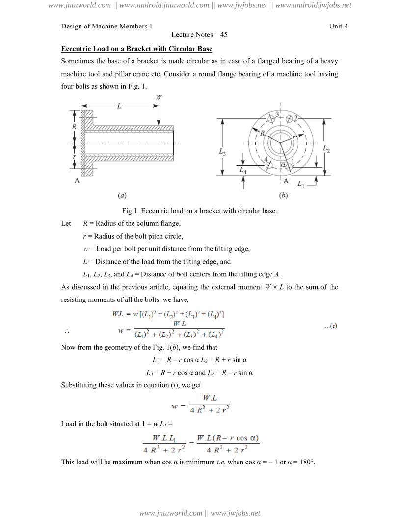
Design of Machine Members-I
Eccentric Load on a Bracket with Circular Base
Sometimes the base of a bracket is made circular as in case of a flanged bearing of a heavy
machine tool and pillar crane etc. Consider a round flange bearing of a machine tool having
four bolts as shown in Fig. 1.
Fig.1. Eccentric load on a bracket with circular base.
Let R = Radius of the column flange,
r = Radius of the bolt pitch circle,
w = Load per bolt per unit distance from the tilting edge,
L = Distance of the load from the tilting ed
L1, L2, L3, and L4 = Distance of bolt
As discussed in the previous article, equating the external moment
resisting moments of all the bolts, we have,
Now from the geometry of the Fig.
L1
L3 =
Substituting these values in equation (
Load in the bolt situated at 1 = w.L
This load will be maximum when cos α is minimum
Lecture Notes – 45
Eccentric Load on a Bracket with Circular Base
Sometimes the base of a bracket is made circular as in case of a flanged bearing of a heavy
machine tool and pillar crane etc. Consider a round flange bearing of a machine tool having
Fig.1. Eccentric load on a bracket with circular base.
= Radius of the column flange,
= Radius of the bolt pitch circle,
= Load per bolt per unit distance from the tilting edge,
= Distance of the load from the tilting edge, and
= Distance of bolt centers from the tilting edge A.
As discussed in the previous article, equating the external moment W × L to the sum of the
resisting moments of all the bolts, we have,
Now from the geometry of the Fig. 1(b), we find that
1 = R – r cos α L2 = R + r sin α
= R + r cos α and L4 = R – r sin α
Substituting these values in equation (i), we get
w.L1 =
This load will be maximum when cos α is minimum i.e. when cos α = – 1 or α =
Unit-4
Sometimes the base of a bracket is made circular as in case of a flanged bearing of a heavy
machine tool and pillar crane etc. Consider a round flange bearing of a machine tool having
to the sum of the
180°.
www.jntuworld.com || www.android.jntuworld.com || www.jwjobs.net || www.android.jwjobs.net
www.jntuworld.com || www.jwjobs.net
Design of Machine Members-I
Maximum load in a bolt
In general, if there are n number of bolts, then
And maximum load in a bolt,
The above relation is used when the direction of the load
as in the case of pillar crane. But if the direction of load is fixed, then the maximum load on
the bolts may be reduced by locating the bolts in such a way that two of them are equally
stressed as shown in Fig.2. In such a case, maximum load is given by
Knowing the value of maximum l
we can determine the size of the bolt.
Note: Generally, two dowel pins as
shown in Fig. 2, are used to take up the
shear load. Thus the bolts are relieved
of shear stress and the bolts are
designed for tensile load only.
Problem:
A flanged bearing, as shown in Fig.1
equally on 500 mm bolt circle. The diameter of bearing flange is 650 mm and a
kN acts at a distance of 250 mm from the frame. Determine the size of the bolts
tensile stress as 60 MPa for the material of the bolts.
Lecture Notes – 45
number of bolts, then load in a bolt
The above relation is used when the direction of the load W changes with relation to the bolts
ut if the direction of load is fixed, then the maximum load on
may be reduced by locating the bolts in such a way that two of them are equally
. In such a case, maximum load is given by
Knowing the value of maximum load,
we can determine the size of the bolt.
dowel pins as
, are used to take up the
relieved
of shear stress and the bolts are
Fig.2.
anged bearing, as shown in Fig.1, is fastened to a frame by means of four bolts spaced
equally on 500 mm bolt circle. The diameter of bearing flange is 650 mm and a
kN acts at a distance of 250 mm from the frame. Determine the size of the bolts
tensile stress as 60 MPa for the material of the bolts.
Unit-4
changes with relation to the bolts
ut if the direction of load is fixed, then the maximum load on
may be reduced by locating the bolts in such a way that two of them are equally
four bolts spaced
equally on 500 mm bolt circle. The diameter of bearing flange is 650 mm and a load of 400
kN acts at a distance of 250 mm from the frame. Determine the size of the bolts, taking safe
www.jntuworld.com || www.android.jntuworld.com || www.jwjobs.net || www.android.jwjobs.net
www.jntuworld.com || www.jwjobs.net
Design of Machine Members-I Unit-4Lecture Notes – 45
From DDB, we find that the standard core diameter of the bolt is 45.795 mm and
corresponding size of the bolt is M 52. Ans.
References:
1. Machine Design - V.Bandari .
2. Machine Design – R.S. Khurmi
3. Design Data hand Book - S MD Jalaludin.
www.jntuworld.com || www.android.jntuworld.com || www.jwjobs.net || www.android.jwjobs.net
www.jntuworld.com || www.jwjobs.net
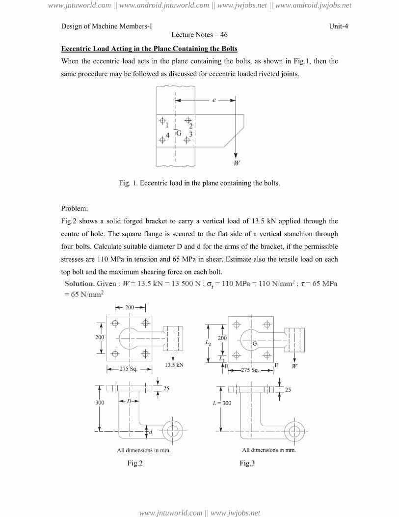
Design of Machine Members-I
Eccentric Load Acting in the Plane Containing the Bolts
When the eccentric load acts in the plane containing the bolts,
same procedure may be followed
Fig. 1. Eccentric load
Problem:
Fig.2 shows a solid forged bracket to carry a vertical load of 13.5 kN
centre of hole. The square flange is secured to the flat side of a vertical stanchion
four bolts. Calculate suitable diameter D and d for the arms of the bracket, if the permissible
stresses are 110 MPa in tenstion and 65 MPa in shear.
top bolt and the maximum shearing force on each bolt.
Fig.2
Lecture Notes – 46
Eccentric Load Acting in the Plane Containing the Bolts
When the eccentric load acts in the plane containing the bolts, as shown in Fig.1
same procedure may be followed as discussed for eccentric loaded riveted joints.
Fig. 1. Eccentric load in the plane containing the bolts.
shows a solid forged bracket to carry a vertical load of 13.5 kN applied through the
centre of hole. The square flange is secured to the flat side of a vertical stanchion
table diameter D and d for the arms of the bracket, if the permissible
stresses are 110 MPa in tenstion and 65 MPa in shear. Estimate also the tensile load on each
top bolt and the maximum shearing force on each bolt.
Fig.3
Unit-4
as shown in Fig.1, then the
as discussed for eccentric loaded riveted joints.
applied through the
centre of hole. The square flange is secured to the flat side of a vertical stanchion through
table diameter D and d for the arms of the bracket, if the permissible
Estimate also the tensile load on each
www.jntuworld.com || www.android.jntuworld.com || www.jwjobs.net || www.android.jwjobs.net
www.jntuworld.com || www.jwjobs.net
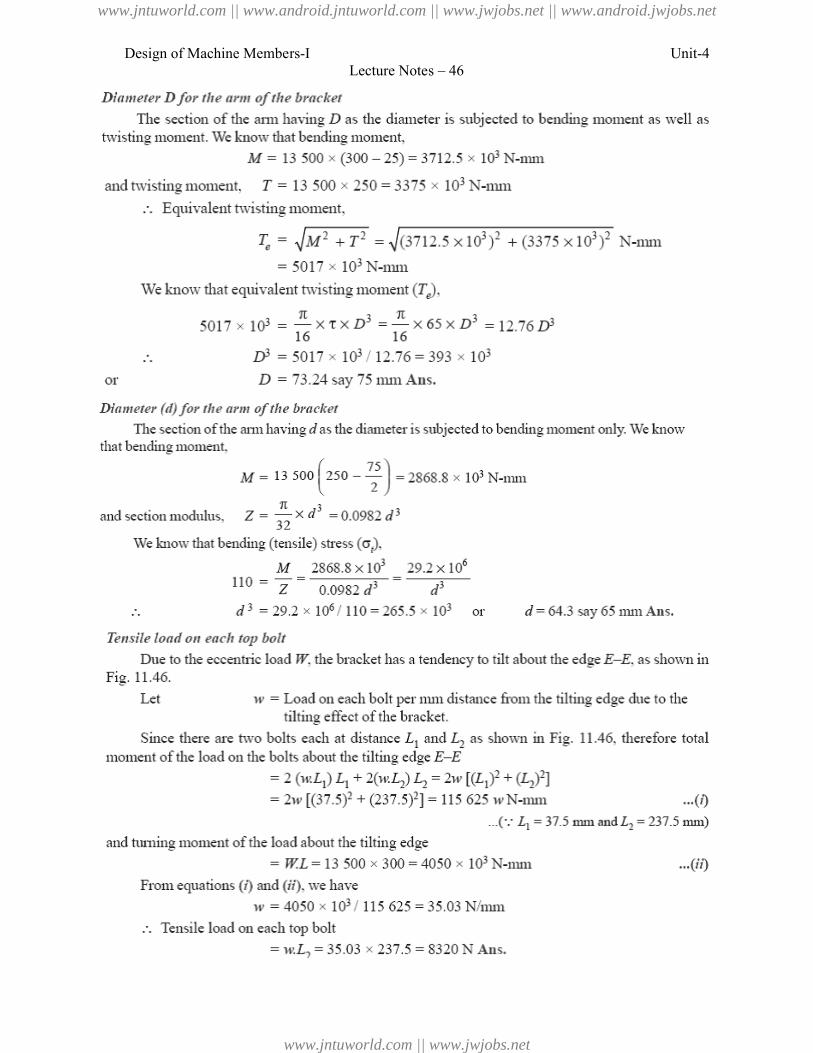
Design of Machine Members-ILecture Notes – 46
Unit-4
www.jntuworld.com || www.android.jntuworld.com || www.jwjobs.net || www.android.jwjobs.net
www.jntuworld.com || www.jwjobs.net
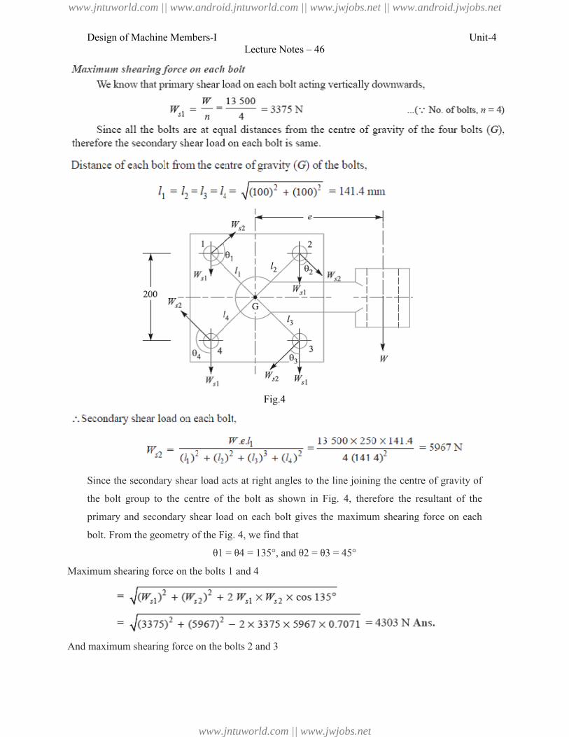
Design of Machine Members-I
Since the secondary shear load acts at right angles to the line joining the centre of gravity of
the bolt group to the centre of the bolt as shown in Fig
primary and secondary shear load on each bolt gives the
bolt. From the geometry of the Fig. 4
θ1 = θ4 = 135°, and θ2 = θ3 = 45°
Maximum shearing force on the bolts 1 and 4
And maximum shearing force on the bolts 2 and 3
Lecture Notes – 46
Fig.4
Since the secondary shear load acts at right angles to the line joining the centre of gravity of
bolt group to the centre of the bolt as shown in Fig. 4, therefore the resultant of the
secondary shear load on each bolt gives the maximum shearing force on each
From the geometry of the Fig. 4, we find that
θ1 = θ4 = 135°, and θ2 = θ3 = 45°
Maximum shearing force on the bolts 1 and 4
And maximum shearing force on the bolts 2 and 3
Unit-4
Since the secondary shear load acts at right angles to the line joining the centre of gravity of
, therefore the resultant of the
maximum shearing force on each
www.jntuworld.com || www.android.jntuworld.com || www.jwjobs.net || www.android.jwjobs.net
www.jntuworld.com || www.jwjobs.net
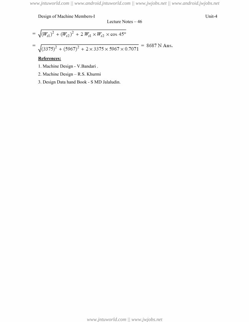
Design of Machine Members-I
References:
1. Machine Design - V.Bandari .
2. Machine Design – R.S. Khurmi
3. Design Data hand Book - S MD Jalaludin.
Lecture Notes – 46
R.S. Khurmi
S MD Jalaludin.
Unit-4
www.jntuworld.com || www.android.jntuworld.com || www.jwjobs.net || www.android.jwjobs.net
www.jntuworld.com || www.jwjobs.net
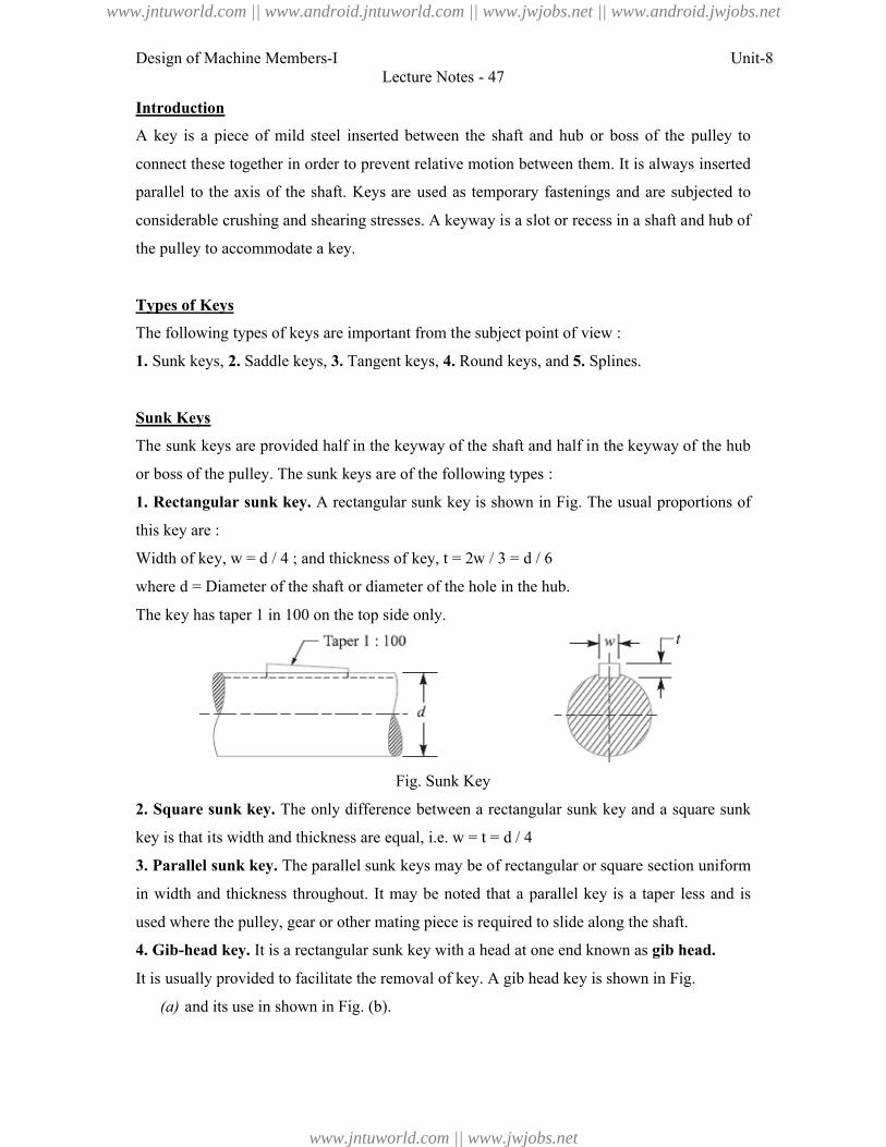
Design of Machine Members-I
Introduction
A key is a piece of mild steel inserted
connect these together in order to prevent
parallel to the axis of the shaft. Keys
considerable crushing and shearing stre
the pulley to accommodate a key.
Types of Keys
The following types of keys are important from the
1. Sunk keys, 2. Saddle keys, 3. Tangent keys,
Sunk Keys
The sunk keys are provided half in
or boss of the pulley. The sunk keys are of the following types :
1. Rectangular sunk key. A rectangula
this key are :
Width of key, w = d / 4 ; and thickness of key,
where d = Diameter of the shaft or diameter of the hole in the hub.
The key has taper 1 in 100 on the top side only.
2. Square sunk key. The only difference
key is that its width and thickness are
3. Parallel sunk key. The parallel s
in width and thickness throughout.
used where the pulley, gear or other
4. Gib-head key. It is a rectangular
It is usually provided to facilitate the removal
(a) and its use in shown in Fig.
Lecture Notes - 47
mild steel inserted between the shaft and hub or boss of the
in order to prevent relative motion between them. It is always
the shaft. Keys are used as temporary fastenings and are subjected
crushing and shearing stresses. A keyway is a slot or recess in a shaft and
key.
ypes of keys are important from the subject point of view :
Tangent keys, 4. Round keys, and 5. Splines.
re provided half in the keyway of the shaft and half in the keyway
boss of the pulley. The sunk keys are of the following types :
A rectangular sunk key is shown in Fig. The usual proportions
/ 4 ; and thickness of key, t = 2w / 3 = d / 6
of the shaft or diameter of the hole in the hub.
in 100 on the top side only.
Fig. Sunk Key
The only difference between a rectangular sunk key and a square
s width and thickness are equal, i.e. w = t = d / 4
The parallel sunk keys may be of rectangular or square section
thickness throughout. It may be noted that a parallel key is a taper
re the pulley, gear or other mating piece is required to slide along the shaft.
It is a rectangular sunk key with a head at one end known as gib head
ly provided to facilitate the removal of key. A gib head key is shown in Fig.
hown in Fig. (b).
Unit-8
or boss of the pulley to
always inserted
fastenings and are subjected to
recess in a shaft and hub of
n the keyway of the hub
The usual proportions of
sunk key and a square sunk
or square section uniform
key is a taper less and is
quired to slide along the shaft.
gib head.
s shown in Fig.
www.jntuworld.com || www.android.jntuworld.com || www.jwjobs.net || www.android.jwjobs.net
www.jntuworld.com || www.jwjobs.net
Design of Machine Members-I
Fig. Gib hea
The usual proportions of the gib head key are:
Width, w = d / 4 ; and thickness at large e
5. Feather key. A key attached to
movement is known as feather key
turning moment and also permits axial
key being a sliding fit in the key way of the moving piece.
6. Woodruff key. The woodruff
cylindrical disc having segmental cross
key is capable of tilting in a recess
curvature as the disc from which
and automobile construction.
Lecture Notes - 47
Fig. Gib head key and its use.
proportions of the gib head key are:
and thickness at large end, t = 2w / 3 = d / 6
key attached to one member of a pair and which permits relative
feather key. It is a special type of parallel key which transmits
also permits axial movement. It is fastened either to the shaft or
sliding fit in the key way of the moving piece.
Fig. Feather Keys
The woodruff key is an easily adjustable key. It is a piece
having segmental cross-section in front view as shown in Fig.
tilting in a recess milled out in the shaft by a cutter having
from which the key is made. This key is largely used in mac
Unit-8
which permits relative axial
key which transmits a
either to the shaft or hub, the
key. It is a piece from a
shown in Fig. A woodruff
cutter having the same
largely used in machine tool
www.jntuworld.com || www.android.jntuworld.com || www.jwjobs.net || www.android.jwjobs.net
www.jntuworld.com || www.jwjobs.net
Design of Machine Members-I
The main advantages of a woodruff
1. It accommodates itself to any taper
2. It is useful on tapering shaft ends. Its
over in its keyway.
The disadvantages are:
1. The depth of the keyway weakens the shaft.
2. It can not be used as a feather.
Saddle keys
The saddle keys are of the following two types:
1. Flat saddle key, and 2. Hollow s
A flat saddle key is a taper key which
shown in Fig. It is likely to slip
comparatively light loads.
Fig. Flat sadd
A hollow saddle key is a taper key
key is shaped to fit the curved surface
friction, therefore these are suitable f
in fixing and setting eccentrics, cams etc.
Lecture Notes - 47
Fig. Woodruff Key
of a woodruff key are as follows:
It accommodates itself to any taper in the hub or boss of the mating piece.
on tapering shaft ends. Its extra depth in the shaft prevents any tendenc
The depth of the keyway weakens the shaft.
s a feather.
are of the following two types:
Hollow saddle key.
a taper key which fits in a keyway in the hub and is flat on the
likely to slip round the shaft under load. Therefore it is
Fig. Flat saddle key and Tangent keys
is a taper key which fits in a keyway in the hub and the bottom
the curved surface of the shaft. Since hollow saddle keys hold
these are suitable for light loads. It is usually used as a temporary fas
eccentrics, cams etc.
Unit-8
vents any tendency to turn
and is flat on the shaft as
Therefore it is used for
hub and the bottom of the
saddle keys hold on by
d as a temporary fastening
www.jntuworld.com || www.android.jntuworld.com || www.jwjobs.net || www.android.jwjobs.net
www.jntuworld.com || www.jwjobs.net
Design of Machine Members-I
Tangent Keys
The tangent keys are fitted in pair
torsion in one direction only. These are used in large hea
Round Keys
The round keys, as shown in Fig. (
the shaft and partly in the hub. They
and reamed after the mating parts have been
be most appropriate for low power drives.
Splines
Sometimes, keys are made integral
the keyways broached in the hub.
splined shafts as shown in Fig. These
six, ten or sixteen splines. The splined
stronger than shafts having a single keyway.
Stresses in Keys:
Forces acting on a Sunk Key
When a key is used in transmitting
types of forces act on the key:
1. Forces (F1) due to fit of the key
tapered key driven in place. These
difficult to determine in magnitude.
2. Forces (F) due to the torque transmitted
compressive (or crushing) stresses in the key.
The forces acting on a key for a clockwis
shown in Fig.
Lecture Notes - 47
fitted in pair at right angles as shown in Fig. Each key is to
one direction only. These are used in large heavy duty shafts.
shown in Fig. (a) are circular in section and fit into holes drilled
in the hub. They have the advantage that their keyways may
e mating parts have been assembled. Round keys are usually considered to
or low power drives.
made integral with the shaft which fits
broached in the hub. Such shafts are known as
shown in Fig. These shafts usually have
splines. The splined shafts are relatively
single keyway.
in transmitting torque from a shaft to a rotor or hub, the foll
fit of the key in its keyway, as in a tight fitting straight key
place. These forces produce compressive stresses in the key
agnitude.
the torque transmitted by the shaft. These forces produce shearing
sive (or crushing) stresses in the key.
a key for a clockwise torque being transmitted from a shaft to
Unit-8
Each key is to withstand
into holes drilled partly in
keyways may be drilled
Round keys are usually considered to
in
four,
hub, the following two
fitting straight key or in a
stresses in the key which are
forces produce shearing and
from a shaft to a hub are
www.jntuworld.com || www.android.jntuworld.com || www.jwjobs.net || www.android.jwjobs.net
www.jntuworld.com || www.jwjobs.net
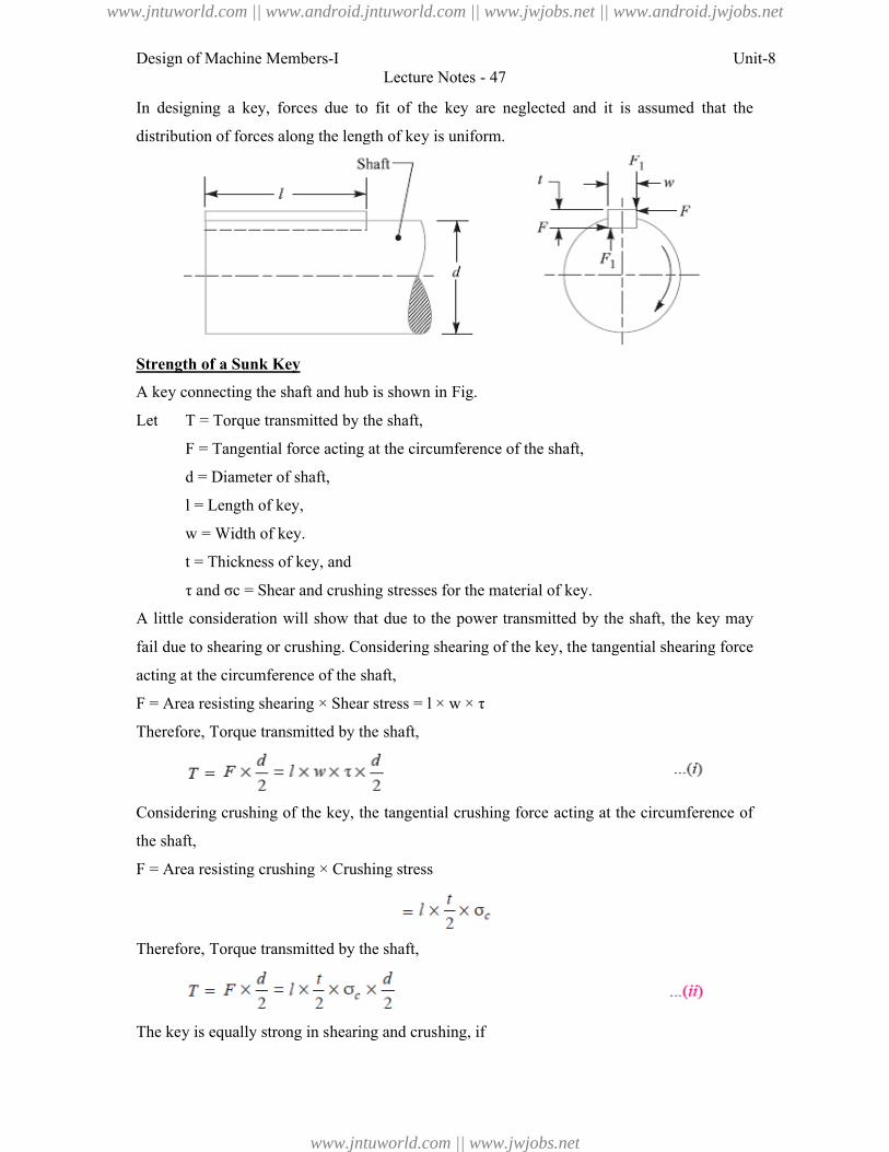
Design of Machine Members-I
In designing a key, forces due to
distribution of forces along the length
Strength of a Sunk Key
A key connecting the shaft and hub
Let T = Torque transmitted by the shaft,
F = Tangential force acting at the ci
d = Diameter of shaft,
l = Length of key,
w = Width of key.
t = Thickness of key, and
τ and σc = Shear and crushing stresses f
A little consideration will show that
fail due to shearing or crushing. Considering shearing of the
acting at the circumference of the
F = Area resisting shearing × Shear stress =
Therefore, Torque transmitted by the shaft,
Considering crushing of the key, the
the shaft,
F = Area resisting crushing × Crushing stress
Therefore, Torque transmitted by the shaft,
The key is equally strong in shearing and crushing, if
Lecture Notes - 47
forces due to fit of the key are neglected and it is assume
of forces along the length of key is uniform.
y connecting the shaft and hub is shown in Fig.
by the shaft,
= Tangential force acting at the circumference of the shaft,
= Thickness of key, and
= Shear and crushing stresses for the material of key.
how that due to the power transmitted by the shaft, the
Considering shearing of the key, the tangential shearing force
ircumference of the shaft,
earing × Shear stress = l × w × τ
Torque transmitted by the shaft,
of the key, the tangential crushing force acting at the circumference
rushing × Crushing stress
transmitted by the shaft,
is equally strong in shearing and crushing, if
Unit-8
and it is assumed that the
by the shaft, the key may
tangential shearing force
at the circumference of
www.jntuworld.com || www.android.jntuworld.com || www.jwjobs.net || www.android.jwjobs.net
www.jntuworld.com || www.jwjobs.net
Design of Machine Members-I Unit-8
Lecture Notes - 47
Or
The permissible crushing stress for the usual key material is at least twice the permissible
shearing stress. Therefore from the above equation, we have w = t. In other words, a square
key is equally strong in shearing and crushing.
In order to find the length of the key to transmit full power of the shaft, the shearing
strength of the key is equal to the torsional shear strength of the shaft. We know that the
shearing strength of key,
And torsional shear strength of the shaft,
From the above
When the key material is same as that of the shaft, then τ = τ1. So, l = 1.571 d.
References:
1. Machine Design - V.Bandari .
2. Machine Design – R.S. Khurmi
3. Design Data hand Book - S MD Jalaludin.
www.jntuworld.com || www.android.jntuworld.com || www.jwjobs.net || www.android.jwjobs.net
www.jntuworld.com || www.jwjobs.net
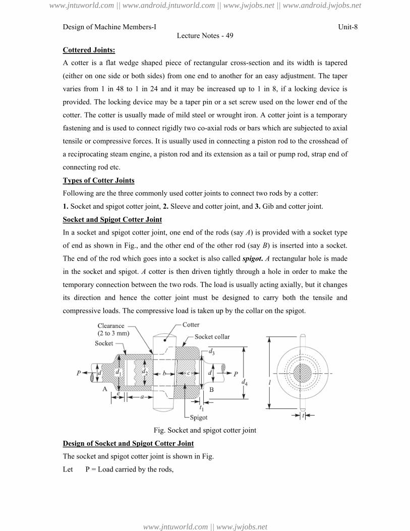
Design of Machine Members-I
Cottered Joints:
A cotter is a flat wedge shaped piece
(either on one side or both sides) from
varies from 1 in 48 to 1 in 24 and
provided. The locking device may be
cotter. The cotter is usually made of
fastening and is used to connect rigidly two
tensile or compressive forces. It is u
a reciprocating steam engine, a pisto
connecting rod etc.
Types of Cotter Joints
Following are the three commonly used cotter j
1. Socket and spigot cotter joint,
Socket and Spigot Cotter Joint
In a socket and spigot cotter joint, one
of end as shown in Fig., and the other
The end of the rod which goes into
in the socket and spigot. A cotter is
temporary connection between the tw
its direction and hence the cot
compressive loads. The compressive loa
Fig. Sock
Design of Socket and Spigot Cotter Joint
The socket and spigot cotter joint is s
Let P = Load carried by the rods,
Lecture Notes - 49
wedge shaped piece of rectangular cross-section and its width
both sides) from one end to another for an easy adjustment.
to 1 in 24 and it may be increased up to 1 in 8, if a locking
device may be a taper pin or a set screw used on the lower
usually made of mild steel or wrought iron. A cotter joint is a
to connect rigidly two co-axial rods or bars which are subjecte
It is usually used in connecting a piston rod to the crosshead
am engine, a piston rod and its extension as a tail or pump rod,
hree commonly used cotter joints to connect two rods by a cotter:
Socket and spigot cotter joint, 2. Sleeve and cotter joint, and 3. Gib and cotter joint.
r Joint
cotter joint, one end of the rods (say A) is provided with a socket
and the other end of the other rod (say B) is inserted into
which goes into a socket is also called spigot. A rectangular hole
cotter is then driven tightly through a hole in order to
between the two rods. The load is usually acting axially, but it
cotter joint must be designed to carry both the tensile
sive loads. The compressive load is taken up by the collar on the spigot.
Fig. Socket and spigot cotter joint
ket and Spigot Cotter Joint
t and spigot cotter joint is shown in Fig.
= Load carried by the rods,
Unit-8
and its width is tapered
y adjustment. The taper
8, if a locking device is
lower end of the
cotter joint is a temporary
which are subjected to axial
iston rod to the crosshead of
tail or pump rod, strap end of
connect two rods by a cotter:
Gib and cotter joint.
provided with a socket type
is inserted into a socket.
rectangular hole is made
hole in order to make the
cting axially, but it changes
carry both the tensile and
ollar on the spigot.
www.jntuworld.com || www.android.jntuworld.com || www.jwjobs.net || www.android.jwjobs.net
www.jntuworld.com || www.jwjobs.net
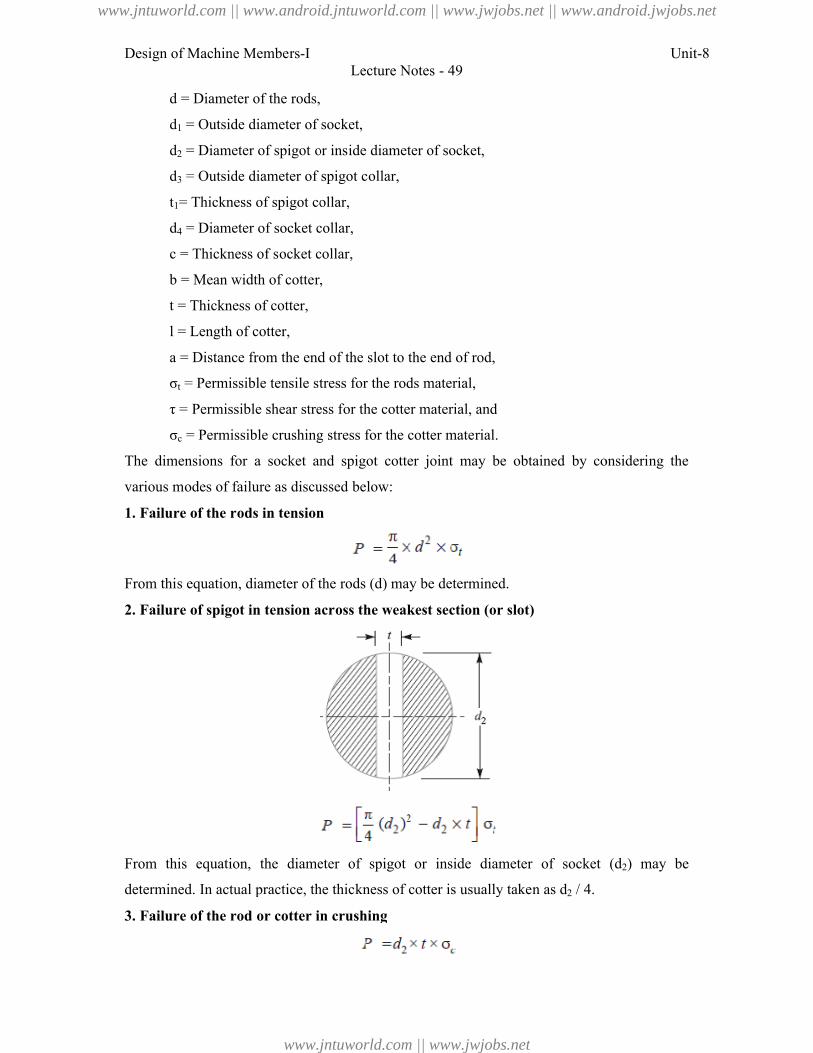
Design of Machine Members-I
d = Diameter of the rods,
d1 = Outside diameter of socket,
d2 = Diameter of spigot or inside diameter of socket,
d3 = Outside diameter of spigot co
t1= Thickness of spigot collar,
d4 = Diameter of socket collar,
c = Thickness of socket collar,
b = Mean width of cotter,
t = Thickness of cotter,
l = Length of cotter,
a = Distance from the end of the slot to the end of rod,
σt = Permissible tensile stress for the rods m
τ = Permissible shear stress for the cot
σc = Permissible crushing stress f
The dimensions for a socket and
various modes of failure as discussed
1. Failure of the rods in tension
From this equation, diameter of the
2. Failure of spigot in tension across the weakest section (or slot)
From this equation, the diameter
determined. In actual practice, the thickness of cotter is usually take
3. Failure of the rod or cotter in crushing
Lecture Notes - 49
= Diameter of the rods,
= Outside diameter of socket,
= Diameter of spigot or inside diameter of socket,
= Outside diameter of spigot collar,
= Thickness of spigot collar,
= Diameter of socket collar,
= Thickness of socket collar,
= Mean width of cotter,
= Distance from the end of the slot to the end of rod,
= Permissible tensile stress for the rods material,
Permissible shear stress for the cotter material, and
= Permissible crushing stress for the cotter material.
a socket and spigot cotter joint may be obtained by consid
as discussed below:
f the rods in tension
quation, diameter of the rods (d) may be determined.
Failure of spigot in tension across the weakest section (or slot)
the diameter of spigot or inside diameter of socket (
In actual practice, the thickness of cotter is usually taken as d2 / 4.
Failure of the rod or cotter in crushing
Unit-8
considering the
of socket (d2) may be
www.jntuworld.com || www.android.jntuworld.com || www.jwjobs.net || www.android.jwjobs.net
www.jntuworld.com || www.jwjobs.net
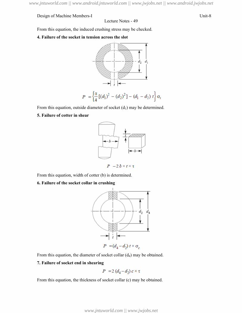
Design of Machine Members-I
From this equation, the induced crushing
4. Failure of the socket in tension
From this equation, outside diameter of socket (
5. Failure of cotter in shear
From this equation, width of cotter (
6. Failure of the socket collar in crushing
From this equation, the diameter of socke
7. Failure of socket end in shearing
From this equation, the thickness of
Lecture Notes - 49
quation, the induced crushing stress may be checked.
ocket in tension across the slot
this equation, outside diameter of socket (d1) may be determined.
quation, width of cotter (b) is determined.
ocket collar in crushing
quation, the diameter of socket collar (d4) may be obtained.
Failure of socket end in shearing
quation, the thickness of socket collar (c) may be obtained.
Unit-8
www.jntuworld.com || www.android.jntuworld.com || www.jwjobs.net || www.android.jwjobs.net
www.jntuworld.com || www.jwjobs.net
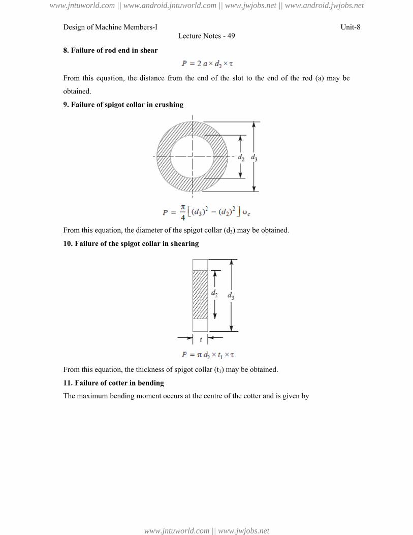
Design of Machine Members-I
8. Failure of rod end in shear
From this equation, the distance from
obtained.
9. Failure of spigot collar in crushing
From this equation, the diameter of t
10. Failure of the spigot collar in shearing
From this equation, the thickness of
11. Failure of cotter in bending
The maximum bending moment occurs at the centre of
Lecture Notes - 49
the distance from the end of the slot to the end of the rod (
Failure of spigot collar in crushing
quation, the diameter of the spigot collar (d3) may be obtained.
pigot collar in shearing
quation, the thickness of spigot collar (t1) may be obtained.
Failure of cotter in bending
m bending moment occurs at the centre of the cotter and is given by
Unit-8
end of the rod (a) may be
he centre of the cotter and is given by
www.jntuworld.com || www.android.jntuworld.com || www.jwjobs.net || www.android.jwjobs.net
www.jntuworld.com || www.jwjobs.net
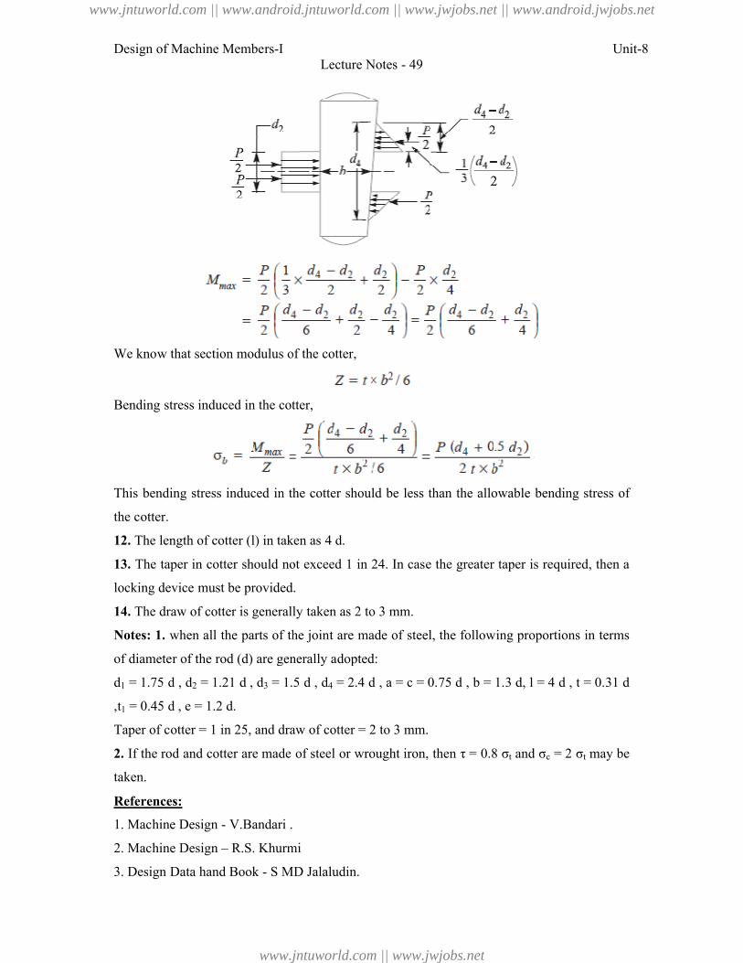
Design of Machine Members-I
We know that section modulus of the cotte
Bending stress induced in the cotter,
This bending stress induced in the
the cotter.
12. The length of cotter (l) in taken as 4
13. The taper in cotter should not excee
locking device must be provided.
14. The draw of cotter is generally taken as 2 to 3 mm.
Notes: 1. when all the parts of the joint
of diameter of the rod (d) are generally adopte
d1 = 1.75 d , d2 = 1.21 d , d3 = 1.5
,t1 = 0.45 d , e = 1.2 d.
Taper of cotter = 1 in 25, and draw of cotter =
2. If the rod and cotter are made of steel or wrought iron, then τ = 0.8 σ
taken.
References:
1. Machine Design - V.Bandari .
2. Machine Design – R.S. Khurmi
3. Design Data hand Book - S MD Jalaludin.
Lecture Notes - 49
hat section modulus of the cotter,
tress induced in the cotter,
induced in the cotter should be less than the allowable bending
) in taken as 4 d.
cotter should not exceed 1 in 24. In case the greater taper is required,
device must be provided.
The draw of cotter is generally taken as 2 to 3 mm.
the parts of the joint are made of steel, the following proportions
) are generally adopted:
= 1.5 d , d4 = 2.4 d , a = c = 0.75 d , b = 1.3 d, l = 4
= 1 in 25, and draw of cotter = 2 to 3 mm.
If the rod and cotter are made of steel or wrought iron, then τ = 0.8 σt and σc = 2 σ
V.Bandari .
R.S. Khurmi
S MD Jalaludin.
Unit-8
allowable bending stress of
taper is required, then a
ng proportions in terms
= 4 d , t = 0.31 d
= 2 σt may be
www.jntuworld.com || www.android.jntuworld.com || www.jwjobs.net || www.android.jwjobs.net
www.jntuworld.com || www.jwjobs.net
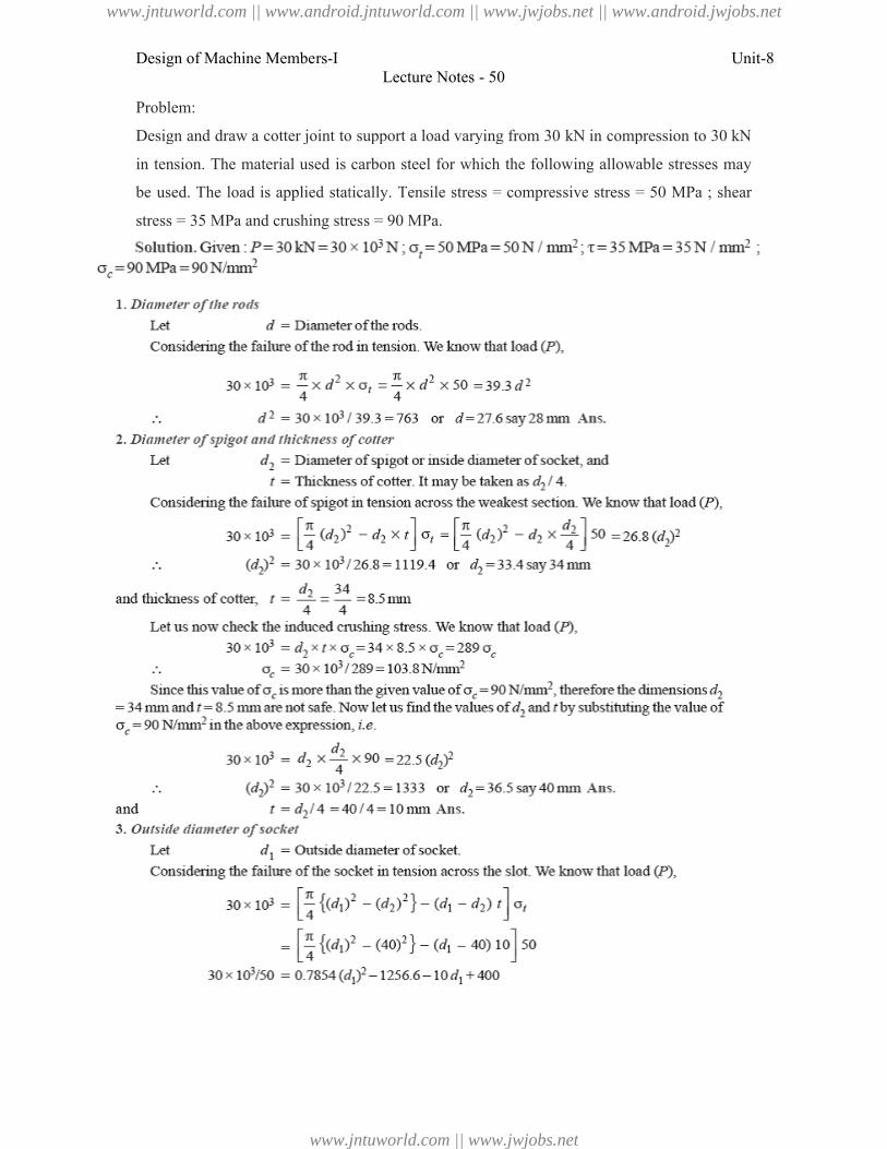
Design of Machine Members-I
Problem:
Design and draw a cotter joint to support a
in tension. The material used is carbon
be used. The load is applied statically.
stress = 35 MPa and crushing stress
Lecture Notes - 50
otter joint to support a load varying from 30 kN in compression
material used is carbon steel for which the following allowable stresses
applied statically. Tensile stress = compressive stress = 50 MPa
35 MPa and crushing stress = 90 MPa.
Unit-8
compression to 30 kN
allowable stresses may
50 MPa ; shear
www.jntuworld.com || www.android.jntuworld.com || www.jwjobs.net || www.android.jwjobs.net
www.jntuworld.com || www.jwjobs.net
Design of Machine Members-I
Lecture Notes - 50
Unit-8
www.jntuworld.com || www.android.jntuworld.com || www.jwjobs.net || www.android.jwjobs.net
www.jntuworld.com || www.jwjobs.net
Design of Machine Members-I
References:
1. Machine Design - V.Bandari .
2. Machine Design – R.S. Khurmi
3. Design Data hand Book - S MD Jalaludin.
Lecture Notes - 50
V.Bandari .
R.S. Khurmi
S MD Jalaludin.
Unit-8
www.jntuworld.com || www.android.jntuworld.com || www.jwjobs.net || www.android.jwjobs.net
www.jntuworld.com || www.jwjobs.net
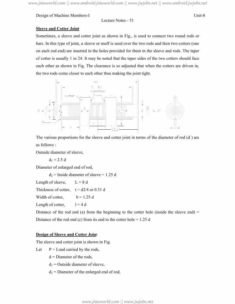
Design of Machine Members-I
Sleeve and Cotter Joint
Sometimes, a sleeve and cotter joint
bars. In this type of joint, a sleeve or
on each rod end) are inserted in the
of cotter is usually 1 in 24. It may be
each other as shown in Fig. The clearan
the two rods come closer to each other thus making the joi
The various proportions for the sleeve
as follows :
Outside diameter of sleeve,
d1 = 2.5 d
Diameter of enlarged end of rod,
d2 = Inside diameter of sleeve = 1.25
Length of sleeve, L = 8 d
Thickness of cotter, t = d2/4 or 0.31
Width of cotter, b = 1.25 d
Length of cotter, l = 4 d
Distance of the rod end (a) from the
Distance of the rod end (c) from its end t
Design of Sleeve and Cotter Join
The sleeve and cotter joint is shown in Fig.
Let P = Load carried by the rods,
d = Diameter of the rods,
d1 = Outside diameter of sleeve,
d2 = Diameter of the enlarged end
Lecture Notes - 51
d cotter joint as shown in Fig., is used to connect two round
joint, a sleeve or muff is used over the two rods and then two c
inserted in the holes provided for them in the sleeve and rods.
in 24. It may be noted that the taper sides of the two cotters should
The clearance is so adjusted that when the cotters are
to each other thus making the joint tight.
proportions for the sleeve and cotter joint in terms of the diameter of rod
r of enlarged end of rod,
e diameter of sleeve = 1.25 d
2/4 or 0.31 d
d
) from the beginning to the cotter hole (inside the sleeve
) from its end to the cotter hole = 1.25 d
and Cotter Joint
d cotter joint is shown in Fig.
= Load carried by the rods,
= Diameter of the rods,
= Outside diameter of sleeve,
= Diameter of the enlarged end of rod,
Unit-8
connect two round rods or
rods and then two cotters (one
sleeve and rods. The taper
two cotters should face
the cotters are driven in,
diameter of rod (d ) are
(inside the sleeve end) =
www.jntuworld.com || www.android.jntuworld.com || www.jwjobs.net || www.android.jwjobs.net
www.jntuworld.com || www.jwjobs.net
Design of Machine Members-I Unit-8
Lecture Notes - 51
t = Thickness of cotter,
l = Length of cotter,
b = Width of cotter,
a = Distance of the rod end from the beginning to the cotter hole (inside the sleeve
end),
c = Distance of the rod end from its end to the cotter hole,
σt , τ and σc = Permissible tensile, shear and crushing stresses respectively for the
material of the rods and cotter.
The dimensions for a sleeve and cotter joint may be obtained by considering the various
modes of failure as discussed below:
1. Failure of the rods in tension
The rods may fail in tension due to the tensile load P. We know that
From this equation, diameter of the rods (d) may be obtained.
2. Failure of the rod in tension across the weakest section (i.e. slot)
From this equation, the diameter of enlarged end of the rod (d2) may be obtained. The
thickness of cotter is usually taken as d2 / 4.
3. Failure of the rod or cotter in crushing
From this equation, the induced crushing stress may be checked.
4. Failure of sleeve in tension across the slot
From this equation, the outside diameter of sleeve (d1) may be obtained.
5. Failure of cotter in shear
From this equation, width of cotter (b) may be determined.
6. Failure of rod end in shear
From this equation, distance (a) may be determined.
www.jntuworld.com || www.android.jntuworld.com || www.jwjobs.net || www.android.jwjobs.net
www.jntuworld.com || www.jwjobs.net
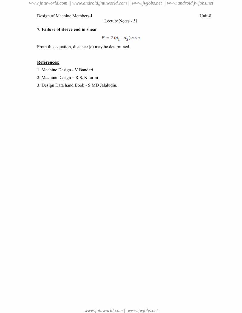
Design of Machine Members-I Unit-8
Lecture Notes - 51
7. Failure of sleeve end in shear
From this equation, distance (c) may be determined.
References:
1. Machine Design - V.Bandari .
2. Machine Design – R.S. Khurmi
3. Design Data hand Book - S MD Jalaludin.
www.jntuworld.com || www.android.jntuworld.com || www.jwjobs.net || www.android.jwjobs.net
www.jntuworld.com || www.jwjobs.net
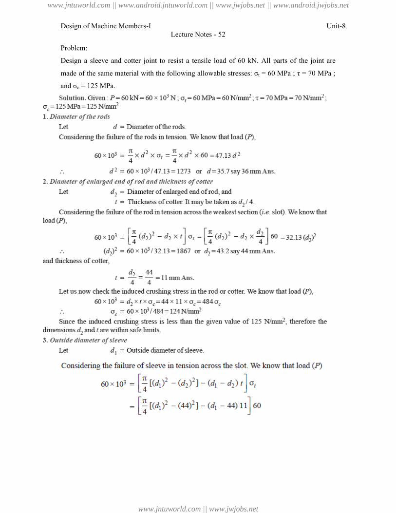
Design of Machine Members-I
Problem:
Design a sleeve and cotter joint to
made of the same material with t
and σc = 125 MPa.
Lecture Notes - 52
cotter joint to resist a tensile load of 60 kN. All parts of the
material with the following allowable stresses: σt = 60 MPa ;
Unit-8
All parts of the joint are
60 MPa ; τ = 70 MPa ;
www.jntuworld.com || www.android.jntuworld.com || www.jwjobs.net || www.android.jwjobs.net
www.jntuworld.com || www.jwjobs.net
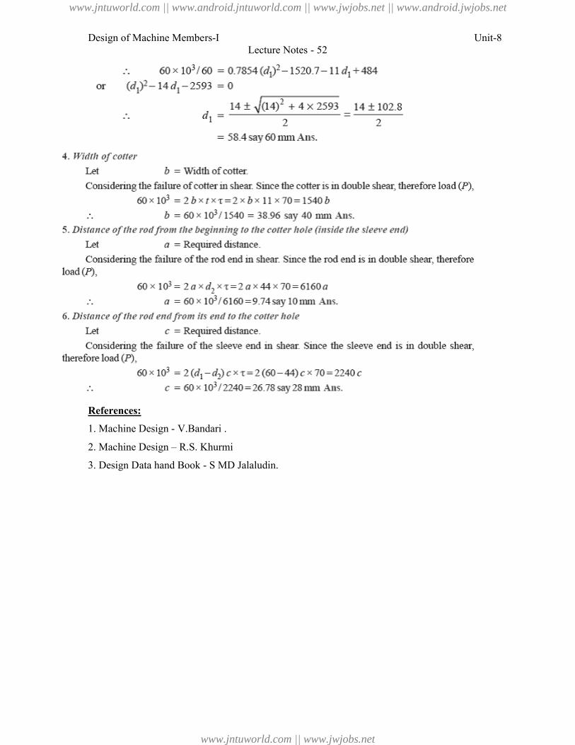
Design of Machine Members-I
References:
1. Machine Design - V.Bandari .
2. Machine Design – R.S. Khurmi
3. Design Data hand Book - S MD Jalaludin.
Lecture Notes - 52
V.Bandari .
R.S. Khurmi
S MD Jalaludin.
Unit-8
www.jntuworld.com || www.android.jntuworld.com || www.jwjobs.net || www.android.jwjobs.net
www.jntuworld.com || www.jwjobs.net
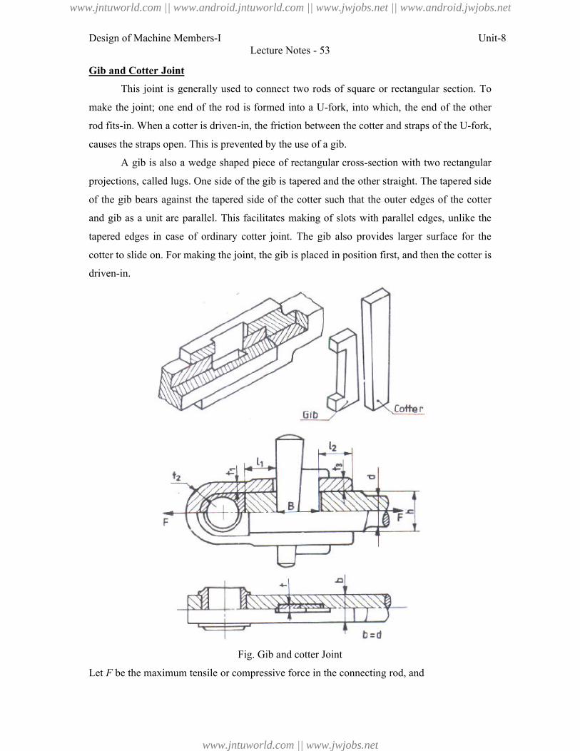
Design of Machine Members-I
Gib and Cotter Joint
This joint is generally use
make the joint; one end of the rod
rod fits-in. When a cotter is driven
causes the straps open. This is prevented by the use of a gib.
A gib is also a wedge shape
projections, called lugs. One side of
of the gib bears against the tapered
and gib as a unit are parallel. This
tapered edges in case of ordinary
cotter to slide on. For making the
driven-in.
Let F be the maximum tensile or compressive forc
Lecture Notes - 53
generally used to connect two rods of square or rectangular section.
end of the rod is formed into a U-fork, into which, the end of
otter is driven-in, the friction between the cotter and straps of the U
open. This is prevented by the use of a gib.
wedge shaped piece of rectangular cross-section with two rectangular
lugs. One side of the gib is tapered and the other straight. The tape
against the tapered side of the cotter such that the outer edges of
parallel. This facilitates making of slots with parallel edges,
inary cotter joint. The gib also provides larger surface
cotter to slide on. For making the joint, the gib is placed in position first, and then the cotter is
Fig. Gib and cotter Joint
um tensile or compressive force in the connecting rod, and
Unit-8
rectangular section. To
which, the end of the other
cotter and straps of the U-fork,
tion with two rectangular
traight. The tapered side
outer edges of the cotter
parallel edges, unlike the
provides larger surface for the
in position first, and then the cotter is
www.jntuworld.com || www.android.jntuworld.com || www.jwjobs.net || www.android.jwjobs.net
www.jntuworld.com || www.jwjobs.net
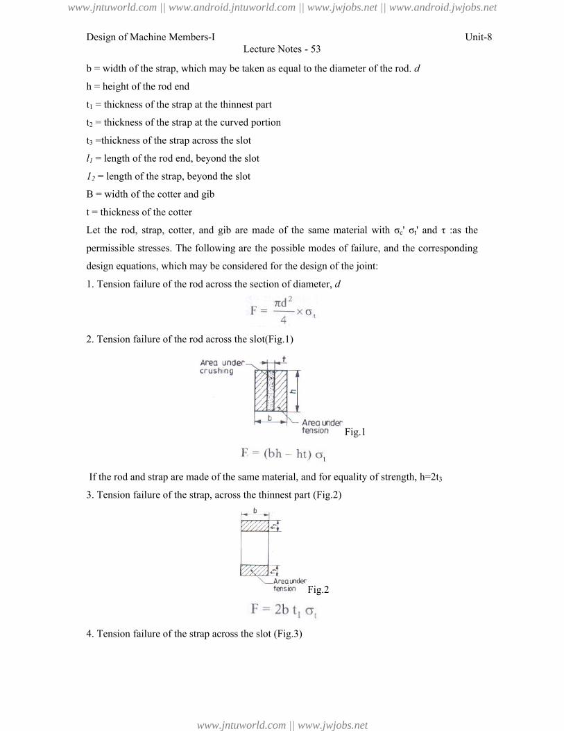
Design of Machine Members-I
b = width of the strap, which may be taken a
h = height of the rod end
t1 = thickness of the strap at the thinnest part
t2 = thickness of the strap at the curved portion
t3 =thickness of the strap across the slot
l1 = length of the rod end, beyond
12 = length of the strap, beyond the slot
B = width of the cotter and gib
t = thickness of the cotter
Let the rod, strap, cotter, and gib
permissible stresses. The following
design equations, which may be considered for the design of
1. Tension failure of the rod across the section of diamete
2. Tension failure of the rod across t
If the rod and strap are made of the same material, and f
3. Tension failure of the strap, across the t
4. Tension failure of the strap across the sl
Lecture Notes - 53
of the strap, which may be taken as equal to the diameter of the rod. d
= thickness of the strap at the thinnest part
= thickness of the strap at the curved portion
strap across the slot
beyond the slot
= length of the strap, beyond the slot
cotter, and gib are made of the same material with σc' σt' and
The following are the possible modes of failure, and the correspon
h may be considered for the design of the joint:
Tension failure of the rod across the section of diameter, d
of the rod across the slot(Fig.1)
Fig.1
the rod and strap are made of the same material, and for equality of strength, h=2t
ilure of the strap, across the thinnest part (Fig.2)
Fig.2
ilure of the strap across the slot (Fig.3)
Unit-8
' and τ :as the
failure, and the corresponding
h=2t3
www.jntuworld.com || www.android.jntuworld.com || www.jwjobs.net || www.android.jwjobs.net
www.jntuworld.com || www.jwjobs.net
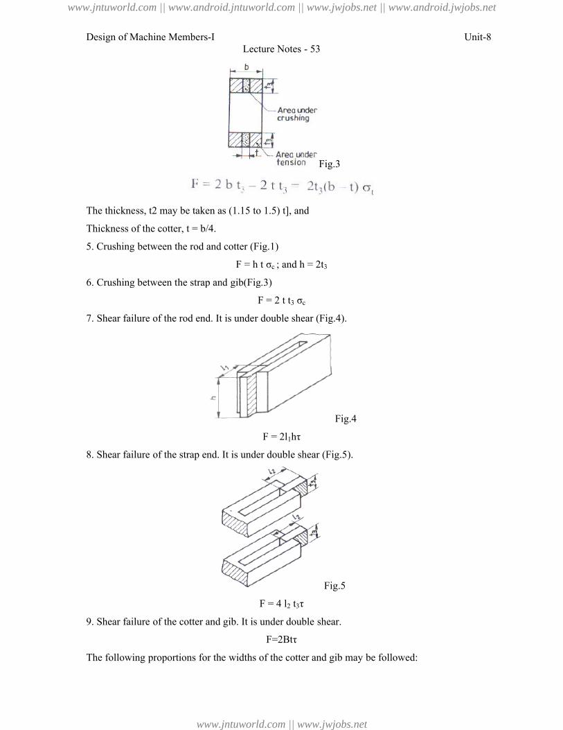
Design of Machine Members-I
The thickness, t2 may be taken as (1.15 to 1.
Thickness of the cotter, t = b/4.
5. Crushing between the rod and cotter (Fig.1)
6. Crushing between the strap and gib(Fig.
7. Shear failure of the rod end. It is under
8. Shear failure of the strap end.
9. Shear failure of the cotter and gib. It is under double shea
The following proportions for the widt
Lecture Notes - 53
Fig.3
ss, t2 may be taken as (1.15 to 1.5) t], and
ing between the rod and cotter (Fig.1)
F = h t σc ; and h = 2t3
Crushing between the strap and gib(Fig.3)
F = 2 t t3 σc
f the rod end. It is under double shear (Fig.4).
Fig.4
F = 2l1hτ
lure of the strap end. It is under double shear (Fig.5).
Fig.5
F = 4 l2 t3τ
lure of the cotter and gib. It is under double shear.
F=2Btτ
for the widths of the cotter and gib may be followed:
Unit-8
www.jntuworld.com || www.android.jntuworld.com || www.jwjobs.net || www.android.jwjobs.net
www.jntuworld.com || www.jwjobs.net
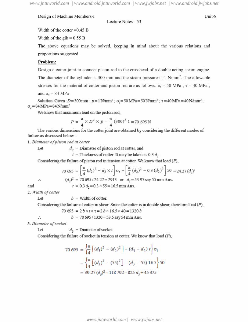
Design of Machine Members-I
Width of the cotter =0.45 B
Width of the gib = 0.55 B
The above equations may be solved,
proportions suggested.
Problem:
Design a cotter joint to connect
The diameter of the cylinder is 300
stresses for the material of cotter and
and σc = 84 MPa
Lecture Notes - 53
may be solved, keeping in mind about the various relations
to connect piston rod to the crosshead of a double acting steam
cylinder is 300 mm and the steam pressure is 1 N/mm2. The
material of cotter and piston rod are as follows: σt = 50 MPa ;
Unit-8
the various relations and
steam engine.
. The allowable
MPa ; τ = 40 MPa ;
www.jntuworld.com || www.android.jntuworld.com || www.jwjobs.net || www.android.jwjobs.net
www.jntuworld.com || www.jwjobs.net
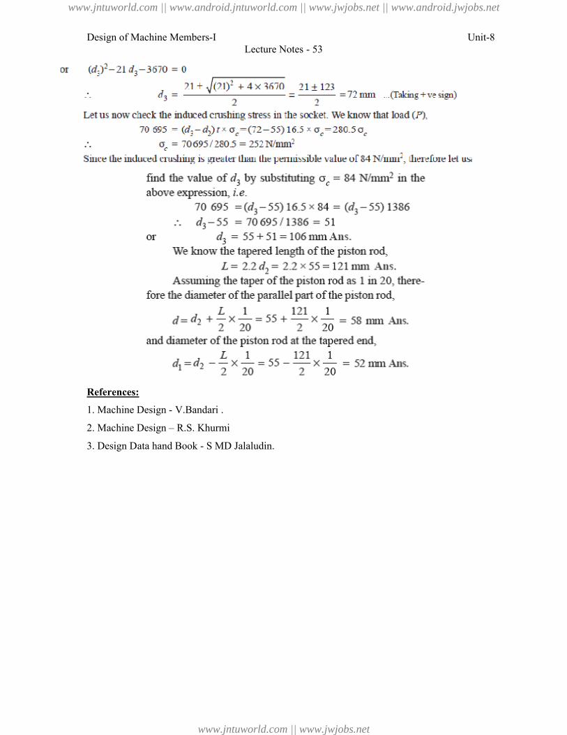
Design of Machine Members-I
References:
1. Machine Design - V.Bandari .
2. Machine Design – R.S. Khurmi
3. Design Data hand Book - S MD Jalaludin.
Lecture Notes - 53
V.Bandari .
R.S. Khurmi
S MD Jalaludin.
Unit-8
www.jntuworld.com || www.android.jntuworld.com || www.jwjobs.net || www.android.jwjobs.net
www.jntuworld.com || www.jwjobs.net
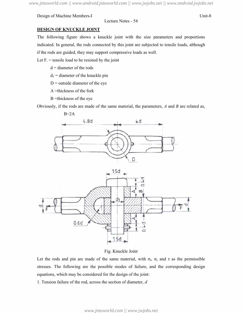
Design of Machine Members-I
DESIGN OF KNUCKLE JOINT
The following figure shows a knuckle
indicated. In general, the rods connected
if the rods are guided, they may support
Let F. = tensile load to be resisted
d = diameter of the rods
d1 = diameter of the knuckle pin
D = outside diameter of the eye
A =thickness of the fork
B =thickness of the eye
Obviously, if the rods are made of
B=2A
Let the rods and pin are made of
stresses. The following are the possible
equations, which may be considered for t
1. Tension failure of the rod, across the section of diamete
Lecture Notes - 54
KNUCKLE JOINT
shows a knuckle joint with the size parameters and proportions
the rods connected by this joint are subjected to tensile loads,
may support compressive loads as well.
to be resisted by the joint
= diameter of the knuckle pin
e diameter of the eye
are made of the same material, the parameters, A and B are
Fig. Knuckle Joint
are made of the same material, with σt, σc and τ as the permissible
following are the possible modes of failure, and the corresponding
may be considered for the design of the joint:
Tension failure of the rod, across the section of diameter, d
Unit-8
parameters and proportions
to tensile loads, although
are related as,
as the permissible
the corresponding design
www.jntuworld.com || www.android.jntuworld.com || www.jwjobs.net || www.android.jwjobs.net
www.jntuworld.com || www.jwjobs.net
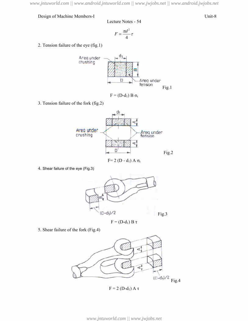
Design of Machine Members-I
2. Tension failure of the eye (fig.1)
3. Tension failure of the fork (fig.2)
4. Shear failure of the eye (Fig.3)
5. Shear failure of the fork (Fig.4)
Lecture Notes - 54
4
2d
F ilure of the eye (fig.1)
Fig.1
F = (D-d1) B σt
ilure of the fork (fig.2)
Fig.2
F= 2 (D - d1) A σt
Fig.3
F = (D-d1) B τ
lure of the fork (Fig.4)
Fig.4
F = 2 (D-d1) A τ
Unit-8
www.jntuworld.com || www.android.jntuworld.com || www.jwjobs.net || www.android.jwjobs.net
www.jntuworld.com || www.jwjobs.net
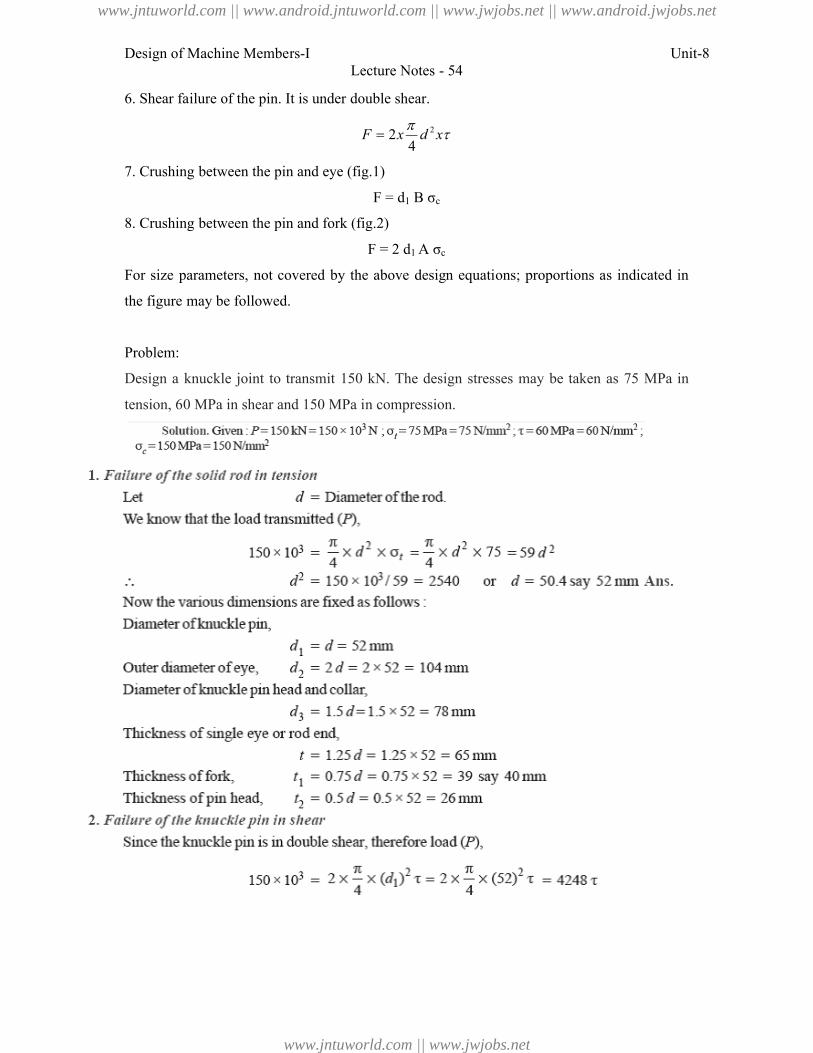
Design of Machine Members-I
6. Shear failure of the pin. It is under double shear.
7. Crushing between the pin and
8. Crushing between the pin and fork (fig.2)
For size parameters, not covered by
the figure may be followed.
Problem:
Design a knuckle joint to transmit
tension, 60 MPa in shear and 150 M
Lecture Notes - 54
lure of the pin. It is under double shear.
xdxF
2
42
ing between the pin and eye (fig.1)
F = d1 B σc
ing between the pin and fork (fig.2)
F = 2 d1 A σc
not covered by the above design equations; proportions as indicated
joint to transmit 150 kN. The design stresses may be taken as
60 MPa in shear and 150 MPa in compression.
Unit-8
proportions as indicated in
be taken as 75 MPa in
www.jntuworld.com || www.android.jntuworld.com || www.jwjobs.net || www.android.jwjobs.net
www.jntuworld.com || www.jwjobs.net
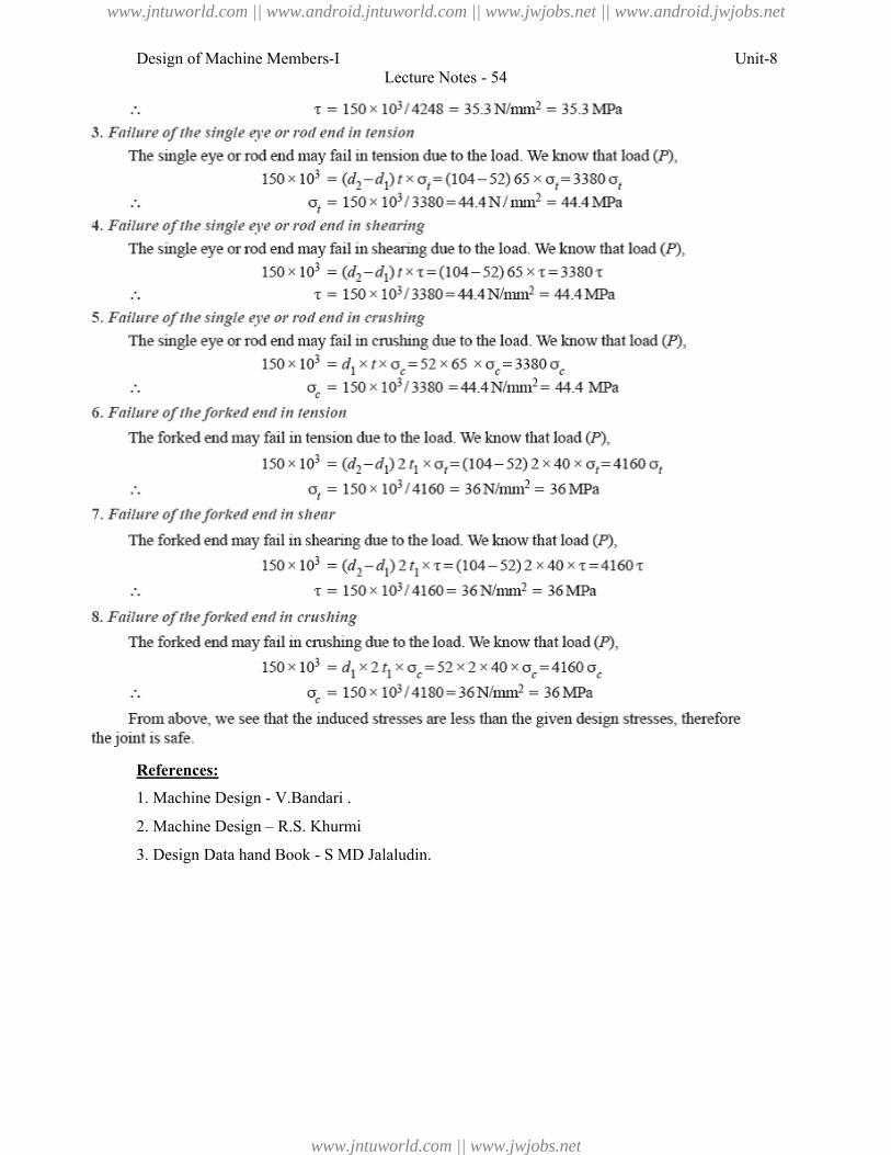
Design of Machine Members-I
References:
1. Machine Design - V.Bandari .
2. Machine Design – R.S. Khurmi
3. Design Data hand Book - S MD Jalaludin.
Lecture Notes - 54
V.Bandari .
R.S. Khurmi
S MD Jalaludin.
Unit-8
www.jntuworld.com || www.android.jntuworld.com || www.jwjobs.net || www.android.jwjobs.net
www.jntuworld.com || www.jwjobs.net
Design of Machine Members-I Unit-8
Lecture Notes - 55
Shafts:
A shaft is a rotating machine element which is used to transmit power from one place to
another. The power is delivered to the shaft by some tangential force and the resultant torque
(or twisting moment) set up within the shaft permits the power to be transferred to various
machines linked up to the shaft. In order to transfer the power from one shaft to another, the
various members such as pulleys, gears etc., are mounted on it. These members along with
the forces exerted upon them causes the shaft to bending.
In other words, we may say that a shaft is used for the transmission of torque and
bending moment. The various members are mounted on the shaft by means of keys or
splines. The shafts are usually cylindrical, but may be square or cross-shaped in section. They
are solid in cross-section but sometimes hollow shafts are also used. An axle, though similar
in shape to the shaft, is a stationary machine element and is used for the transmission of
bending moment only. It simply acts as a support for some rotating body such as hoisting
drum, a car wheel or a rope sheave. A spindle is a short shaft that imparts motion either to a
cutting tool (e.g. drill press spindles) or to a work piece (e.g. lathe spindles).
Types of Shafts
The following two types of shafts are important from the subject point of view:
1. Transmission shafts. These shafts transmit power between the source and the machines
absorbing power. The counter shafts, line shafts, over head shafts and all factory shafts are
transmission shafts. Since these shafts carry machine parts such as pulleys, gears etc.,
therefore they are subjected to bending in addition to twisting.
2. Machine shafts. These shafts form an integral part of the machine itself. The crank shaft is
an example of machine shaft.
Stresses in Shafts
The following stresses are induced in the shafts:
1. Shear stresses due to the transmission of torque (i.e. due to torsional load).
2. Bending stresses (tensile or compressive) due to the forces acting upon machine elements
like gears, pulleys etc. as well as due to the weight of the shaft itself.
3. Stresses due to combined torsional and bending loads.
Design of Shafts
The shafts may be designed on the basis of
1. Strength, and 2. Rigidity and stiffness.
www.jntuworld.com || www.android.jntuworld.com || www.jwjobs.net || www.android.jwjobs.net
www.jntuworld.com || www.jwjobs.net
Design of Machine Members-I Unit-8
Lecture Notes - 55
In designing shafts on the basis of strength, the following cases may be considered:
(a) Shafts subjected to twisting moment or torque only,
(b) Shafts subjected to bending moment only,
(c) Shafts subjected to combined twisting and bending moments, and
(d) Shafts subjected to axial loads in addition to combined torsional and bending loads.
Shafts Subjected to Twisting Moment Only
a) Solid shaft:
When the shaft is subjected to a twisting moment (or torque) only, then the diameter of the
shaft may be obtained by using the torsion equation. We know that
T
J r
Where T = Twisting moment (or torque) acting upon the shaft,
J = Polar moment of inertia of the shaft about the axis of rotation,
τ = Torsional shear stress, and
r = Distance from neutral axis to the outer most fibre
= d / 2; where d is the diameter of the shaft.
We know that for round solid shaft, polar moment of inertia,
4
32J d
Then we get,3
16
dT
From this equation, diameter of the solid shaft (d) may be obtained.
b) Hollow Shaft:
We also know that for hollow shaft, polar moment of inertia,
4 4
0( ) ( )32
iJ d d
Where do and di = Outside and inside diameter of the shaft, and r = d0 / 2.
Substituting these values in equation (i), we have
Let k = Ratio of inside diameter and outside diameter of the shaft = di / do
Now the equation (iii) may be written as
www.jntuworld.com || www.android.jntuworld.com || www.jwjobs.net || www.android.jwjobs.net
www.jntuworld.com || www.jwjobs.net
Design of Machine Members-I Unit-8
Lecture Notes - 55
From the equations, the outside and inside diameter of a hollow shaft may be determined.
It may be noted that
1. The hollow shafts are usually used in marine work. These shafts are stronger per kg of
material and they may be forged on a mandrel, thus making the material more homogeneous
than would be possible for a solid shaft. When a hollow shaft is to be made equal in strength
to a solid shaft, the twisting moment of both the shafts must be same. In other words, for the
same material of both the shafts,
2. The twisting moment (T) may be obtained by using the following relation:
We know that the power transmitted (in watts) by the shaft,
Where T = Twisting moment in N-m, and
N = Speed of the shaft in r.p.m.
3. In case of belt drives, the twisting moment (T) is given by
T = (T1 – T2) R
Where T1 and T2 = Tensions in the tight side and slack side of the belt respectively, and R =
Radius of the pulley.
Shafts Subjected to Bending Moment Only
a) Solid Shaft:
When the shaft is subjected to a bending moment only, then the maximum stress (tensile or
compressive) is given by the bending equation. We know that
Where M = Bending moment,
I = Moment of inertia of cross-sectional area of the shaft about the axis of rotation,
σb = Bending stress, and
y = Distance from neutral axis to the outer-most fibre.
www.jntuworld.com || www.android.jntuworld.com || www.jwjobs.net || www.android.jwjobs.net
www.jntuworld.com || www.jwjobs.net
Design of Machine Members-I Unit-8
Lecture Notes - 55
We know that for a round solid shaft, moment of inertia,
Substituting these values in equation
From this equation, diameter of the solid shaft (d) may be obtained.
b) Hollow Shaft:
We also know that for a hollow shaft, moment of inertia,
And y = d0/ 2
Again substituting these values in equation, we have
From this equation, the outside diameter of the shaft (do) may be obtained.
Shafts Subjected to Combined Twisting Moment and Bending Moment
When the shaft is subjected to combined twisting moment and bending moment, then the
shaft must be designed on the basis of the two moments simultaneously. Various theories
have been suggested to account for the elastic failure of the materials when they are subjected
to various types of combined stresses. The following two theories are important from the
subject point of view:
1. Maximum shear stress theory or Guest's theory. It is used for ductile materials such as mild
steel.
2. Maximum normal stress theory or Rankine’s theory. It is used for brittle materials such as
cast iron.
Let τ = Shear stress induced due to twisting moment, and
σb = Bending stress (tensile or compressive) induced due to bending moment.
a) Solid Shaft:
According to maximum shear stress theory, the maximum shear stress in the shaft,
www.jntuworld.com || www.android.jntuworld.com || www.jwjobs.net || www.android.jwjobs.net
www.jntuworld.com || www.jwjobs.net
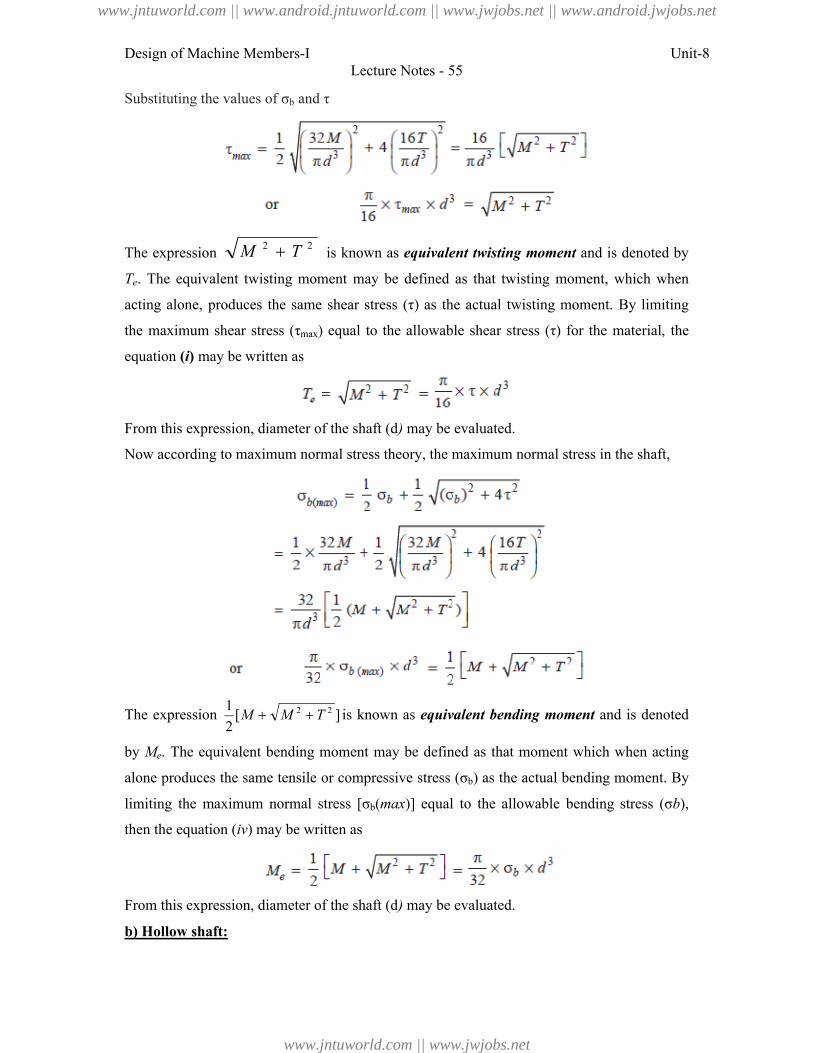
Design of Machine Members-I Unit-8
Lecture Notes - 55
Substituting the values of σb and τ
The expression 22 TM is known as equivalent twisting moment and is denoted by
Te. The equivalent twisting moment may be defined as that twisting moment, which when
acting alone, produces the same shear stress (τ) as the actual twisting moment. By limiting
the maximum shear stress (τmax) equal to the allowable shear stress (τ) for the material, the
equation (i) may be written as
From this expression, diameter of the shaft (d) may be evaluated.
Now according to maximum normal stress theory, the maximum normal stress in the shaft,
The expression ][2
1 22 TMM is known as equivalent bending moment and is denoted
by Me. The equivalent bending moment may be defined as that moment which when acting
alone produces the same tensile or compressive stress (σb) as the actual bending moment. By
limiting the maximum normal stress [σb(max)] equal to the allowable bending stress (σb),
then the equation (iv) may be written as
From this expression, diameter of the shaft (d) may be evaluated.
b) Hollow shaft:
www.jntuworld.com || www.android.jntuworld.com || www.jwjobs.net || www.android.jwjobs.net
www.jntuworld.com || www.jwjobs.net
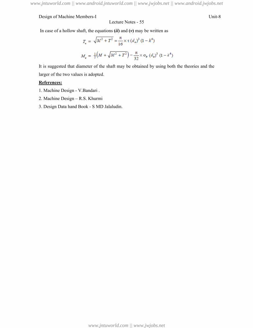
Design of Machine Members-I Unit-8
Lecture Notes - 55
In case of a hollow shaft, the equations (ii) and (v) may be written as
It is suggested that diameter of the shaft may be obtained by using both the theories and the
larger of the two values is adopted.
References:
1. Machine Design - V.Bandari .
2. Machine Design – R.S. Khurmi
3. Design Data hand Book - S MD Jalaludin.
www.jntuworld.com || www.android.jntuworld.com || www.jwjobs.net || www.android.jwjobs.net
www.jntuworld.com || www.jwjobs.net
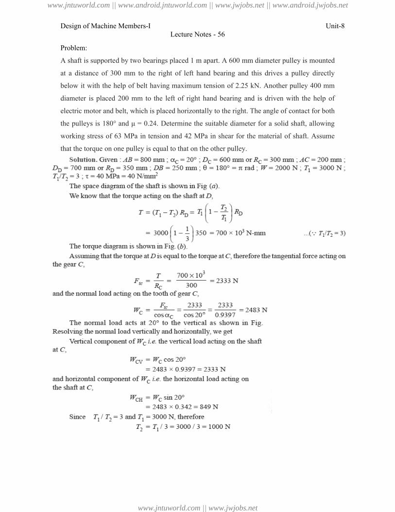
Design of Machine Members-I
Problem:
A shaft is supported by two bearings placed
at a distance of 300 mm to the right
below it with the help of belt having
diameter is placed 200 mm to the
electric motor and belt, which is placed horizontall
the pulleys is 180° and μ = 0.24. Determi
working stress of 63 MPa in tension
that the torque on one pulley is equal to that on the othe
Lecture Notes - 56
d by two bearings placed 1 m apart. A 600 mm diameter pulley is
mm to the right of left hand bearing and this drives a pulley
help of belt having maximum tension of 2.25 kN. Another pulley
200 mm to the left of right hand bearing and is driven with the
motor and belt, which is placed horizontally to the right. The angle of contact for both
0.24. Determine the suitable diameter for a solid shaft,
MPa in tension and 42 MPa in shear for the material of shaft.
pulley is equal to that on the other pulley.
Unit-8
pulley is mounted
drives a pulley directly
Another pulley 400 mm
driven with the help of
y to the right. The angle of contact for both
for a solid shaft, allowing
material of shaft. Assume
www.jntuworld.com || www.android.jntuworld.com || www.jwjobs.net || www.android.jwjobs.net
www.jntuworld.com || www.jwjobs.net
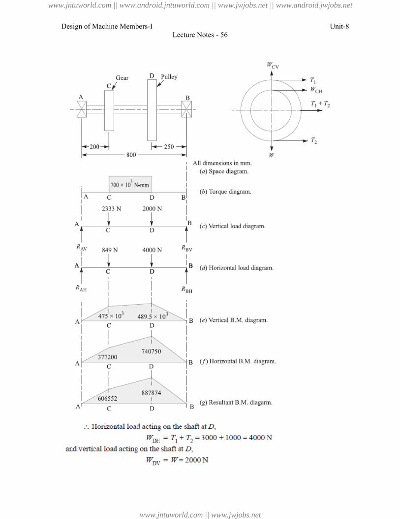
Design of Machine Members-I
Lecture Notes - 56
Unit-8
www.jntuworld.com || www.android.jntuworld.com || www.jwjobs.net || www.android.jwjobs.net
www.jntuworld.com || www.jwjobs.net
Design of Machine Members-I
Lecture Notes - 56
Unit-8
www.jntuworld.com || www.android.jntuworld.com || www.jwjobs.net || www.android.jwjobs.net
www.jntuworld.com || www.jwjobs.net
Design of Machine Members-I
Problem:
A steel solid shaft transmitting 15
apart and has two gears keyed to it.
100 mm to the left of the right hand
gear having 100 teeth of 5 mm modul
and receives power in a vertical direction from below.
shear, determine the diameter of the shaft.
Lecture Notes - 56
ansmitting 15 kW at 200 r.p.m. is supported on two bearings
gears keyed to it. The pinion having 30 teeth of 5 mm module
the right hand bearing and delivers power horizontally to the
of 5 mm module is located 150 mm to the right of the left hand
power in a vertical direction from below. Using an allowable stress of 54 MPa in
the diameter of the shaft.
Unit-8
on two bearings 750 mm
5 mm module is located
horizontally to the right. The
right of the left hand bearing
ing an allowable stress of 54 MPa in
www.jntuworld.com || www.android.jntuworld.com || www.jwjobs.net || www.android.jwjobs.net
www.jntuworld.com || www.jwjobs.net
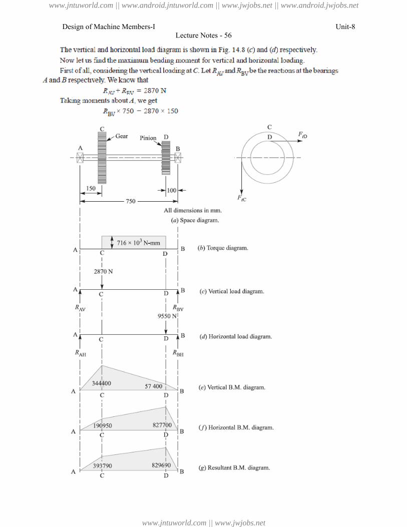
Design of Machine Members-I
Lecture Notes - 56
Unit-8
www.jntuworld.com || www.android.jntuworld.com || www.jwjobs.net || www.android.jwjobs.net
www.jntuworld.com || www.jwjobs.net
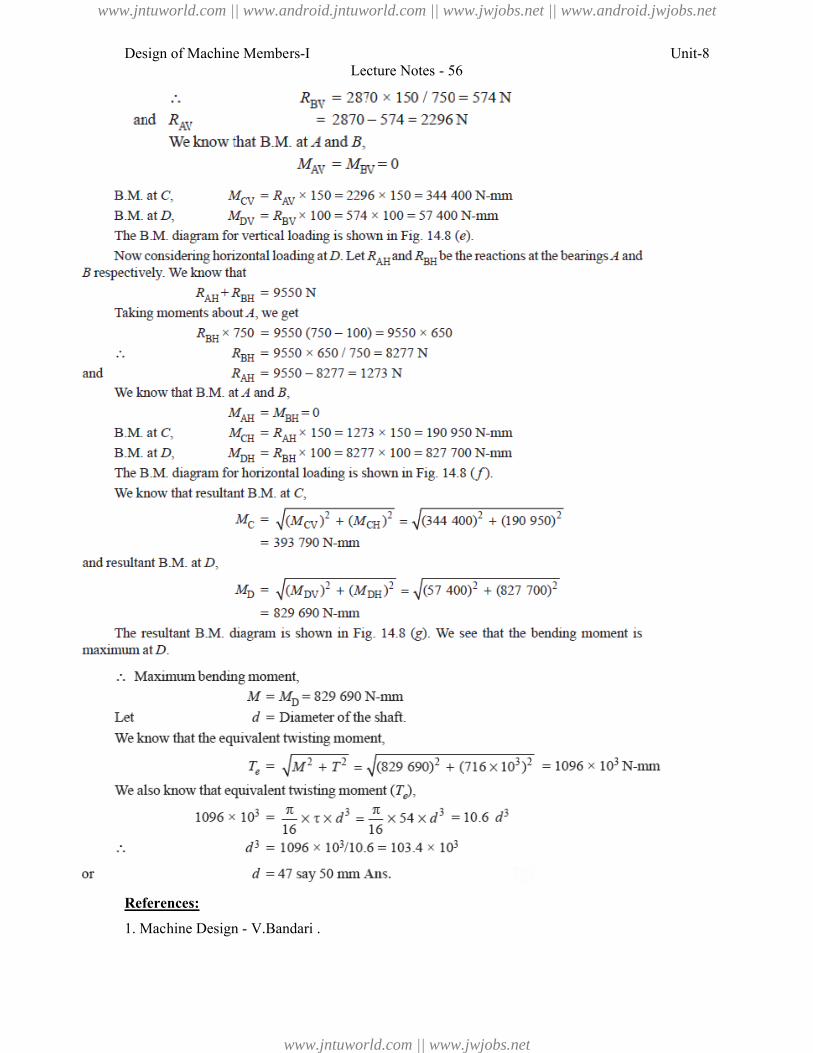
Design of Machine Members-I
References:
1. Machine Design - V.Bandari .
Lecture Notes - 56
V.Bandari .
Unit-8
www.jntuworld.com || www.android.jntuworld.com || www.jwjobs.net || www.android.jwjobs.net
www.jntuworld.com || www.jwjobs.net
Design of Machine Members-I Unit-8
Lecture Notes - 56
2. Machine Design – R.S. Khurmi
3. Design Data hand Book - S MD Jalaludin.
www.jntuworld.com || www.android.jntuworld.com || www.jwjobs.net || www.android.jwjobs.net
www.jntuworld.com || www.jwjobs.net
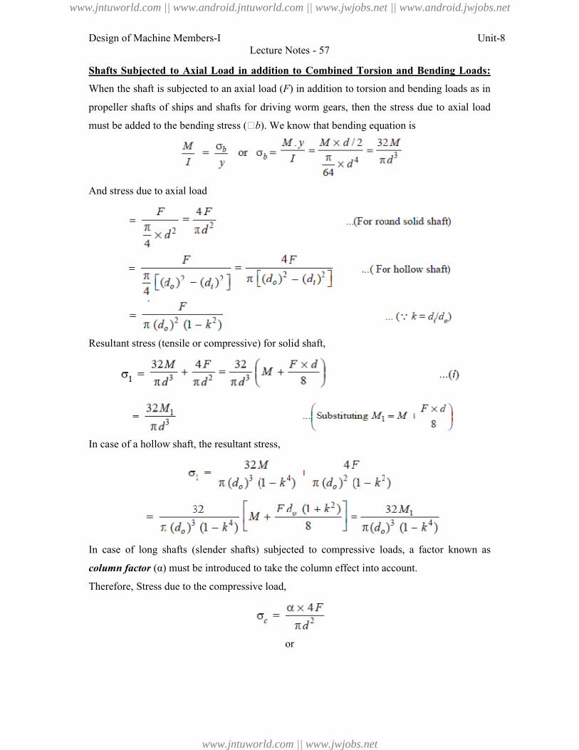
Design of Machine Members-I
Shafts Subjected to Axial Load in
When the shaft is subjected to an axial
propeller shafts of ships and shafts
must be added to the bending stress (
And stress due to axial load
Resultant stress (tensile or compressive) for so
In case of a hollow shaft, the resultant stres
In case of long shafts (slender shafts)
column factor (α) must be introduced to take the column effect into account.
Therefore, Stress due to the compressive load,
Lecture Notes - 57
Axial Load in addition to Combined Torsion and Bending
ubjected to an axial load (F) in addition to torsion and bending
ships and shafts for driving worm gears, then the stress due to
added to the bending stress (b). We know that bending equation is
stress (tensile or compressive) for solid shaft,
ow shaft, the resultant stress,
shafts (slender shafts) subjected to compressive loads, a factor
(α) must be introduced to take the column effect into account.
Stress due to the compressive load,
or
Unit-8
Torsion and Bending Loads:
and bending loads as in
due to axial load
loads, a factor known as
www.jntuworld.com || www.android.jntuworld.com || www.jwjobs.net || www.android.jwjobs.net
www.jntuworld.com || www.jwjobs.net
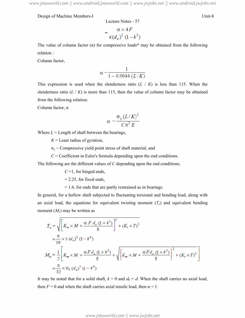
Design of Machine Members-I Unit-8
Lecture Notes - 57
The value of column factor (α) for compressive loads* may be obtained from the following
relation :
Column factor,
This expression is used when the slenderness ratio (L / K) is less than 115. When the
slenderness ratio (L / K) is more than 115, then the value of column factor may be obtained
from the following relation:
Column factor, α
Where L = Length of shaft between the bearings,
K = Least radius of gyration,
σy = Compressive yield point stress of shaft material, and
C = Coefficient in Euler's formula depending upon the end conditions.
The following are the different values of C depending upon the end conditions.
C =1, for hinged ends,
= 2.25, for fixed ends,
= 1.6, for ends that are partly restrained as in bearings.
In general, for a hollow shaft subjected to fluctuating torsional and bending load, along with
an axial load, the equations for equivalent twisting moment (Te) and equivalent bending
moment (Me) may be written as
It may be noted that for a solid shaft, k = 0 and d0 = d. When the shaft carries no axial load,
then F = 0 and when the shaft carries axial tensile load, then α = 1.
www.jntuworld.com || www.android.jntuworld.com || www.jwjobs.net || www.android.jwjobs.net
www.jntuworld.com || www.jwjobs.net

Design of Machine Members-I Unit-8
Lecture Notes - 57
References:
1. Machine Design - V.Bandari .
2. Machine Design – R.S. Khurmi
3. Design Data hand Book - S MD Jalaludin.
www.jntuworld.com || www.android.jntuworld.com || www.jwjobs.net || www.android.jwjobs.net
www.jntuworld.com || www.jwjobs.net
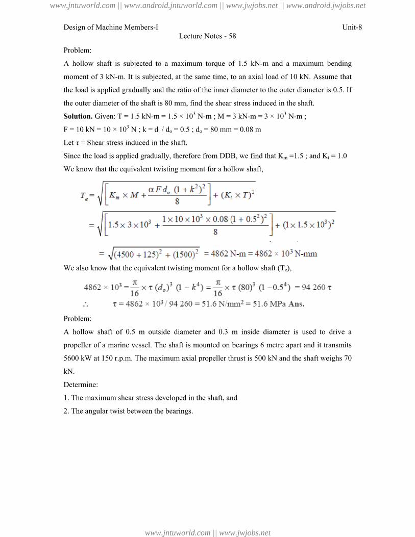
Design of Machine Members-I
Problem:
A hollow shaft is subjected to a maximum
moment of 3 kN-m. It is subjected,
the load is applied gradually and the ratio
the outer diameter of the shaft is 80 mm, find the shear
Solution. Given: T = 1.5 kN-m = 1.5 × 10
F = 10 kN = 10 × 103
N ; k = di /
Let τ = Shear stress induced in the shaft.
Since the load is applied gradually, theref
We know that the equivalent twisting moment for a
We also know that the equivalent twis
Problem:
A hollow shaft of 0.5 m outside
propeller of a marine vessel. The shaft
5600 kW at 150 r.p.m. The maximum axia
kN.
Determine:
1. The maximum shear stress developed in the shaft, and
2. The angular twist between the bearings.
Lecture Notes - 58
subjected to a maximum torque of 1.5 kN-m and a maximum
It is subjected, at the same time, to an axial load of 10 kN. Assume
gradually and the ratio of the inner diameter to the outer diameter is
he shaft is 80 mm, find the shear stress induced in the shaft.
m = 1.5 × 10³
N-m ; M = 3 kN-m = 3 × 10³
N-m ;
/ do = 0.5 ; do = 80 mm = 0.08 m
τ = Shear stress induced in the shaft.
d is applied gradually, therefore from DDB, we find that Km =1.5 ; and
hat the equivalent twisting moment for a hollow shaft,
o know that the equivalent twisting moment for a hollow shaft (Te),
0.5 m outside diameter and 0.3 m inside diameter is used
vessel. The shaft is mounted on bearings 6 metre apart and it
t 150 r.p.m. The maximum axial propeller thrust is 500 kN and the shaft we
ximum shear stress developed in the shaft, and
ngular twist between the bearings.
Unit-8
and a maximum bending
load of 10 kN. Assume that
outer diameter is 0.5. If
d in the shaft.
=1.5 ; and Kt = 1.0
diameter is used to drive a
metre apart and it transmits
kN and the shaft weighs 70
www.jntuworld.com || www.android.jntuworld.com || www.jwjobs.net || www.android.jwjobs.net
www.jntuworld.com || www.jwjobs.net
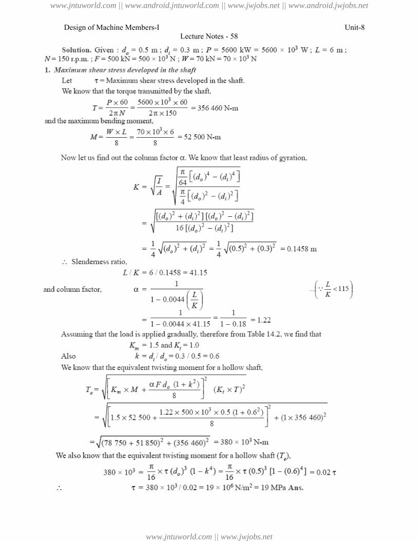
Design of Machine Members-I
Lecture Notes - 58
Unit-8
www.jntuworld.com || www.android.jntuworld.com || www.jwjobs.net || www.android.jwjobs.net
www.jntuworld.com || www.jwjobs.net
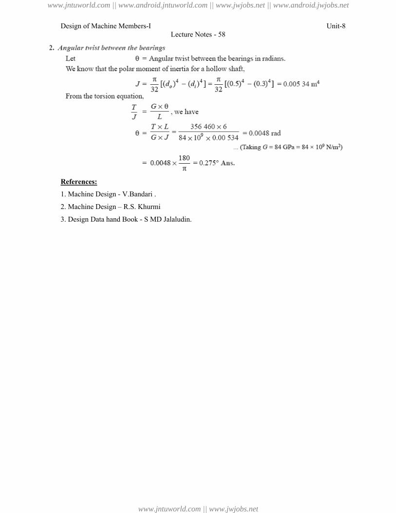
Design of Machine Members-I
References:
1. Machine Design - V.Bandari .
2. Machine Design – R.S. Khurmi
3. Design Data hand Book - S MD Jalaludin
Lecture Notes - 58
V.Bandari .
R.S. Khurmi
S MD Jalaludin.
Unit-8
www.jntuworld.com || www.android.jntuworld.com || www.jwjobs.net || www.android.jwjobs.net
www.jntuworld.com || www.jwjobs.net
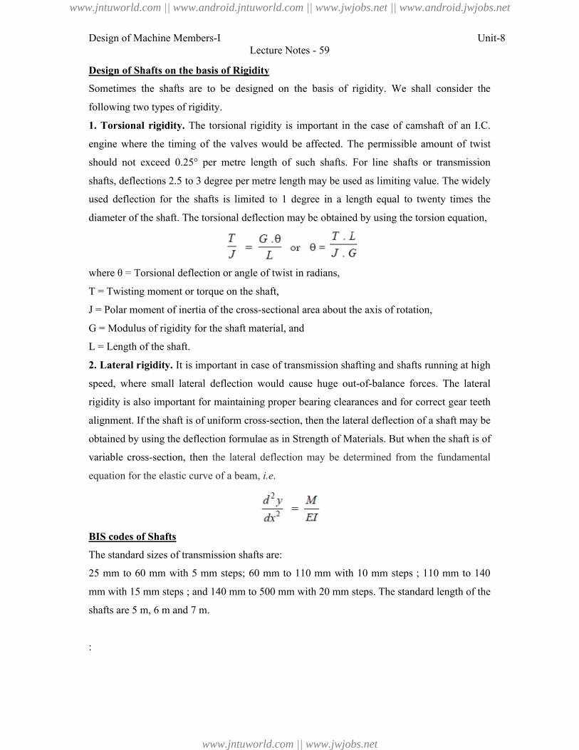
Design of Machine Members-I Unit-8
Lecture Notes - 59
Design of Shafts on the basis of Rigidity
Sometimes the shafts are to be designed on the basis of rigidity. We shall consider the
following two types of rigidity.
1. Torsional rigidity. The torsional rigidity is important in the case of camshaft of an I.C.
engine where the timing of the valves would be affected. The permissible amount of twist
should not exceed 0.25° per metre length of such shafts. For line shafts or transmission
shafts, deflections 2.5 to 3 degree per metre length may be used as limiting value. The widely
used deflection for the shafts is limited to 1 degree in a length equal to twenty times the
diameter of the shaft. The torsional deflection may be obtained by using the torsion equation,
where θ = Torsional deflection or angle of twist in radians,
T = Twisting moment or torque on the shaft,
J = Polar moment of inertia of the cross-sectional area about the axis of rotation,
G = Modulus of rigidity for the shaft material, and
L = Length of the shaft.
2. Lateral rigidity. It is important in case of transmission shafting and shafts running at high
speed, where small lateral deflection would cause huge out-of-balance forces. The lateral
rigidity is also important for maintaining proper bearing clearances and for correct gear teeth
alignment. If the shaft is of uniform cross-section, then the lateral deflection of a shaft may be
obtained by using the deflection formulae as in Strength of Materials. But when the shaft is of
variable cross-section, then the lateral deflection may be determined from the fundamental
equation for the elastic curve of a beam, i.e.
BIS codes of Shafts
The standard sizes of transmission shafts are:
25 mm to 60 mm with 5 mm steps; 60 mm to 110 mm with 10 mm steps ; 110 mm to 140
mm with 15 mm steps ; and 140 mm to 500 mm with 20 mm steps. The standard length of the
shafts are 5 m, 6 m and 7 m.
:
www.jntuworld.com || www.android.jntuworld.com || www.jwjobs.net || www.android.jwjobs.net
www.jntuworld.com || www.jwjobs.net
Design of Machine Members-I Unit-8
Lecture Notes - 59
References:
1. Machine Design - V.Bandari .
2. Machine Design – R.S. Khurmi
3. Design Data hand Book - S MD Jalaludin.
www.jntuworld.com || www.android.jntuworld.com || www.jwjobs.net || www.android.jwjobs.net
www.jntuworld.com || www.jwjobs.net
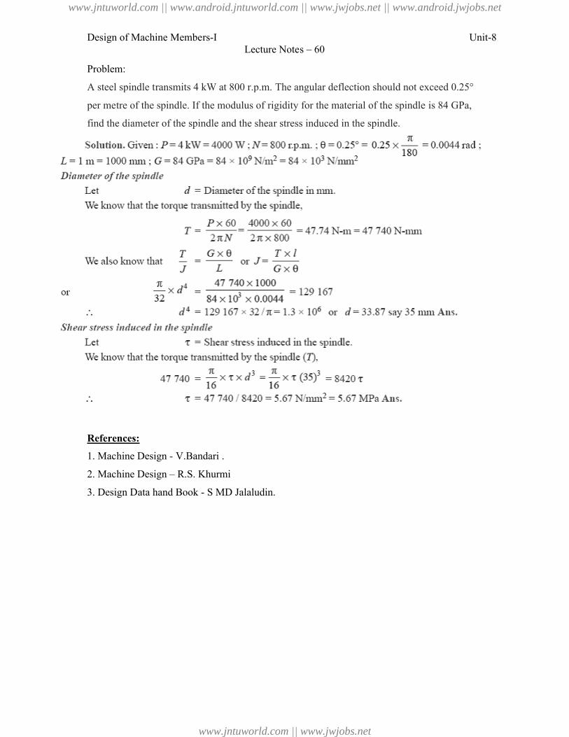
Design of Machine Members-I
Problem:
A steel spindle transmits 4 kW at 800 r.p.m. T
per metre of the spindle. If the modulus of rigidity for the material of the s
find the diameter of the spindle and the s
References:
1. Machine Design - V.Bandari .
2. Machine Design – R.S. Khurmi
3. Design Data hand Book - S MD Jalaludin
Lecture Notes – 60
le transmits 4 kW at 800 r.p.m. The angular deflection should not exceed 0.25°
pindle. If the modulus of rigidity for the material of the spindle is 84
r of the spindle and the shear stress induced in the spindle.
V.Bandari .
R.S. Khurmi
S MD Jalaludin.
Unit-8
exceed 0.25°
rigidity for the material of the spindle is 84 GPa,
www.jntuworld.com || www.android.jntuworld.com || www.jwjobs.net || www.android.jwjobs.net
www.jntuworld.com || www.jwjobs.net

Design of Machine Members-I Unit-8
Lecture Notes - 61
Use of internal and external circlips, Gaskets and seals
References:
1. Machine Design - V.Bandari .
2. Machine Design – R.S. Khurmi
3. Design Data hand Book - S MD Jalaludin.
www.jntuworld.com || www.android.jntuworld.com || www.jwjobs.net || www.android.jwjobs.net
www.jntuworld.com || www.jwjobs.net

Design of Machine Members-I Unit-8
Lecture Notes - 61
www.jntuworld.com || www.android.jntuworld.com || www.jwjobs.net || www.android.jwjobs.net
www.jntuworld.com || www.jwjobs.net
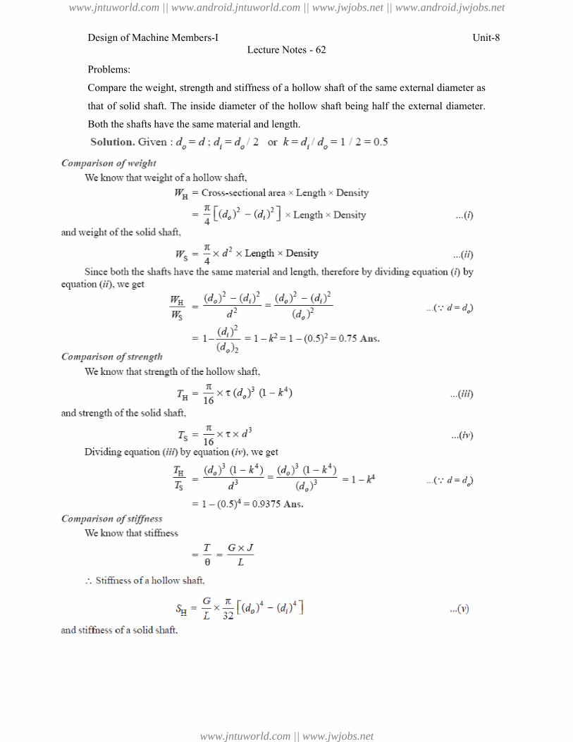
Design of Machine Members-I
Problems:
Compare the weight, strength and stif
that of solid shaft. The inside diameter
Both the shafts have the same material and le
Lecture Notes - 62
strength and stiffness of a hollow shaft of the same external
The inside diameter of the hollow shaft being half the external
hafts have the same material and length.
Unit-8
same external diameter as
external diameter.
www.jntuworld.com || www.android.jntuworld.com || www.jwjobs.net || www.android.jwjobs.net
www.jntuworld.com || www.jwjobs.net
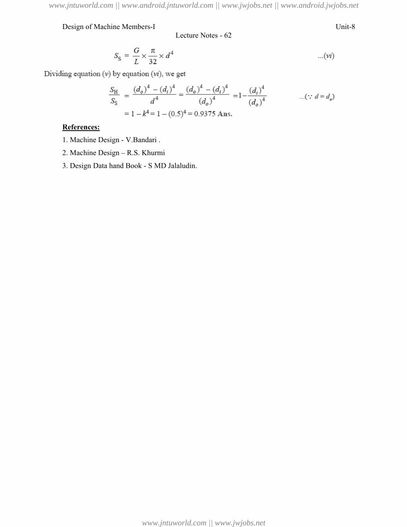
Design of Machine Members-I
References:
1. Machine Design - V.Bandari .
2. Machine Design – R.S. Khurmi
3. Design Data hand Book - S MD Jalaludin.
Lecture Notes - 62
V.Bandari .
R.S. Khurmi
S MD Jalaludin.
Unit-8
www.jntuworld.com || www.android.jntuworld.com || www.jwjobs.net || www.android.jwjobs.net
www.jntuworld.com || www.jwjobs.net
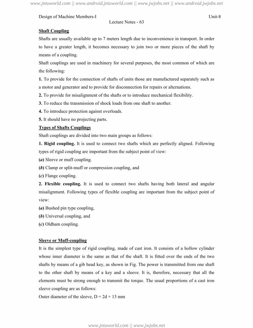
Design of Machine Members-I Unit-8Lecture Notes - 63
Shaft Coupling
Shafts are usually available up to 7 meters length due to inconvenience in transport. In order
to have a greater length, it becomes necessary to join two or more pieces of the shaft by
means of a coupling.
Shaft couplings are used in machinery for several purposes, the most common of which are
the following:
1. To provide for the connection of shafts of units those are manufactured separately such as
a motor and generator and to provide for disconnection for repairs or alternations.
2. To provide for misalignment of the shafts or to introduce mechanical flexibility.
3. To reduce the transmission of shock loads from one shaft to another.
4. To introduce protection against overloads.
5. It should have no projecting parts.
Types of Shafts Couplings
Shaft couplings are divided into two main groups as follows:
1. Rigid coupling. It is used to connect two shafts which are perfectly aligned. Following
types of rigid coupling are important from the subject point of view:
(a) Sleeve or muff coupling.
(b) Clamp or split-muff or compression coupling, and
(c) Flange coupling.
2. Flexible coupling. It is used to connect two shafts having both lateral and angular
misalignment. Following types of flexible coupling are important from the subject point of
view:
(a) Bushed pin type coupling,
(b) Universal coupling, and
(c) Oldham coupling.
Sleeve or Muff-coupling
It is the simplest type of rigid coupling, made of cast iron. It consists of a hollow cylinder
whose inner diameter is the same as that of the shaft. It is fitted over the ends of the two
shafts by means of a gib head key, as shown in Fig. The power is transmitted from one shaft
to the other shaft by means of a key and a sleeve. It is, therefore, necessary that all the
elements must be strong enough to transmit the torque. The usual proportions of a cast iron
sleeve coupling are as follows:
Outer diameter of the sleeve, D = 2d + 13 mm
www.jntuworld.com || www.android.jntuworld.com || www.jwjobs.net || www.android.jwjobs.net
www.jntuworld.com || www.jwjobs.net
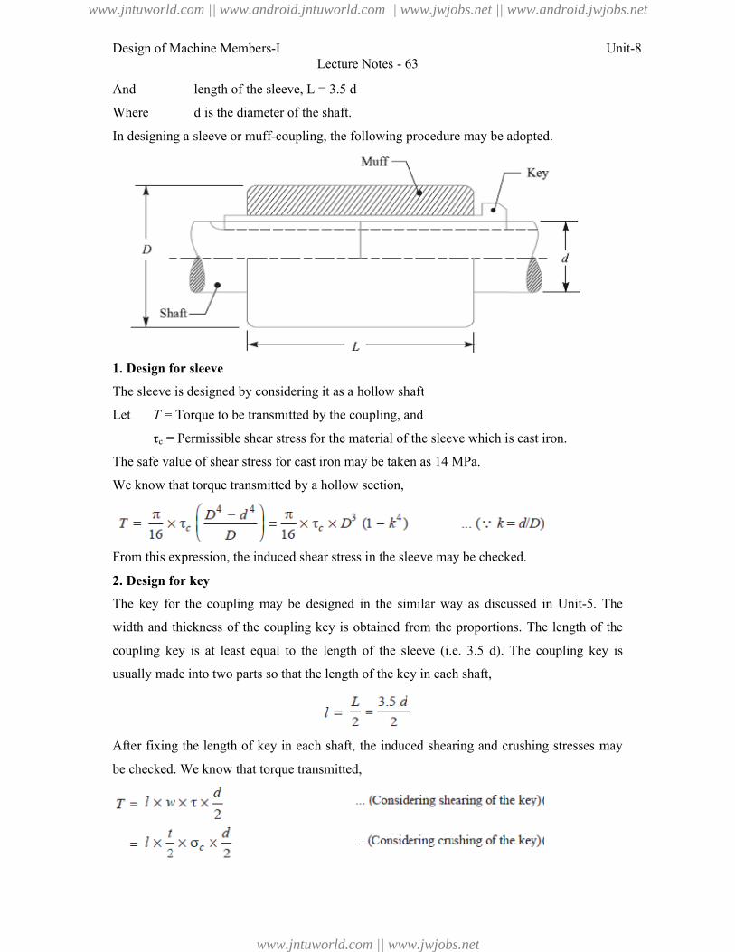
Design of Machine Members-I
And length of the sleeve,
Where d is the diameter of the shaft.
In designing a sleeve or muff-coupli
1. Design for sleeve
The sleeve is designed by considering it as a hollow shaft
Let T = Torque to be transmitted by the coupling, and
τc = Permissible shear stress for the material of the sleeve which is cast
The safe value of shear stress for cast iron may be taken as 14 MPa.
We know that torque transmitted by a hollow section,
From this expression, the induced shear stress in the sleeve may be checked
2. Design for key
The key for the coupling may be
width and thickness of the coupling key is obtained from the proportions.
coupling key is at least equal to the length of the sleeve (
usually made into two parts so that the length of the key in each shaft,
After fixing the length of key in each shaft, the induced shearing and crushing stresses may
be checked. We know that torque transmitted,
Lecture Notes - 63
length of the sleeve, L = 3.5 d
is the diameter of the shaft.
coupling, the following procedure may be adopted.
The sleeve is designed by considering it as a hollow shaft
= Torque to be transmitted by the coupling, and
= Permissible shear stress for the material of the sleeve which is cast iron.
The safe value of shear stress for cast iron may be taken as 14 MPa.
We know that torque transmitted by a hollow section,
From this expression, the induced shear stress in the sleeve may be checked.
The key for the coupling may be designed in the similar way as discussed in
width and thickness of the coupling key is obtained from the proportions. The length of the
least equal to the length of the sleeve (i.e. 3.5 d). The coupling key is
nto two parts so that the length of the key in each shaft,
After fixing the length of key in each shaft, the induced shearing and crushing stresses may
checked. We know that torque transmitted,
Unit-8
ng, the following procedure may be adopted.
iron.
designed in the similar way as discussed in Unit-5. The
The length of the
coupling key is
After fixing the length of key in each shaft, the induced shearing and crushing stresses may
www.jntuworld.com || www.android.jntuworld.com || www.jwjobs.net || www.android.jwjobs.net
www.jntuworld.com || www.jwjobs.net
Design of Machine Members-I Unit-8Lecture Notes - 63
Note: The depth of the keyway in each of the shafts to be connected should be exactly the
same and the diameters should also be same. If these conditions are not satisfied, then the key
will be bedded on one shaft while in the other it will be loose. In order to prevent this, the key
is made in two parts which may be driven from the same end for each shaft or they may be
driven from opposite ends.
References:
1. Machine Design - V.Bandari .
2. Machine Design – R.S. Khurmi
3. Design Data hand Book - S MD Jalaludin.
www.jntuworld.com || www.android.jntuworld.com || www.jwjobs.net || www.android.jwjobs.net
www.jntuworld.com || www.jwjobs.net
Design of Machine Members-I
Problem: Design and make a neat dimensioned sketch of a muff coupling which is used to
connect two steel shafts transmitting 40 kW at 350 r.p.m. The material for the shafts and key
is plain carbon steel for which allowable shear and crushing stresses may
and 80 MPa respectively. The material for the muff is cast iron for which the allowable shear
stress may be assumed as 15 MPa.
Solution.
Given: P = 40 kW = 40 × 103 W;
80 N/mm2; σc = 15 MPa = 15 N/mm
2. Design for sleeve
We know that outer diameter of the muff,
D = 2d + 13 mm = 2 × 55 + 13 = 123 say 125 mm
and length of the muff,
L = 3.5
Let us now check the induced shear stress in the
the muff which is made of cast iron. Since the muff is considered to be a hollow shaft,
therefore the torque transmitted (
Since the induced shear stress in the muff (cast iron) is less than the permissible
of 15 N/mm2, therefore the design of muff is safe.
3. Design for key
From Design data Book, we find that for a shaft of 55 mm diameter,
Lecture Notes - 64
Design and make a neat dimensioned sketch of a muff coupling which is used to
connect two steel shafts transmitting 40 kW at 350 r.p.m. The material for the shafts and key
carbon steel for which allowable shear and crushing stresses may be taken as 40 MPa
respectively. The material for the muff is cast iron for which the allowable shear
assumed as 15 MPa.
W; N = 350 r.p.m.; τs = 40 MPa = 40 N/mm2; σcs
= 15 MPa = 15 N/mm2.
We know that outer diameter of the muff,
+ 13 mm = 2 × 55 + 13 = 123 say 125 mm Ans.
= 3.5 d = 3.5 × 55 = 192.5 say 195 mm Ans.
Let us now check the induced shear stress in the muff. Let τc be the induced shear stress in
muff which is made of cast iron. Since the muff is considered to be a hollow shaft,
transmitted (T),
Since the induced shear stress in the muff (cast iron) is less than the permissible
15 N/mm2, therefore the design of muff is safe.
, we find that for a shaft of 55 mm diameter,
Width of key, w = 18 mm Ans.
Unit-8
Design and make a neat dimensioned sketch of a muff coupling which is used to
connect two steel shafts transmitting 40 kW at 350 r.p.m. The material for the shafts and key
be taken as 40 MPa
respectively. The material for the muff is cast iron for which the allowable shear
cs = 80 MPa =
be the induced shear stress in
muff which is made of cast iron. Since the muff is considered to be a hollow shaft,
Since the induced shear stress in the muff (cast iron) is less than the permissible shear stress
www.jntuworld.com || www.android.jntuworld.com || www.jwjobs.net || www.android.jwjobs.net
www.jntuworld.com || www.jwjobs.net
Design of Machine Members-I Unit-8Lecture Notes - 64
Since the crushing stress for the key material is twice the shearing stress, therefore a square
key may be used.
Then, Thickness of key, t = w = 18 mm Ans.
We know that length of key in each shaft,
l = L / 2 = 195 / 2 = 97.5 mm Ans.
Let us now check the induced shear and crushing stresses in the key. First of all, let us
consider shearing of the key. We know that torque transmitted (T),
Now considering crushing of the key. We know that torque transmitted (T),
Since the induced shear and crushing stresses are less than the permissible stresses, therefore
the design of key is safe.
References:
1. Machine Design - V.Bandari .
2. Machine Design – R.S. Khurmi
3. Design Data hand Book - S MD Jalaludin.
www.jntuworld.com || www.android.jntuworld.com || www.jwjobs.net || www.android.jwjobs.net
www.jntuworld.com || www.jwjobs.net

Design of Machine Members-I Unit-8Lecture Notes - 64
www.jntuworld.com || www.android.jntuworld.com || www.jwjobs.net || www.android.jwjobs.net
www.jntuworld.com || www.jwjobs.net
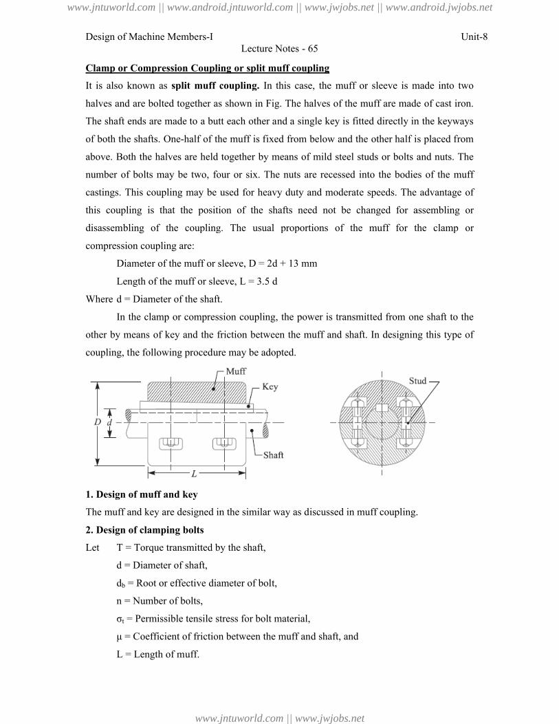
Design of Machine Members-I
Clamp or Compression Coupling
It is also known as split muff coupling
halves and are bolted together as shown in Fig
The shaft ends are made to a butt each other and a single key
of both the shafts. One-half of the muff is fixed from below and the
above. Both the halves are held together by means of mild steel studs or bolts
number of bolts may be two, four or six. The nuts are recessed into the bodies of the
castings. This coupling may be used for heavy duty and moderate speeds. The advantage of
this coupling is that the position of the shafts need not be ch
disassembling of the coupling. The usual proportions of the muff for the clamp o
compression coupling are:
Diameter of the muff or sleeve,
Length of the muff or sleeve,
Where d = Diameter of the shaft.
In the clamp or compression coupling, the power is transmitted from one shaft to the
other by means of key and the friction between the muff and shaft. In designing this type of
coupling, the following procedure may be adopted.
1. Design of muff and key
The muff and key are designed in the similar way as discussed in muff coupl
2. Design of clamping bolts
Let T = Torque transmitted by the shaft,
d = Diameter of shaft,
db = Root or effective diameter of bolt,
n = Number of bolts,
σt = Permissible tensile stress for bolt material,
μ = Coefficient of friction between the muff and shaft, and
L = Length of muff.
Lecture Notes - 65
Clamp or Compression Coupling or split muff coupling
split muff coupling. In this case, the muff or sleeve is made into two
ted together as shown in Fig. The halves of the muff are made of cast iron.
butt each other and a single key is fitted directly in the keyways
half of the muff is fixed from below and the other half is placed from
held together by means of mild steel studs or bolts a
number of bolts may be two, four or six. The nuts are recessed into the bodies of the
castings. This coupling may be used for heavy duty and moderate speeds. The advantage of
coupling is that the position of the shafts need not be changed for assembling or
coupling. The usual proportions of the muff for the clamp o
Diameter of the muff or sleeve, D = 2d + 13 mm
Length of the muff or sleeve, L = 3.5 d
= Diameter of the shaft.
the clamp or compression coupling, the power is transmitted from one shaft to the
means of key and the friction between the muff and shaft. In designing this type of
following procedure may be adopted.
muff and key are designed in the similar way as discussed in muff coupling.
= Torque transmitted by the shaft,
= Root or effective diameter of bolt,
stress for bolt material,
μ = Coefficient of friction between the muff and shaft, and
Unit-8
this case, the muff or sleeve is made into two
halves of the muff are made of cast iron.
is fitted directly in the keyways
other half is placed from
and nuts. The
number of bolts may be two, four or six. The nuts are recessed into the bodies of the muff
castings. This coupling may be used for heavy duty and moderate speeds. The advantage of
anged for assembling or
coupling. The usual proportions of the muff for the clamp or
the clamp or compression coupling, the power is transmitted from one shaft to the
means of key and the friction between the muff and shaft. In designing this type of
.
www.jntuworld.com || www.android.jntuworld.com || www.jwjobs.net || www.android.jwjobs.net
www.jntuworld.com || www.jwjobs.net
Design of Machine Members-I Unit-8Lecture Notes - 65
We know that the force exerted by each bolt
Then, Force exerted by the bolts on each side of the shaft
Let p be the pressure on the shaft and the muff surface due to the force, then for uniform
pressure distribution over the surface,
Then, Frictional force between each shaft and muff,
And the torque that can be transmitted by the coupling,
From this relation, the root diameter of the bolt (db) may be evaluated.
Flange Coupling
A flange coupling usually applies to a coupling having two separate cast iron flanges. Each
flange is mounted on the shaft end and keyed to it. The faces are turned up at right angle to
the axis of the shaft. One of the flanges has a projected portion and the other flange has a
corresponding recess. This helps to bring the shafts into line and to maintain alignment. The
two flanges are coupled together by means of bolts and nuts. The flange coupling is adapted
to heavy loads and hence it is used on large shafting.
The flange couplings are of the following three types:
www.jntuworld.com || www.android.jntuworld.com || www.jwjobs.net || www.android.jwjobs.net
www.jntuworld.com || www.jwjobs.net
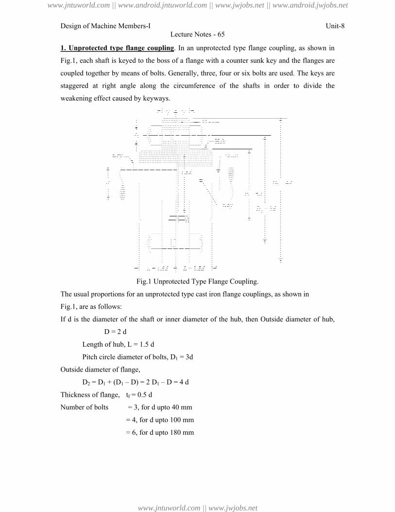
Design of Machine Members-I
1. Unprotected type flange coupling
Fig.1, each shaft is keyed to the boss
coupled together by means of bolts. Generally, three,
staggered at right angle along the
weakening effect caused by keyways.
Fig.1 Unprotected Type Flange Coupling.
The usual proportions for an unprotected type cast iron flange couplings, as shown in
Fig.1, are as follows:
If d is the diameter of the shaft or inner diameter of the hub, then
D = 2 d
Length of hub, L = 1.5 d
Pitch circle diameter of bolts,
Outside diameter of flange,
D2 = D1 + (D1 – D) = 2 D
Thickness of flange, tf = 0.5 d
Number of bolts = 3, for d
= 4, for d upto 100 mm
= 6, for d upto 180 mm
Lecture Notes - 65
Unprotected type flange coupling. In an unprotected type flange coupling, as shown in
, each shaft is keyed to the boss of a flange with a counter sunk key and the flanges are
by means of bolts. Generally, three, four or six bolts are used. The keys
staggered at right angle along the circumference of the shafts in order to divide the
by keyways.
Unprotected Type Flange Coupling.
The usual proportions for an unprotected type cast iron flange couplings, as shown in
is the diameter of the shaft or inner diameter of the hub, then Outside diameter of hub,
Pitch circle diameter of bolts, D1 = 3d
D1 – D = 4 d
d upto 40 mm
upto 100 mm
upto 180 mm
Unit-8
flange coupling, as shown in
and the flanges are
four or six bolts are used. The keys are
to divide the
The usual proportions for an unprotected type cast iron flange couplings, as shown in
Outside diameter of hub,
www.jntuworld.com || www.android.jntuworld.com || www.jwjobs.net || www.android.jwjobs.net
www.jntuworld.com || www.jwjobs.net
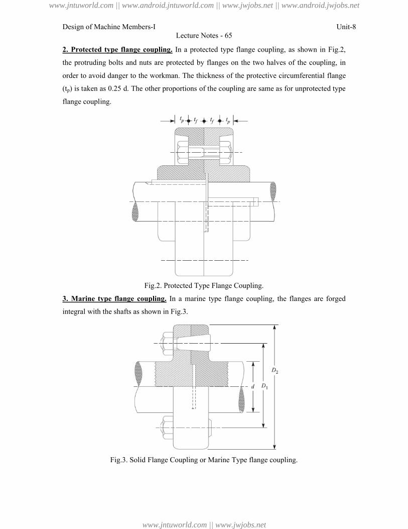
Design of Machine Members-I
2. Protected type flange coupling
the protruding bolts and nuts are protected by flanges on the two halves of the coupling, in
order to avoid danger to the workman.
(tp) is taken as 0.25 d. The other proportions
flange coupling.
Fig.2. Protected Type Flange Coupling.
3. Marine type flange coupling
integral with the shafts as shown in Fig.3
Fig.3. Solid Flange Coupling or Marine Type flange coupling.
Lecture Notes - 65
flange coupling. In a protected type flange coupling, as shown in Fig.2
the protruding bolts and nuts are protected by flanges on the two halves of the coupling, in
avoid danger to the workman. The thickness of the protective circumferential flan
. The other proportions of the coupling are same as for unprotected type
Fig.2. Protected Type Flange Coupling.
Marine type flange coupling. In a marine type flange coupling, the flanges are forged
ith the shafts as shown in Fig.3.
Fig.3. Solid Flange Coupling or Marine Type flange coupling.
Unit-8
ange coupling, as shown in Fig.2,
the protruding bolts and nuts are protected by flanges on the two halves of the coupling, in
The thickness of the protective circumferential flange
of the coupling are same as for unprotected type
In a marine type flange coupling, the flanges are forged
www.jntuworld.com || www.android.jntuworld.com || www.jwjobs.net || www.android.jwjobs.net
www.jntuworld.com || www.jwjobs.net
Design of Machine Members-I Unit-8Lecture Notes - 65
The flanges are held together by means of tapered headless bolts, numbering from four to
twelve depending upon the diameter of shaft. The other proportions for the marine type
flange coupling are taken as follows:
Thickness of flange = d / 3
Taper of bolt = 1 in 20 to 1 in 40
Pitch circle diameter of bolts, D1 = 1.6 d
Outside diameter of flange, D2 = 2.2 d
Design of Flange Coupling
Consider a flange coupling as shown in Fig.1 and Fig.2.
Let d = Diameter of shaft or inner diameter of hub,
D = Outer diameter of hub,
D1 = Nominal or outside diameter of bolt,
D1 = Diameter of bolt circle,
n = Number of bolts,
tf = Thickness of flange,
τs, τb and τk = Allowable shear stress for shaft, bolt and key material respectively
τc = Allowable shear stress for the flange material i.e. cast iron,
σcb, and σck = Allowable crushing stress for bolt and key material respectively.
The flange coupling is designed as discussed below:
1. Design for hub
The hub is designed by considering it as a hollow shaft, transmitting the same torque (T) as
that of a solid shaft.
The outer diameter of hub is usually taken as twice the diameter of shaft. Therefore from the
above relation, the induced shearing stress in the hub may be checked.
The length of hub (L) is taken as 1.5 d.
2. Design for key
The key is designed with usual proportions and then checked for shearing and crushing
stresses. The material of key is usually the same as that of shaft. The length of key is taken
equal to the length of hub.
3. Design for flange
www.jntuworld.com || www.android.jntuworld.com || www.jwjobs.net || www.android.jwjobs.net
www.jntuworld.com || www.jwjobs.net
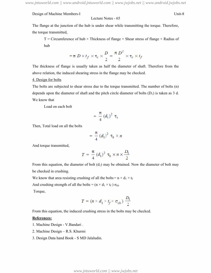
Design of Machine Members-I Unit-8Lecture Notes - 65
The flange at the junction of the hub is under shear while transmitting the torque. Therefore,
the torque transmitted,
T = Circumference of hub × Thickness of flange × Shear stress of flange × Radius of
hub
The thickness of flange is usually taken as half the diameter of shaft. Therefore from the
above relation, the induced shearing stress in the flange may be checked.
4. Design for bolts
The bolts are subjected to shear stress due to the torque transmitted. The number of bolts (n)
depends upon the diameter of shaft and the pitch circle diameter of bolts (D1) is taken as 3 d.
We know that
Load on each bolt
Then, Total load on all the bolts
And torque transmitted,
From this equation, the diameter of bolt (d1) may be obtained. Now the diameter of bolt may
be checked in crushing.
We know that area resisting crushing of all the bolts = n × d1 × tf
And crushing strength of all the bolts = (n × d1 × tf ) σcb
Torque,
From this equation, the induced crushing stress in the bolts may be checked.
References:
1. Machine Design - V.Bandari .
2. Machine Design – R.S. Khurmi
3. Design Data hand Book - S MD Jalaludin.
www.jntuworld.com || www.android.jntuworld.com || www.jwjobs.net || www.android.jwjobs.net
www.jntuworld.com || www.jwjobs.net
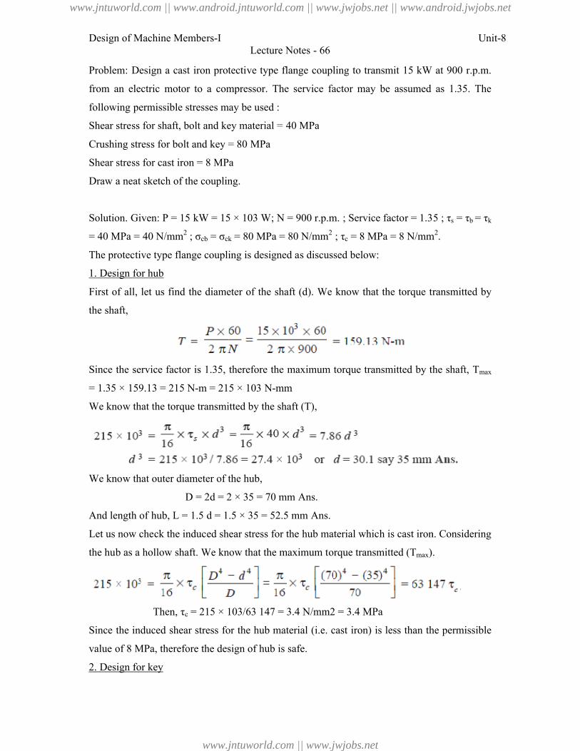
Design of Machine Members-I
Problem: Design a cast iron protective type flange coupling to transmit 15 kW at 900
from an electric motor to a compressor. The service factor may be assumed as 1.35. The
following permissible stresses may be used :
Shear stress for shaft, bolt and key material = 40 MPa
Crushing stress for bolt and key = 80 MPa
Shear stress for cast iron = 8 MPa
Draw a neat sketch of the coupling.
Solution. Given: P = 15 kW = 15 × 103 W;
= 40 MPa = 40 N/mm2 ; σcb = σck
The protective type flange coupling is designed as discussed below:
1. Design for hub
First of all, let us find the diameter of the shaft (
the shaft,
Since the service factor is 1.35, therefore the maximum torque transmitted by the shaft,
= 1.35 × 159.13 = 215 N-m = 215 × 103 N
We know that the torque transmitted by the shaft (
We know that outer diameter of the hub,
D = 2d = 2 × 35 = 70 mm
And length of hub, L = 1.5 d = 1.5 × 35 = 52.5 mm
Let us now check the induced shear stress for the hub material which is cast iron. Considering
the hub as a hollow shaft. We know that the maximum torque transmitted (
Then, τc = 215 × 103/63 1
Since the induced shear stress for the hub material (
value of 8 MPa, therefore the design of hub is safe.
2. Design for key
Lecture Notes - 66
Problem: Design a cast iron protective type flange coupling to transmit 15 kW at 900
from an electric motor to a compressor. The service factor may be assumed as 1.35. The
following permissible stresses may be used :
and key material = 40 MPa
Crushing stress for bolt and key = 80 MPa
Shear stress for cast iron = 8 MPa
Draw a neat sketch of the coupling.
= 15 kW = 15 × 103 W; N = 900 r.p.m. ; Service factor = 1.35 ; τ
ck = 80 MPa = 80 N/mm2 ; τc = 8 MPa = 8 N/mm
The protective type flange coupling is designed as discussed below:
First of all, let us find the diameter of the shaft (d). We know that the torque transmitted by
the service factor is 1.35, therefore the maximum torque transmitted by the shaft,
m = 215 × 103 N-mm
We know that the torque transmitted by the shaft (T),
We know that outer diameter of the hub,
= 2 × 35 = 70 mm Ans.
= 1.5 × 35 = 52.5 mm Ans.
Let us now check the induced shear stress for the hub material which is cast iron. Considering
the hub as a hollow shaft. We know that the maximum torque transmitted (Tmax).
= 215 × 103/63 147 = 3.4 N/mm2 = 3.4 MPa
Since the induced shear stress for the hub material (i.e. cast iron) is less than the permissible
value of 8 MPa, therefore the design of hub is safe.
Unit-8
Problem: Design a cast iron protective type flange coupling to transmit 15 kW at 900 r.p.m.
from an electric motor to a compressor. The service factor may be assumed as 1.35. The
= 900 r.p.m. ; Service factor = 1.35 ; τs = τb = τk
= 8 MPa = 8 N/mm2.
). We know that the torque transmitted by
the service factor is 1.35, therefore the maximum torque transmitted by the shaft, Tmax
Let us now check the induced shear stress for the hub material which is cast iron. Considering
).
. cast iron) is less than the permissible
www.jntuworld.com || www.android.jntuworld.com || www.jwjobs.net || www.android.jwjobs.net
www.jntuworld.com || www.jwjobs.net
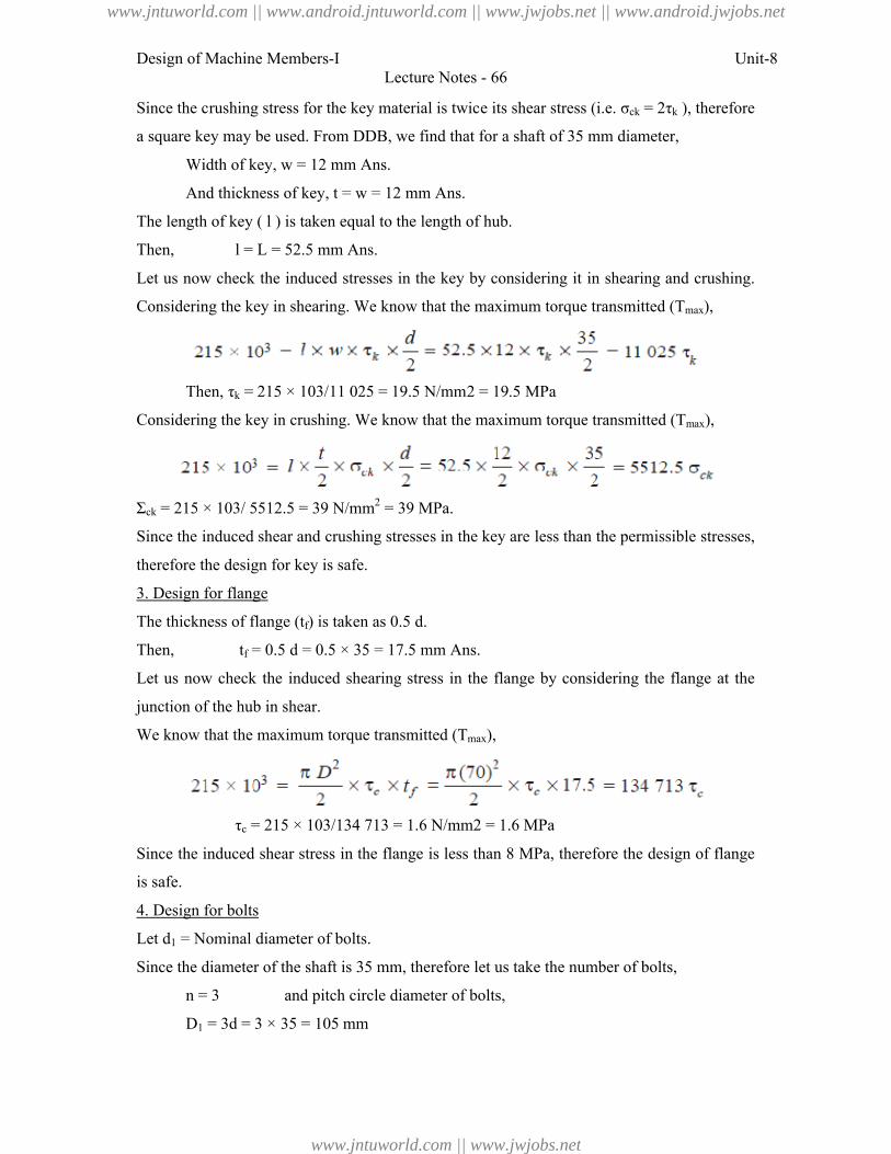
Design of Machine Members-I Unit-8Lecture Notes - 66
Since the crushing stress for the key material is twice its shear stress (i.e. σck = 2τk ), therefore
a square key may be used. From DDB, we find that for a shaft of 35 mm diameter,
Width of key, w = 12 mm Ans.
And thickness of key, t = w = 12 mm Ans.
The length of key ( l ) is taken equal to the length of hub.
Then, l = L = 52.5 mm Ans.
Let us now check the induced stresses in the key by considering it in shearing and crushing.
Considering the key in shearing. We know that the maximum torque transmitted (Tmax),
Then, τk = 215 × 103/11 025 = 19.5 N/mm2 = 19.5 MPa
Considering the key in crushing. We know that the maximum torque transmitted (Tmax),
Σck = 215 × 103/ 5512.5 = 39 N/mm2 = 39 MPa.
Since the induced shear and crushing stresses in the key are less than the permissible stresses,
therefore the design for key is safe.
3. Design for flange
The thickness of flange (tf) is taken as 0.5 d.
Then, tf = 0.5 d = 0.5 × 35 = 17.5 mm Ans.
Let us now check the induced shearing stress in the flange by considering the flange at the
junction of the hub in shear.
We know that the maximum torque transmitted (Tmax),
τc = 215 × 103/134 713 = 1.6 N/mm2 = 1.6 MPa
Since the induced shear stress in the flange is less than 8 MPa, therefore the design of flange
is safe.
4. Design for bolts
Let d1 = Nominal diameter of bolts.
Since the diameter of the shaft is 35 mm, therefore let us take the number of bolts,
n = 3 and pitch circle diameter of bolts,
D1 = 3d = 3 × 35 = 105 mm
www.jntuworld.com || www.android.jntuworld.com || www.jwjobs.net || www.android.jwjobs.net
www.jntuworld.com || www.jwjobs.net
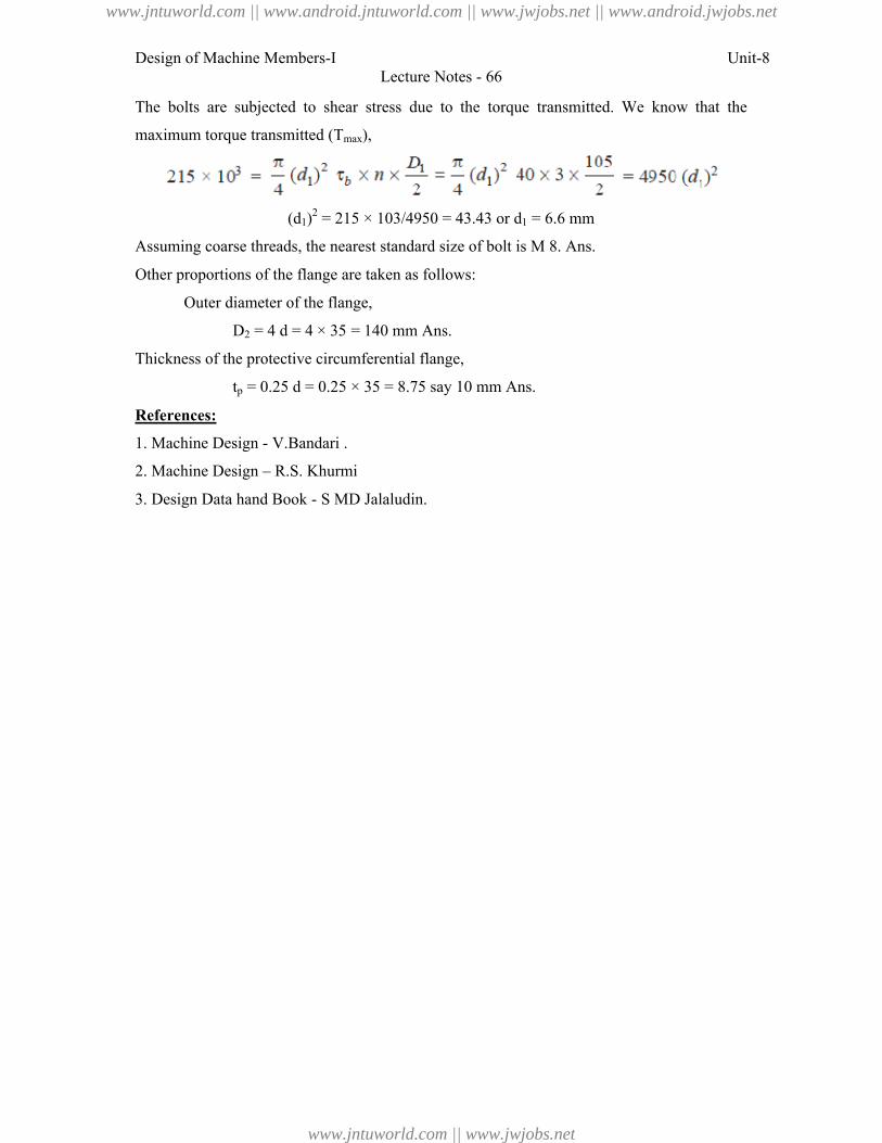
Design of Machine Members-I Unit-8Lecture Notes - 66
The bolts are subjected to shear stress due to the torque transmitted. We know that the
maximum torque transmitted (Tmax),
(d1)2 = 215 × 103/4950 = 43.43 or d1 = 6.6 mm
Assuming coarse threads, the nearest standard size of bolt is M 8. Ans.
Other proportions of the flange are taken as follows:
Outer diameter of the flange,
D2 = 4 d = 4 × 35 = 140 mm Ans.
Thickness of the protective circumferential flange,
tp = 0.25 d = 0.25 × 35 = 8.75 say 10 mm Ans.
References:
1. Machine Design - V.Bandari .
2. Machine Design – R.S. Khurmi
3. Design Data hand Book - S MD Jalaludin.
www.jntuworld.com || www.android.jntuworld.com || www.jwjobs.net || www.android.jwjobs.net
www.jntuworld.com || www.jwjobs.net
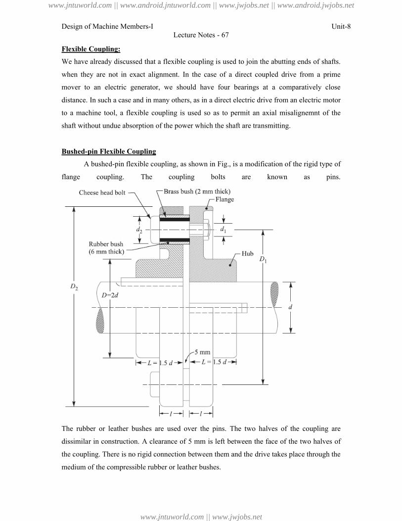
Design of Machine Members-I
Flexible Coupling:
We have already discussed that a flexible coupling is used to join the abutting ends of shafts.
when they are not in exact alignment. In the case of a direct coupled drive from a prime
mover to an electric generator, we should have four
distance. In such a case and in many others, as in a direct electric drive from an electric motor
to a machine tool, a flexible coupling is used so as to permit an axial misalignemnt of the
shaft without undue absorption of the
Bushed-pin Flexible Coupling
A bushed-pin flexible coupling, as shown in Fig.
flange coupling. The coupling bolts are known as pins.
The rubber or leather bushes are
dissimilar in construction. A clearance of 5 mm is left
the coupling. There is no rigid connection between them and the
medium of the compressible rubber or leather bushes.
Lecture Notes - 67
We have already discussed that a flexible coupling is used to join the abutting ends of shafts.
when they are not in exact alignment. In the case of a direct coupled drive from a prime
electric generator, we should have four bearings at a comparatively close
in many others, as in a direct electric drive from an electric motor
coupling is used so as to permit an axial misalignemnt of the
of the power which the shaft are transmitting.
ible coupling, as shown in Fig., is a modification of the rigid type of
flange coupling. The coupling bolts are known as pins.
The rubber or leather bushes are used over the pins. The two halves of the coupling are
dissimilar in construction. A clearance of 5 mm is left between the face of the two halves of
the coupling. There is no rigid connection between them and the drive takes place through the
compressible rubber or leather bushes.
Unit-8
We have already discussed that a flexible coupling is used to join the abutting ends of shafts.
when they are not in exact alignment. In the case of a direct coupled drive from a prime
bearings at a comparatively close
in many others, as in a direct electric drive from an electric motor
coupling is used so as to permit an axial misalignemnt of the
, is a modification of the rigid type of
flange coupling. The coupling bolts are known as pins.
pins. The two halves of the coupling are
between the face of the two halves of
drive takes place through the
www.jntuworld.com || www.android.jntuworld.com || www.jwjobs.net || www.android.jwjobs.net
www.jntuworld.com || www.jwjobs.net
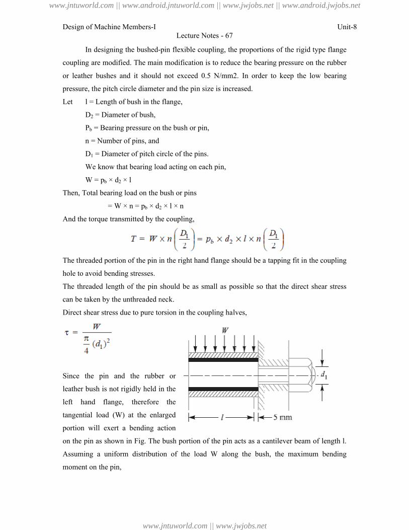
Design of Machine Members-I
In designing the bushed-pin flexible coupling, the proportions of the rigid type flange
coupling are modified. The main modification is to reduce the bearing pressure on the rubber
or leather bushes and it should not
pressure, the pitch circle diameter and the pin size is increased.
Let l = Length of bush in the flange,
D2 = Diameter of bush,
Pb = Bearing pressure on the bush or pin,
n = Number of pins, and
D1 = Diameter of pitch circle of the pins.
We know that bearing load acting on each pin,
W = pb × d2 × l
Then, Total bearing load on the bush or pins
= W × n = pb × d2
And the torque transmitted by the coupling,
The threaded portion of the pin in the
hole to avoid bending stresses.
The threaded length of the pin should be as small as possible so that the direct shear stress
can be taken by the unthreaded neck.
Direct shear stress due to pure torsion in the coupling halves,
Since the pin and the rubber or
leather bush is not rigidly held in the
left hand flange, therefore the
tangential load (W) at the enlarged
portion will exert a bending action
on the pin as shown in Fig. The bush porti
Assuming a uniform distribution of the load
moment on the pin,
Lecture Notes - 67
pin flexible coupling, the proportions of the rigid type flange
are modified. The main modification is to reduce the bearing pressure on the rubber
and it should not exceed 0.5 N/mm2. In order to keep the low bearing
diameter and the pin size is increased.
= Length of bush in the flange,
= Bearing pressure on the bush or pin,
eter of pitch circle of the pins.
We know that bearing load acting on each pin,
Total bearing load on the bush or pins
2 × l × n
And the torque transmitted by the coupling,
The threaded portion of the pin in the right hand flange should be a tapping fit in the coupling
The threaded length of the pin should be as small as possible so that the direct shear stress
be taken by the unthreaded neck.
torsion in the coupling halves,
Since the pin and the rubber or
rigidly held in the
left hand flange, therefore the
) at the enlarged
action
. The bush portion of the pin acts as a cantilever beam of length
a uniform distribution of the load W along the bush, the maximum bending
Unit-8
pin flexible coupling, the proportions of the rigid type flange
are modified. The main modification is to reduce the bearing pressure on the rubber
exceed 0.5 N/mm2. In order to keep the low bearing
right hand flange should be a tapping fit in the coupling
The threaded length of the pin should be as small as possible so that the direct shear stress
of the pin acts as a cantilever beam of length l.
maximum bending
www.jntuworld.com || www.android.jntuworld.com || www.jwjobs.net || www.android.jwjobs.net
www.jntuworld.com || www.jwjobs.net
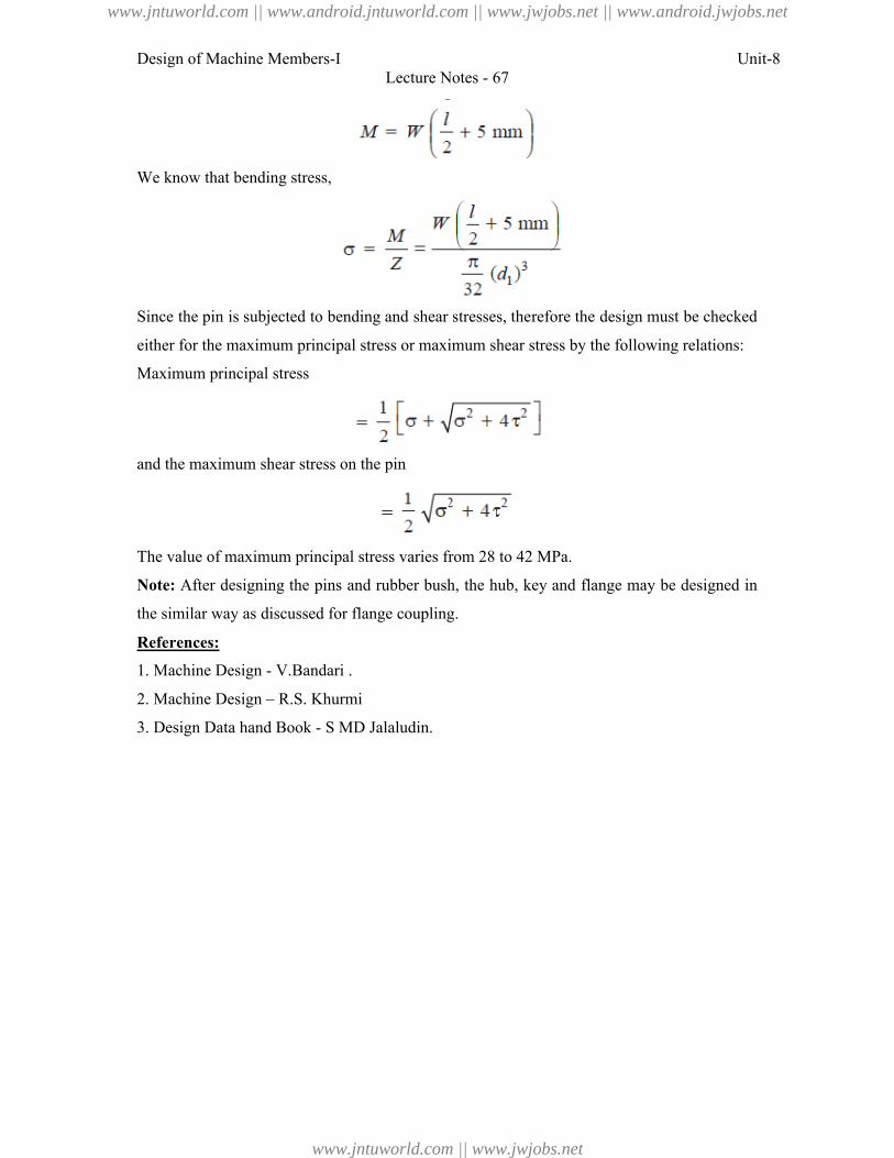
Design of Machine Members-I Unit-8Lecture Notes - 67
We know that bending stress,
Since the pin is subjected to bending and shear stresses, therefore the design must be checked
either for the maximum principal stress or maximum shear stress by the following relations:
Maximum principal stress
and the maximum shear stress on the pin
The value of maximum principal stress varies from 28 to 42 MPa.
Note: After designing the pins and rubber bush, the hub, key and flange may be designed in
the similar way as discussed for flange coupling.
References:
1. Machine Design - V.Bandari .
2. Machine Design – R.S. Khurmi
3. Design Data hand Book - S MD Jalaludin.
www.jntuworld.com || www.android.jntuworld.com || www.jwjobs.net || www.android.jwjobs.net
www.jntuworld.com || www.jwjobs.net

Design of Machine Members-I Unit-8Lecture Notes - 67
www.jntuworld.com || www.android.jntuworld.com || www.jwjobs.net || www.android.jwjobs.net
www.jntuworld.com || www.jwjobs.net
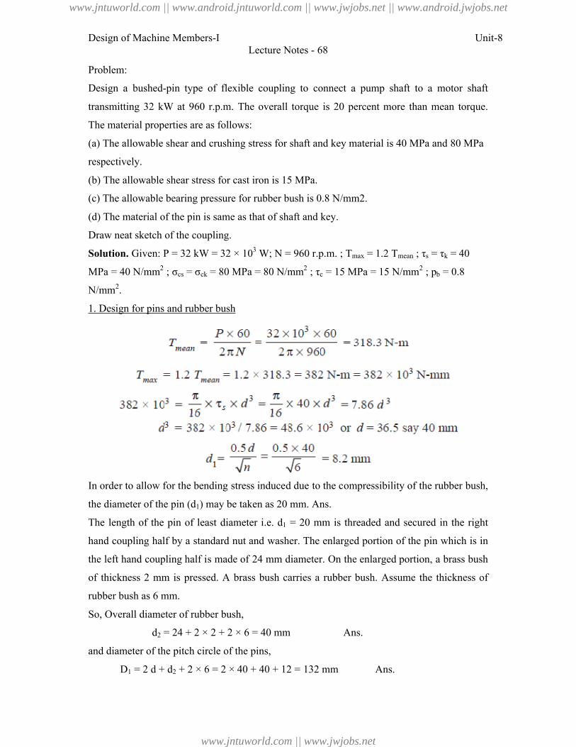
Design of Machine Members-I Unit-8Lecture Notes - 68
Problem:
Design a bushed-pin type of flexible coupling to connect a pump shaft to a motor shaft
transmitting 32 kW at 960 r.p.m. The overall torque is 20 percent more than mean torque.
The material properties are as follows:
(a) The allowable shear and crushing stress for shaft and key material is 40 MPa and 80 MPa
respectively.
(b) The allowable shear stress for cast iron is 15 MPa.
(c) The allowable bearing pressure for rubber bush is 0.8 N/mm2.
(d) The material of the pin is same as that of shaft and key.
Draw neat sketch of the coupling.
Solution. Given: P = 32 kW = 32 × 103 W; N = 960 r.p.m. ; Tmax = 1.2 Tmean ; τs = τk = 40
MPa = 40 N/mm2 ; σcs = σck = 80 MPa = 80 N/mm2 ; τc = 15 MPa = 15 N/mm2 ; pb = 0.8
N/mm2.
1. Design for pins and rubber bush
In order to allow for the bending stress induced due to the compressibility of the rubber bush,
the diameter of the pin (d1) may be taken as 20 mm. Ans.
The length of the pin of least diameter i.e. d1 = 20 mm is threaded and secured in the right
hand coupling half by a standard nut and washer. The enlarged portion of the pin which is in
the left hand coupling half is made of 24 mm diameter. On the enlarged portion, a brass bush
of thickness 2 mm is pressed. A brass bush carries a rubber bush. Assume the thickness of
rubber bush as 6 mm.
So, Overall diameter of rubber bush,
d2 = 24 + 2 × 2 + 2 × 6 = 40 mm Ans.
and diameter of the pitch circle of the pins,
D1 = 2 d + d2 + 2 × 6 = 2 × 40 + 40 + 12 = 132 mm Ans.
www.jntuworld.com || www.android.jntuworld.com || www.jwjobs.net || www.android.jwjobs.net
www.jntuworld.com || www.jwjobs.net
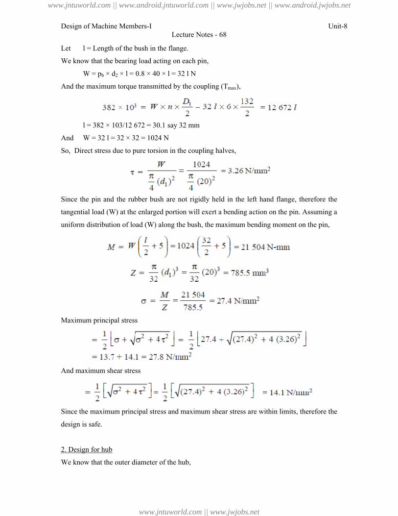
Design of Machine Members-I Unit-8Lecture Notes - 68
Let l = Length of the bush in the flange.
We know that the bearing load acting on each pin,
W = pb × d2 × l = 0.8 × 40 × l = 32 l N
And the maximum torque transmitted by the coupling (Tmax),
l = 382 × 103/12 672 = 30.1 say 32 mm
And W = 32 l = 32 × 32 = 1024 N
So, Direct stress due to pure torsion in the coupling halves,
Since the pin and the rubber bush are not rigidly held in the left hand flange, therefore the
tangential load (W) at the enlarged portion will exert a bending action on the pin. Assuming a
uniform distribution of load (W) along the bush, the maximum bending moment on the pin,
Maximum principal stress
And maximum shear stress
Since the maximum principal stress and maximum shear stress are within limits, therefore the
design is safe.
2. Design for hub
We know that the outer diameter of the hub,
www.jntuworld.com || www.android.jntuworld.com || www.jwjobs.net || www.android.jwjobs.net
www.jntuworld.com || www.jwjobs.net
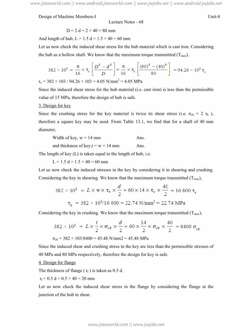
Design of Machine Members-I Unit-8Lecture Notes - 68
D = 2 d = 2 × 40 = 80 mm
And length of hub, L = 1.5 d = 1.5 × 40 = 60 mm
Let us now check the induced shear stress for the hub material which is cast iron. Considering
the hub as a hollow shaft. We know that the maximum torque transmitted (Tmax),
τc = 382 × 103 / 94.26 × 103 = 4.05 N/mm2 = 4.05 MPa
Since the induced shear stress for the hub material (i.e. cast iron) is less than the permissible
value of 15 MPa, therefore the design of hub is safe.
3. Design for key
Since the crushing stress for the key material is twice its shear stress (i.e. σck = 2 τk ),
therefore a square key may be used. From Table 13.1, we find that for a shaft of 40 mm
diameter,
Width of key, w = 14 mm Ans.
and thickness of key,t = w = 14 mm Ans.
The length of key (L) is taken equal to the length of hub, i.e.
L = 1.5 d = 1.5 × 40 = 60 mm
Let us now check the induced stresses in the key by considering it in shearing and crushing.
Considering the key in shearing. We know that the maximum torque transmitted (Tmax),
Considering the key in crushing. We know that the maximum torque transmitted (Tmax),
σck = 382 × 103/8400 = 45.48 N/mm2 = 45.48 MPa
Since the induced shear and crushing stress in the key are less than the permissible stresses of
40 MPa and 80 MPa respectively, therefore the design for key is safe.
4. Design for flange
The thickness of flange ( tf ) is taken as 0.5 d.
tf = 0.5 d = 0.5 × 40 = 20 mm
Let us now check the induced shear stress in the flange by considering the flange at the
junction of the hub in shear.
www.jntuworld.com || www.android.jntuworld.com || www.jwjobs.net || www.android.jwjobs.net
www.jntuworld.com || www.jwjobs.net
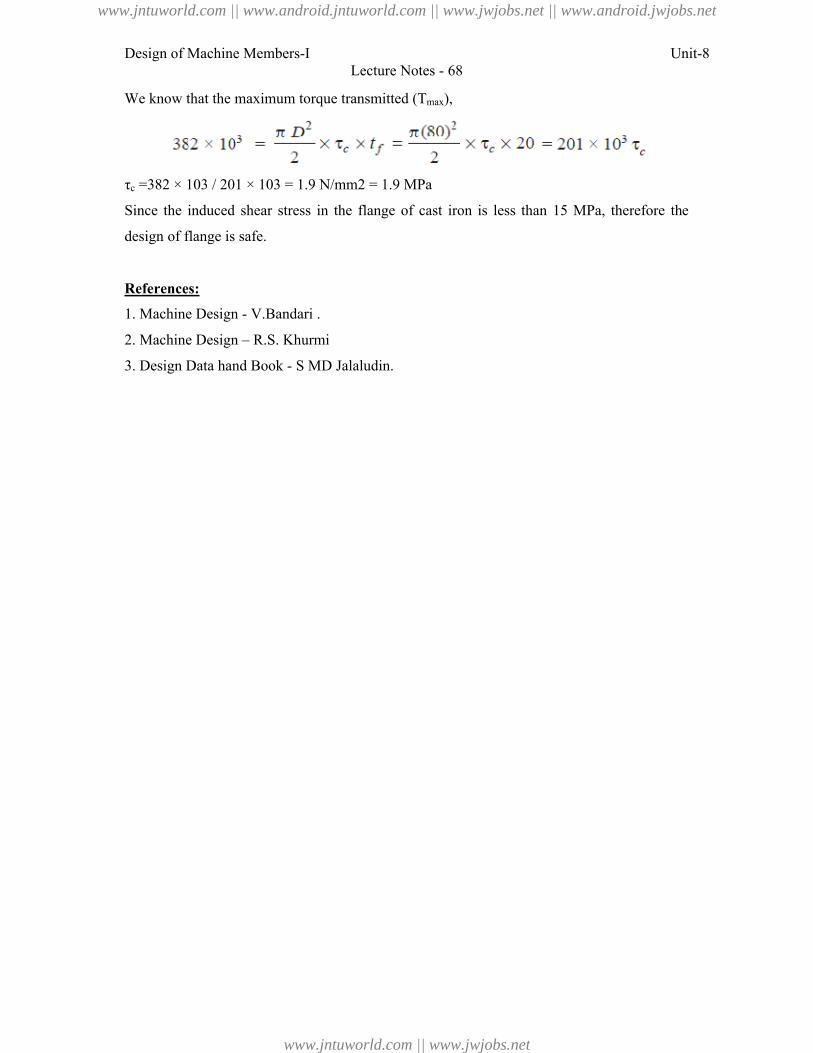
Design of Machine Members-I Unit-8Lecture Notes - 68
We know that the maximum torque transmitted (Tmax),
τc =382 × 103 / 201 × 103 = 1.9 N/mm2 = 1.9 MPa
Since the induced shear stress in the flange of cast iron is less than 15 MPa, therefore the
design of flange is safe.
References:
1. Machine Design - V.Bandari .
2. Machine Design – R.S. Khurmi
3. Design Data hand Book - S MD Jalaludin.
www.jntuworld.com || www.android.jntuworld.com || www.jwjobs.net || www.android.jwjobs.net
www.jntuworld.com || www.jwjobs.net
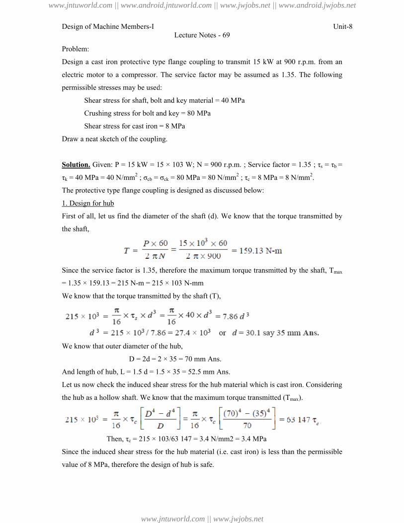
Design of Machine Members-I
Problem:
Design a cast iron protective type flange coupling to transmit 15 kW at 900
electric motor to a compressor. The service factor may be assumed as 1.35. The
permissible stresses may be used:
Shear stress for shaft, bolt
Crushing stress for bolt and key = 80 MPa
Shear stress for cast iron = 8 MPa
Draw a neat sketch of the coupling.
Solution. Given: P = 15 kW = 15 × 103 W;
τk = 40 MPa = 40 N/mm2 ; σcb = σ
The protective type flange coupling is designed as discussed below:
1. Design for hub
First of all, let us find the diameter of the shaft (
the shaft,
Since the service factor is 1.35, therefore the maximum torque transmitted by the shaft,
= 1.35 × 159.13 = 215 N-m = 215 × 103 N
We know that the torque transmitted by the shaft (
We know that outer diameter of the hub,
D = 2d = 2 × 35 = 70 mm
And length of hub, L = 1.5 d = 1.5 × 35 = 52.5 mm
Let us now check the induced shear stress for the hub material which is cast iron. Considering
the hub as a hollow shaft. We know that the maximum torque transmitted (
Then, τc = 215 × 103/63
Since the induced shear stress for the hub material (
value of 8 MPa, therefore the design of hub is safe.
Lecture Notes - 69
Design a cast iron protective type flange coupling to transmit 15 kW at 900 r.p.m. from an
electric motor to a compressor. The service factor may be assumed as 1.35. The
permissible stresses may be used:
Shear stress for shaft, bolt and key material = 40 MPa
Crushing stress for bolt and key = 80 MPa
Shear stress for cast iron = 8 MPa
Draw a neat sketch of the coupling.
= 15 kW = 15 × 103 W; N = 900 r.p.m. ; Service factor = 1.35 ; τ
= σck = 80 MPa = 80 N/mm2 ; τc = 8 MPa = 8 N/mm
The protective type flange coupling is designed as discussed below:
First of all, let us find the diameter of the shaft (d). We know that the torque transmitted by
the service factor is 1.35, therefore the maximum torque transmitted by the shaft,
m = 215 × 103 N-mm
We know that the torque transmitted by the shaft (T),
We know that outer diameter of the hub,
= 2 × 35 = 70 mm Ans.
= 1.5 × 35 = 52.5 mm Ans.
Let us now check the induced shear stress for the hub material which is cast iron. Considering
the hub as a hollow shaft. We know that the maximum torque transmitted (Tmax).
= 215 × 103/63 147 = 3.4 N/mm2 = 3.4 MPa
Since the induced shear stress for the hub material (i.e. cast iron) is less than the permissible
value of 8 MPa, therefore the design of hub is safe.
Unit-8
r.p.m. from an
electric motor to a compressor. The service factor may be assumed as 1.35. The following
= 900 r.p.m. ; Service factor = 1.35 ; τs = τb =
= 8 MPa = 8 N/mm2.
). We know that the torque transmitted by
the service factor is 1.35, therefore the maximum torque transmitted by the shaft, Tmax
Let us now check the induced shear stress for the hub material which is cast iron. Considering
).
. cast iron) is less than the permissible
www.jntuworld.com || www.android.jntuworld.com || www.jwjobs.net || www.android.jwjobs.net
www.jntuworld.com || www.jwjobs.net
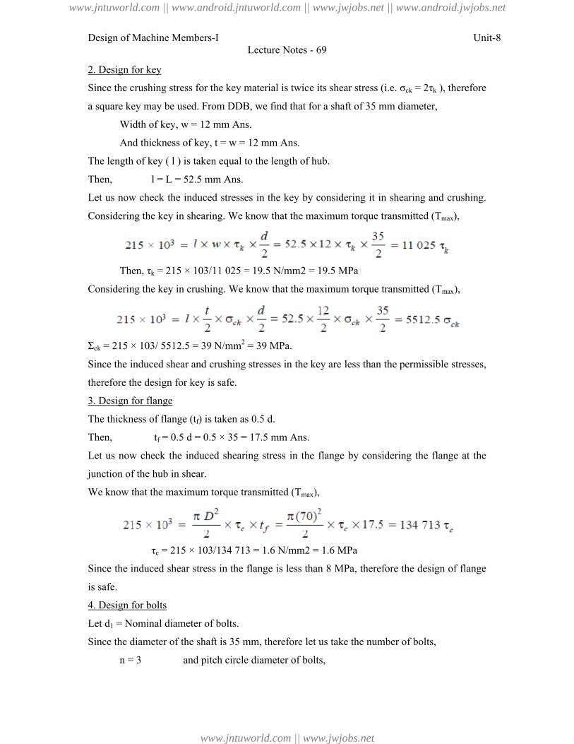
Design of Machine Members-I Unit-8Lecture Notes - 69
2. Design for key
Since the crushing stress for the key material is twice its shear stress (i.e. σck = 2τk ), therefore
a square key may be used. From DDB, we find that for a shaft of 35 mm diameter,
Width of key, w = 12 mm Ans.
And thickness of key, t = w = 12 mm Ans.
The length of key ( l ) is taken equal to the length of hub.
Then, l = L = 52.5 mm Ans.
Let us now check the induced stresses in the key by considering it in shearing and crushing.
Considering the key in shearing. We know that the maximum torque transmitted (Tmax),
Then, τk = 215 × 103/11 025 = 19.5 N/mm2 = 19.5 MPa
Considering the key in crushing. We know that the maximum torque transmitted (Tmax),
Σck = 215 × 103/ 5512.5 = 39 N/mm2 = 39 MPa.
Since the induced shear and crushing stresses in the key are less than the permissible stresses,
therefore the design for key is safe.
3. Design for flange
The thickness of flange (tf) is taken as 0.5 d.
Then, tf = 0.5 d = 0.5 × 35 = 17.5 mm Ans.
Let us now check the induced shearing stress in the flange by considering the flange at the
junction of the hub in shear.
We know that the maximum torque transmitted (Tmax),
τc = 215 × 103/134 713 = 1.6 N/mm2 = 1.6 MPa
Since the induced shear stress in the flange is less than 8 MPa, therefore the design of flange
is safe.
4. Design for bolts
Let d1 = Nominal diameter of bolts.
Since the diameter of the shaft is 35 mm, therefore let us take the number of bolts,
n = 3 and pitch circle diameter of bolts,
www.jntuworld.com || www.android.jntuworld.com || www.jwjobs.net || www.android.jwjobs.net
www.jntuworld.com || www.jwjobs.net
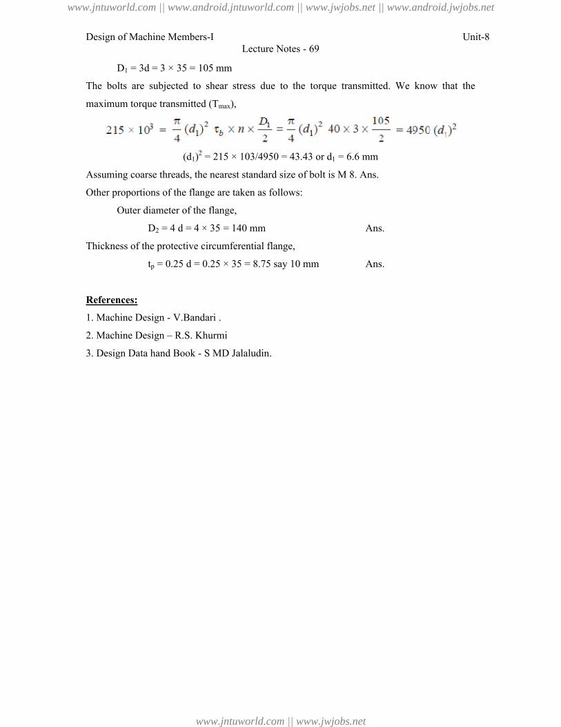
Design of Machine Members-I Unit-8Lecture Notes - 69
D1 = 3d = 3 × 35 = 105 mm
The bolts are subjected to shear stress due to the torque transmitted. We know that the
maximum torque transmitted (Tmax),
(d1)2 = 215 × 103/4950 = 43.43 or d1 = 6.6 mm
Assuming coarse threads, the nearest standard size of bolt is M 8. Ans.
Other proportions of the flange are taken as follows:
Outer diameter of the flange,
D2 = 4 d = 4 × 35 = 140 mm Ans.
Thickness of the protective circumferential flange,
tp = 0.25 d = 0.25 × 35 = 8.75 say 10 mm Ans.
References:
1. Machine Design - V.Bandari .
2. Machine Design – R.S. Khurmi
3. Design Data hand Book - S MD Jalaludin.
www.jntuworld.com || www.android.jntuworld.com || www.jwjobs.net || www.android.jwjobs.net
www.jntuworld.com || www.jwjobs.net
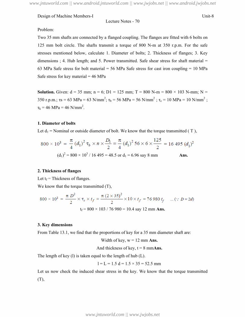
Design of Machine Members-I Unit-8Lecture Notes - 70
Problem:
Two 35 mm shafts are connected by a flanged coupling. The flanges are fitted with 6 bolts on
125 mm bolt circle. The shafts transmit a torque of 800 N-m at 350 r.p.m. For the safe
stresses mentioned below, calculate 1. Diameter of bolts; 2. Thickness of flanges; 3. Key
dimensions ; 4. Hub length; and 5. Power transmitted. Safe shear stress for shaft material =
63 MPa Safe stress for bolt material = 56 MPa Safe stress for cast iron coupling = 10 MPa
Safe stress for key material = 46 MPa
Solution. Given: d = 35 mm; n = 6; D1 = 125 mm; T = 800 N-m = 800 × 103 N-mm; N =
350 r.p.m.; τs = 63 MPa = 63 N/mm2; τb = 56 MPa = 56 N/mm2 ; τc = 10 MPa = 10 N/mm2 ;
τk = 46 MPa = 46 N/mm2.
1. Diameter of bolts
Let d1 = Nominal or outside diameter of bolt. We know that the torque transmitted ( T ),
(d1)2 = 800 × 103 / 16 495 = 48.5 or d1 = 6.96 say 8 mm Ans.
2. Thickness of flanges
Let tf = Thickness of flanges.
We know that the torque transmitted (T),
tf = 800 × 103 / 76 980 = 10.4 say 12 mm Ans.
3. Key dimensions
From Table 13.1, we find that the proportions of key for a 35 mm diameter shaft are:
Width of key, w = 12 mm Ans.
And thickness of key, t = 8 mmAns.
The length of key (l) is taken equal to the length of hub (L).
l = L = 1.5 d = 1.5 × 35 = 52.5 mm
Let us now check the induced shear stress in the key. We know that the torque transmitted
(T),
www.jntuworld.com || www.android.jntuworld.com || www.jwjobs.net || www.android.jwjobs.net
www.jntuworld.com || www.jwjobs.net
Design of Machine Members-I
τk = 800 × 103 / 11 025 = 72.5 N/mm2
Since the induced shear stress in the key is more than the given safe stress (46 MPa),
therefore let us find the length of key by substituting the value of τ
equation, i.e.
l = 800 × 103 / 9660 = 82.8 say 85 mm
4. Hub length
Since the length of key is taken equal to the length of hub, therefore we shall take hub length,
5. Power transmitted
We know that the power transmitted,
Problem:
The shaft and the flange of a marine engine are to be designed for flange
the flange is forged on the end of the shaft. The following particulars are to
design:
Power of the engine = 3 MW
Speed of the engine = 100 r.p.m.
Permissible shear stress in bolts and shaft
Number of bolts used = 8
Pitch circle diameter of bolts
Find: 1. diameter of shaft; 2. diameter of bolts;
flange.
Solution. Given: P = 3 MW = 3 × 10⁶ W;
8; D1 = 1.6 d
1. Diameter of shaft
Let d = Diameter of shaft.
We know that the torque transmitted by the shaft,
Lecture Notes - 70
= 800 × 103 / 11 025 = 72.5 N/mm2
Since the induced shear stress in the key is more than the given safe stress (46 MPa),
ength of key by substituting the value of τk = 46 MPa in the above
= 800 × 103 / 9660 = 82.8 say 85 mm Ans.
Since the length of key is taken equal to the length of hub, therefore we shall take hub length,
L = l = 85 mm Ans.
We know that the power transmitted,
The shaft and the flange of a marine engine are to be designed for flange coupling, in which
the flange is forged on the end of the shaft. The following particulars are to considered in
3 MW
100 r.p.m.
Permissible shear stress in bolts and shaft = 60 MPa
8
Pitch circle diameter of bolts = 1.6 × Diameter of shaft
: 1. diameter of shaft; 2. diameter of bolts; 3. thickness of flange; and 4. diameter of
= 3 MW = 3 × 10⁶ W; N = 100 r.p.m.; τb = τs = 60 MPa = 60 N/mm
We know that the torque transmitted by the shaft,
Unit-8
Since the induced shear stress in the key is more than the given safe stress (46 MPa),
= 46 MPa in the above
Since the length of key is taken equal to the length of hub, therefore we shall take hub length,
coupling, in which
considered in the
3. thickness of flange; and 4. diameter of
= 60 MPa = 60 N/mm2; n =
www.jntuworld.com || www.android.jntuworld.com || www.jwjobs.net || www.android.jwjobs.net
www.jntuworld.com || www.jwjobs.net
Design of Machine Members-I Unit-8Lecture Notes - 70
We also know that torque transmitted by the shaft (T),
d3 = 286 × 106 / 11.78 = 24.3 × 10⁶
or d = 2.89 × 102 = 289 say 300 mm Ans.
2. Diameter of bolts
Let d1 = Nominal diameter of bolts.
The bolts are subjected to shear stress due to the torque transmitted. We know that torque
transmitted (T ),
= 90 490 (d1)2 ... (Since D1 = 1.6 d)
So, (d1)2 = 286 × 106 / 90 490 = 3160 or d1 = 56.2 mm
Assuming coarse threads, the standard diameter of the bolt is 60 mm (M 60). The taper on the
bolt may be taken from 1 in 20 to 1 in 40. Ans.
3. Thickness of flange
The thickness of flange (tf ) is taken as d / 3.
So, tf = d / 3 = 300/3 = 100 mm Ans.
Let us now check the induced shear stress in the flange by considering the flange at the
junction of the shaft in shear. We know that the torque transmitted (T),
τs = 286 × 106 / 14.14 × 106 = 20.2 N/mm2 = 20.2 MPa
Since the induced shear stress in the *flange is less than the permissible shear stress of 60
MPa, therefore the thickness of flange (tf = 100 mm) is safe.
4. Diameter of flange
The diameter of flange (D2) is taken as 2.2 d.
So, D2 = 2.2 d = 2.2 × 300 = 660 mm Ans.
References:
1. Machine Design - V.Bandari .
www.jntuworld.com || www.android.jntuworld.com || www.jwjobs.net || www.android.jwjobs.net
www.jntuworld.com || www.jwjobs.net

Design of Machine Members-I Unit-8Lecture Notes - 70
2. Machine Design – R.S. Khurmi
3. Design Data hand Book - S MD Jalaludin.
www.jntuworld.com || www.android.jntuworld.com || www.jwjobs.net || www.android.jwjobs.net
www.jntuworld.com || www.jwjobs.net
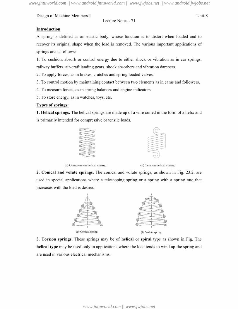
Design of Machine Members-I
Introduction
A spring is defined as an elastic body, whose function is to distort when loaded and to
recover its original shape when the load is removed. The various important applications of
springs are as follows:
1. To cushion, absorb or control energy
railway buffers, air-craft landing gears, shock absorbers and vibration dampers.
2. To apply forces, as in brakes, clutches and spring loaded valves.
3. To control motion by maintaining contact between t
4. To measure forces, as in spring balances and engine indicators.
5. To store energy, as in watches, toys, etc.
Types of springs:
1. Helical springs. The helical springs are made up of a wire coiled in the form of a h
is primarily intended for compressive or tensile loads
2. Conical and volute springs.
used in special applications where a telescoping spring or a spring with a spring rate that
increases with the load is desired
3. Torsion springs. These springs may be of
helical type may be used only in applications where the load tends to wind up the spring and
are used in various electrical mechanisms
Lecture Notes - 71
A spring is defined as an elastic body, whose function is to distort when loaded and to
recover its original shape when the load is removed. The various important applications of
To cushion, absorb or control energy due to either shock or vibration as in car springs,
craft landing gears, shock absorbers and vibration dampers.
To apply forces, as in brakes, clutches and spring loaded valves.
To control motion by maintaining contact between two elements as in cams and followers.
To measure forces, as in spring balances and engine indicators.
To store energy, as in watches, toys, etc.
The helical springs are made up of a wire coiled in the form of a h
is primarily intended for compressive or tensile loads.
. The conical and volute springs, as shown in Fig. 23.2, are
in special applications where a telescoping spring or a spring with a spring rate that
load is desired
These springs may be of helical or spiral type as shown in Fig.
may be used only in applications where the load tends to wind up the spring and
in various electrical mechanisms.
Unit-8
A spring is defined as an elastic body, whose function is to distort when loaded and to
recover its original shape when the load is removed. The various important applications of
due to either shock or vibration as in car springs,
wo elements as in cams and followers.
The helical springs are made up of a wire coiled in the form of a helix and
The conical and volute springs, as shown in Fig. 23.2, are
in special applications where a telescoping spring or a spring with a spring rate that
type as shown in Fig. The
may be used only in applications where the load tends to wind up the spring and
www.jntuworld.com || www.android.jntuworld.com || www.jwjobs.net || www.android.jwjobs.net
www.jntuworld.com || www.jwjobs.net
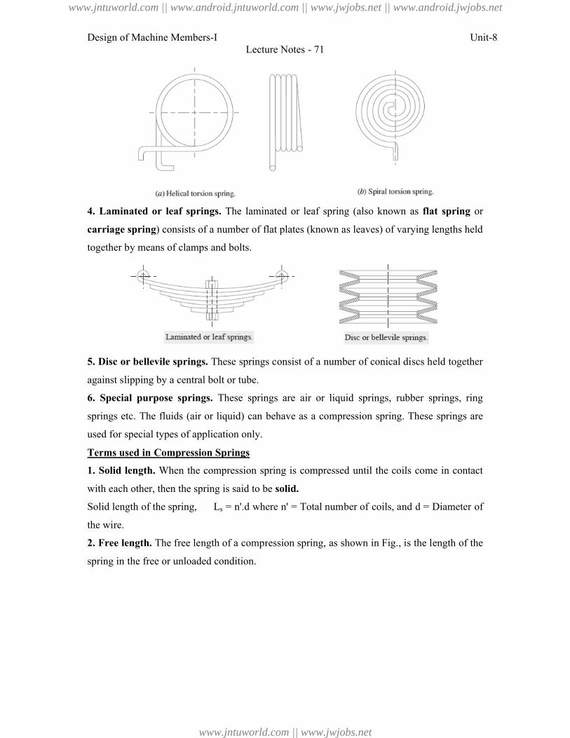
Design of Machine Members-I
4. Laminated or leaf springs.
carriage spring) consists of a number of flat plates (known as leaves) of varying lengths held
together by means of clamps and bolts.
5. Disc or bellevile springs. These springs consist of a number of conical discs held together
against slipping by a central bolt or tube.
6. Special purpose springs. These springs are air or liquid springs, rubber springs, ring
springs etc. The fluids (air or liquid) can behave as a co
used for special types of application only.
Terms used in Compression Springs
1. Solid length. When the compression spring is compressed until the coils come in contact
with each other, then the spring is said to be
Solid length of the spring, Ls
the wire.
2. Free length. The free length of a compr
spring in the free or unloaded condition.
Lecture Notes - 71
. The laminated or leaf spring (also known as flat spring
) consists of a number of flat plates (known as leaves) of varying lengths held
means of clamps and bolts.
hese springs consist of a number of conical discs held together
against slipping by a central bolt or tube.
These springs are air or liquid springs, rubber springs, ring
etc. The fluids (air or liquid) can behave as a compression spring. These springs are
types of application only.
Terms used in Compression Springs
When the compression spring is compressed until the coils come in contact
with each other, then the spring is said to be solid.
= n'.d where n' = Total number of coils, and d = Diameter of
The free length of a compression spring, as shown in Fig., is the length of
spring in the free or unloaded condition.
Unit-8
flat spring or
) consists of a number of flat plates (known as leaves) of varying lengths held
hese springs consist of a number of conical discs held together
These springs are air or liquid springs, rubber springs, ring
mpression spring. These springs are
When the compression spring is compressed until the coils come in contact
= Diameter of
, is the length of the
www.jntuworld.com || www.android.jntuworld.com || www.jwjobs.net || www.android.jwjobs.net
www.jntuworld.com || www.jwjobs.net
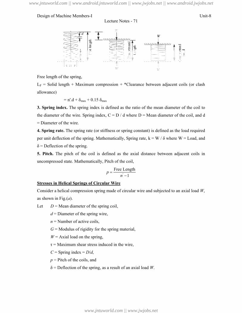
Design of Machine Members-I
Free length of the spring,
LF = Solid length + Maximum compression + *Clearance between
allowance)
= n'.d + δmax + 0.15 δ
3. Spring index. The spring index is defined as the ratio of the mean diameter of the coil to
the diameter of the wire. Spring index,
= Diameter of the wire.
4. Spring rate. The spring rate (or stiffness or spring constant) is defined as the load required
per unit deflection of the spring. Mathematically,
δ = Deflection of the spring.
5. Pitch. The pitch of the coil is defined as the axial distance between adjacent coils in
uncompressed state. Mathematically,
Stresses in Helical Springs of Circular Wire
Consider a helical compression spring made of circular wire and subjected to an axial load
as shown in Fig.(a).
Let D = Mean diameter of the spring coil,
d = Diameter of the spring wire,
n = Number of active coils,
G = Modulus of rigidity for the spring material,
W = Axial load on the spring,
τ = Maximum shear stress induced in the wire,
C = Spring index = D/d,
p = Pitch of the coils, and
δ = Deflection of the spring, as a result of an axial load
Lecture Notes - 71
= Solid length + Maximum compression + *Clearance between adjacent coils (or clash
+ 0.15 δmax
The spring index is defined as the ratio of the mean diameter of the coil to
Spring index, C = D / d where D = Mean diameter of the coil, and
The spring rate (or stiffness or spring constant) is defined as the load required
per unit deflection of the spring. Mathematically, Spring rate, k = W / δ where W
The pitch of the coil is defined as the axial distance between adjacent coils in
uncompressed state. Mathematically, Pitch of the coil,
'
Free Length
1p
n
Helical Springs of Circular Wire
Consider a helical compression spring made of circular wire and subjected to an axial load
= Mean diameter of the spring coil,
= Diameter of the spring wire,
= Number of active coils,
Modulus of rigidity for the spring material,
= Axial load on the spring,
τ = Maximum shear stress induced in the wire,
= Pitch of the coils, and
δ = Deflection of the spring, as a result of an axial load W.
Unit-8
adjacent coils (or clash
The spring index is defined as the ratio of the mean diameter of the coil to
= Mean diameter of the coil, and d
The spring rate (or stiffness or spring constant) is defined as the load required
W = Load, and
The pitch of the coil is defined as the axial distance between adjacent coils in
Consider a helical compression spring made of circular wire and subjected to an axial load W,
www.jntuworld.com || www.android.jntuworld.com || www.jwjobs.net || www.android.jwjobs.net
www.jntuworld.com || www.jwjobs.net
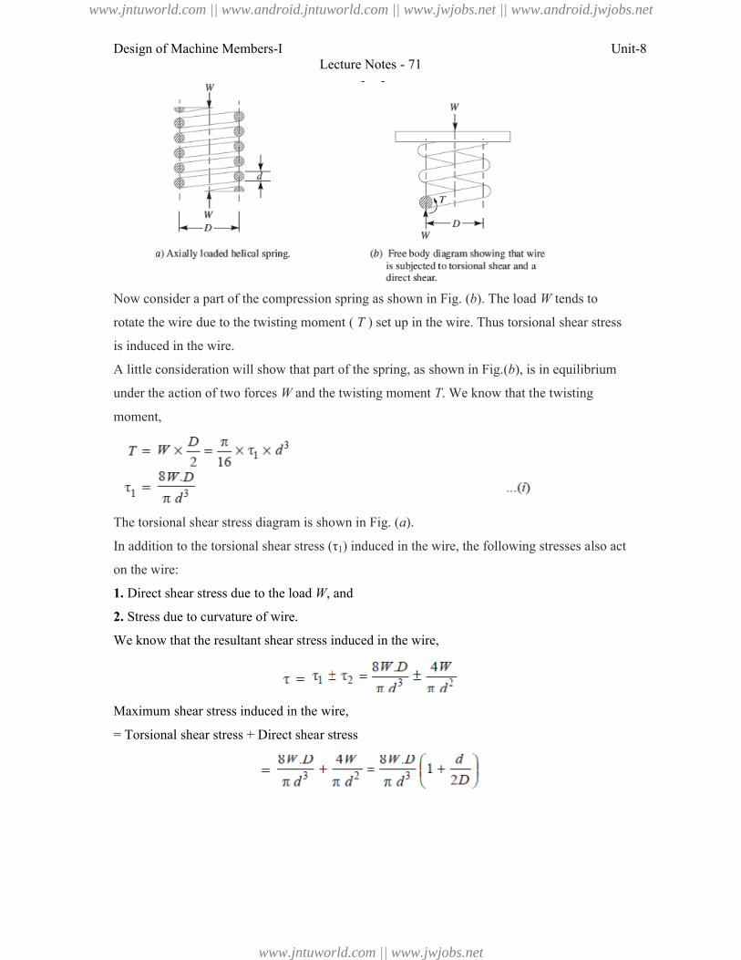
Design of Machine Members-I
Now consider a part of the compressi
rotate the wire due to the twisting moment (
is induced in the wire.
A little consideration will show that part
under the action of two forces W
moment,
The torsional shear stress diagram is shown in Fig. (
In addition to the torsional shear stress (τ
on the wire:
1. Direct shear stress due to the load
2. Stress due to curvature of wire.
We know that the resultant shear stress induced in the wire,
Maximum shear stress induced in the wire,
= Torsional shear stress + Direct shear stress
Lecture Notes - 71
of the compression spring as shown in Fig. (b). The load W
rotate the wire due to the twisting moment ( T ) set up in the wire. Thus torsional shear stress
A little consideration will show that part of the spring, as shown in Fig.(b), is in equilibrium
W and the twisting moment T. We know that the twisting
The torsional shear stress diagram is shown in Fig. (a).
In addition to the torsional shear stress (τ1) induced in the wire, the following stresses also act
Direct shear stress due to the load W, and
Stress due to curvature of wire.
We know that the resultant shear stress induced in the wire,
Maximum shear stress induced in the wire,
irect shear stress
Unit-8
W tends to
) set up in the wire. Thus torsional shear stress
), is in equilibrium
. We know that the twisting
following stresses also act
www.jntuworld.com || www.android.jntuworld.com || www.jwjobs.net || www.android.jwjobs.net
www.jntuworld.com || www.jwjobs.net
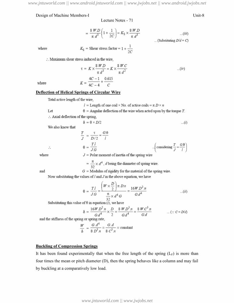
Design of Machine Members-I
Deflection of Helical Springs of Circular Wire
Buckling of Compression Springs
It has been found experimentally that when the free length of the spring (
four times the mean or pitch diameter (
by buckling at a comparatively low load.
Lecture Notes - 71
Deflection of Helical Springs of Circular Wire
Buckling of Compression Springs
It has been found experimentally that when the free length of the spring (LF) is more than
times the mean or pitch diameter (D), then the spring behaves like a column and may fail
at a comparatively low load.
Unit-8
) is more than
behaves like a column and may fail
www.jntuworld.com || www.android.jntuworld.com || www.jwjobs.net || www.android.jwjobs.net
www.jntuworld.com || www.jwjobs.net
Design of Machine Members-I Unit-8Lecture Notes - 71
Wcr = k × KB × LF
where k = Spring rate or stiffness of the spring = W/δ,
LF = Free length of the spring, and
KB = Buckling factor depending upon the ratio LF / D.
Surge in springs
When one end of a helical spring is resting on a rigid support and the other end is loaded
suddenly, then all the coils of the spring will not suddenly deflect equally, because some time
is required for the propagation of stress along the spring wire. A little consideration will show
that in the beginning, the end coils of the spring in contact with the applied load takes up
whole of the deflection and then it transmits a large part of its deflection to the adjacent coils.
In this way, a wave of compression propagates through the coils to the supported end from
where it is reflected back to the deflected end.
Where d = Diameter of the wire,
D = Mean diameter of the spring,
n = Number of active turns,
G = Modulus of rigidity,
g = Acceleration due to gravity, and
ρ = Density of the material of the spring.
References:
1. Machine Design - V.Bandari .
2. Machine Design – R.S. Khurmi
3. Design Data hand Book - S MD Jalaludin.
www.jntuworld.com || www.android.jntuworld.com || www.jwjobs.net || www.android.jwjobs.net
www.jntuworld.com || www.jwjobs.net
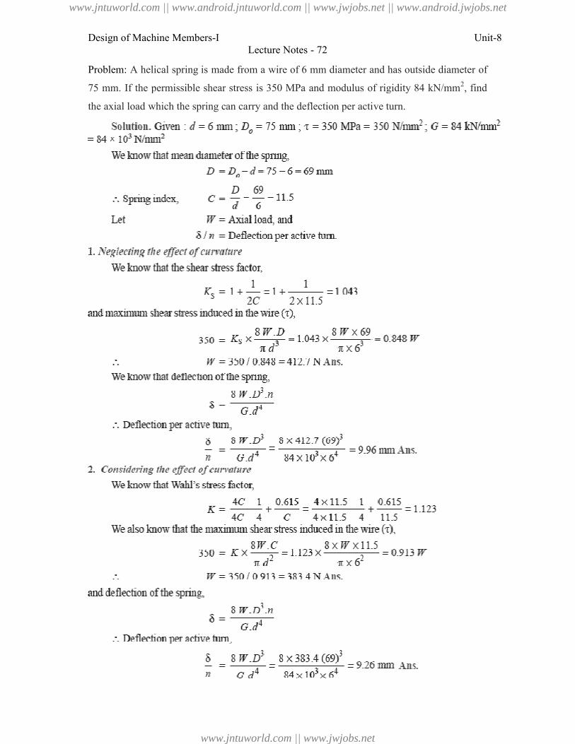
Design of Machine Members-I
Problem: A helical spring is made from a wire of 6 mm diameter and has outside diameter
75 mm. If the permissible shear stress is 350 MPa and modulus of rigidity 84 kN/mm
the axial load which the spring can carry and the deflection per active
Lecture Notes - 72
A helical spring is made from a wire of 6 mm diameter and has outside diameter
75 mm. If the permissible shear stress is 350 MPa and modulus of rigidity 84 kN/mm
axial load which the spring can carry and the deflection per active turn.
Unit-8
A helical spring is made from a wire of 6 mm diameter and has outside diameter of
75 mm. If the permissible shear stress is 350 MPa and modulus of rigidity 84 kN/mm2, find
www.jntuworld.com || www.android.jntuworld.com || www.jwjobs.net || www.android.jwjobs.net
www.jntuworld.com || www.jwjobs.net
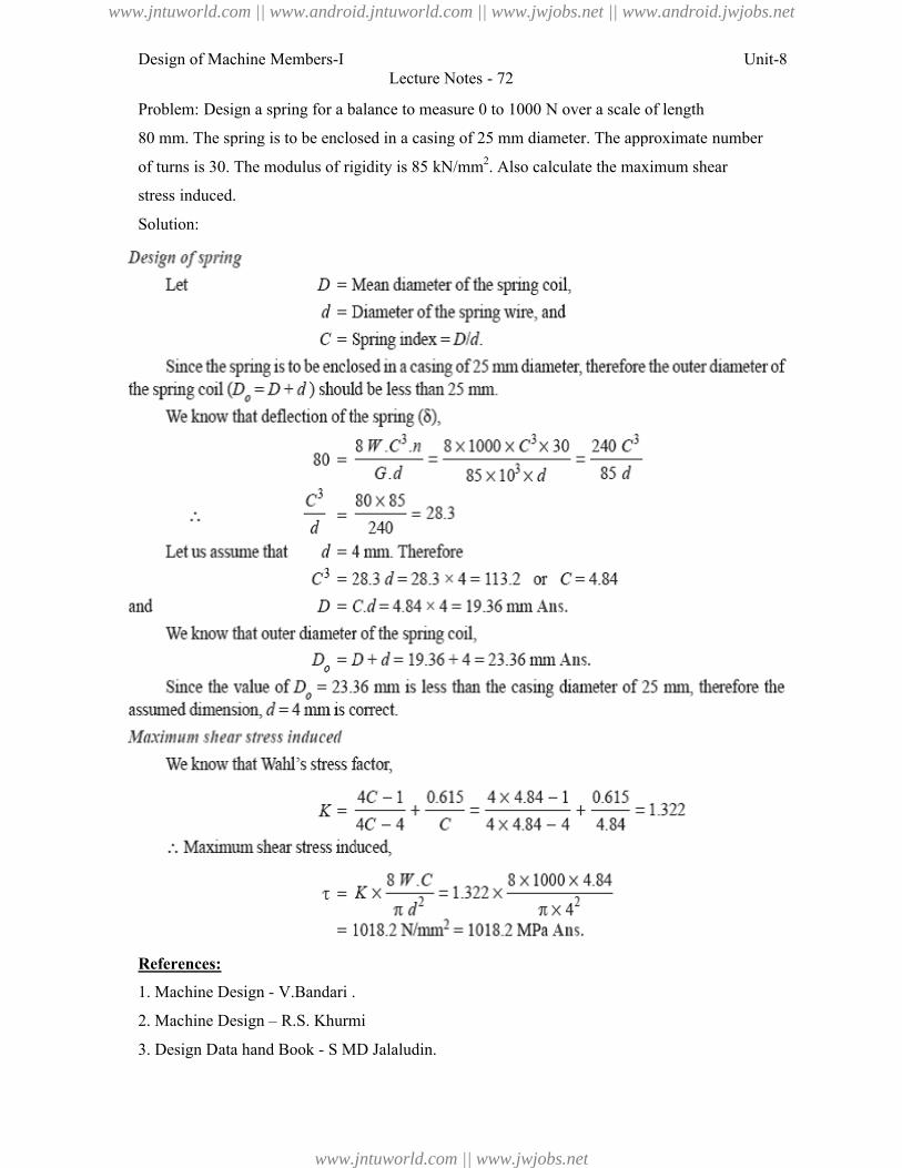
Design of Machine Members-I
Problem: Design a spring for a balance to measure 0 to 1000 N over a scale of length
80 mm. The spring is to be enclosed in a casing of 25 mm diameter. The approximate number
of turns is 30. The modulus of rigidity is 85 kN/mm
stress induced.
Solution:
References:
1. Machine Design - V.Bandari .
2. Machine Design – R.S. Khurmi
3. Design Data hand Book - S MD Jalaludin
Lecture Notes - 72
Design a spring for a balance to measure 0 to 1000 N over a scale of length
80 mm. The spring is to be enclosed in a casing of 25 mm diameter. The approximate number
is 30. The modulus of rigidity is 85 kN/mm2. Also calculate the maximum shear
V.Bandari .
R.S. Khurmi
S MD Jalaludin.
Unit-8
Design a spring for a balance to measure 0 to 1000 N over a scale of length
80 mm. The spring is to be enclosed in a casing of 25 mm diameter. The approximate number
maximum shear
www.jntuworld.com || www.android.jntuworld.com || www.jwjobs.net || www.android.jwjobs.net
www.jntuworld.com || www.jwjobs.net
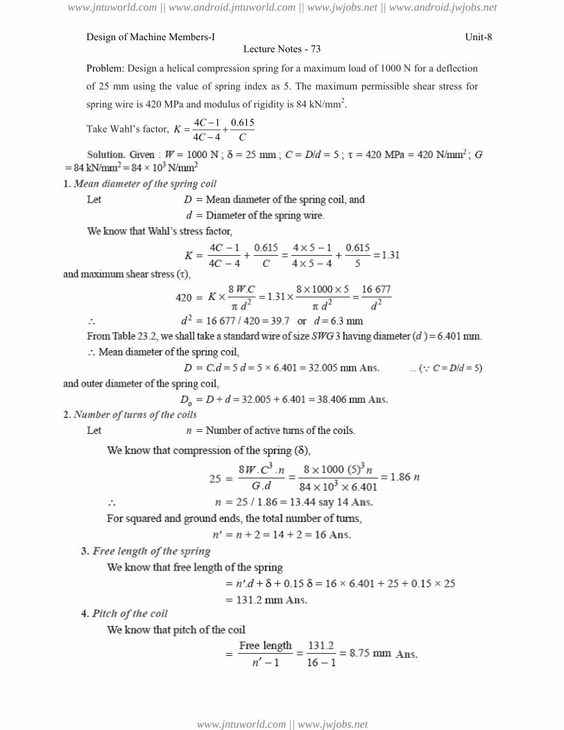
Design of Machine Members-I
Problem: Design a helical compression spring for a maximum load of 1000 N for a
of 25 mm using the value of spring index as 5.
spring wire is 420 MPa and modulus of rigidity is
Take Wahl’s factor, 4 1 0.615
4 4
CK
C C
Lecture Notes - 73
Design a helical compression spring for a maximum load of 1000 N for a
of 25 mm using the value of spring index as 5. The maximum permissible shear stress for
spring wire is 420 MPa and modulus of rigidity is 84 kN/mm2.
4 1 0.615
4 4C C
Unit-8
Design a helical compression spring for a maximum load of 1000 N for a deflection
The maximum permissible shear stress for
www.jntuworld.com || www.android.jntuworld.com || www.jwjobs.net || www.android.jwjobs.net
www.jntuworld.com || www.jwjobs.net
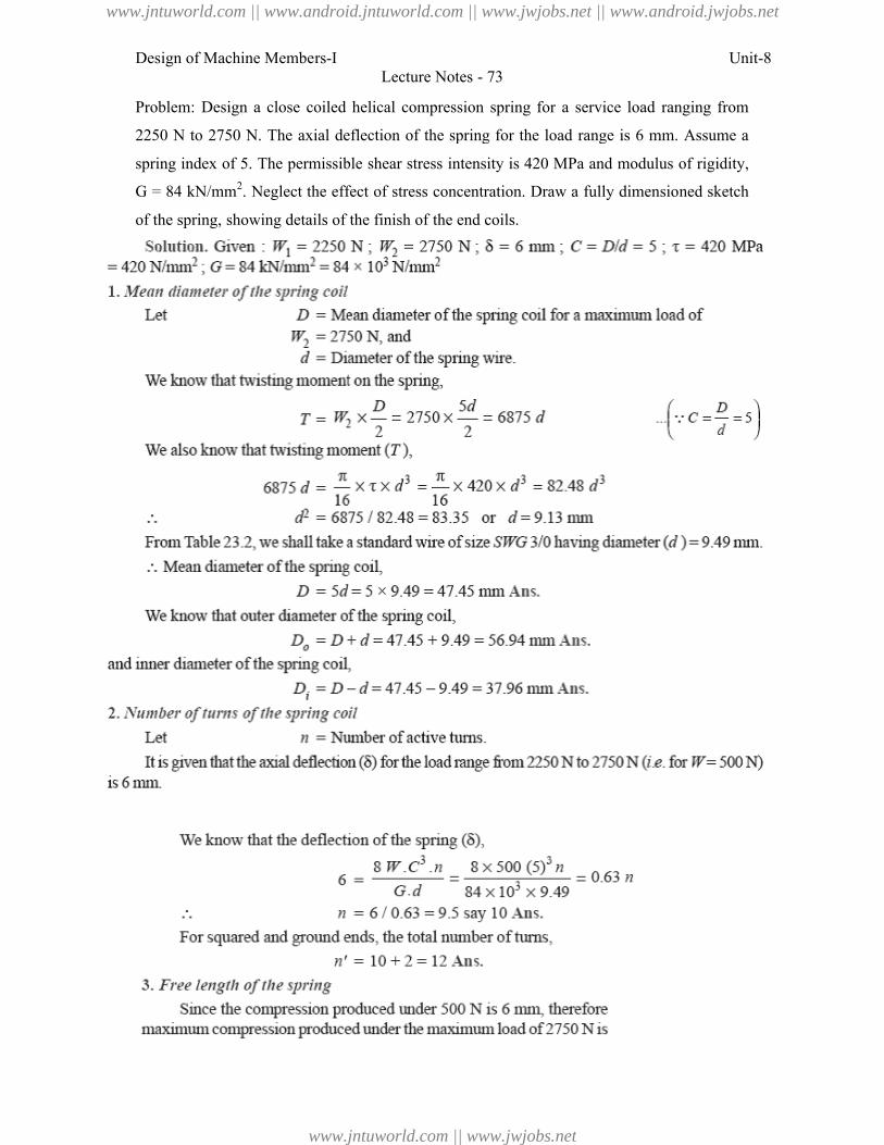
Design of Machine Members-I
Problem: Design a close coiled helical compression spring for a service load ranging
2250 N to 2750 N. The axial deflection of the spring for the load range is 6 mm. Assume a
spring index of 5. The permissible
G = 84 kN/mm2. Neglect the effect of stress concentration. Draw a fully dimensioned sketch
of the spring, showing details of the finish of the end coils
Lecture Notes - 73
Design a close coiled helical compression spring for a service load ranging
2250 N to 2750 N. The axial deflection of the spring for the load range is 6 mm. Assume a
spring index of 5. The permissible shear stress intensity is 420 MPa and modulus of rigidity,
Neglect the effect of stress concentration. Draw a fully dimensioned sketch
details of the finish of the end coils.
Unit-8
Design a close coiled helical compression spring for a service load ranging from
2250 N to 2750 N. The axial deflection of the spring for the load range is 6 mm. Assume a
shear stress intensity is 420 MPa and modulus of rigidity,
Neglect the effect of stress concentration. Draw a fully dimensioned sketch
www.jntuworld.com || www.android.jntuworld.com || www.jwjobs.net || www.android.jwjobs.net
www.jntuworld.com || www.jwjobs.net
Design of Machine Members-I
References:
1. Machine Design - V.Bandari .
2. Machine Design – R.S. Khurmi
3. Design Data hand Book - S MD Jalaludin
Lecture Notes - 73
V.Bandari .
R.S. Khurmi
S MD Jalaludin.
Unit-8
www.jntuworld.com || www.android.jntuworld.com || www.jwjobs.net || www.android.jwjobs.net
www.jntuworld.com || www.jwjobs.net
Design of Machine Members-I Unit-8Lecture Notes - 74
Energy Stored in Helical Springs of Circular Wire
We know that the springs are used for storing energy which is equal to the work done on it by
some external load.
Let W = Load applied on the spring, and
δ = Deflection produced in the spring due to the load W.
Assuming that the load is applied gradually, the energy stored in a spring is,
We have already discussed that the maximum shear stress induced in the spring wire,
We know that deflection of the spring,
Substituting the values of W and δ in equation (i), we have
Where V = Volume of the spring wire
= Length of spring wire × Cross-sectional area of spring wire
Helical Springs Subjected to Fatigue Loading
The helical springs subjected to fatigue loading are designed by using the Soderberg line
method. The spring materials are usually tested for torsional endurance strength under a
repeated stress that varies from zero to a maximum. Since the springs are ordinarily loaded in
one direction only (the load in springs is never reversed in nature), therefore a modified
Soderberg diagram is used for springs, as shown in Fig.
The endurance limit for reversed loading is shown at point A where the mean shear
stress is equal to τe / 2 and the variable shear stress is also equal to τe / 2. A line drawn from
A to B (the yield point in shear, τy) gives the Soderberg’s failure stress line. If a suitable
factor of safety (F.S.) is applied to the yield strength (τy), a safe stress line CD may be drawn
www.jntuworld.com || www.android.jntuworld.com || www.jwjobs.net || www.android.jwjobs.net
www.jntuworld.com || www.jwjobs.net
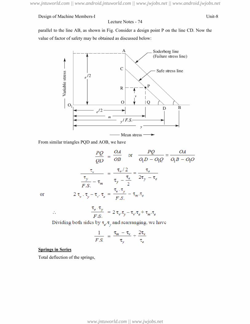
Design of Machine Members-I
parallel to the line AB, as shown
value of factor of safety may be obtained as discussed below
From similar triangles PQD and
Springs in Series
Total deflection of the springs,
Lecture Notes - 74
, as shown in Fig. Consider a design point P on the line
obtained as discussed below:
and AOB, we have
Unit-8
on the line CD. Now the
www.jntuworld.com || www.android.jntuworld.com || www.jwjobs.net || www.android.jwjobs.net
www.jntuworld.com || www.jwjobs.net
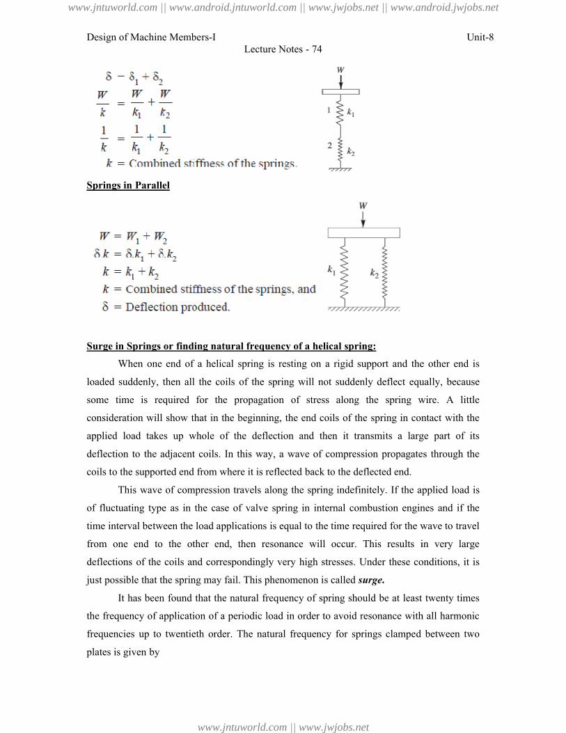
Design of Machine Members-I
Springs in Parallel
Surge in Springs or finding natural frequency of a helical spring:
When one end of a helical spring is resting on a rigid support and the other end is
loaded suddenly, then all the coils of the spring will not suddenly deflect equal
some time is required for the propagation of stress along the spring wire. A little
consideration will show that in the
applied load takes up whole of the deflection
deflection to the adjacent coils. In this way, a wave of compression
coils to the supported end from where it is reflected back to the deflected end.
This wave of compression travels along the spring indefinite
of fluctuating type as in the case of valve spring in internal combustion engines and if the
time interval between the load applications is equal to the time required for the wave to travel
from one end to the other end,
deflections of the coils and correspondingly very
just possible that the spring may fail. This phenomenon is
It has been found that the natural freq
the frequency of application of a periodic load in order to avoid resonance with all harmonic
frequencies up to twentieth order. The natural frequency for springs clamped between two
plates is given by
Lecture Notes - 74
Surge in Springs or finding natural frequency of a helical spring:
When one end of a helical spring is resting on a rigid support and the other end is
suddenly, then all the coils of the spring will not suddenly deflect equal
required for the propagation of stress along the spring wire. A little
consideration will show that in the beginning, the end coils of the spring in contact with the
applied load takes up whole of the deflection and then it transmits a large part of its
deflection to the adjacent coils. In this way, a wave of compression propagates through the
coils to the supported end from where it is reflected back to the deflected end.
This wave of compression travels along the spring indefinitely. If the applied load is
type as in the case of valve spring in internal combustion engines and if the
load applications is equal to the time required for the wave to travel
from one end to the other end, then resonance will occur. This results in very large
deflections of the coils and correspondingly very high stresses. Under these conditions, it is
just possible that the spring may fail. This phenomenon is called surge.
It has been found that the natural frequency of spring should be at least twenty times
of application of a periodic load in order to avoid resonance with all harmonic
twentieth order. The natural frequency for springs clamped between two
Unit-8
When one end of a helical spring is resting on a rigid support and the other end is
suddenly, then all the coils of the spring will not suddenly deflect equally, because
required for the propagation of stress along the spring wire. A little
beginning, the end coils of the spring in contact with the
ts a large part of its
propagates through the
ly. If the applied load is
type as in the case of valve spring in internal combustion engines and if the
load applications is equal to the time required for the wave to travel
resonance will occur. This results in very large
high stresses. Under these conditions, it is
least twenty times
of application of a periodic load in order to avoid resonance with all harmonic
twentieth order. The natural frequency for springs clamped between two
www.jntuworld.com || www.android.jntuworld.com || www.jwjobs.net || www.android.jwjobs.net
www.jntuworld.com || www.jwjobs.net
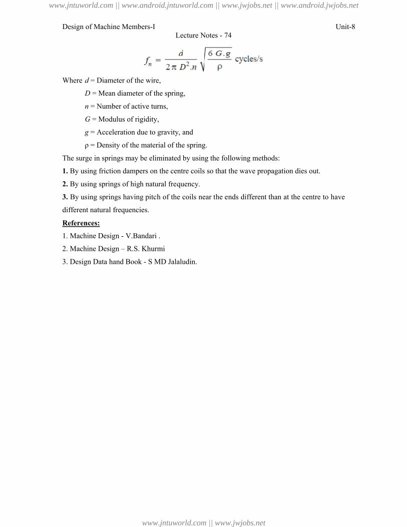
Design of Machine Members-I Unit-8Lecture Notes - 74
Where d = Diameter of the wire,
D = Mean diameter of the spring,
n = Number of active turns,
G = Modulus of rigidity,
g = Acceleration due to gravity, and
ρ = Density of the material of the spring.
The surge in springs may be eliminated by using the following methods:
1. By using friction dampers on the centre coils so that the wave propagation dies out.
2. By using springs of high natural frequency.
3. By using springs having pitch of the coils near the ends different than at the centre to have
different natural frequencies.
References:
1. Machine Design - V.Bandari .
2. Machine Design – R.S. Khurmi
3. Design Data hand Book - S MD Jalaludin.
www.jntuworld.com || www.android.jntuworld.com || www.jwjobs.net || www.android.jwjobs.net
www.jntuworld.com || www.jwjobs.net
Design of Machine Members-I Unit-8Lecture Notes - 75
Energy Stored in Helical Springs of Circular Wire
We know that the springs are used for storing energy which is equal to the work done on it by
some external load.
Let W = Load applied on the spring, and
δ = Deflection produced in the spring due to the load W.
Assuming that the load is applied gradually, the energy stored in a spring is,
We have already discussed that the maximum shear stress induced in the spring wire,
We know that deflection of the spring,
Substituting the values of W and δ in equation (i), we have
Where V = Volume of the spring wire
= Length of spring wire × Cross-sectional area of spring wire
Helical Torsion Springs
The helical torsion springs as shown in Fig., may be made from round, rectangular or square
wire. These are wound in a similar manner as helical compression or tension springs but the
ends are shaped to transmit torque. The primary stress in helical torsion springs is bending
stress whereas in compression or tension springs, the stresses are torsional shear stresses. The
helical torsion springs are widely used for transmitting small torques as in door hinges, brush
holders in electric motors, automobile starters etc. A little consideration will show that the
radius of curvature of the coils changes when the twisting moment is applied to the spring.
Thus, the wire is under pure bending. According to A.M. Wahl, the bending stress in a helical
torsion spring made of round wire is
www.jntuworld.com || www.android.jntuworld.com || www.jwjobs.net || www.android.jwjobs.net
www.jntuworld.com || www.jwjobs.net
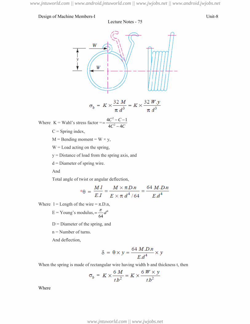
Design of Machine Members-I Unit-8Lecture Notes - 75
Where K = Wahl’s stress factor =2
2
4 1
4 4
C C
C C
C = Spring index,
M = Bending moment = W × y,
W = Load acting on the spring,
y = Distance of load from the spring axis, and
d = Diameter of spring wire.
And
Total angle of twist or angular deflection,
Where l = Length of the wire = π.D.n,
E = Young’s modulus, 4
64d
D = Diameter of the spring, and
n = Number of turns.
And deflection,
When the spring is made of rectangular wire having width b and thickness t, then
Where
www.jntuworld.com || www.android.jntuworld.com || www.jwjobs.net || www.android.jwjobs.net
www.jntuworld.com || www.jwjobs.net
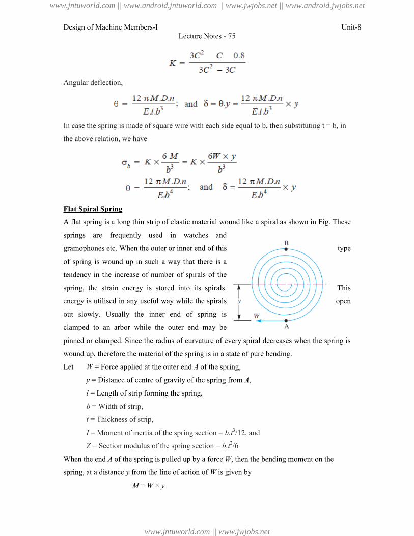
Design of Machine Members-I Unit-8Lecture Notes - 75
Angular deflection,
In case the spring is made of square wire with each side equal to b, then substituting t = b, in
the above relation, we have
Flat Spiral Spring
A flat spring is a long thin strip of elastic material wound like a spiral as shown in Fig. These
springs are frequently used in watches and
gramophones etc. When the outer or inner end of this type
of spring is wound up in such a way that there is a
tendency in the increase of number of spirals of the
spring, the strain energy is stored into its spirals. This
energy is utilised in any useful way while the spirals open
out slowly. Usually the inner end of spring is
clamped to an arbor while the outer end may be
pinned or clamped. Since the radius of curvature of every spiral decreases when the spring is
wound up, therefore the material of the spring is in a state of pure bending.
Let W = Force applied at the outer end A of the spring,
y = Distance of centre of gravity of the spring from A,
l = Length of strip forming the spring,
b = Width of strip,
t = Thickness of strip,
I = Moment of inertia of the spring section = b.t3/12, and
Z = Section modulus of the spring section = b.t2/6
When the end A of the spring is pulled up by a force W, then the bending moment on the
spring, at a distance y from the line of action of W is given by
M = W × y
www.jntuworld.com || www.android.jntuworld.com || www.jwjobs.net || www.android.jwjobs.net
www.jntuworld.com || www.jwjobs.net
Design of Machine Members-I Unit-8Lecture Notes - 75
The greatest bending moment occurs in the spring at B which is at a maximum distance from
the application of W.
Bending moment at B,
MB = Mmax = W × 2y = 2W.y = 2M
Maximum bending stress induced in the spring material,
Assuming that both ends of the spring are clamped, the angular deflection (in radians) of the
spring is given by
And the deflection,
The strain energy stored in the spring
References:
1. Machine Design - V.Bandari .
2. Machine Design – R.S. Khurmi
3. Design Data hand Book - S MD Jalaludin.
www.jntuworld.com || www.android.jntuworld.com || www.jwjobs.net || www.android.jwjobs.net
www.jntuworld.com || www.jwjobs.net
Design of Machine Members-I
Problem: A helical torsion spring of mean diameter 60 mm is made of a round wire of
diameter. If a torque of 6 N-m is applied on the spring, find the bending stress induced and
the angular deflection of the spring in degrees. The spring index is 10
elasticity for the spring material is 200 kN/mm
as 5.5.
Problem: A spiral spring is made of a flat strip 6 mm wide and 0.25 mm thick. The
the strip is 2.5 metres. Assuming the maximum
greatest bending moment, calculate the bending moment, the number of turns to wind up the
spring and the strain energy stored in the spring. Take E = 200 kN/mm
Lecture Notes - 76
A helical torsion spring of mean diameter 60 mm is made of a round wire of
m is applied on the spring, find the bending stress induced and
angular deflection of the spring in degrees. The spring index is 10 and modulus of
spring material is 200 kN/mm2. The number of effective turns may be taken
Problem: A spiral spring is made of a flat strip 6 mm wide and 0.25 mm thick. The
the strip is 2.5 metres. Assuming the maximum stress of 800 MPa to occur at the point of
greatest bending moment, calculate the bending moment, the number of turns to wind up the
and the strain energy stored in the spring. Take E = 200 kN/mm2.
Unit-8
A helical torsion spring of mean diameter 60 mm is made of a round wire of 6 mm
m is applied on the spring, find the bending stress induced and
and modulus of
. The number of effective turns may be taken
Problem: A spiral spring is made of a flat strip 6 mm wide and 0.25 mm thick. The length of
stress of 800 MPa to occur at the point of
greatest bending moment, calculate the bending moment, the number of turns to wind up the
www.jntuworld.com || www.android.jntuworld.com || www.jwjobs.net || www.android.jwjobs.net
www.jntuworld.com || www.jwjobs.net
Design of Machine Members-I
References:
1. Machine Design - V.Bandari .
2. Machine Design – R.S. Khurmi
3. Design Data hand Book - S MD Jalaludin.
Lecture Notes - 76
V.Bandari .
R.S. Khurmi
S MD Jalaludin.
Unit-8
www.jntuworld.com || www.android.jntuworld.com || www.jwjobs.net || www.android.jwjobs.net
www.jntuworld.com || www.jwjobs.net
Design of Machine Members-I Unit-8Lecture Notes - 76
www.jntuworld.com || www.android.jntuworld.com || www.jwjobs.net || www.android.jwjobs.net
www.jntuworld.com || www.jwjobs.net
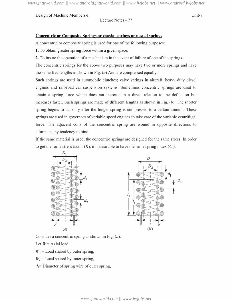
Design of Machine Members-I
Concentric or Composite Springs
A concentric or composite spring is used for one of the following purposes:
1. To obtain greater spring force
2. To insure the operation of a mechanism in the
The concentric springs for the above
the same free lengths as shown in
Such springs are used in automobile
engines and rail-road car suspension
obtain a spring force which does not
increases faster. Such springs are made
spring begins to act only after the longer spring is compressed to a
springs are used in governors of variable speed engines to take
force. The adjacent coils of the concentric spring are wound in opposite directions to
eliminate any tendency to bind.
If the same material is used, the concentric springs are designed for the same stress. In order
to get the same stress factor (K), it is desirable to have
Consider a concentric spring as shown in Fig. (
Let W = Axial load,
W1 = Load shared by outer spring,
W2 = Load shared by inner spring,
d1= Diameter of spring wire of outer spring,
Lecture Notes - 77
Concentric or Composite Springs or coaxial springs or nested springs
A concentric or composite spring is used for one of the following purposes:
within a given space.
mechanism in the event of failure of one of the springs.
The concentric springs for the above two purposes may have two or more springs
n Fig. (a) And are compressed equally.
Such springs are used in automobile clutches; valve springs in aircraft, heavy duty
road car suspension systems. Sometimes concentric springs are used
obtain a spring force which does not increase in a direct relation to the deflection
increases faster. Such springs are made of different lengths as shown in Fig. (b). The shorter
after the longer spring is compressed to a certain amount. These
governors of variable speed engines to take care of the variable centrifugal
coils of the concentric spring are wound in opposite directions to
If the same material is used, the concentric springs are designed for the same stress. In order
), it is desirable to have the same spring index (C
Consider a concentric spring as shown in Fig. (a).
= Load shared by outer spring,
= Load shared by inner spring,
= Diameter of spring wire of outer spring,
Unit-8
the springs.
two purposes may have two or more springs and have
gs in aircraft, heavy duty diesel
Sometimes concentric springs are used to
increase in a direct relation to the deflection but
). The shorter
certain amount. These
care of the variable centrifugal
coils of the concentric spring are wound in opposite directions to
If the same material is used, the concentric springs are designed for the same stress. In order
C ).
www.jntuworld.com || www.android.jntuworld.com || www.jwjobs.net || www.android.jwjobs.net
www.jntuworld.com || www.jwjobs.net
Design of Machine Members-I
d2 = Diameter of spring wire of inner spri
D1 = Mean diameter of outer spring,
D2 = Mean diameter of inner spring,
δ1 = Deflection of outer spring,
δ2 = Deflection of inner spring,
n1 = Number of active turns of outer spring, and
n2 = Number of active turns of inner spring.
Assuming that both the springs are made of same material, then the maximum shear stress
induced in both the springs is approximately same,
When stress factor, K1 = K2, then
If both the springs are effective throughout their working range, then their free length and
deflection are equal, i.e.
When both the springs are compressed until the adjacent coils meet, then the solid length of
both the springs is equal, i.e.
n1.d1 = n2.d2
The equation (ii) may be written as
Now dividing equation (iii) by equation
i.e. the springs should be designed in such a way that the spring index for both the springs is
same. From equations (i) and (iv)
Lecture Notes - 77
= Diameter of spring wire of inner spring,
= Mean diameter of outer spring,
= Mean diameter of inner spring,
= Number of active turns of outer spring, and
= Number of active turns of inner spring.
he springs are made of same material, then the maximum shear stress
induced in both the springs is approximately same, i.e.
, then
If both the springs are effective throughout their working range, then their free length and
When both the springs are compressed until the adjacent coils meet, then the solid length of
be written as
by equation (i), we have
. the springs should be designed in such a way that the spring index for both the springs is
), we have
Unit-8
he springs are made of same material, then the maximum shear stress
If both the springs are effective throughout their working range, then their free length and
When both the springs are compressed until the adjacent coils meet, then the solid length of
. the springs should be designed in such a way that the spring index for both the springs is
www.jntuworld.com || www.android.jntuworld.com || www.jwjobs.net || www.android.jwjobs.net
www.jntuworld.com || www.jwjobs.net
Design of Machine Members-I
From Fig. 23.22 (a), we find that the radial clearance between the two springs,
Usually, the radial clearance between the two springs is taken as
From equation (iv), we find that
Substituting the values of D1 and
Leaf Springs
Leaf springs (also known as flat springs
spring over helical spring is that the ends of the spring may be guided along a definite path as
it deflects to act as a structural member in addition to energy absorbing device. Thus the leaf
springs may carry lateral loads,
Consider a single plate fixed at one end and loaded at
plate may be used as a flat spring.
Let t = Thickness of plate,
b = Width of plate, and
L = Length of plate or distance
from the cantilever end.
We know that the maximum bending moment at the
cantilever end A,
M = W.L
And section modulus,
Bending stress in such a spring,
Lecture Notes - 77
), we find that the radial clearance between the two springs,
ance between the two springs is taken as
------ (vi)
D1 = C.d1, and D2 = C.d2
and D2 in equation (vi), we have
flat springs) are made out of flat plates. The advantage of leaf
spring over helical spring is that the ends of the spring may be guided along a definite path as
deflects to act as a structural member in addition to energy absorbing device. Thus the leaf
may carry lateral loads, brake torque, driving torque etc., in addition to shocks.
Consider a single plate fixed at one end and loaded at the other end as shown in Fig
plate may be used as a flat spring.
te or distance of the load
We know that the maximum bending moment at the
Unit-8
plates. The advantage of leaf
spring over helical spring is that the ends of the spring may be guided along a definite path as
deflects to act as a structural member in addition to energy absorbing device. Thus the leaf
brake torque, driving torque etc., in addition to shocks.
the other end as shown in Fig. This
W
www.jntuworld.com || www.android.jntuworld.com || www.jwjobs.net || www.android.jwjobs.net
www.jntuworld.com || www.jwjobs.net
Design of Machine Members-I
We know that the maximum deflection for a cantilever with concentratedis given by
If the spring is not of cantilever type but it is
and load 2W in the centre, as shown in Fig. then Maximum bending moment in the centre,
M = W.L
Section modulus, Z
Bending stress,
We know that maximum deflection of a simply supported beam loaded in the centre is given
by
From above we see that a spring such as automobile spring (semi
length 2L and loaded in the centre by a load 2
plate of cantilever is cut into a series of
Fig., then equations (i) and (ii) may be written as
And
Lecture Notes - 77
We know that the maximum deflection for a cantilever with concentrated load at the free end
If the spring is not of cantilever type but it is like a simply supported beam, with length 2
in the centre, as shown in Fig. then Maximum bending moment in the centre,
Z = b.t2 / 6
We know that maximum deflection of a simply supported beam loaded in the centre is given
From above we see that a spring such as automobile spring (semi-elliptical spring) with
and loaded in the centre by a load 2W, may be treated as a double cantilever.
plate of cantilever is cut into a series of n strips of width b and these are placed as shown
may be written as
Unit-8
load at the free end
like a simply supported beam, with length 2L
in the centre, as shown in Fig. then Maximum bending moment in the centre,
We know that maximum deflection of a simply supported beam loaded in the centre is given
elliptical spring) with
may be treated as a double cantilever. If the
and these are placed as shown in
www.jntuworld.com || www.android.jntuworld.com || www.jwjobs.net || www.android.jwjobs.net
www.jntuworld.com || www.jwjobs.net
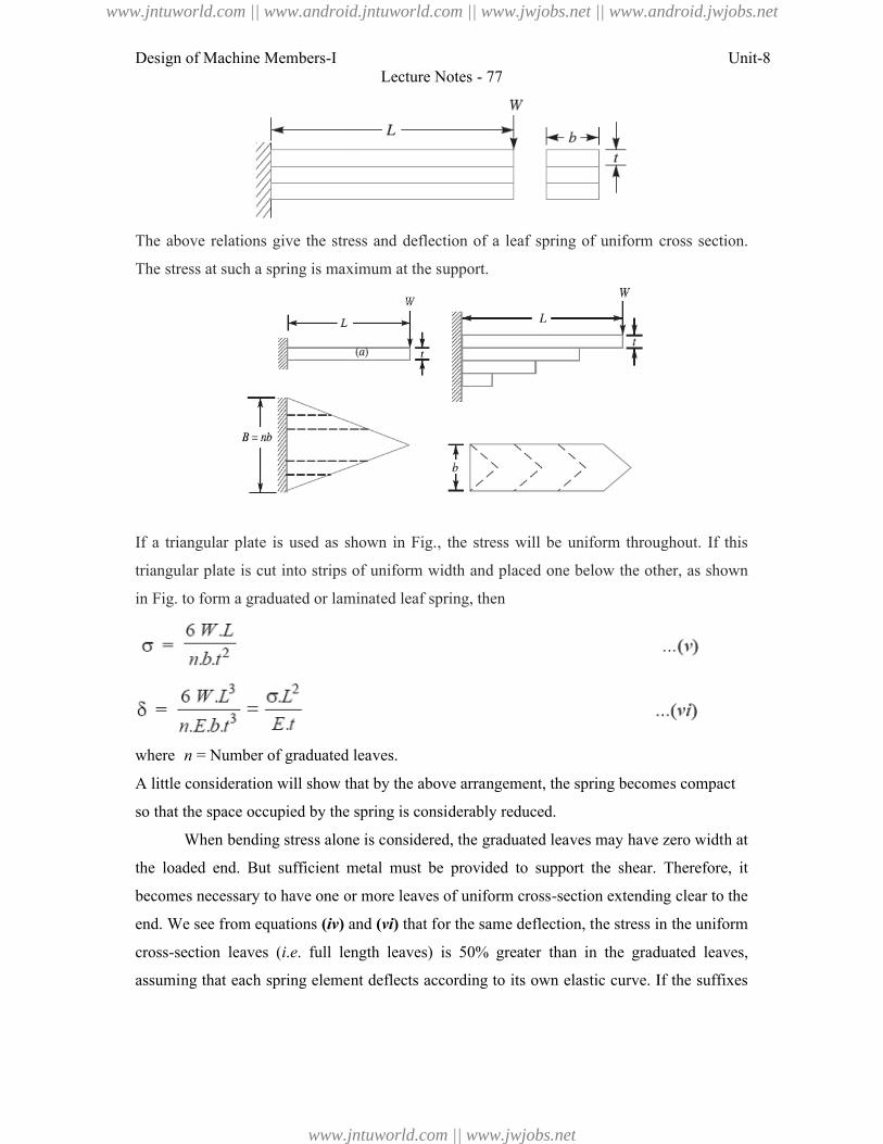
Design of Machine Members-I
The above relations give the stress and deflection
The stress at such a spring is maximum at the support.
If a triangular plate is used as shown in Fig.
triangular plate is cut into strips of uniform width an
in Fig. to form a graduated or laminated leaf spring, then
where n = Number of graduated leaves.
A little consideration will show that by the above arrangement, the spring becomes compact
so that the space occupied by the spring is considerably reduced.
When bending stress alone is considered, the graduated leaves may have zero width at
the loaded end. But sufficient metal must be provided to support the shear. Therefore, it
becomes necessary to have one or
end. We see from equations (iv)
cross-section leaves (i.e. full length
assuming that each spring element deflects according
Lecture Notes - 77
The above relations give the stress and deflection of a leaf spring of uniform cross
stress at such a spring is maximum at the support.
e is used as shown in Fig., the stress will be uniform throughout. If
triangular plate is cut into strips of uniform width and placed one below the other, as shown
to form a graduated or laminated leaf spring, then
= Number of graduated leaves.
A little consideration will show that by the above arrangement, the spring becomes compact
occupied by the spring is considerably reduced.
When bending stress alone is considered, the graduated leaves may have zero width at
loaded end. But sufficient metal must be provided to support the shear. Therefore, it
to have one or more leaves of uniform cross-section extending clear to the
) and (vi) that for the same deflection, the stress in the uniform
. full length leaves) is 50% greater than in the graduated leaves,
g that each spring element deflects according to its own elastic curve. If the suffixes
Unit-8
a leaf spring of uniform cross section.
, the stress will be uniform throughout. If this
d placed one below the other, as shown
A little consideration will show that by the above arrangement, the spring becomes compact
When bending stress alone is considered, the graduated leaves may have zero width at
loaded end. But sufficient metal must be provided to support the shear. Therefore, it
section extending clear to the
that for the same deflection, the stress in the uniform
leaves) is 50% greater than in the graduated leaves,
to its own elastic curve. If the suffixes
www.jntuworld.com || www.android.jntuworld.com || www.jwjobs.net || www.android.jwjobs.net
www.jntuworld.com || www.jwjobs.net
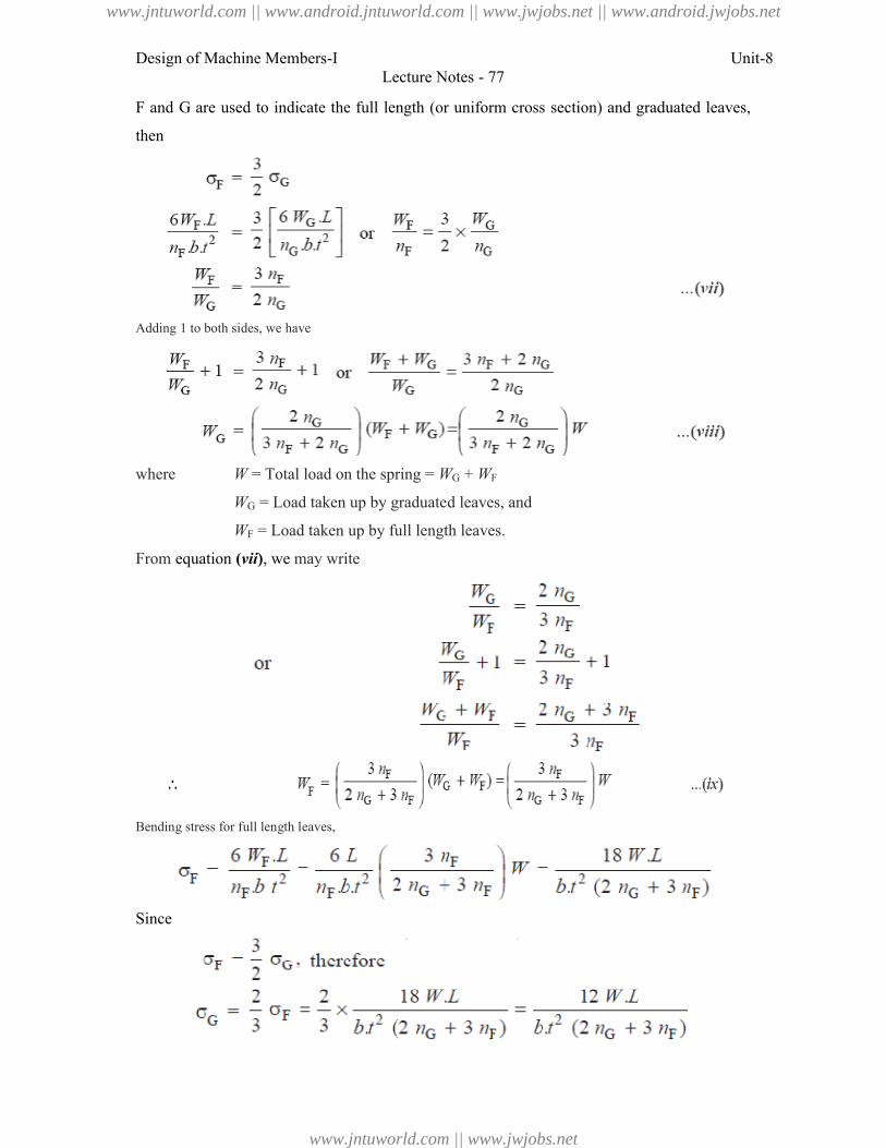
Design of Machine Members-I
F and G are used to indicate the full length (or
then
Adding 1 to both sides, we have
where W = Total load on the spr
WG = Load taken up by graduated leaves, and
WF = Load taken up by full length leaves.
From equation (vii), we may write
Bending stress for full length leaves,
Since
Lecture Notes - 77
to indicate the full length (or uniform cross section) and graduated leaves,
= Total load on the spring = WG + WF
= Load taken up by graduated leaves, and
= Load taken up by full length leaves.
may write
Unit-8
and graduated leaves,
www.jntuworld.com || www.android.jntuworld.com || www.jwjobs.net || www.android.jwjobs.net
www.jntuworld.com || www.jwjobs.net
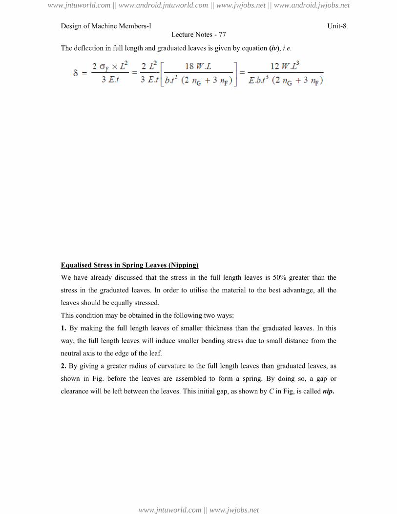
Design of Machine Members-I
The deflection in full length and graduated leaves is given by equation
Equalised Stress in Spring Leaves (Nipping)
We have already discussed that the stress in the full
stress in the graduated leaves. In order to utilise the material to the best advantage, all the
leaves should be equally stressed.
This condition may be obtained in the following two ways:
1. By making the full length leaves of smaller thickness than the graduated leaves. In this
way, the full length leaves will induce smaller bending stress due to small distance from the
neutral axis to the edge of the leaf.
2. By giving a greater radius of curvature to the full length leaves than graduated leaves, as
shown in Fig. before the leaves are
clearance will be left between the leaves. This initial gap, as shown by
Lecture Notes - 77
The deflection in full length and graduated leaves is given by equation (iv), i.e.
Equalised Stress in Spring Leaves (Nipping)
We have already discussed that the stress in the full length leaves is 50% greater than the
In order to utilise the material to the best advantage, all the
leaves should be equally stressed.
This condition may be obtained in the following two ways:
By making the full length leaves of smaller thickness than the graduated leaves. In this
e full length leaves will induce smaller bending stress due to small distance from the
the edge of the leaf.
By giving a greater radius of curvature to the full length leaves than graduated leaves, as
in Fig. before the leaves are assembled to form a spring. By doing so, a gap or
left between the leaves. This initial gap, as shown by C in Fig, is called
Unit-8
length leaves is 50% greater than the
In order to utilise the material to the best advantage, all the
By making the full length leaves of smaller thickness than the graduated leaves. In this
e full length leaves will induce smaller bending stress due to small distance from the
By giving a greater radius of curvature to the full length leaves than graduated leaves, as
assembled to form a spring. By doing so, a gap or
in Fig, is called nip.
www.jntuworld.com || www.android.jntuworld.com || www.jwjobs.net || www.android.jwjobs.net
www.jntuworld.com || www.jwjobs.net
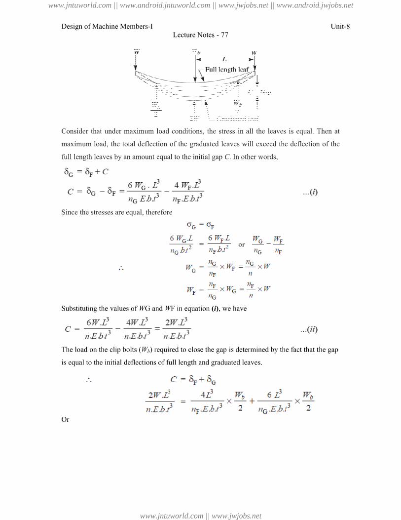
Design of Machine Members-I
Consider that under maximum load conditions, the stress in all the leaves is equal. Then at
maximum load, the total deflection of the graduated leaves will exceed the deflection of the
full length leaves by an amount equal to the initial gap
Since the stresses are equal, therefore
Substituting the values of WG and
The load on the clip bolts (Wb) required to close the gap is determined by the fact that the gap
is equal to the initial deflections of full length and graduated leaves.
Or
Lecture Notes - 77
Consider that under maximum load conditions, the stress in all the leaves is equal. Then at
the total deflection of the graduated leaves will exceed the deflection of the
length leaves by an amount equal to the initial gap C. In other words,
Since the stresses are equal, therefore
G and WF in equation (i), we have
) required to close the gap is determined by the fact that the gap
equal to the initial deflections of full length and graduated leaves.
Unit-8
Consider that under maximum load conditions, the stress in all the leaves is equal. Then at
the total deflection of the graduated leaves will exceed the deflection of the
) required to close the gap is determined by the fact that the gap
www.jntuworld.com || www.android.jntuworld.com || www.jwjobs.net || www.android.jwjobs.net
www.jntuworld.com || www.jwjobs.net
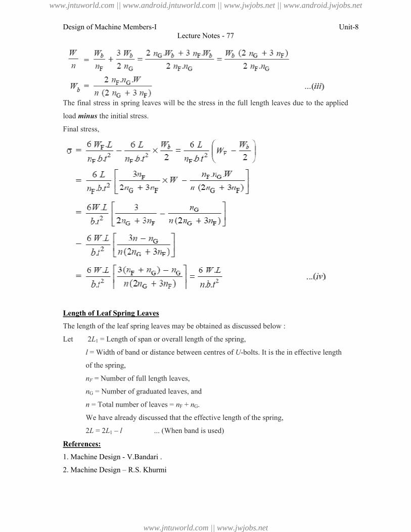
Design of Machine Members-I
The final stress in spring leaves will be the stress in the full length
load minus the initial stress.
Final stress,
Length of Leaf Spring Leaves
The length of the leaf spring leaves may be obtained as discussed below :
Let 2L1 = Length of span or overall length of the spring,
l = Width of band or distance between centres of
of the spring,
nF = Number of full length leaves,
nG = Number of graduated leaves, and
n = Total number of leaves =
We have already discussed that the effective length of the
2L = 2L1 – l ... (
References:
1. Machine Design - V.Bandari .
2. Machine Design – R.S. Khurmi
Lecture Notes - 77
The final stress in spring leaves will be the stress in the full length leaves due to the applied
The length of the leaf spring leaves may be obtained as discussed below :
= Length of span or overall length of the spring,
distance between centres of U-bolts. It is the in effective length
= Number of full length leaves,
= Number of graduated leaves, and
= Total number of leaves = nF + nG.
We have already discussed that the effective length of the spring,
... (When band is used)
V.Bandari .
R.S. Khurmi
Unit-8
leaves due to the applied
effective length
www.jntuworld.com || www.android.jntuworld.com || www.jwjobs.net || www.android.jwjobs.net
www.jntuworld.com || www.jwjobs.net

Design of Machine Members-I Unit-8Lecture Notes - 77
3. Design Data hand Book - S MD Jalaludin.
www.jntuworld.com || www.android.jntuworld.com || www.jwjobs.net || www.android.jwjobs.net
www.jntuworld.com || www.jwjobs.net
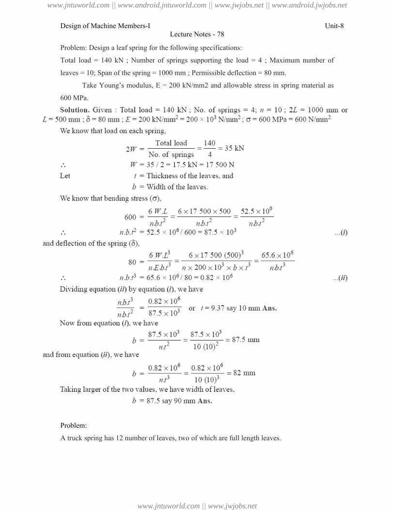
Design of Machine Members-I
Problem: Design a leaf spring for the following specifications:
Total load = 140 kN ; Number of springs supporting the load = 4 ; Maximum number of
leaves = 10; Span of the spring = 1000 mm ; Permissible deflection = 80 mm
Take Young’s modulus, E = 200 kN/mm2
600 MPa.
Problem:
A truck spring has 12 number of leaves, two of which are full length leaves.
Lecture Notes - 78
Problem: Design a leaf spring for the following specifications:
Total load = 140 kN ; Number of springs supporting the load = 4 ; Maximum number of
= 10; Span of the spring = 1000 mm ; Permissible deflection = 80 mm.
Take Young’s modulus, E = 200 kN/mm2 and allowable stress in spring
A truck spring has 12 number of leaves, two of which are full length leaves.
Unit-8
Total load = 140 kN ; Number of springs supporting the load = 4 ; Maximum number of
and allowable stress in spring material as
www.jntuworld.com || www.android.jntuworld.com || www.jwjobs.net || www.android.jwjobs.net
www.jntuworld.com || www.jwjobs.net
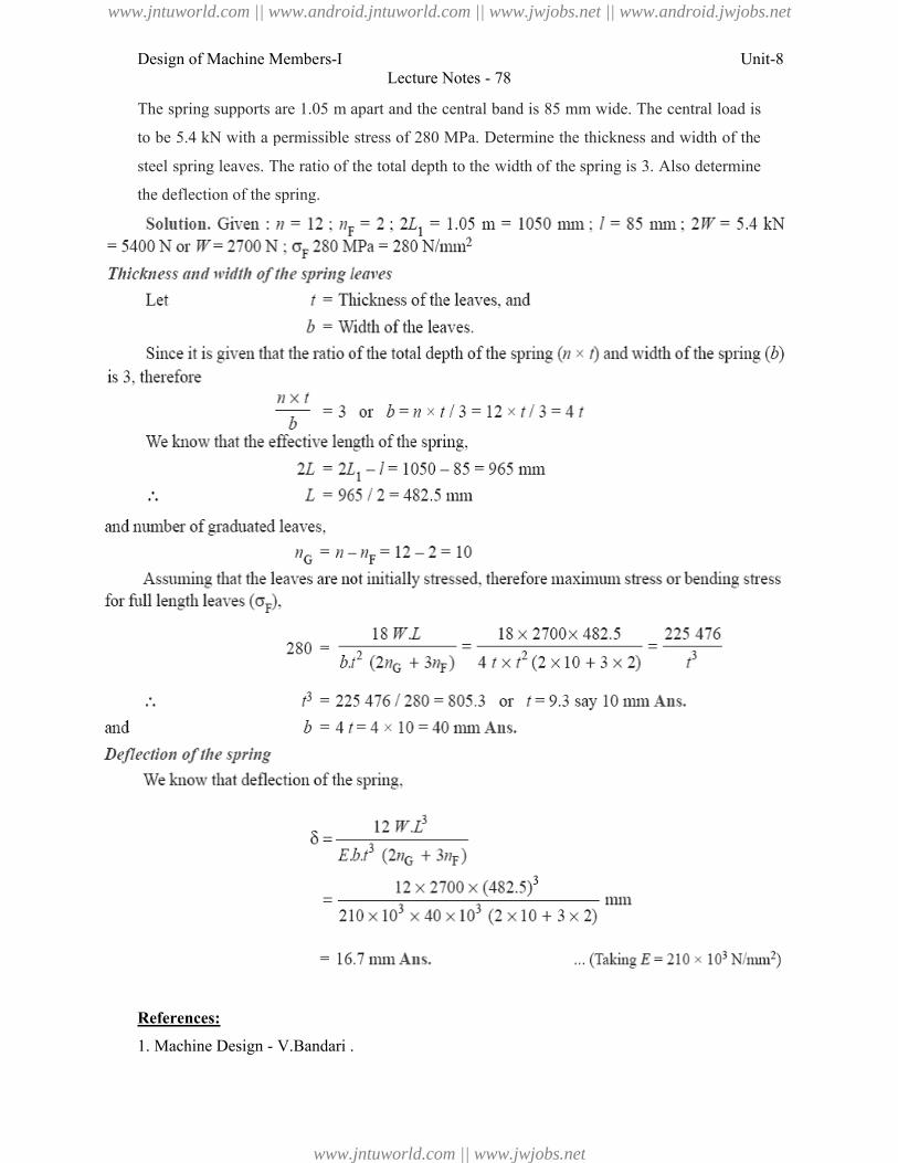
Design of Machine Members-I
The spring supports are 1.05 m apart and the central band is 85 mm wide. The
to be 5.4 kN with a permissible stress of 280 MPa. Determine the thickness and width of the
steel spring leaves. The ratio of the total depth to the width of the spring is 3. Also determine
the deflection of the spring.
References:
1. Machine Design - V.Bandari .
Lecture Notes - 78
The spring supports are 1.05 m apart and the central band is 85 mm wide. The central load is
5.4 kN with a permissible stress of 280 MPa. Determine the thickness and width of the
leaves. The ratio of the total depth to the width of the spring is 3. Also determine
V.Bandari .
Unit-8
central load is
5.4 kN with a permissible stress of 280 MPa. Determine the thickness and width of the
leaves. The ratio of the total depth to the width of the spring is 3. Also determine
www.jntuworld.com || www.android.jntuworld.com || www.jwjobs.net || www.android.jwjobs.net
www.jntuworld.com || www.jwjobs.net

Design of Machine Members-I Unit-8Lecture Notes - 78
2. Machine Design – R.S. Khurmi
3. Design Data hand Book - S MD Jalaludin.
www.jntuworld.com || www.android.jntuworld.com || www.jwjobs.net || www.android.jwjobs.net
www.jntuworld.com || www.jwjobs.net