Embed Size (px)
Citation preview
Module 4 EE 100 Basics of Electrical Engineering
Page 1 of 12 Dept. of EEE, SNGIST
HYDRO POWER PLANT
A generating station which utilizes the potential energy of water at a high level for the generation
of electrical energy is known as a hydro-electric power station.
Hydro-electric power stations are generally located in hilly areas where dams can be built
conveniently and large water reservoirs can be obtained. In a hydro-electric power station, water
head is created by constructing a dam across a river or lake. From the dam, water is led to a water
turbine. The water turbine captures the energy in the falling water and changes the hydraulic energy
(i.e., product of head and flow of water) into mechanical energy at the turbine shaft. The turbine
drives the alternator which converts mechanical energy into electrical energy.
Advantages
It requires no fuel as water is used for the generation of electrical energy.
It is quite neat and clean as no smoke or ash is produced.
It requires very small running charges because water is available free of cost.
It is comparatively simple in construction and requires less maintenance.
It is robust and has a longer life. In addition to the generation of electrical energy, they
also help in irrigation and controlling floods.
Although such plants require the attention of highly skilled persons at the time of
construction, yet for operation, a few experienced persons may do the job well.
Disadvantages
It involves high capital cost due to construction of dam.
There is uncertainty about the availability of huge amount of water due to dependence on
weather conditions.
Skilled and experienced hands are required to build the plant.
It requires high cost of transmission lines as the plant is located in hilly areas which are
quite away from the consumers.
Module 4 EE 100 Basics of Electrical Engineering
Page 2 of 12 Dept. of EEE, SNGIST
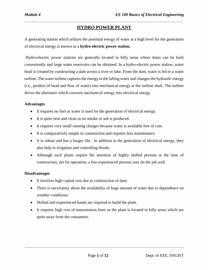
SCHEMATIC ARRANGEMENT OF HYDRO-ELECTRIC POWER STATION
Dam: A dam is a barrier which stores water and creates water head. Dams are built of concrete or
stone masonry, earth or rock fill
Surge Tank: The penstock pipes are provided with valves for controlling the water flow. When
these valves are closed or opened, there will be an abnormal pressure variation inside the penstock.
This abnormal pressure variations may damage the penstock. To protect the penstock surge tank
is used. A surge tank is a small reservoir or tank in which water level rises or falls to reduce the
pressure swings in the penstock.
Valve House: It contains valves to regulate water flowing through the penstock
Penstocks: Penstocks are open or closed conduits which carry water to the turbines. They are
generally made of reinforced concrete or steel.
Turbine: Water turbines are used to convert the energy of falling water into mechanical energy.
The turbine is coupled to the generator and drives the generator.
Generator: It converts mechanical energy to electrical energy
Module 4 EE 100 Basics of Electrical Engineering
Page 3 of 12 Dept. of EEE, SNGIST
NUCLEAR POWER PLANT
In nuclear power plant, the energy released during the nuclear fission reaction is used to generate
electricity. The Uranium-235 is used as fuel, and the enormous heat energy released during the
fission reaction is used to generate steam. This steam is fed to the turbine which drives the
generator, thus producing electricity.
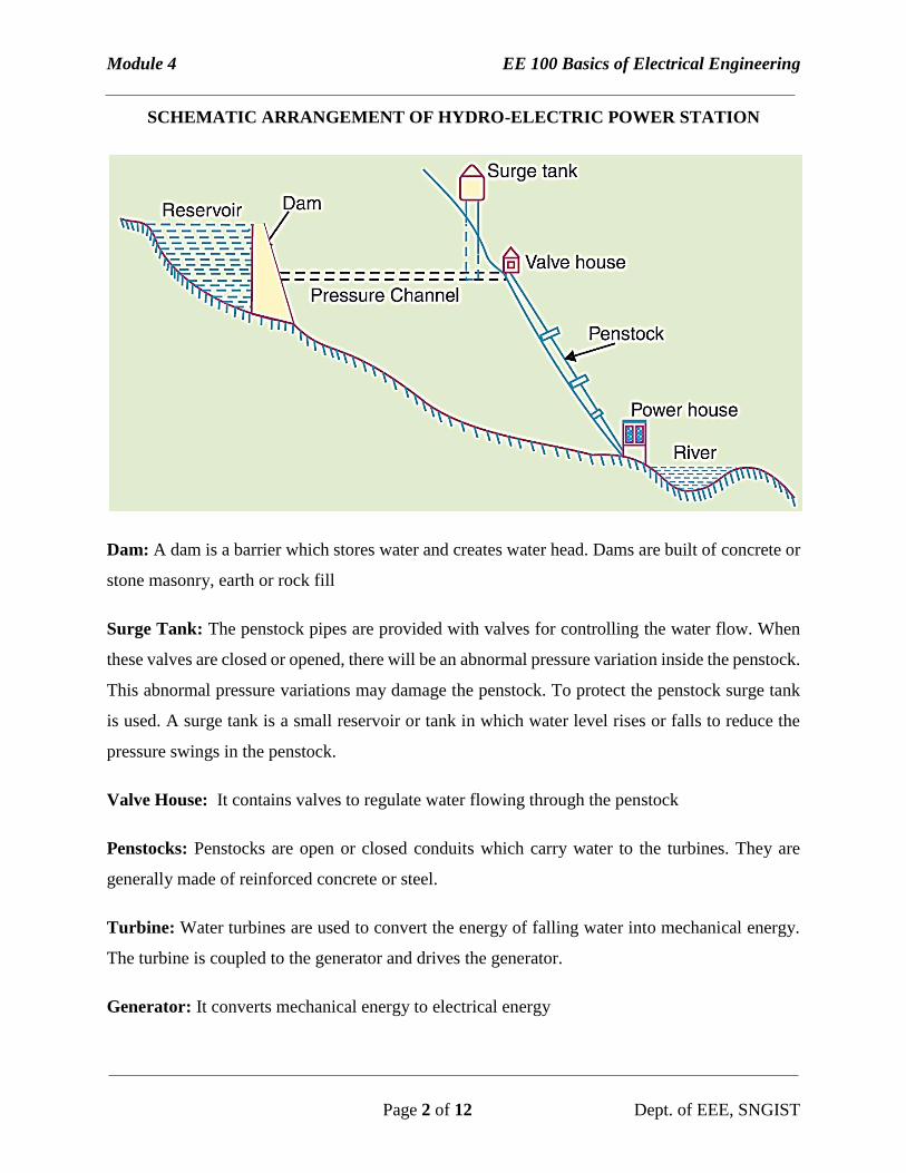
BLOCK DIAGRAM OF NUCLEAR POWER PLANT
Nuclear Reactor : Reactor is that part of nuclear power plant where nuclear fuel is subjected to
nuclear fission and the energy released in the process is utilised to heat the molten metal. The
reactor consist of Fuel rods, control rods and moderator.
Heat Exchanger: In heat exchanger, the heat of molten metal is transferred to water and produce
steam.
Turbine: Turbines convert the energy of steam hitting the blade into mechanical energy. The
turbine is coupled to the generator and drives the generator.
Generator – It converts mechanical energy to electrical energy.
Condenser – It condenses steam and turns it back to water.
Module 4 EE 100 Basics of Electrical Engineering
Page 4 of 12 Dept. of EEE, SNGIST
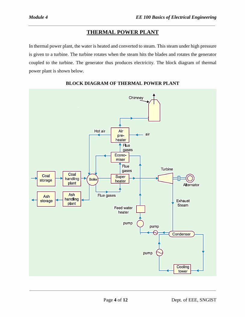
THERMAL POWER PLANT
In thermal power plant, the water is heated and converted to steam. This steam under high pressure
is given to a turbine. The turbine rotates when the steam hits the blades and rotates the generator
coupled to the turbine. The generator thus produces electricity. The block diagram of thermal
power plant is shown below.
BLOCK DIAGRAM OF THERMAL POWER PLANT
Module 4 EE 100 Basics of Electrical Engineering
Page 5 of 12 Dept. of EEE, SNGIST
Coal Storage and Coal Handling Plant : The coal storage stores the coal. The coal handling
plant crushes the coal to powder. The pulverised coal is the fed to boiler for burning.
Ash Storage and Ash Handling Plant : The burning coal produces ash inside the boiler. This ash
needs to be periodically removed. This is done by ash handling plant and the ash is then stored for
proper disposal.
Boiler : The coal is burned in the boiler and the water inside the boiler turns to steam. The steam
is then fed to turbine through super heater. The exhaust gas (flue gas) is then passed to chimney
through superheater, economizer and air preheater.
Super heater : The superheater takes the heat from exhaust gas and heats the steam once again to
high temperature before passing to turbine.
Economizer : The economizer takes the heat from exhaust gas and heats the water before entering
the boiler. This increases the efficiency of the plant.
Air Preheater : The air preheater takes the heat from exhaust gas and heats the air before entering
the boiler. This increases the efficiency of the plant.
Turbine and Generator : The turbine and generator are coupled together. When the steam hits
the blades of the turbine, the turbine starts rotating. This in turn rotates the generator and produces
electricity.
Condenser and Cooling Tower : This arrangement is for cooling the steam coming out of turbine.
The steam is condensed to water and fed to boiler through economizer.
Module 4 EE 100 Basics of Electrical Engineering
Page 6 of 12 Dept. of EEE, SNGIST
RENEWABLE ENERGY
The most common forms of renewable energies are Solar Energy, Wind Energy, Tidal Energy and
Geothermal Energy.
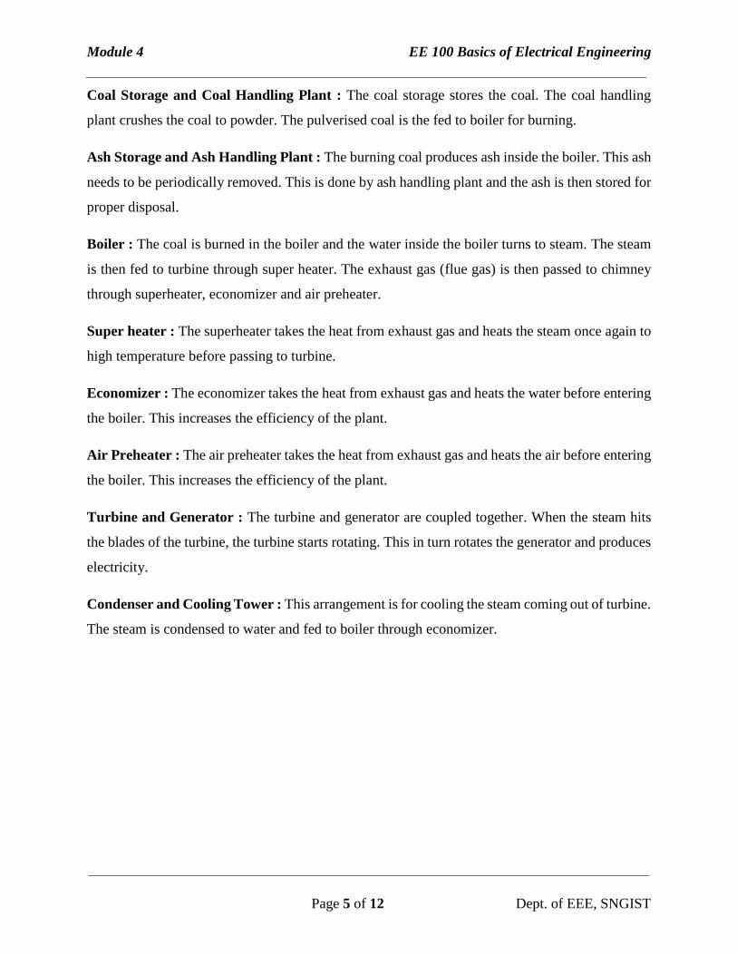
SOLAR ENERGY
In solar energy, the sunlight is converted to electricity by photovoltaic effect. The device which
convert sunlight to electricity is called solar panel.
Solar Panel : It converts sunlight to electricity. The output of solar panel is DC.
Power Converter : It is used to increase the DC voltage. It also controls the charging of battery.
Battery : It is used to store electricity. The stored electricity is utilized when sunlight is not
sufficient to produce electricity i.e during night and cloudy days.
Inverter : It converts DC to AC and supplies the load.
Power Converter
Solar Panel
Module 4 EE 100 Basics of Electrical Engineering
Page 7 of 12 Dept. of EEE, SNGIST
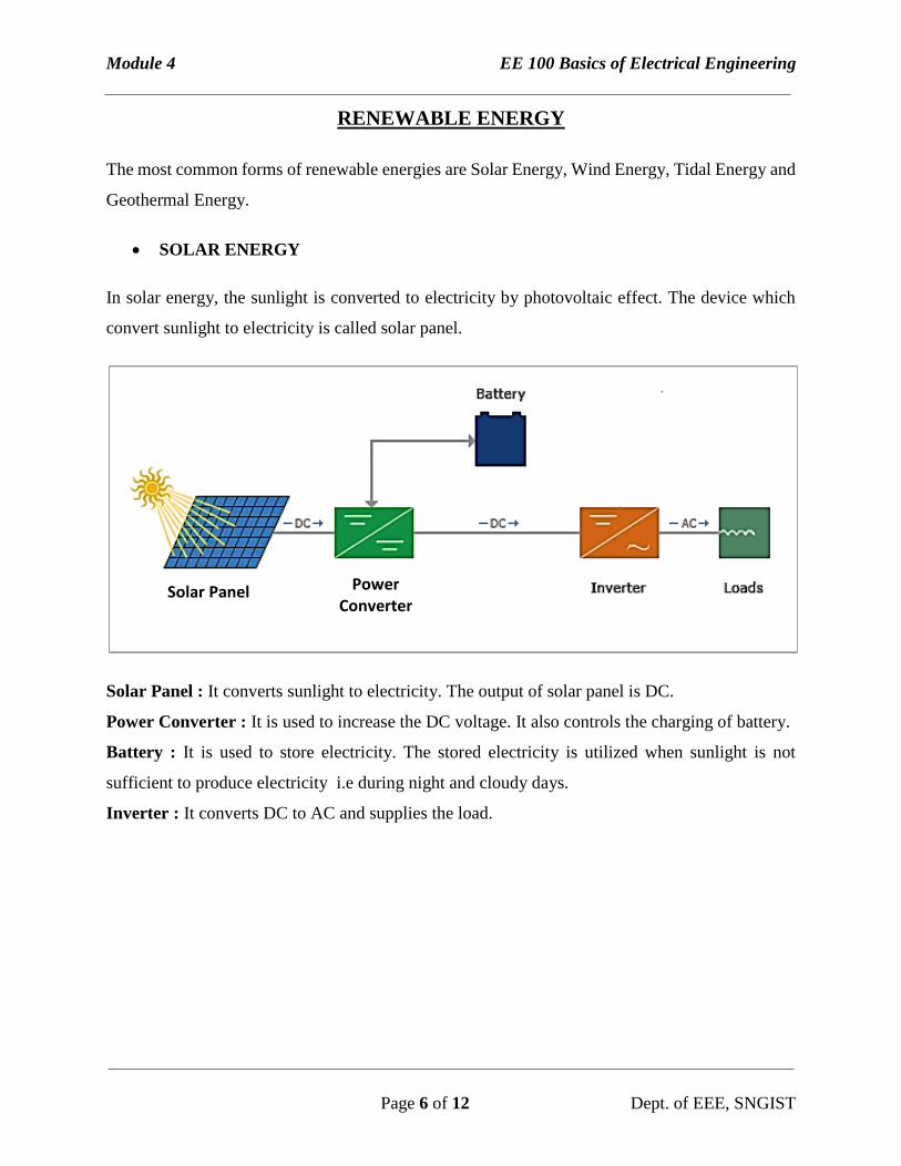
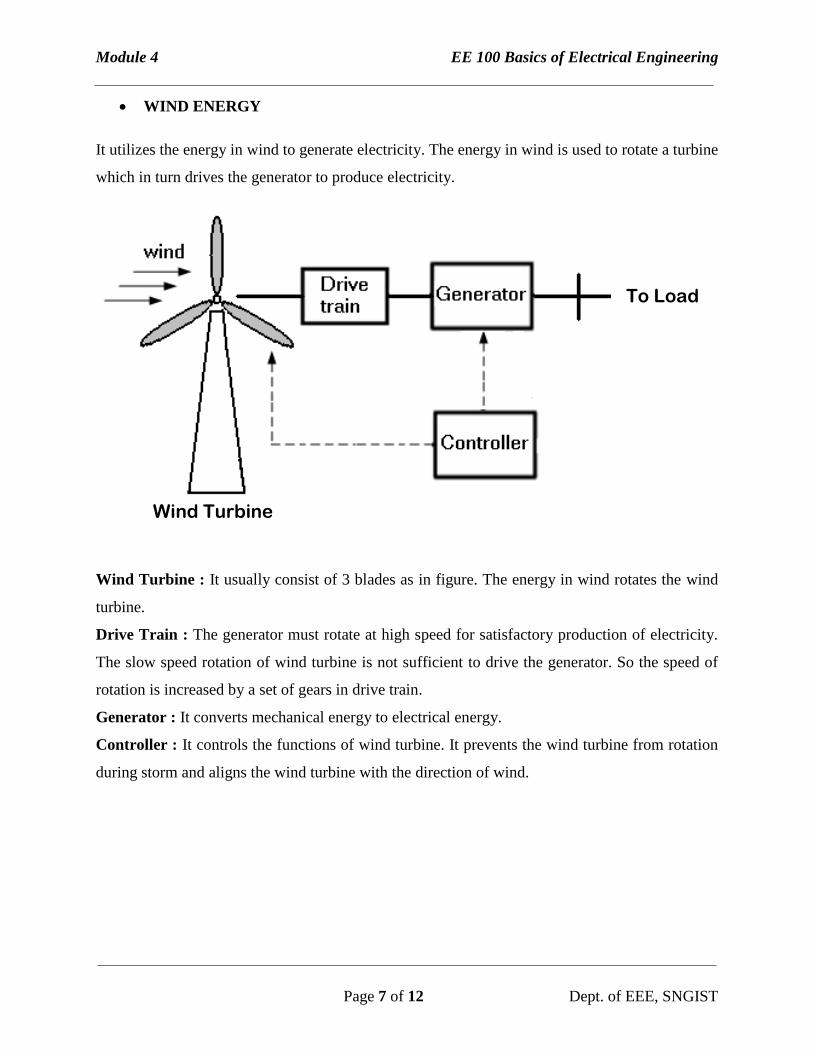
WIND ENERGY
It utilizes the energy in wind to generate electricity. The energy in wind is used to rotate a turbine
which in turn drives the generator to produce electricity.
Wind Turbine : It usually consist of 3 blades as in figure. The energy in wind rotates the wind
turbine.
Drive Train : The generator must rotate at high speed for satisfactory production of electricity.
The slow speed rotation of wind turbine is not sufficient to drive the generator. So the speed of
rotation is increased by a set of gears in drive train.
Generator : It converts mechanical energy to electrical energy.
Controller : It controls the functions of wind turbine. It prevents the wind turbine from rotation
during storm and aligns the wind turbine with the direction of wind.
To Load
Wind Turbine
Module 4 EE 100 Basics of Electrical Engineering
Page 8 of 12 Dept. of EEE, SNGIST
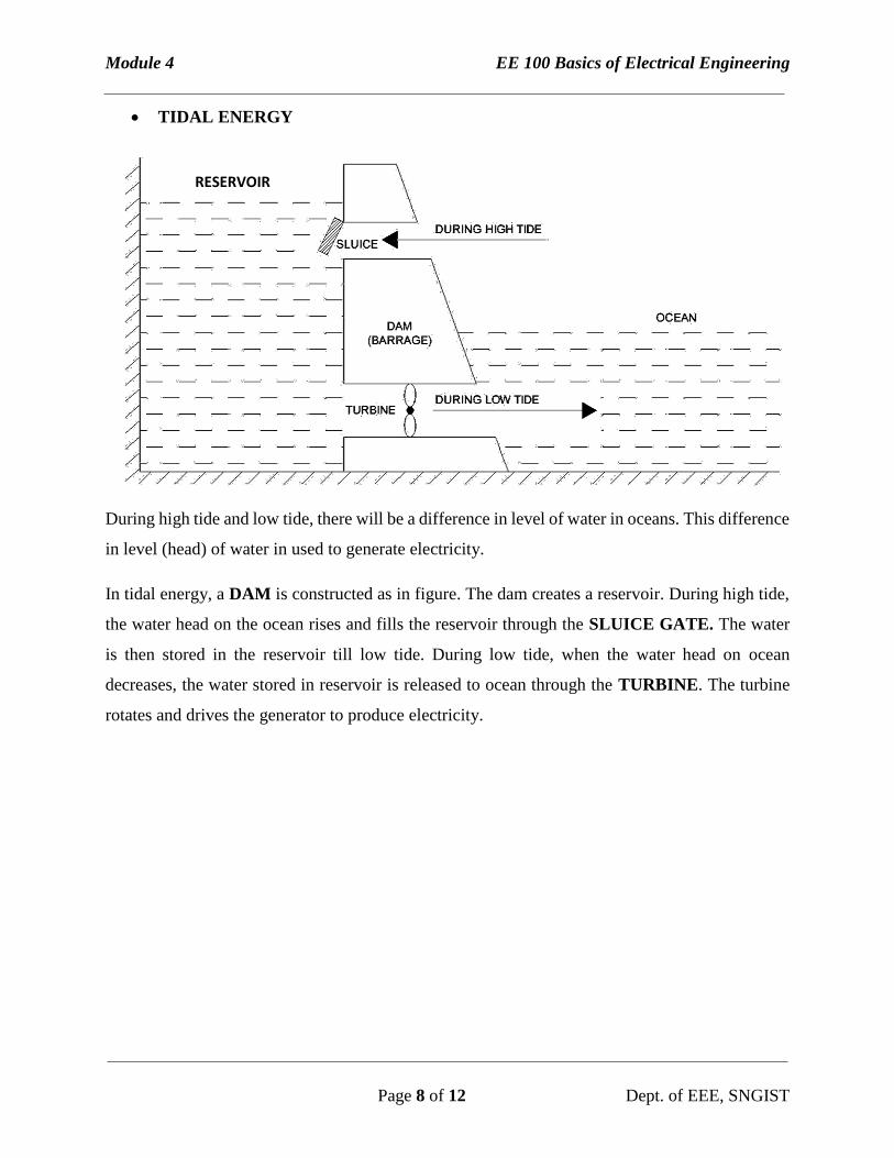
TIDAL ENERGY
During high tide and low tide, there will be a difference in level of water in oceans. This difference
in level (head) of water in used to generate electricity.
In tidal energy, a DAM is constructed as in figure. The dam creates a reservoir. During high tide,
the water head on the ocean rises and fills the reservoir through the SLUICE GATE. The water
is then stored in the reservoir till low tide. During low tide, when the water head on ocean
decreases, the water stored in reservoir is released to ocean through the TURBINE. The turbine
rotates and drives the generator to produce electricity.
RESERVOIR
Module 4 EE 100 Basics of Electrical Engineering
Page 9 of 12 Dept. of EEE, SNGIST
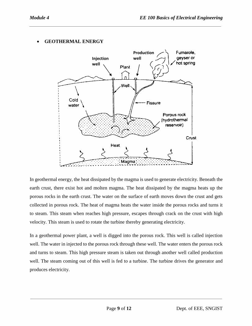
GEOTHERMAL ENERGY
In geothermal energy, the heat dissipated by the magma is used to generate electricity. Beneath the
earth crust, there exist hot and molten magma. The heat dissipated by the magma heats up the
porous rocks in the earth crust. The water on the surface of earth moves down the crust and gets
collected in porous rock. The heat of magma heats the water inside the porous rocks and turns it
to steam. This steam when reaches high pressure, escapes through crack on the crust with high
velocity. This steam is used to rotate the turbine thereby generating electricity.
In a geothermal power plant, a well is digged into the porous rock. This well is called injection
well. The water in injected to the porous rock through these well. The water enters the porous rock
and turns to steam. This high pressure steam is taken out through another well called production
well. The steam coming out of this well is fed to a turbine. The turbine drives the generator and
produces electricity.
Injection well
Production well
Module 4 EE 100 Basics of Electrical Engineering
Page 10 of 12 Dept. of EEE, SNGIST
NEED FOR HIGH TRANSMISSION VOLTAGE
For transmitting electric power over long distance, it is more economical to choose very high
transmission voltage (eg. 110 kV, 132 kV, 220 kV, 400 kV…). By transmitting electric power at
high voltage, we can reduce the losses and increase the efficiency of transmission.
For a given amount of power,
P = V.I.cos θ
i.e I = P
Vcosθ (1)
Here the power P is constant and power factor cos θ is constant. So as per the above equation (1),
the current will be reduced if the value of voltage is increased.
So by reducing current we have the following advantages
The I2R loss is reduced.
The voltage drop in the transmission line is reduced.
The voltage regulation of transmission line in improved.
Increased efficiency.
Since the current is reduced, the size of transmission line is reduced.
SCHEME OF ELECTRICAL POWER SYSTEM
The electrical power system is divided into 3 segments : Generation, Transmission and
Distribution.
Generation : The generation of electricity is done in power plants. The power plant produces bulk
amount of power at 11 kV or 11,000 Volts. These power plants are situated away from cities. This
generated power is to be transmitted over long distance for delivering to the customer.
Module 4 EE 100 Basics of Electrical Engineering
Page 11 of 12 Dept. of EEE, SNGIST
Transmission : The generated power is transmitted over long distance by means of large towers
and lengthy conductors. Before transmitting the generated voltage (11 kV) is increased (stepped
up) to high voltage (110 kV, 132 kV, 220 kV, 400 kV…). When the transmission line reaches the
cities the transmission voltage is stepped down to 66 kV or 33 kV.
The transmission at voltages (110 kV, 132 kV, 220 kV, 400 kV…) are called primary transmission.
The transmission at voltages (66 kV or 33 kV…) are called secondary transmission.
Distribution : The transmitted voltage, when it reached the cities, it is again stepped down to
11kV and distributed to large consumers or feed several areas. This is called primary distribution.
For small consumers, the 11kV is again stepped down to 415V and supplied to each consumer.
This is called secondary distribution.
SUBSTATION
Substation : “The assembly of apparatus used to change some characteristic (e.g. voltage, a.c. to
d.c., frequency, p.f. etc.) of electric supply”
CLASSIFICATION OF SUBSTATION
The substations are classified according to service requirement as :
Transformer sub-stations : For stepping up and stepping down voltage during
transmission or distribution.
Switching sub-stations : For switching purpose only.
Power factor correction sub-stations : Here the power factor of the power system is
changed. The voltage and current remains same.
Frequency changer sub-stations : Here the frequency of the supply is changed. The
voltage and current remains same.
Converting sub-stations : Perform the function of power conversion. i.e conversion from
AC to DC and from DC to AC.
Industrial sub-stations : Provides power only to a specific industry only. There will be
no supply of power to public consumers.
Module 4 EE 100 Basics of Electrical Engineering
Page 12 of 12 Dept. of EEE, SNGIST
The substations are classified according to type of construction as :
Indoor sub-station
Outdoor sub-station
Underground sub-station
Pole-mounted sub-station
SUBSTATION EQUIPMENTS
BUS-BARS – These are copper or aluminium bars used as conductors to carry current.
INSULATORS – To support the conductor to and to provide protection for electric shock
and current leakage
ISOLATING SWITCHES – These are switches which are used to disconnect a part or a
device from service for maintenance and repair
CIRCUIT BREAKER – A device used for protection from short circuit and other faults.
POWER TRANSFORMER – For step up/down of supply voltage.
CURRENT TRANSFORMER (CT) – It is a step up transformer used to measure current.
It steps down current to a low value which is easy for measurement.
POTENTIAL TRANSFORMER (PT) – It is a step down transformer used for measuring
voltage.
METERING AND INDICATING INSTRUMENTS :- These include ammeter, voltmeter,
energy meter etc used for measuring various parameters and indication lamps for indicating
several signals.