Embed Size (px)
Citation preview
GSM SYSTEM ARCHITECTURE AND INTERFACES
SYSTEM ARCHITECTURE
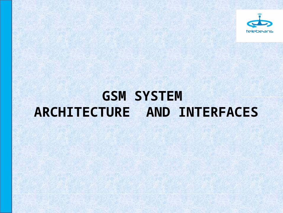
The network is divided into three major systems:· Switching System (SS)· Base Station System (BSS)· Operation and Support System (OSS)
SS is responsible for performing call processing and subscriber related functions. It includes the following functional units:
• Mobile services Switching Center (MSC)• Home Location Register (HLR)• Visitor Location Register (VLR)• Authentication Center (AUC)• Equipment Identity Register (EIR)• Flexible Numbering Register (FNR)
Most radio related functions are performed in the Base Station System (BSS). BSS includes:
• Base Station Controller (BSC)• Transcoder Controller (TRC)• Radio Base Station (RBS) The Operation and Support System (OSS) handles error
messages originating from the network. OSS has access to both the switching system and the base station system (via BSC).
SWITCHING SYSTEM
• Functions for setting up and controlling calls, including supplementary services.
• Functions for handling speech path continuity for moving subscribers (handover).
• Functions for updating mobile subscribers’ location (location updating and location canceling) in the different location registers.
• Administrative functions for defining data and handling of the mobile subscribers.
• Functions for IMEI check.• Charging and accounting.
Visitor Location Register
The Visitor Location Register (VLR) is a database containinginformation about all MSs that currently are located in the MSCservice area. The VLR contains temporary subscriberinformation needed by the MSC to provide service for visitingsubscribers. The VLR can be seen as a distributed HLR. When aMobile Station (MS) roams into a new MSC service area, theVLR connected to that MSC requests data about the MS fromthe HLR and stores it. When the MS makes a call, the VLRalready has the information needed for call set-up. In Ericsson’sGSM system, the VLR is always integrated with the MSC sothat internal signaling can be used..
Gateway MSC
The Gateway MSC (GMSC) is the point in the PLMN where calls to mobile subscribers enter the GSM network. Therefore each mobile terminating call must be routed via a GMSC in the home PLMN of the called MS. The GMSC contains the interrogation facility. That is, the GMSC contains signaling functions for retrieving information from the concerned HLR, which tells how to proceed with call Set-up.
Depending on the interrogation result, the call is either re-routed by GMSC to the MSC where the mobile subscriber is located or forwarded according to the forward-to number. Charging and accounting functions are also implemented in the GMSC.
Interworking Unit
The Interworking Unit (IWU) provides an interface to variousnetworks for data communication. At present Ericssonimplements this functionality in the Data TransmissionInterworking unit (DTI) through which users can alternate between speech and data during the same call. Its main functions include modem and fax adapter pool plus the node
has the ability to perform rate adaptation. This was earlierimplemented as the GSM Inter Working Unit (GIWU). Both DTIand GIWU consist of software and hardware.
Short Message Service - Gateway MSC
A Short Message Service Gateway MSC (SMS-GMSC) is capable of receiving a short message from a Service Center (SC), interrogating an HLR for routing information and message waiting data, and delivering the short message to the MSC of the receiving MS. In Ericsson’s GSM system, the SMS-GMSC functionality is normally integrated in the MSC/VLR node.
Short Message Service - Interworking MSC
A Short Message Service Inter Working MSC (SMS-IWMSC) is capable of receiving a mobile originated short message from the MSC or an Alert message from the HLR and submitting the message to the sender's SC. The SMS-IWMSC functionality is normally integrated in the MSC/VLR node.
Home Location Register
• The associated numbers - MSISDN and IMSI• A list of services – tele services, bearer services and supplementary
services, which the subscriber is authorized to use.• Connection of mobile subscribers and definition of corresponding
subscriber data.• Maintenance of a database of mobile subscribers and corresponding
subscriber data.• Subscription to basic services.• Registration/deletion of supplementary services.• Activation/deactivation of supplementary services.• Interrogation of supplementary services status.• Handling of authentication and ciphering data for mobile subscribers
including communication with an authentication center.
Authentication Center
The Authentication Center (AUC) is a database that stores the following data:
• A RANDom number (RAND)• A Signed RESponse (SRES)• A Ciphering Key (Kc) These three pieces of data are called triplets. The AUC generates and
provides one several triplets for a certain IMSI at each request from the HLR. The HLR forwards the provided triplets to the serving VLR. At any MS access attempt, the MSC may send RAND to the MS to authenticate the subscriber’s SIM.
The SRES returned by the MS is then compared to the SRES provided by the AUC (via HLR) to the VLR. The MSC may also facilitate ciphering on the radio path by providing the TRX managing the traffic with the Kc. Successful ciphering is possible only if the Kc, which is calculated by the MS during the authentication procedure, is identical to the one provided to the TRX.
Equipment Identity Register
The Equipment Identity Register (EIR) is a database that stores the International Mobile station Equipment Identity (IMEI) for
each MS equipment. The main objective is to ensure• that the equipment is not stolen or faulty. Equipment can be
classified as:• white listed (permitted for use)• gray listed (should be tracked for evaluation)• black listed (barred)• unknown equipment
Flexible Numbering Register
The Flexible Numbering Register is an optional node used when the Flexible Numbering feature or the Number Portability feature are used in the network.
With the Flexible Numbering it is possible to have no relation between a MSISDN number series and a certain HLR in the network. Messages sent from an GMSC towards an HLR regarding a certain MSISDN are routed through the FNR which redirects the messages to the HLR storing data about this particular subscriber.
Interworking Location Register
Interworking Location Register (ILR) is a product that exists in the CMS 40 network only. ILR makes inter-system roaming possible. This means that roaming between an AMPS network and a GSM 1900 network is possible. ILR consists of an AMPS HLR and parts of a GSM 1900 VLR
BASE STATION SYSTEM
The Base Station System (BSS) consists of the BSC and the BTS.
Base Station Controller
The Base Station Controller (BSC) handles most radio-related functions and is the BSS's center point. The BSC manages the entire radio network including:
• Configuration of the network.• Administration and remote control of the RBSs.• Handling connections to MSs including handovers.• The large BSCs can handle up to 1020 transceivers (TRXs). The smaller combined MSC/BSC is designed for recently started mobile
operating companies.• During call set up, a logical channel is allocated to the connection based
on information about the available channels’ characteristics. When the connection has been established, signal strength and speech quality are monitored by the MS and the TRX or TRU (Transceiver Unit, appears instead of the TRX in RBS 2000) and reports are forwarded to the BSC.
Transcoder Controller
The BSC product family consists of a combined BSC/TRC, a remote BSC (without transcoders) and a standalone Transcoder Controller (TRC). The Transcoder Controller contains a set of transcoders for speech coding/decoding purposes. It also performs rate adaptation for data connections. The transcoders are pooled, meaning that they can be allocated on demand – Full Rate, Half Rate or
Enhanced Full Rate.
Base Transceiver Station / Radio Base Station
The main RBS functions are:• Radio transmission, including frequency hopping• Radio signal reception from MSs, including equalizing and
diversity functions to compensate for fading effects.• Time alignment measurements.• Transceiver and MS power control• Multiplexing on the radio path, channel coding, interleaving,
and ciphering.• Broadcasting system information and paging messages.• Receiving channel requests from MSs
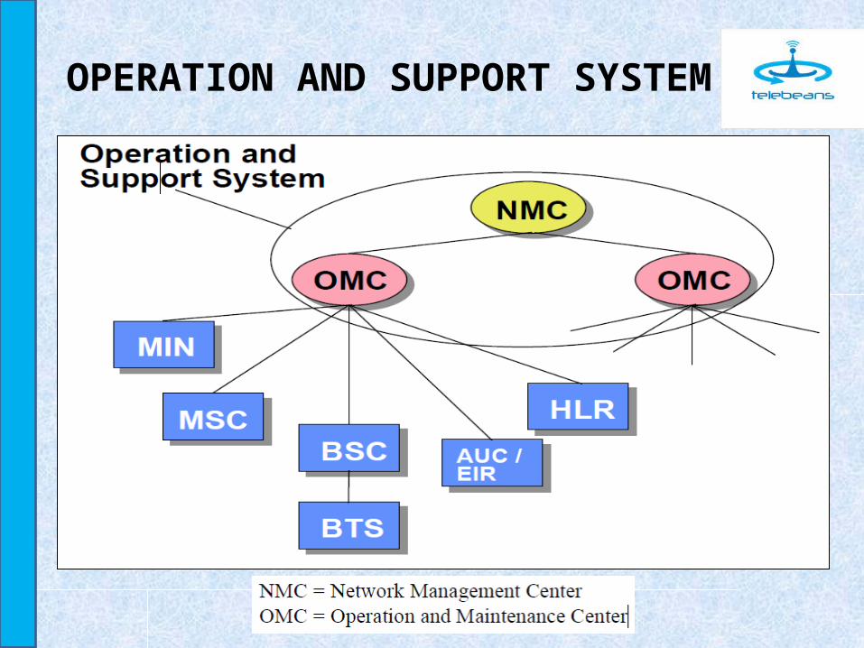
OPERATION AND SUPPORT SYSTEM
OPERATION AND SUPPORT SYSTEM
OSS management areas are based on Telecommunication Management Network (TMN), which is a model for telecommunication networks management. The most important parts are:
• Configuration management• Fault management• Performance management
GSM PROTOCOLS AND INTERFACES
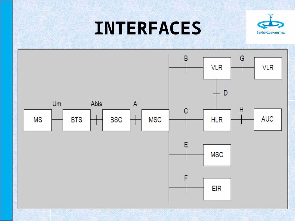
INTERFACES The interface between MSC and BSS is called the A interface,
the interface between MSC and VLR the B interface, and the other interfaces .
The A interface is divided into two parts:• The A interface between MSC and BSC• The A-bis interface between BSC and BTS The air interface between MS and BTS is called the Um
interface.
INTERFACES

THANKS


![Interfaces GSM[WwW.VosBooks.NeT].pdf](https://img.pdfslide.net/doc/110x75/55cf9d87550346d033ae054c/interfaces-gsmwwwvosbooksnetpdf.jpg)