Embed Size (px)
Citation preview

Learning Optics using Vision
Anjul MaheshwariDavid R. Williams
Biomedical EngineeringCenter for Visual ScienceUniversity of Rochester
Rochester, NYCenter for Adaptive Optics
Project #42
2
INTRODUCTION
Of the five senses, humans heavily depend on sight. Not until it is taken away
from us, even temporarily, do we truly appreciate the amazing biological system of the
eye. Our visual system allows us to walk down a path in the middle of the night,
determine which snakes are dangerous by its markings, and gauge the distance between
you and a wild bear. We are able to differentiate between colors, textures, sizes, and
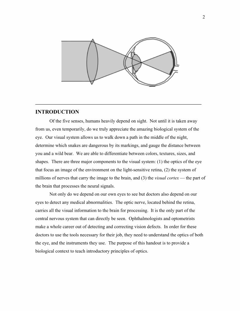
shapes. There are three major components to the visual system: (1) the optics of the eye
that focus an image of the environment on the light-sensitive retina, (2) the system of
millions of nerves that carry the image to the brain, and (3) the visual cortex — the part of
the brain that processes the neural signals.
Not only do we depend on our own eyes to see but doctors also depend on our
eyes to detect any medical abnormalities. The optic nerve, located behind the retina,
carries all the visual information to the brain for processing. It is the only part of the
central nervous system that can directly be seen. Ophthalmologists and optometrists
make a whole career out of detecting and correcting vision defects. In order for these
doctors to use the tools necessary for their job, they need to understand the optics of both
the eye, and the instruments they use. The purpose of this handout is to provide a
biological context to teach introductory principles of optics.

3
ANATOMY OF THE EYE
Since the times of ancient Greece, people have tried to uncover the mystery of
vision. Ancient Grecians believed that sight entailed tentacles or threads emitted from
the eye and physically touched the objects they saw. Through centuries of discoveries
and the advancement of technology we have progressed towards a deep understanding
about vision. However in centuries to come we will probably understand things about
vision that we do not even questioned today.
There are several similarities between the human eye and a photographic camera
(Figure 1). A camera is a light-sealed box with a lens system for forming images onto
light-sensitive film. A stop and shutter are used to control the amount of light that enters
the box. The eye is also a light-sealed box with a two-lens system consisting of a cornea
and crystalline lens. The lens system of the eye forms inverted images onto a light-
sensitive film, the retina. Lastly, the pupil of the eye controls the amount of light that
enters. Our optical system, however have some special features that not even the most
expensive cameras have:
1) Eye can observe events over a large angle while concentrating on an object
directly ahead of it.
2) Blinking provides a built-in lens cleaner and lubricator.
3) The eye has a rapid auto-focus system called accommodation. It can quickly
focus from an object only 20 cm away to one far away in the distance. A relaxed
eye is focused for an object at infinity (distant viewing).
Figure 1 The eye is optically similar to a camera. (a) Human eye. (b) Camera

4
4) The eye can adapt to light ranges of almost a billion to one (1010:1), bright
daylight to very dark night.
5) The eye has an automatic aperture adjustment (the iris) to control the pupil size.
6) The cornea had a built-in scratch remover. The cornea is made of living cells that
can repair local damage.
7) The image appears inverted or upside down, on the retina, but the visual cortex
automatically corrects for this.
8) The visual cortex blends the images from both eyes, giving us good depth
perception and three-dimensional viewing. Even if vision is lost in one eye, the
vision from the healthy eye is sufficient for normal day-to-day function.
FOCUSING BY THE EYE
There are two main focusing elements of the eye: the cornea that is responsible
for two-thirds of the focusing, and the crystalline lens, which does the fine focusing. To
understand how an image is formed on the retina we need to examine the optical
properties of lenses and image formation.
Refraction
Light travels through air at a velocity of approximately sm8100.3 × . When traveling
through mediums such as transparent solids (i.e. glass) or liquids, light travels at a slower
speed. The ratio of the velocity of light in air to the velocity in a medium is known as the
refractive index and is usually denoted by an n. The refractive index for air is 1.00.
Example
Determine the refractive index for a type of glass that slows the velocity of
light to sm8100.2 × .
Solution By calculating the ratio of the velocity of light traveling
through air to the velocity of light traveling through the glass we find that

5
50.1
100.2
100.38
8
=××=
g
g
n
sm
smn
The index of refraction for the glass is 1.50.
When light travels from one medium to a medium with a different refractive
index, it will deviate from its original linear path. The bending of light caused by a
refractive index mismatch is called refraction. The relationship between two mediums
and the angle of refraction, as illustrated in Figure 2 is known as Snell s Law and looks
like this:
2211 sinsin θθ nn =
The cornea refracts incident light rays to a focus on the retina. The refractive
index of the cornea and other optical parts of the eye are listed in (Table 1). The
refractive index of the cornea is near that of water (n= 1.33). This is why when you open
your eyes underwater things are not as focused as above water. The index mismatch
between water and the cornea is not large enough to refract the light rays to a focus on the
retina. If you wore goggles, your vision under water would be normal because you
restored the air to cornea interface. As you can see, the indexes of refraction for the
interior components of the eye are similar to each other. Once the light enters the eye,
very little refraction occurs.
Part of the Eye Index of Refraction
Cornea 1.34
Aqueous humor 1.33
Lens cover 1.38
Lens center 1.41
Vitreous humor 1.34
Table 1 Indexes of refraction of optical partsof the eye.
Figure 2 Illustration of Snell’s lawwhere n1 < n2.

6
Lenses
Lenses are usually made of glass or plastic and are used to refract light rays in a
desired direction. When parallel light passes through a convex lens the beams converge,
or come together, at a single point as shown in (Figure 3a). On the other hand (Figure
3b) shows that when parallel light passes through a concave lens, the beams diverge, or
spread apart.
The distance beyond the convex lens, where the parallel light rays converge is
called the focal length of the lens. The relationship between the focal length of a lens,
the object position, and the location where a sharp or focused image of the object will
appear is
iof
111 +=
This relationship is called the lens maker s equation, or thin-lens equation, where f is
the focal length of the lens, o is the distance of the object to the left of the lens, and i is
the distance of the focused image to the right of the lens. Shown in Figure 3c, a convex
lens produces a real, inverted image to the right of the lens. Because a concave lens
diverges the incoming light rays, a virtual, upright image is produced to the right side of
the lens as can be seen in Figure 3d. Because the cornea is convex shaped, the image
formed on the retina is inverted. It is the responsibility of the visual cortex in the brain to
invert the image back to normal.
Figure 3 Refraction by a (a) convex lens and (b) concave lens. Inverted image formed by a (c)convex lens and an upright image formed by a (d) concave lens.

7
The magnification of an image is calculated from following equation:
o
im −=
A common sign convention and one we will use in this handout is if an image is formed
to the left of a lens then its distance, i, is negative and conversely an object that is located
to the right of a lens has a negative distance, o, from the lens. By using this convention, a
positive magnification will represent an upright image and a negative magnification will
represent an inverted image.
Cardinal Points
Cardinal points are often used to characterize a thick lens or an optical system.
There are six cardinal points (F1, F2, H1, H2, N1, N2) on the axis of a thick lens from
which its imaging properties can be deduced. They consist of the front and back focal
points (F1 and F2), front and back principle points (H1 and H2), and the front and back
nodal points (N1 and N2).
A ray incident on a lens from the front focal point F1, will exit the lens parallel to
the axis, and an incident ray parallel to the axis refracted by the lens will converge onto
the back focal point F2 (Figure 5a and 5b). The extension of the incident and emerging
rays in each case intersect, by definition, the principal planes. The principal planes cross
the axis at the principal points, H1 and H2 (Figure 5a and 5b). For a single thin lens, the
front and back principal points are located at the center of the lens. The focal length, f of
a lens is defined by the distance between a focal point and its corresponding principal
point. Any ray directed towards the front nodal point N1 of an optical system will
emerge from the system at the same angle but is displaced so that it appears to come from
the back nodal point N2 (Figure 5c).
Figure 5 Illustration showing the cardinal points.

8
Optical Power
The optical power of a lens is commonly measured in terms of diopters (D). A
diopter is actually a measure of curvature and is equivalent to the inverse of the focal
length of a lens, measured in meters. The advantage for using optics power when
referring to lens systems is that they are additive. The thin lens equation, in terms of
diopters, now looks like
IOP +=
P is the focal length measured in diopters and O and I are the object and image distances,
respectively, measured in inverse meters or diopters. Using units of diopter eliminates
Opticians need for a calculator to prescribe corrective lens powers.
Example
Calculate the refractive power of a lens that focuses an object 50cm away
onto a screen 10cm away.
Solution Using the thin lens equation for optical power we find that
DPcmcmP
1210
150
1
=
+=
The power of the lens is 12 D.
Accommodation
As mentioned above, the lens of the human eye is responsible for fine focusing.
The crystalline lens is not like a typical glass convex lens. It is layered like an onion,
where each layer has a different refractive index. The lens is responsible for adapting
between near and far point vision. From the lens maker s equation, could see that the
lens of the eye would need to have a wide range of focal lengths to focus objects that are
close to the eye versus far away. Instead of having hundreds of different lenses, ciliary
muscle (Figure 1) attached to the crystalline lens contract and relaxes, causing a change
in the lens curvature, thus changing its focal length. The ability to change focal lengths

9
to focus objects at different distances is called accommodation. For distant objects the
ciliary muscle relaxes and the lens forms a flatter configuration, increasing its radii of
curvature and therefore decreasing the power. As the objects moves closer, the ciliary
muscle contracts, making the lens fatter and producing a higher power lens. A normal
young adult is capable of increasing the refractive power of their eye from 20 D to 34 D.
Unfortunately, as a person ages, their lens begins to harden and their ability to
accommodate deteriorates. This condition is called presbyopic and is discussed later in
this handout.
Diffraction Effects on the Eye
When light travels through a small aperture the rays that pass by the edge of the
aperture will not travel in a straight line. The scattering of these rays will produce a
blurry image. This dispersion of light caused by it passing through an aperture is called
diffraction.
The pupil of the eye is a circular aperture therefore; when light travels through the
pupil it produces a diffraction pattern on the retina that looks like Figure 6. The width of
the center maximum is inversely dependent on the radius of the aperture. Therefore, the
diffraction effects under normal conditions where the pupil opening is about 4 mm will
not noticeably degrade our vision. However, when light conditions are brighter, the pupil
will instinctively decrease in size, increasing blur on the retina due to diffraction effects.
Figure 6 Diffraction pattern onthe retina produced by the pupil.The diffraction pattern broadensas the pupil size decreases. Inbright light, the image on theretina is blurry due to diffraction.
10
OPTICAL MODELS OF THE EYE
A normal biological eye is close to a sphere in shape with a diameter from the
cornea to the retina of about 23 mm. Over the years several attempts have been made to
adequately model the human eye. In this section we will discuss two popular models.
These models are
1. Gullstrand s three-surface, simplified schematic eye
2. Emsley standard reduced 60-diopter eye
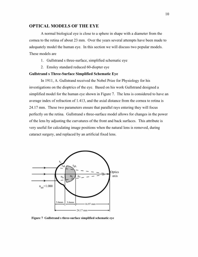
Gullstrand s Three-Surface Simplified Schematic Eye
In 1911, A. Gullstrand received the Nobel Prize for Physiology for his
investigations on the dioptrics of the eye. Based on his work Gullstrand designed a
simplified model for the human eye shown in Figure 7. The lens is considered to have an
average index of refraction of 1.413, and the axial distance from the cornea to retina is
24.17 mm. These two parameters ensure that parallel rays entering they will focus
perfectly on the retina. Gullstrand s three-surface model allows for changes in the power
of the lens by adjusting the curvatures of the front and back surfaces. This attribute is
very useful for calculating image positions when the natural lens is removed, during
cataract surgery, and replaced by an artificial fixed lens.
Figure 7 Gullstrand s three-surface simplified schematic eye

11
Emsley Standard Reduced 60-Diopter Eye
The Emsley standard reduced 60-diopter eye is one of the simplest models of the
eye and most often used in ophthalmic education (Figure 8). It contains a single
refracting surface and only one index of refraction mismatch between the air and the
vitreous humor. The axial distance from the cornea to the retina is 22.22 mm. Unlike the
three-surface simplified schematic model, accommodation calculations cannot be done.
The two principal points and two nodal points are combined into single principal and
nodal points (H and N). The corneal surface of 60 D power encompasses the separate
refractions of the corneal and lens interfaces, representing the total focusing power for the
eye.
DEFECTIVE VISION AND ITS CORRECTION
When you go to the optometrist to get your eyes check you probably looked at a
Snellen chart similar to the one shown in Figure 9. These charts test the visual acuity of
your eyes and help the doctor determine whether you need corrective lenses. Simply
stated, visual acuity is the ability to see clearly or the resolution of the eye. If your
eyes test normal at 20/20, it means that you can read letters from 20 ft that a person with
Figure 8 Emsley s standard reduced 60-diopter eye.

12
good vision would read 20 ft away. If your eyes test at 20/40, then you can read
something from 20 ft away that a person with good vision can read 40 ft away.
A normal, 20/20 eye is called emmetropic when rays from a distant object and a
near object can come to a focus on the retina. An eye unable to do either or both of these
tasks is called ametropic. There are three common defects in vision: myopia, hyperopia,
and presbyopia. Each of these conditions and how they are commonly corrected are
explained in detail below.
Myopia
Myopia, or near-sightedness, is a very common condition among young adults. A
myopic person is unable to clearly see a distant object yet is able to focus near objects
(Figure 10). A myopic eye has too large refracting power for a longer-than-normal eye.
Light rays from a distant object focus in front of the retina producing a blurry image on
the retina. The myopic far point (MFP) is the farthest distance an object is located from
Figure 9 Snellen eye chart. Charts likethese are commonly used to test a person svisual acuity.

13
the eye that still produces a focused image on the retina. A fully accommodated myopic
eye can focus objects closer to the eye than normal. This distance is called the myopic
near point (MNP).
Hyperopia,
Hyperopia is more commonly known as far-sightedness. A hyperopic person is
unable to clearly see near-by objects. Opposite of the myopic eye, the hyperopic eye has
too little converging power for the shorter-than-normal eye. As illustrated in Figure 11a,
a hyperopic eye never focuses the light coming from a near-by object before it hits the
retina. Thus, a sharp image is never formed on the retina. The focal point behind the
retina is considered the hyperopic far point (HFP). A partially accommodated
hyperopic eye can still focus objects far away. When the eye is fully accommodated, the
nearest distance of an object from the eye that will produce a focused image on the retina
is called the hyperopic near point (HNP).
Figure 10 A comparison of (a) normal and (b) myopic vision (c) with correction.

14
Presbyopia
Presbyopia is a condition where the eye loses its ability to accommodate with age.
Recall, the ciliary muscle contracts and squeezes the lens so that it has a shorter focal
length to accommodate for near point objects. Over time, the crystalline lens gradually
hardens, decreasing the flexibility of the lens, making it more difficult to focus near-by
objects. Loss of accommodation begins at a very early age; however not until the age of
about 40 years will a person begin noticing they have trouble reading fine print and need
to hold a book farther away to focus clearly.
Vision Correction
Myopia, hyperopia, and presbyopia are routinely corrected with spectacles. Too
much convergence (positive power) causes myopia, a negative power, or diverging lens is
Figure 11 Hyperopic vision with correction.
15
used to refocus rays from far distances onto the retina (Figure 10c). The negative lens
will move the myopic far and near points outward to normal positions. Conversely a
hyperopic eye requires a positive power lens to move the hyperopic near and far points
inward (Figure 11b). As one may suspect from its name, lens maker s equation is used to
calculate the lens power needed to correct either condition. Presbyopic correction is
similar to hyperopia in that a positive lens will compensate for the eye s inability to
accommodate. Presbyopes usually wear reading spectacles for near point activities, such
as reading. A presbyopic person who already wears spectacles to correct myopia or
hyperopia will usually switch to bifocals.
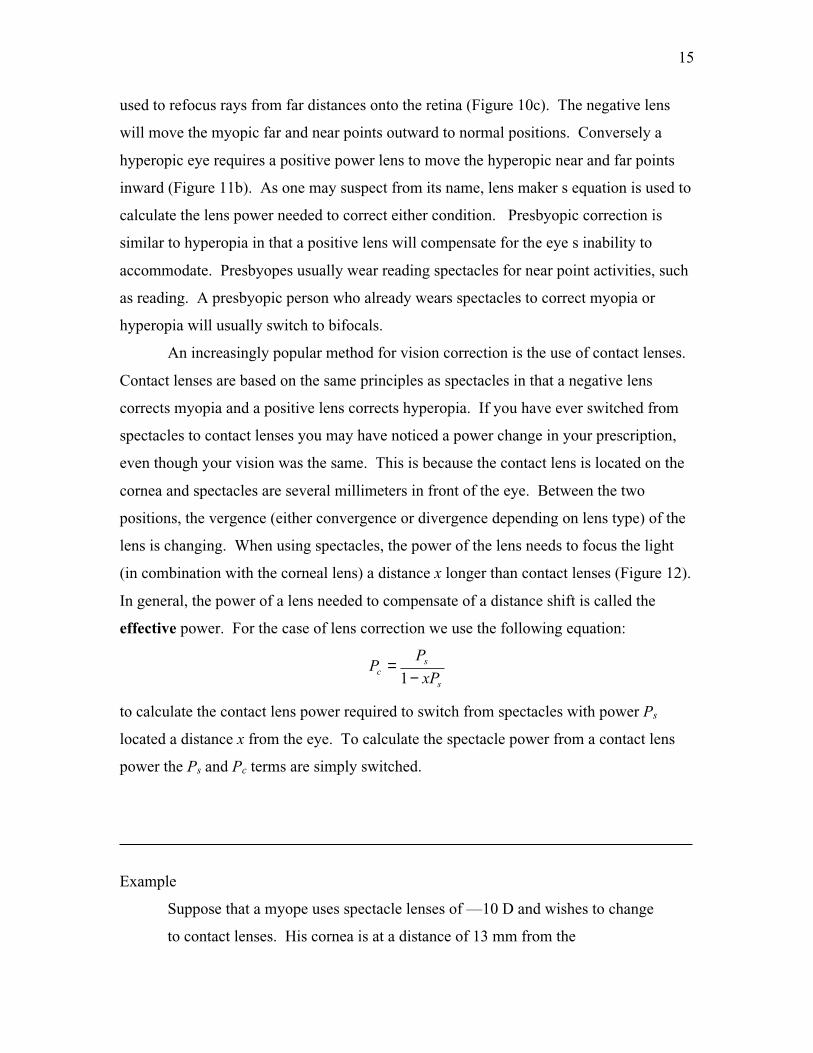
An increasingly popular method for vision correction is the use of contact lenses.
Contact lenses are based on the same principles as spectacles in that a negative lens
corrects myopia and a positive lens corrects hyperopia. If you have ever switched from
spectacles to contact lenses you may have noticed a power change in your prescription,
even though your vision was the same. This is because the contact lens is located on the
cornea and spectacles are several millimeters in front of the eye. Between the two
positions, the vergence (either convergence or divergence depending on lens type) of the
lens is changing. When using spectacles, the power of the lens needs to focus the light
(in combination with the corneal lens) a distance x longer than contact lenses (Figure 12).
In general, the power of a lens needed to compensate of a distance shift is called the
effective power. For the case of lens correction we use the following equation:
s
sc xP
PP
−=
1
to calculate the contact lens power required to switch from spectacles with power Ps
located a distance x from the eye. To calculate the spectacle power from a contact lens
power the Ps and Pc terms are simply switched.
Example
Suppose that a myope uses spectacle lenses of —10 D and wishes to change
to contact lenses. His cornea is at a distance of 13 mm from the

16
spectacles. What should be the contact lens power to provide equivalent
correction?
Solution Now, x = 13 mm, and P = -10 D. Then
DxP
PP
s
sc 85.8
)10)(013(.1
10
1−=
−−−=
−=
The contact lens must be of lesser negative power than the spectacle lens
due to the decrease in vergence of the light.
ABERRATIONS OF THE EYE
By assuming that all the rays that hit lenses is paraxial, we have ignored the
dispersive effect caused by lenses. Saying that spherical lenses and mirrors produce
perfect images is not entirely correct. Even when ground and polished perfectly, lenses
do not produce perfect images. The deviations of rays from what is ideally expected are
called aberrations. There are five main types of aberrations: spherical, astigmatism,
coma, field curvature, and distortion.
Figure 12 Equivalent correction of (a) amyopic eye by using either (b) a spectaclelens a distance x from the cornea or (c) acontact lens at the cornea. Prescriptionpower differs between the spectacle lensand contact lens.
Figure 13 Spherical aberrationin a converging lens. Theparaxial rays, I, have the farthestfocal point, FI. The outer rays, O,bend the most and therefore havethe closest focal point, FO. Themiddle rays, M, focus betweenthe two extremes.

17
Spherical Aberrations
When paraxial rays pass through the edges of a spherical lens they do not pass
through the same focus (Figure 13). A blurred image formed due to the deviations of the
rays passing through the edges of the lens is called spherical aberration. As you may
imagine, spherical aberrations are a greater problem is optical systems with large
apertures. Under normal conditions, the human pupil is small enough that spherical
aberrations do not significantly affect vision. Under low-light conditions or when the
pupil is dilated, however, spherical aberrations become important. The visual acuity
becomes affected when the pupil is larger than about 2.5 mm in diameter. So, as you
may recall, if the pupil size become too small, the visual acuity decreases due to
diffraction. Yet, when the pupil size becomes too big, spherical aberrations will too
decrease visual acuity.
There are other factors of the eye that reduces the effect of spherical aberrations.
The outer portions of the cornea have a flatter shape and therefore refract less than the
central areas. The central part of the crystalline lens also refracts more than its outer
portions due to a slightly higher refractive index at its center.
Spherical aberrations can be correcting using aspheric spectacle lenses. Aspheric
lenses have surfaces that are not exactly spherical. The aspheric lens is designed to
correct for excessive refraction that may occur around the edges of the cornea.
Coma
Coma is an off-axis modification of spherical aberration. Coma produces a
blurred image, shaped like a comet, of off axis objects (figure 14). Like spherical
aberration, coma is a pupil size dependent aberration of the eye. It can also be corrected
using an aspheric lens. An optical system free of both coma and spherical aberration is
called aplantic.
(a)(b)

18
Astigmatism
Astigmatism is a difference in focal length for rays coming in different planes
from an off-axis object. Like coma, astigmatism is nonsymmetric about the optical axis.
The eye defect called astigmatism is slightly different than the optical aberration. The
eye defect, astigmatism refers to a cornea that is not spherical but is more curved in onw
plane than in another. In other words, the focal length of the astigmatic eye is different
for rays in one plane than for those in its perpendicular plane. Ocular astigmatism is
corrected by a lens that converges (or diverges) rays in specific planes, while not
affecting rays in the perpendicular plane. These lenses are called cylindrical lenses. The
cylindrical component of a patient s spectacle prescription refers to the correction of
astigmatism.
Field Curvature
Field curvature causes a plane surface object perpendicular to the optical axis to
image as a curved surface (figure 15). This aberration is remedied by using a curved
imaging plane. Field curvature is not an important aberration of the eye. The curvature
of the retinal surface corrects for curvature in the image.
Distortion
Distortion is a variation in the lateral magnification for object points at different
distances from the optical axis (figure 16). If magnification increases with the object
Figure 14 Coma (a) due to parallel rays, each image point in the figure becomes the top of acomatic circle of image points. (c) Formation of a comatic image from a series of comaticcircles. The angle between the dashed lines is 60o.
Figure 15 Curvature of field dueto a converging lens

19
point distance from the optical axis the image of figure 16a will look like figure 16b,
called pincushion distortion. Conversely if the magnification decreases with object point
distance the image has barrel distortion figure 16c. Both images are still sharp, just
distorted. There is little distortion in the eye itself.
DIRECT OPHTHALMOSCOPE
The direct ophthalmoscope is a hand-held, self-illuminating optical instrument
that allows a physician to look into a patient s eye. Hermann von Helmholtz invented the
ophthalmoscope in 1851 to view the optic disk, retina, blood vessels and other contents
found at the back surface of the eye. Figure 17a shows a simplified schematic of the
ophthalmoscope. The bright light from the source is reflected off of an angled mirror into
the subject s eye. The light diverges toward the lens system of the subject s eye.
Assuming both the subject and observer have emmetropic eyes, the rays are parallel to
each other because the retina is located one focal length from the lens. Light from the
illuminated part of the retina leaves the lens system of the subject s eye in the form of
parallel rays towards the observer. Because the rays are parallel, the lens system of the
observer s eye treats the image of the
subject s retina as a distant object and focuses it to a spot on their retina. Figure 17b
shows what one would see if they were looking at a normal retina through the
ophthalmoscope.
To correct for hyperopia or myopia of the subject and/or observer a variety of
corrective lenses are available within the ophthalmoscope. As noted above, the
ophthalmoscope is designed so that the observer s lens system can image the subject s
retina as though it is far away from the observer. Normal adult eyes have a tendency to
(a) (b) (c)
Figure 16 Images of (a) a square, (b)showing pincusion distortion, and (c) barreldistortion, due to nonuniformmagnifications.

20
accommodate when two eyes come close together. This accommodation causes an
approximate +2 D increase in strength in the lens of the eye. So even for the case of both
an emmetropic subject and observer, it is very likely a — 4 D lens is needed to see a clear
image of the subject s retina.
(b)
Figure 17 (a) schematic of a directophthalmoscope. (b) image of a retinaas seen through an ophthalmoscope
References:• Pedrotti L and Pedrotti F; Optics and Vision. Prentice-Hall, New Jersey 1998.• Falk D, Brill D, and Stork D; Seeing the Light. John Wiley & Sons, New York 1986.• Cameron J, Skofronick J, and Grant R; Physics of the Body. Medical Physics
Publishing, Madison, Wisconsin 1999.

21
Sample Problem Set
1. Using Emsley s standard reduced 60D eye model, compute the size of an image of a
spider, 3mm in diameter, on the retina. The spider is on the wall 3.0m away.
Solution: From Emsley s model, we know that the image distance i , is 22.22mm. We
also know the cornea is a convex lens and will form a real, inverted image on the retina.
We calculate the magnification (or minification for this case) of the image of the spider is
31033.70.3
022.0 −×−=−=m
mm
And therefore the size of the image of the spider on the retina is mm31033.7 3 ×× − or
22µm. The negative sign indicates that the image is inverted.
2. Determine the strength of a lens needed to correct a myopic eye that has a far point of
2.0m.
Solution: To correct myopia we need a lens that will image an object located far away
onto the myopic far point. Recall, the myopic far point is the farthest distance from the
eye that an object can be so that the eye is still able to focus its image onto the retina.
Using the thin-lens equation for optical power
Dm
P
IOP
5.00.2
11 −=−
+∞
=
+=
we find that we need a negative lens with -0.5D to correct this vision.
3. Determine the strength of a lens needed to allow a hyperopic person that has a near
point of 2.0m to thread a needle 0.25m away.
Solution: To correct hyperopia we need a lens that will image an object that is close to
the eye onto the hyperopic near point. Recall that the hyperopic near point is the closest

22
distance an object can be to the eye so that its image is focused onto the retina. Using the
thin-lens equation for optical power
Dmm
P
IOP
5.30.2
1
25.0
1 =−
+=
+=
we find that we need a positive lens with 3.5D to correct this vision.
4. On examination, an optometrist finds that a patient who was formerly emmetropic
now has a near point of 0.5m and lies to read at a distance of 0.25m. What is this
condition called and what strength reading glasses should be prescribed?
Solution: We need to image the object onto the near point so the eye can properly focus
the intermediate image onto the retina.
Dmm
P
IOP
0.25.0
1
25.0
1 =−
+=
+=
The reading glasses should have strength of 2.0D.
5. Suppose the prescription power of a contact lens for hyperopia is +10D. If the person
is to be fitted instead with spectacle lenses, worn at a distance of 14mm from the cornea,
what is the required prescription?
Solution: Using the equation for effective power
DDm
DP
xP
PP
s
c
cs
77.8)10)(014.0(1
10
1
=−−
=
−=
The spectacle lens for the hyperope is 8.77D. It is lesser power than the contact lens
because the spectacle lens is farther from the cornea and therefore requires less
convergence.

23
Lab Experiments
The Optics of the Eye
Blind Spot
All of the nerves of the retina bundle together to form the optic nerve. Where the optic
nerve exits the eye there is a blind spot. At this spot there are no photoreceptors,
therefore no light can be detected. You can find your own blind spot.
Directions:
On a notecard draw an x and a large dot about 2 inches to the left of the x .
Close the left eye and focus the right eye on the x of the notecard.
Start the card about five inches from your eye and slowly move it away from you,
while maintaining focus on the x .
At a certain distance the dot will disappear. If you move the card even further, the
spot should reappear.
If you assume the fovea is located in the center of the retina, you can calculate the
distance from the fovea to the optic disk by measuring the distance the notecard is
from your eye.
Inverted Image
The image formed by the lens of the eye onto your retina is inverted, or upside down.
Objects appear upright because your brain will revert the image back to normal.
However, if an object is placed within the primary focal distance of the eye, it forms a
blurred image on the retina that is also inverted.
Directions:
Position a pinhole about an inch from one eye.
Now hold the tip of a pen between the pinhole and your eye. You should see an
inverted image of the pen tip.
By measuring the distance between the pen tip and your eye, you can draw a ray-
tracing diagram to show exactly how the image forms on your retina.

24
You can also see that images are inverted on the retina by doing the following:
While looking at a white sheet of paper, gently press the outside of one eye, you
should see a black spot form near your nose.
It is believed that by gently pressing on the eye, blood flow to that area on the
retina is restricted, thus you see a dark spot. The spot you see, however, is toward
the opposite side of the finger because the image on the retina is inverted. Light
from the side near your ear is imaged on the part of your retina near your nose.
The Optics of the Eye II
Using an Ophthalmoscope
As you know, doctors use ophthalmoscopes to view the back of their patient s eye. In
your handout a simple diagram of on ophthalmoscope is provided (Figure 8). Here you
can learn how to look through an ophthalmoscope and observe your partner s retina.
Directions:
To turn on the power source, press down on the green button and twist the ring.
Bring the flat side of the scope up to you eye, looking through the aperture.
Find the correct corrective lens so that objects are in focus.
While looking through the scope, bring it near your partner s eye, slightly from
the side, so that the light is shining into his/her pupil but not from straight on.
Move the scope slightly until you see an image like the one in Figure 9 of your
handout.
If the image is not clear, change the power of the corrective lens until it is.
Measuring your Eyeglass Prescription
You can easily measure the prescription of your eyeglasses. Your eyeglass prescription
is simply the power (in diopters) of your lenses. If you do not suffer from astigmatism,
25
your eyeglass lenses are spherical lenses and you need only measure the focal length of
each lens to determine its power.
There are several ways you can determine the focal length of a lens. Here is one
suggestion:
Using a distant light source, say the ceiling room lights, you can focus the image
of the lights onto a screen (white paper) on the floor using a lens.
Move the lens farther away from the floor until the image of the lights is focused
on the screen.
The focal length of the lens is the distance between the screen and the lens.
You can then calculate the power of the lens in diopters.
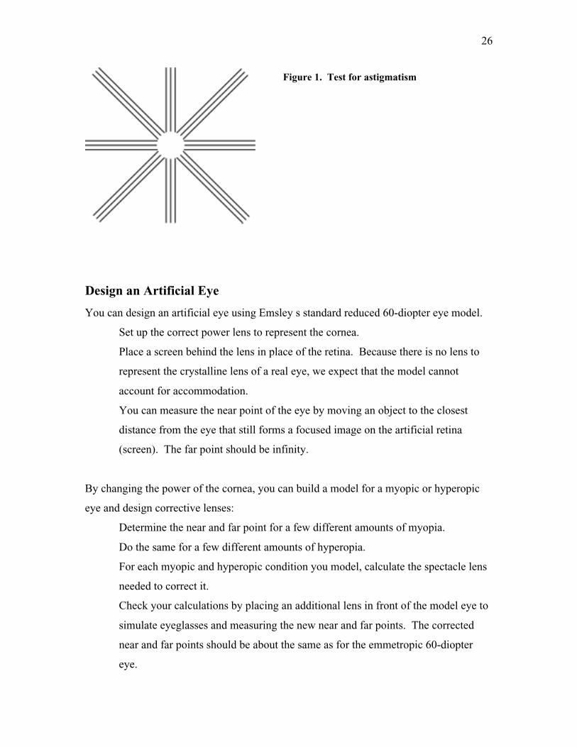
Test for astigmatism.
Here is a simple test for astigmatism:
Close one eye and view Figure 1 through the other eye (without glasses or contact
lenses).
Hold the figure sufficiently close to the eye so that all lines look blurred.
Gradually move the figure away until one set of lines comes into focus, with the
rest blurred. (If two adjacent sets come into focus together, rotate the figure a
little until only one is in focus. If all sets come into focus together, you don t
have astigmatism.) You have now found the near point for a line in a direction of
the lines that are in focus.
Move the pattern away further until the lines perpendicular to the first set come
into focus. (The first set may or may not remain in focus.) This is the near point
for a line perpendicular to the original set.
The different near points mean that your eye has a different focal length for lines
parallel to and perpendicular to the original set.
Try the procedure again with your glasses or contact lenses to see if your
astigmatism is corrected.
26
Design an Artificial Eye
You can design an artificial eye using Emsley s standard reduced 60-diopter eye model.
Set up the correct power lens to represent the cornea.
Place a screen behind the lens in place of the retina. Because there is no lens to
represent the crystalline lens of a real eye, we expect that the model cannot
account for accommodation.
You can measure the near point of the eye by moving an object to the closest
distance from the eye that still forms a focused image on the artificial retina
(screen). The far point should be infinity.
By changing the power of the cornea, you can build a model for a myopic or hyperopic
eye and design corrective lenses:
Determine the near and far point for a few different amounts of myopia.
Do the same for a few different amounts of hyperopia.
For each myopic and hyperopic condition you model, calculate the spectacle lens
needed to correct it.
Check your calculations by placing an additional lens in front of the model eye to
simulate eyeglasses and measuring the new near and far points. The corrected
near and far points should be about the same as for the emmetropic 60-diopter
eye.
Figure 1. Test for astigmatism

27