Embed Size (px)
Citation preview
POSTERIO-ANTERIOR CEPHALOMETRIC ANALYSIS
By:Dr Jasmine Arneja
Precepted by:Dr ShalajDr vishal
Introduction Setup General landmarks MSR Ricketts analysis Grummons analysis Hewitts analysis Svanholt and Solow analysis Grayson analysis conclusion
Contents:
In orthodontics, the primary indication for obtaining a posteroanterior cephalometric film is the presence of facial asymmetry.
it is also important in cases of dentoalveolar asymmetries, dental and skeletal crossbites, and functional mandibular displacements. (transverse discrepancies)
The posteroanterior cephalometric projection, also called as the Caldwell projection.
Introduction
A headholder or a cephalostat that can be rotated 90° is used, so that the central X-ray beam penetrates the skull of the patient in a posteroanterior direction and bisects the transmeatal axis perpendicularly.
The standard distance from X-ray source to patient is 5 feet (152.4 cm)
The tip of the nose and forehead should lightly touch the cassette and the FHP should be parallel to the floor
Cephalometric set-up
No double shadows The top of the petrous portion of the
temporal bone should lie near the center of the orbit
Sign of a good PA cephalogram
Being a more reproducible position, NHP is now frequently used. Natural head position is a standardized orientation of the head, which is readily assumed by focusing on a distant point at eye level (Moorrees, 1985).
Reproducibility of natural head position, assessed as the error of a single observation, has been found to be close to 2°, which supports its use in cephalometry (Lundstrom and Lundstrom, 1992).
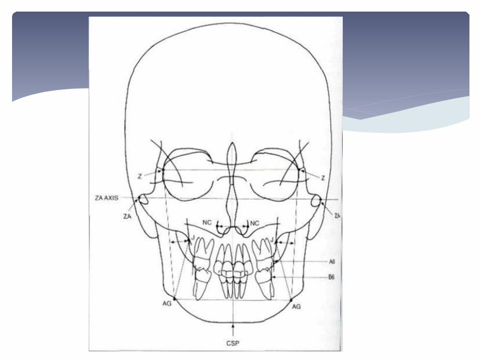
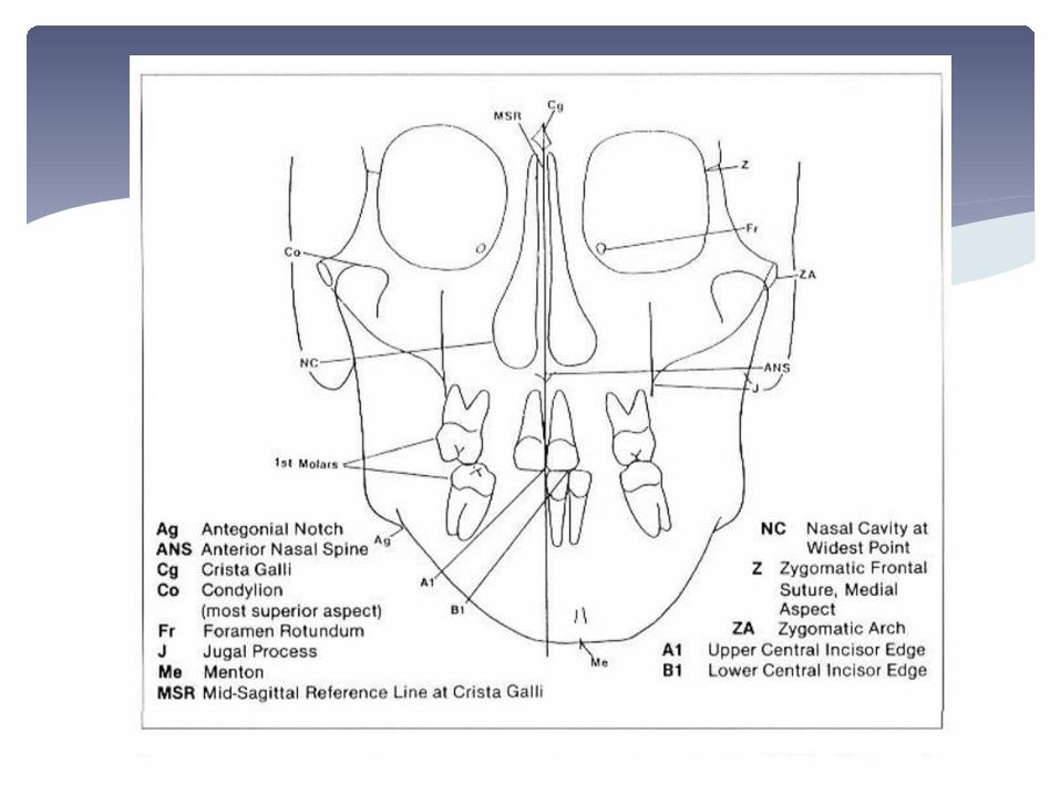
LANDMARKS
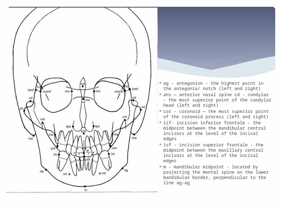
ag - antegonion - the highest point in the antegonia/ notch (left and right)
ans — anterior nasal spine cd - condylar - the most superior point of the condylar head (left and right)
cor - coronoid — the most superior point of the coronoid process (left and right)
iif- incision inferior frontale - the midpoint between the mandibular central incisors at the level of the incisal edges
isf - incision superior frontale - the midpoint between the maxillary central incisors at the level of the incisal edges
m - mandibular midpoint - located by projecting the mental spine on the lower mandibular border, perpendicular to the line ag-ag
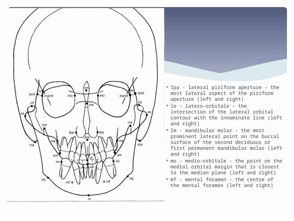
Ipa - lateral piriform aperture - the most lateral aspect of the piriform aperture (left and right)
lo - latero-orbitale - the intersection of the lateral orbital contour with the innominate line (left and right)
Im - mandibular molar - the most prominent lateral point on the buccal surface of the second deciduous or first permanent mandibular molar (left and right)
mo - medio-orbitale - the point on the medial orbital margin that is closest to the median plane (left and right)
mf - mental foramen - the centre of the mental foramen (left and right)
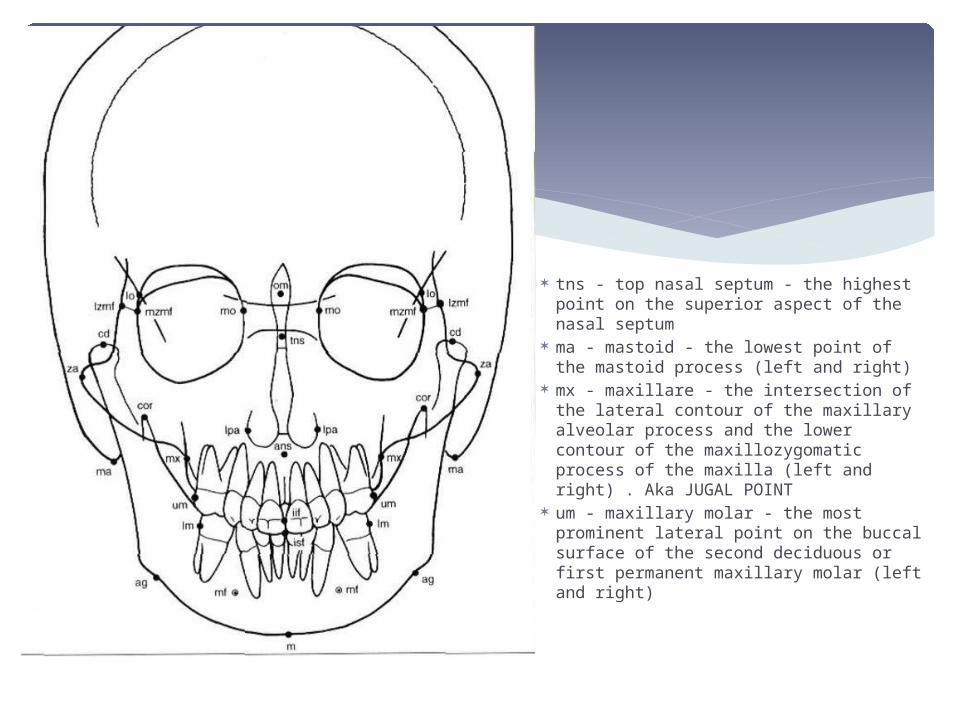
tns - top nasal septum - the highest point on the superior aspect of the nasal septum
ma - mastoid - the lowest point of the mastoid process (left and right)
mx - maxillare - the intersection of the lateral contour of the maxillary alveolar process and the lower contour of the maxillozygomatic process of the maxilla (left and right) . Aka JUGAL POINT
um - maxillary molar - the most prominent lateral point on the buccal surface of the second deciduous or first permanent maxillary molar (left and right)

za - point zygomatic arch - point at the
most lateral border of the centre of the zygomatic arch (left and right)
mzmf - zygomatic ofrontal medial suture point-in - point at the medial margin of the zygomaticofrontal suture (left and right)
Izmf - zygomaticofrontal lateral suture point-out - point at the lateral margin of the zygomaticofrontal suture (left and right)
A1 point- point selected at the interdental papilla of the upper incisors at the junction of crown and gingiva
B1 point- point selected at the interdental papilla of the lower incisors at the junction of crown and gingiva
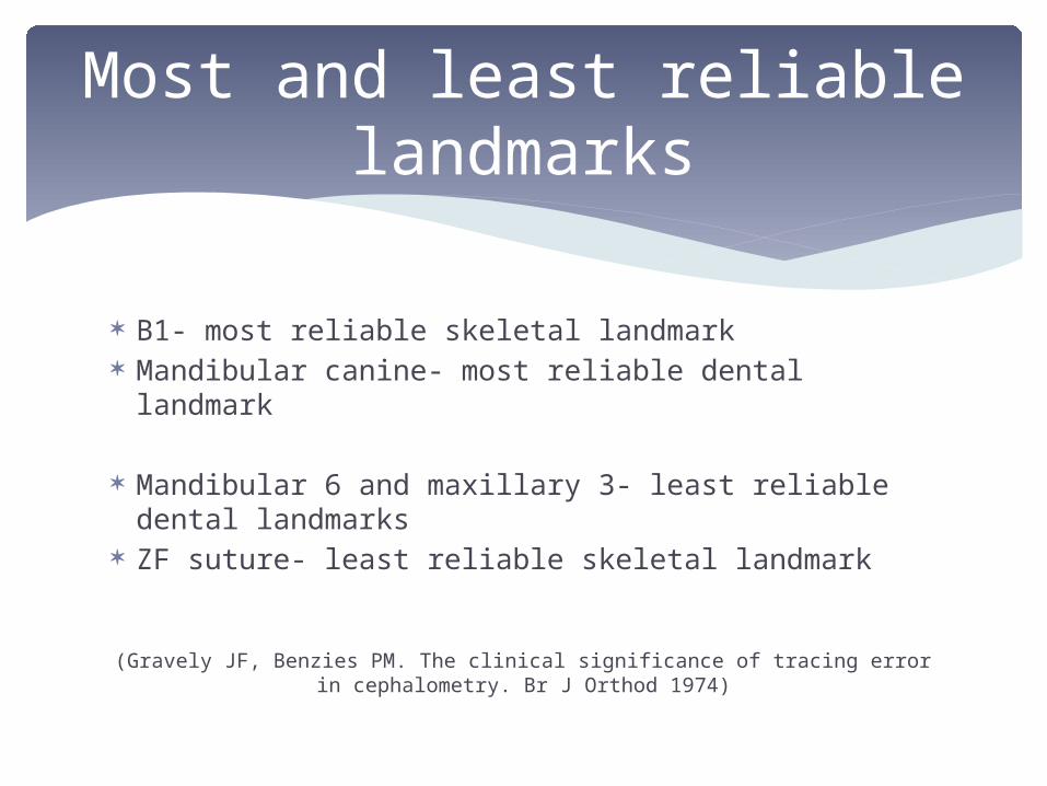
B1- most reliable skeletal landmark Mandibular canine- most reliable dental landmark
Mandibular 6 and maxillary 3- least reliable dental landmarks
ZF suture- least reliable skeletal landmark
(Gravely JF, Benzies PM. The clinical significance of tracing error in cephalometry. Br J Orthod 1974)
Most and least reliable landmarks
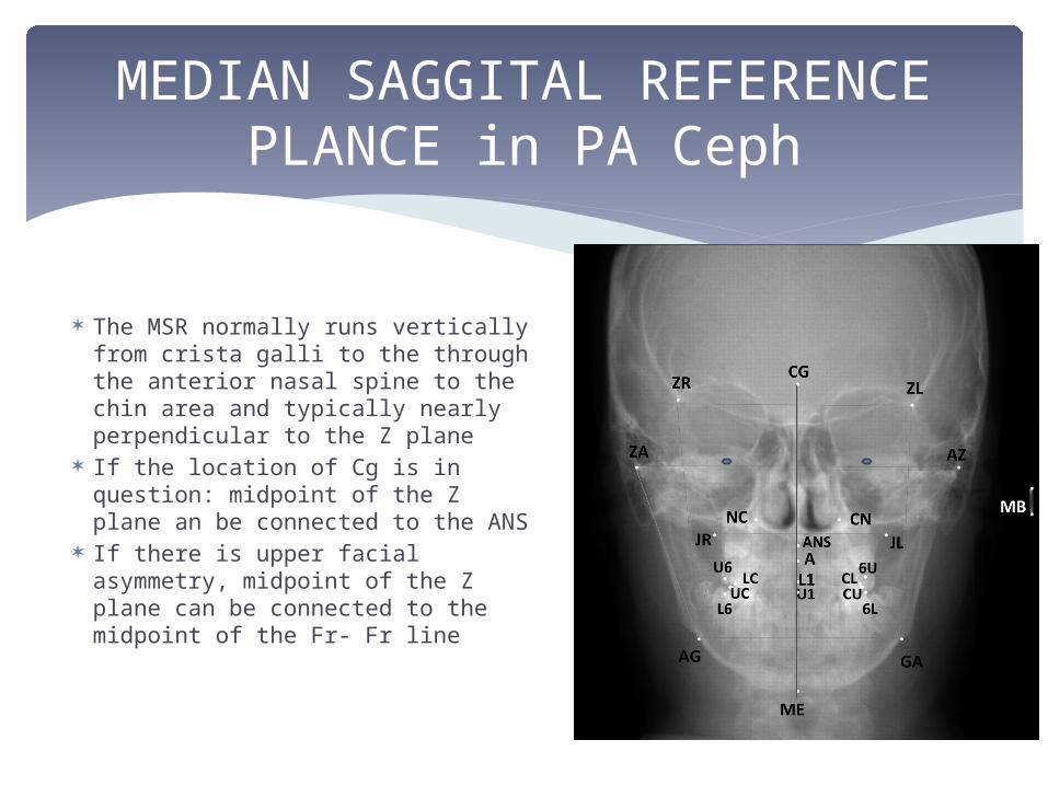
The MSR normally runs vertically from crista galli to the through the anterior nasal spine to the chin area and typically nearly perpendicular to the Z plane
If the location of Cg is in question: midpoint of the Z plane an be connected to the ANS
If there is upper facial asymmetry, midpoint of the Z plane can be connected to the midpoint of the Fr- Fr line
MEDIAN SAGGITAL REFERENCE PLANCE in PA Ceph
Most of the posteroanterior cephalomctric analyses described in the literature are quantitative, and they evaluate the craniofacial skeleton by means of linear absolute measurements of:
width or height (Solow, 1966; Ricketts et al, 1972; Ingerslev and Solow, 1975; Movers et al, 1988; Nakasima and Ichinose, 1984; Grummons and Kappeyne van de Coppello, 1987; Athanasiou et al, 1992);
angles (Ricketts et al, 1972; Svanholt and Solow, 1977; Droschl, 1984; Grummons and Kappeyne vande Coppello, 1987; Athanasiou et al, 1992);
ratios (Costaras et al, 1982; Grummons and Kappeyne van de Coppello, 1987; Athanasiou et al, 1992); and
volumetric comparison (Grummons and Kappeyne van de Coppello, 1987).
The different structures of the craniofacial complex can also be analysed using qualitative methods (Sollar, 1947; Grayson et al, 1983; Proffit, 1991).
The analysis proposed by Grummons and Kappeyne van de Coppello (1987) contains quantitative assessment of vertical dimensions and proportions.
PA ceph analysis
Ricketts gave a normative data of parameters measured, which is helpful in determining the vertical transverse skeletal and dental problems
It has the following components: Dental realtions Skeletal relations Dental to skeletal Jaw to cranium Internal structures
RICKETTS ANALYSIS
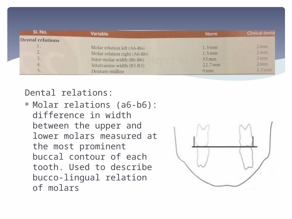
Dental relations: Molar relations (a6-b6):
difference in width between the upper and lower molars measured at the most prominent buccal contour of each tooth. Used to describe bucco-lingual relation of molars
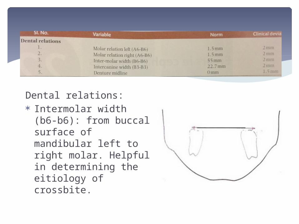
Dental relations: Intermolar width (b6-
b6): from buccal surface of mandibular left to right molar. Helpful in determining the eitiology of crossbite.
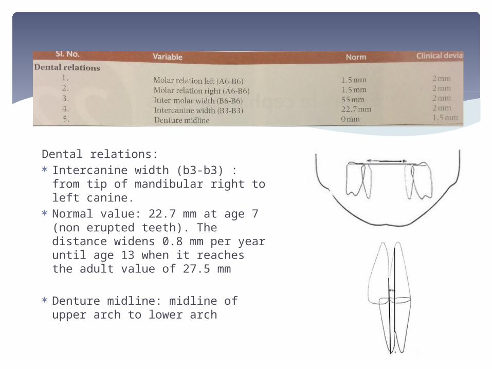
Dental relations: Intercanine width (b3-b3) : from tip
of mandibular right to left canine. Normal value: 22.7 mm at age 7
(non erupted teeth). The distance widens 0.8 mm per year until age 13 when it reaches the adult value of 27.5 mm
Denture midline: midline of upper arch to lower arch
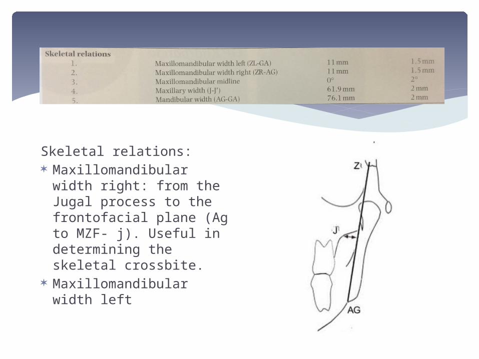
Skeletal relations: Maxillomandibular width
right: from the Jugal process to the frontofacial plane (Ag to MZF- j). Useful in determining the skeletal crossbite.
Maxillomandibular width left
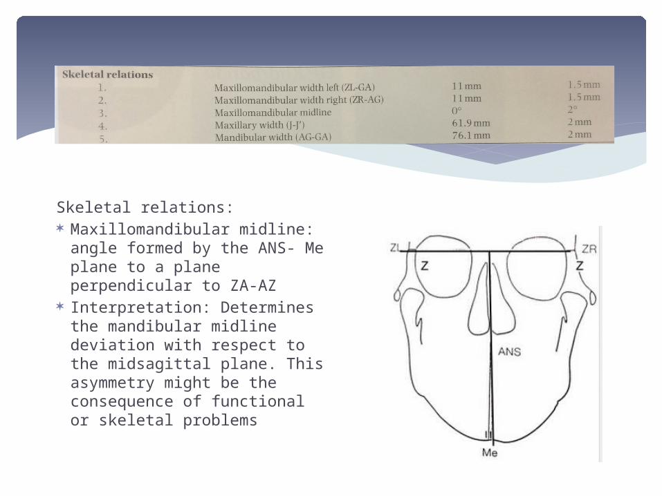
Skeletal relations: Maxillomandibular midline:
angle formed by the ANS- Me plane to a plane perpendicular to ZA-AZ
Interpretation: Determines the mandibular midline deviation with respect to the midsagittal plane. This asymmetry might be the consequence of functional or skeletal problems
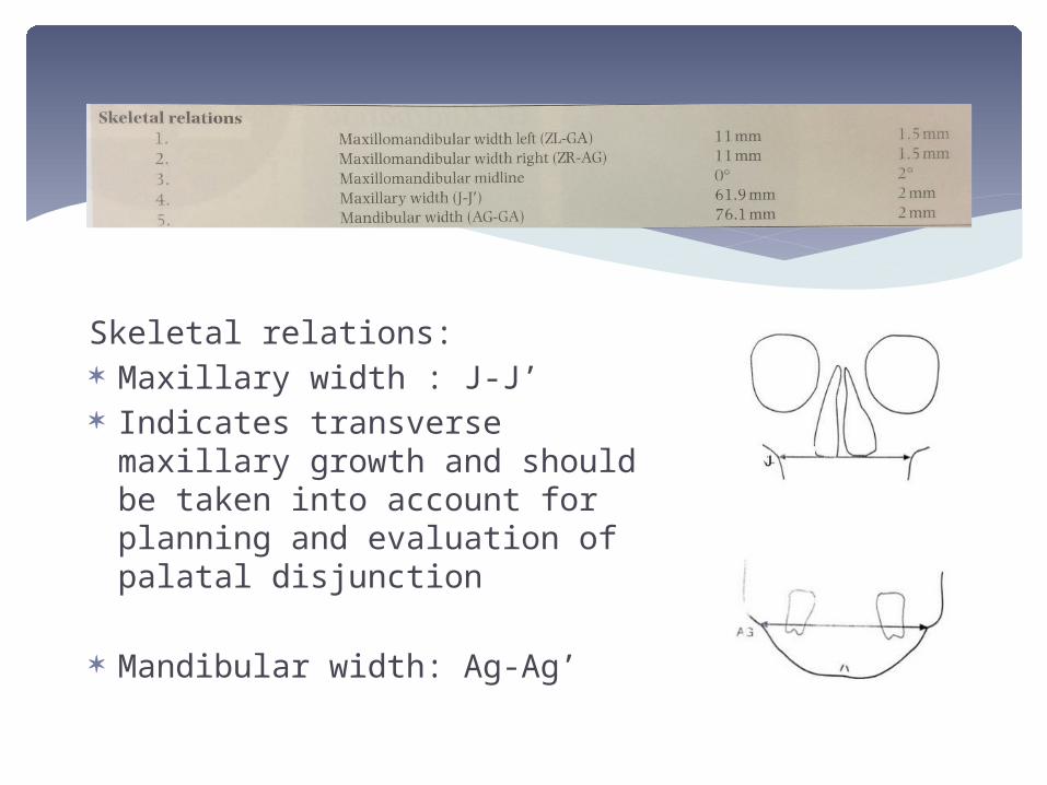
Skeletal relations: Maxillary width : J-J’ Indicates transverse maxillary
growth and should be taken into account for planning and evaluation of palatal disjunction
Mandibular width: Ag-Ag’
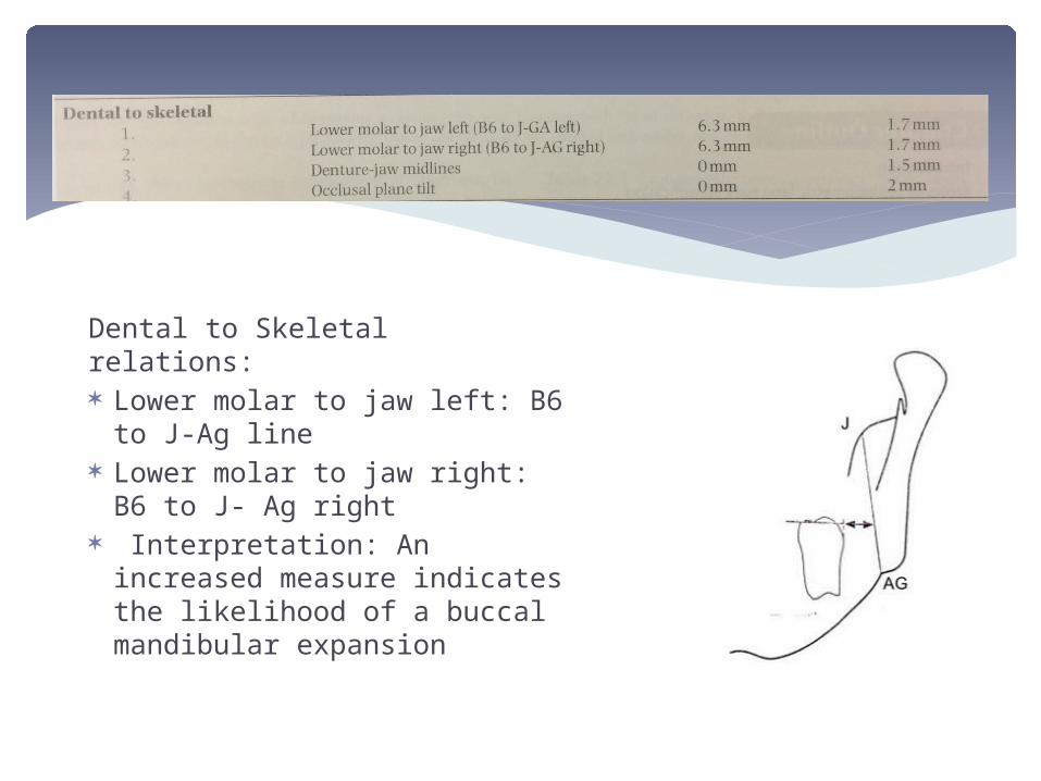
Dental to Skeletal relations: Lower molar to jaw left: B6
to J-Ag line Lower molar to jaw right: B6
to J- Ag right Interpretation: An increased
measure indicates the likelihood of a buccal mandibular expansion
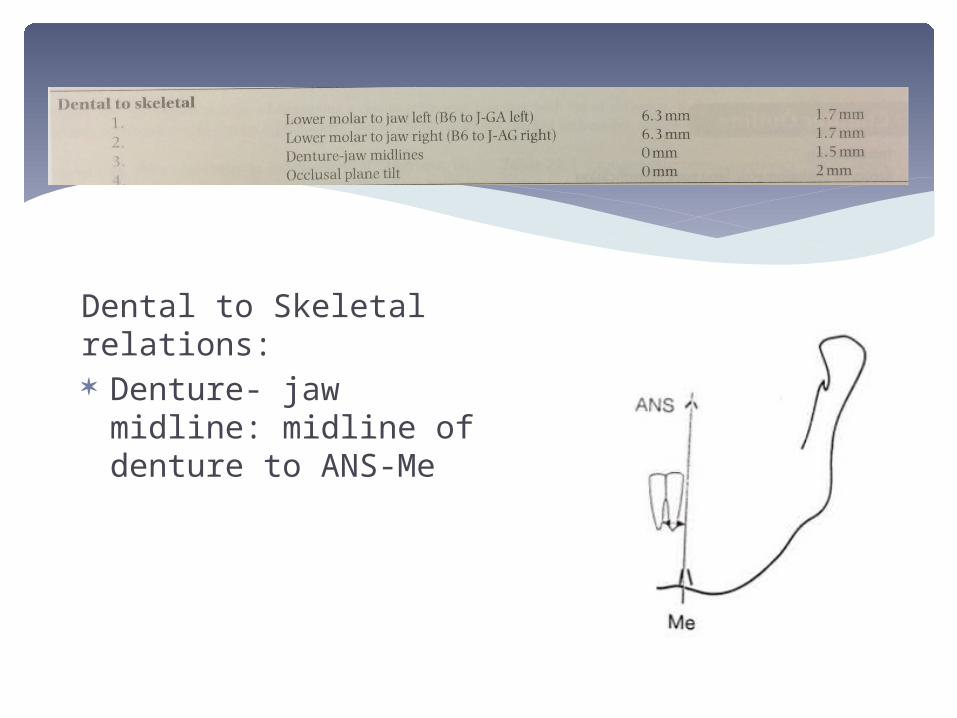
Dental to Skeletal relations: Denture- jaw midline:
midline of denture to ANS-Me
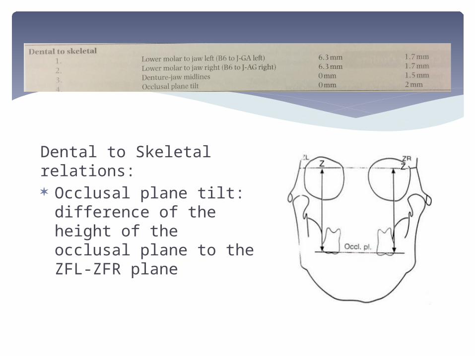
Dental to Skeletal relations: Occlusal plane tilt:
difference of the height of the occlusal plane to the ZFL-ZFR plane
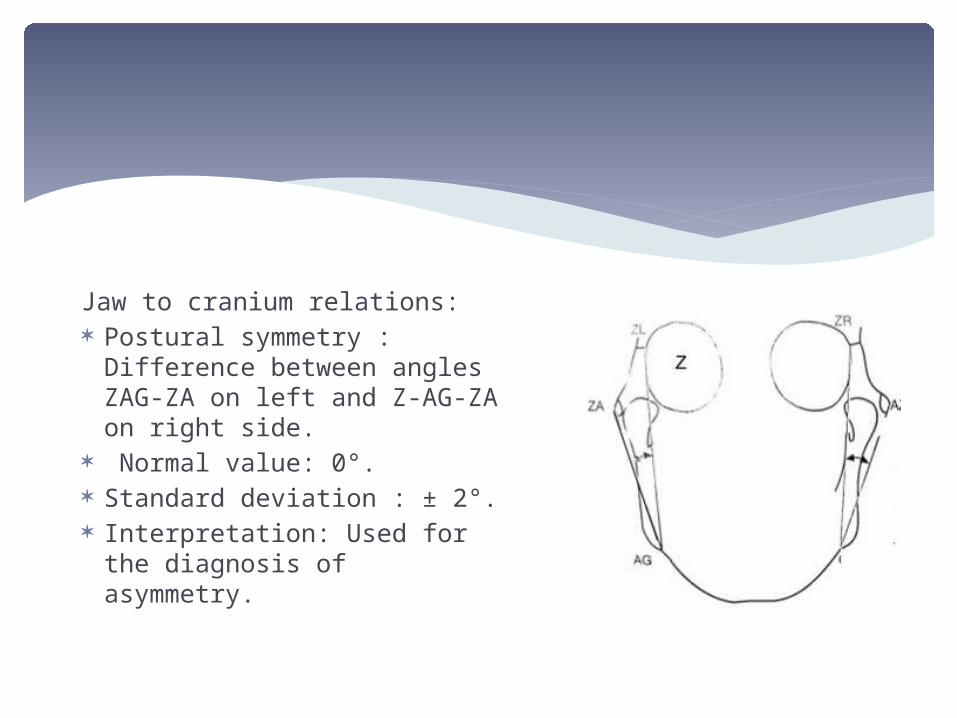
Jaw to cranium relations: Postural symmetry :
Difference between angles ZAG-ZA on left and Z-AG-ZA on right side.
Normal value: 0°. Standard deviation : ± 2°. Interpretation: Used for the
diagnosis of asymmetry.
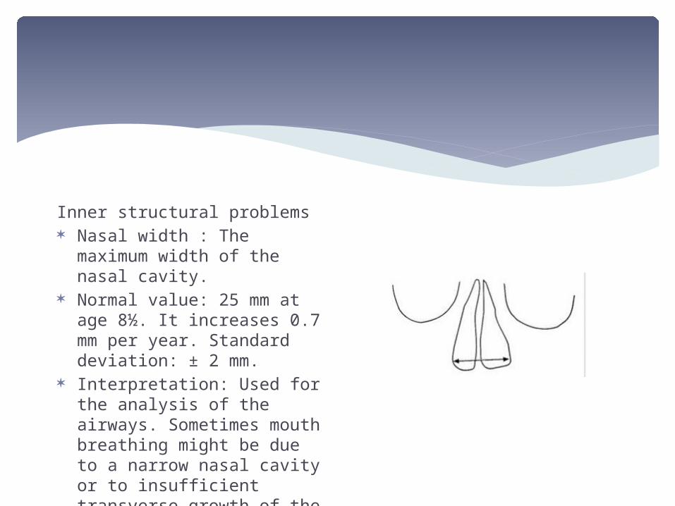
Inner structural problems Nasal width : The maximum
width of the nasal cavity. Normal value: 25 mm at age
8½. It increases 0.7 mm per year. Standard deviation: ± 2 mm.
Interpretation: Used for the analysis of the airways. Sometimes mouth breathing might be due to a narrow nasal cavity or to insufficient transverse growth of the maxilla.
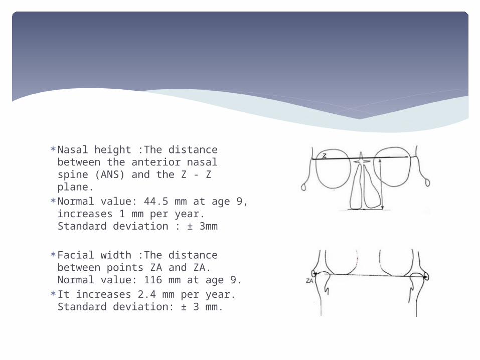
Nasal height :The distance between the anterior nasal spine (ANS) and the Z - Z plane.
Normal value: 44.5 mm at age 9, increases 1 mm per year. Standard deviation : ± 3mm
Facial width :The distance between points ZA and ZA. Normal value: 116 mm at age 9.
It increases 2.4 mm per year. Standard deviation: ± 3 mm.
This is a comparative and quantitative posteroanterior cephalometric analysis. It is not related to normative data.
The analysis is presented in two forms: the comprehensive frontal asymmetry analysis summary frontal asymmetry analysis.
The analyses consist of different components, including horizontal planes, mandibular morphology, volumetric comparison, maxillomandibular comparison of asymmetry, linear asymmetry assessment, maxillomandibular relation, and frontal vertical proportions
GRUMMONS ANALYSIS(Grummons and Kappeyne van de Coppello, 1987)
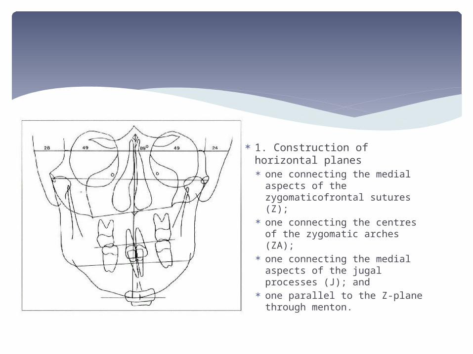
1. Construction of horizontal planes one connecting the medial
aspects of the zygomaticofrontal sutures (Z);
one connecting the centres of the zygomatic arches (ZA);
one connecting the medial aspects of the jugal processes (J); and
one parallel to the Z-plane through menton.

2. A midsagittal reference line (MSR) is constructed from crista galli (Cg) through the anterior nasal spine (ANS) to the chin area
An alternative way of constructing the MSR line, if anatomical variations in the upper and middle facial regions exist, is to draw a line from the midpoint of Z-plane either through ANS or through the midpoint of both foramina rotundum (Fr-Fr line)
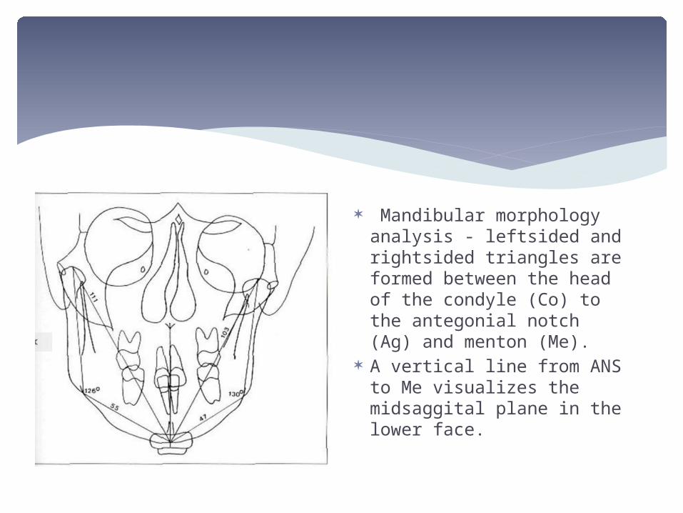
Mandibular morphology analysis - leftsided and rightsided triangles are formed between the head of the condyle (Co) to the antegonial notch (Ag) and menton (Me).
A vertical line from ANS to Me visualizes the midsaggital plane in the lower face.
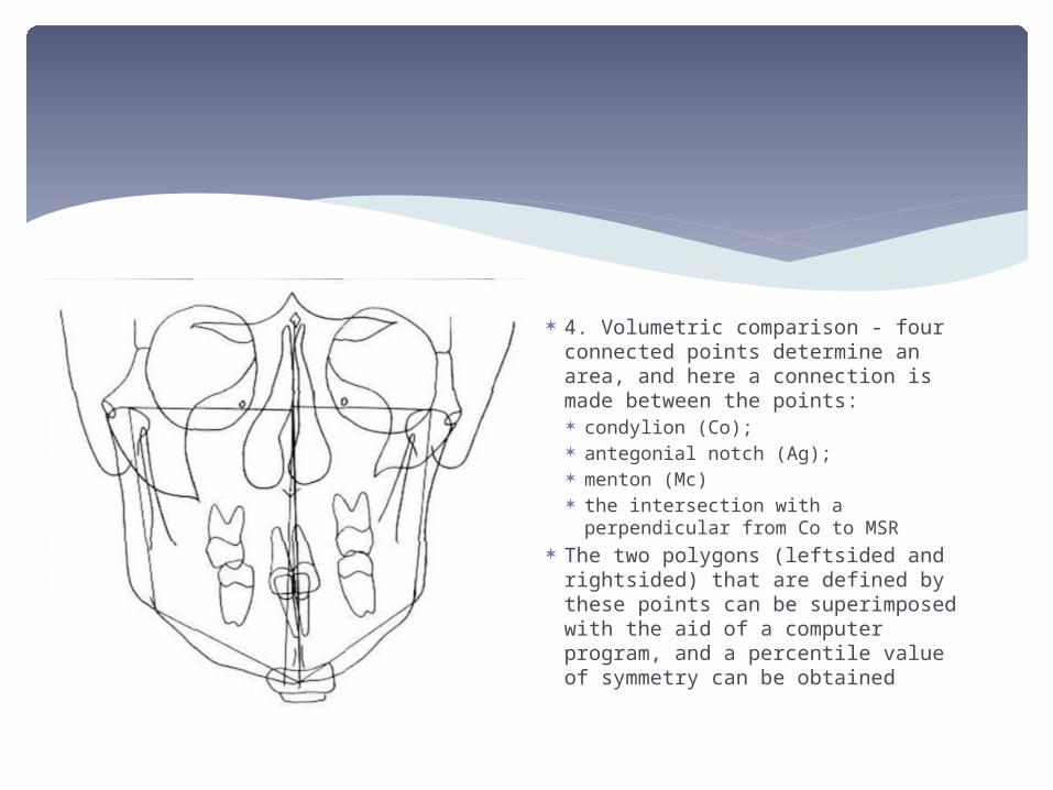
4. Volumetric comparison - four connected points determine an area, and here a connection is made between the points: condylion (Co); antegonial notch (Ag); menton (Mc) the intersection with a perpendicular
from Co to MSR The two polygons (leftsided and
rightsided) that are defined by these points can be superimposed with the aid of a computer program, and a percentile value of symmetry can be obtained
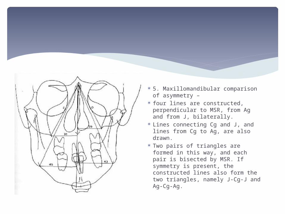
5. Maxillomandibular comparison of asymmetry –
four lines are constructed, perpendicular to MSR, from Ag and from J, bilaterally.
Lines connecting Cg and J, and lines from Cg to Ag, are also drawn.
Two pairs of triangles are formed in this way, and each pair is bisected by MSR. If symmetry is present, the constructed lines also form the two triangles, namely J-Cg-J and Ag-Cg-Ag.
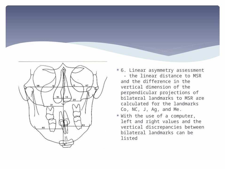
6. Linear asymmetry assessment - the linear distance to MSR and the difference in the vertical dimension of the perpendicular projections of bilateral landmarks to MSR are calculated for the landmarks Co, NC, J, Ag, and Me.
With the use of a computer, left and right values and the vertical discrepancies between bilateral landmarks can be listed
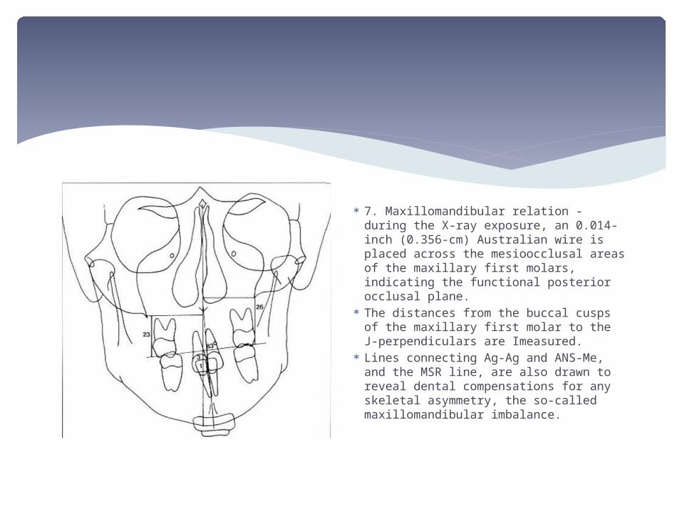
7. Maxillomandibular relation - during the X-ray exposure, an 0.014-inch (0.356-cm) Australian wire is placed across the mesioocclusal areas of the maxillary first molars, indicating the functional posterior occlusal plane.
The distances from the buccal cusps of the maxillary first molar to the J-perpendiculars are Imeasured.
Lines connecting Ag-Ag and ANS-Me, and the MSR line, are also drawn to reveal dental compensations for any skeletal asymmetry, the so-called maxillomandibular imbalance.
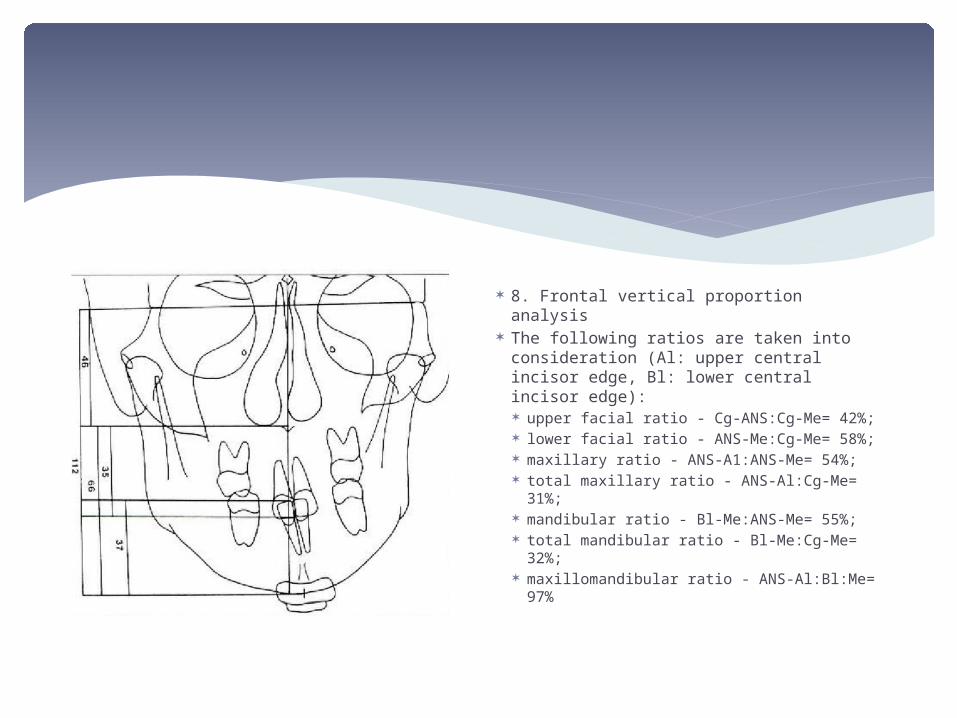
8. Frontal vertical proportion analysis The following ratios are taken into
consideration (Al: upper central incisor edge, Bl: lower central incisor edge): upper facial ratio - Cg-ANS:Cg-Me=
42%; lower facial ratio - ANS-Me:Cg-Me=
58%; maxillary ratio - ANS-A1:ANS-Me= 54%; total maxillary ratio - ANS-Al:Cg-Me=
31%; mandibular ratio - Bl-Me:ANS-Me= 55%; total mandibular ratio - Bl-Me:Cg-Me=
32%; maxillomandibular ratio - ANS-Al:Bl:Me=
97%
A method of analysing craniofacial asymmetry with the use of multiplane posteroanterior cephalometry has been developed by Grayson et al (1983).
Landmarks are identified in different frontal planes at selected depths of the craniofacial complex and subsequent skeletal midlines are constructed.
In this way, the analysis enables visualization of midlines and midpoints in the third (saggital) dimension. The midpoints and midlines may be combined and a 'warped midsaggital plane' can be the outcome of this analysis.
GRAYSON ANALYSIS
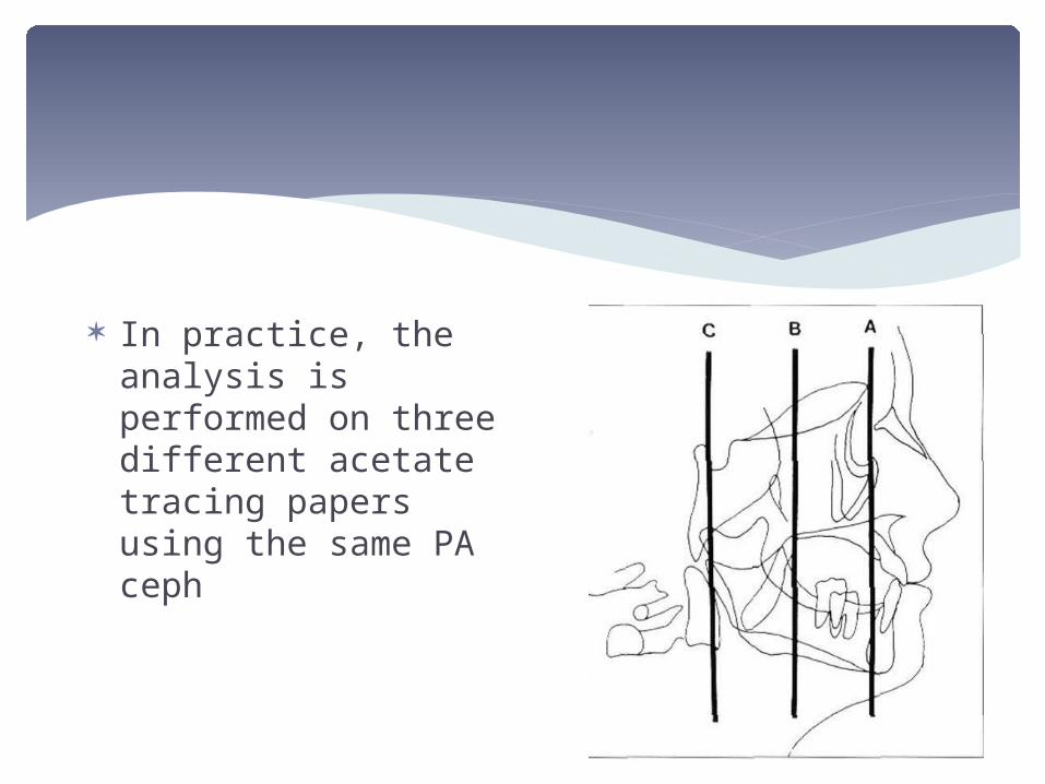
In practice, the analysis is performed on three different acetate tracing papers using the same PA ceph
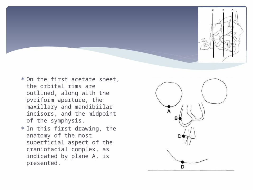
On the first acetate sheet, the orbital rims are outlined, along with the pvriform aperture, the maxillary and mandibiilar incisors, and the midpoint of the symphysis.
In this first drawing, the anatomy of the most superficial aspect of the craniofacial complex, as indicated by plane A, is presented.
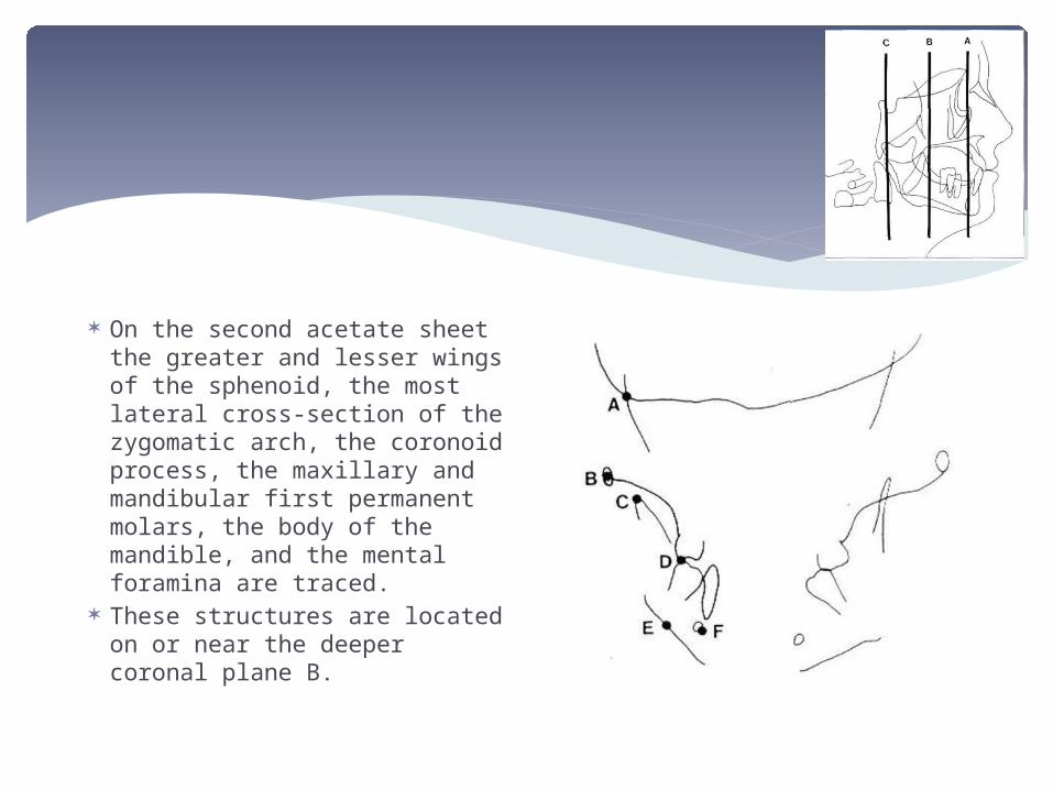
On the second acetate sheet the greater and lesser wings of the sphenoid, the most lateral cross-section of the zygomatic arch, the coronoid process, the maxillary and mandibular first permanent molars, the body of the mandible, and the mental foramina are traced.
These structures are located on or near the deeper coronal plane B.
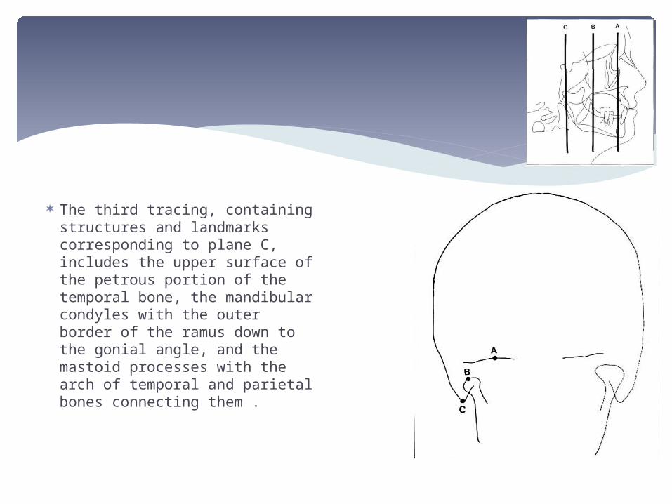
The third tracing, containing structures and landmarks corresponding to plane C, includes the upper surface of the petrous portion of the temporal bone, the mandibular condyles with the outer border of the ramus down to the gonial angle, and the mastoid processes with the arch of temporal and parietal bones connecting them .
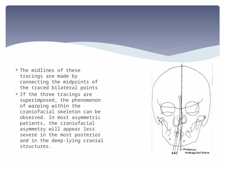
The midlines of these tracings are made by connecting the midpoints of the traced bilateral points
If the three tracings are superimposed, the phenomenon of warping within the craniofacial skeleton can be observed. In most asymmetric patients, the craniofacial asymmetry will appear less severe in the most posterior and in the deep-lying cranial structures.
According to this method (Hewitt, 1975), analysis of craniofacial asymmetry is performed by dividing the craniofacial complex in constructed triangles, the so-called triangulation of the face. The different angles, triangles and component areas can be compared for both the left side and the right side
HEWITT ANALYSIS
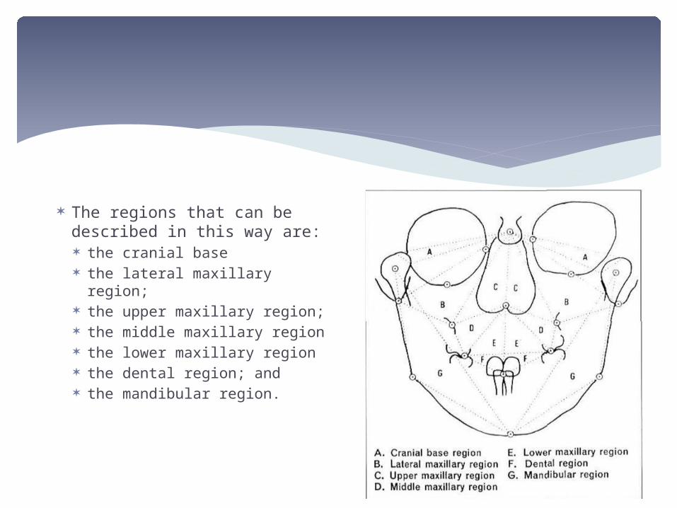
The regions that can be described in this way are: the cranial base the lateral maxillary region; the upper maxillary region; the middle maxillary region the lower maxillary region the dental region; and the mandibular region.
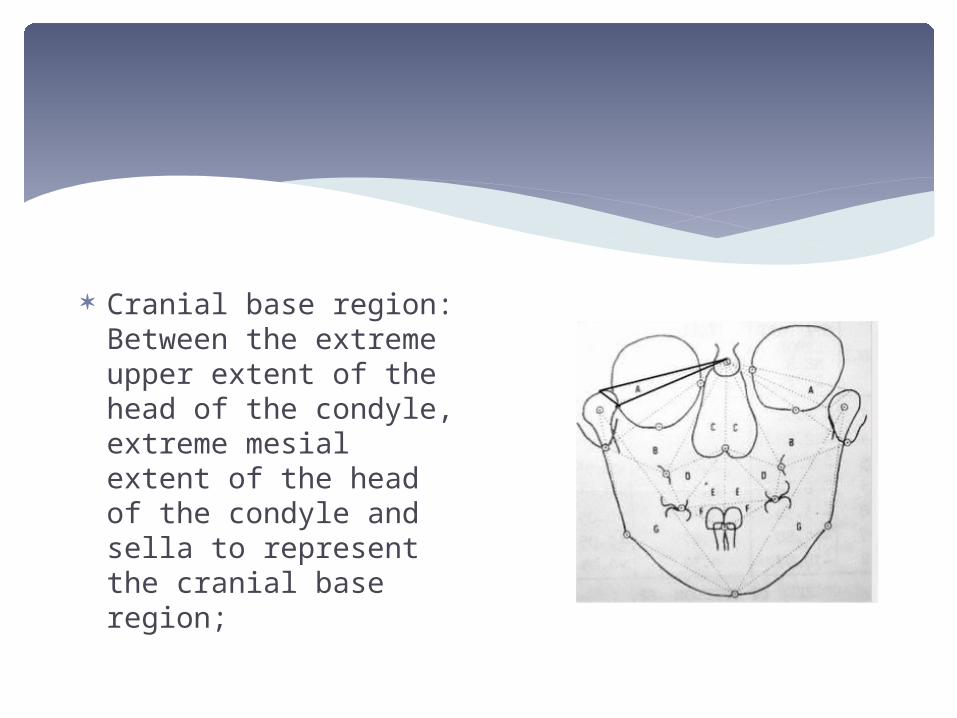
Cranial base region: Between the extreme upper extent of the head of the condyle, extreme mesial extent of the head of the condyle and sella to represent the cranial base region;
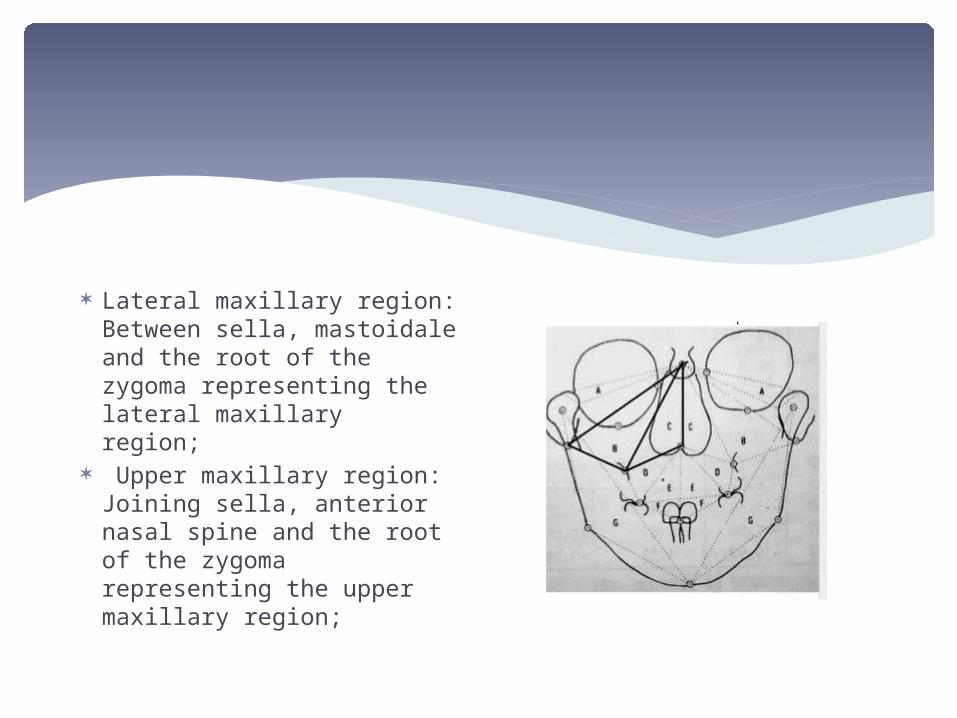
Lateral maxillary region: Between sella, mastoidale and the root of the zygoma representing the lateral maxillary region;
Upper maxillary region: Joining sella, anterior nasal spine and the root of the zygoma representing the upper maxillary region;
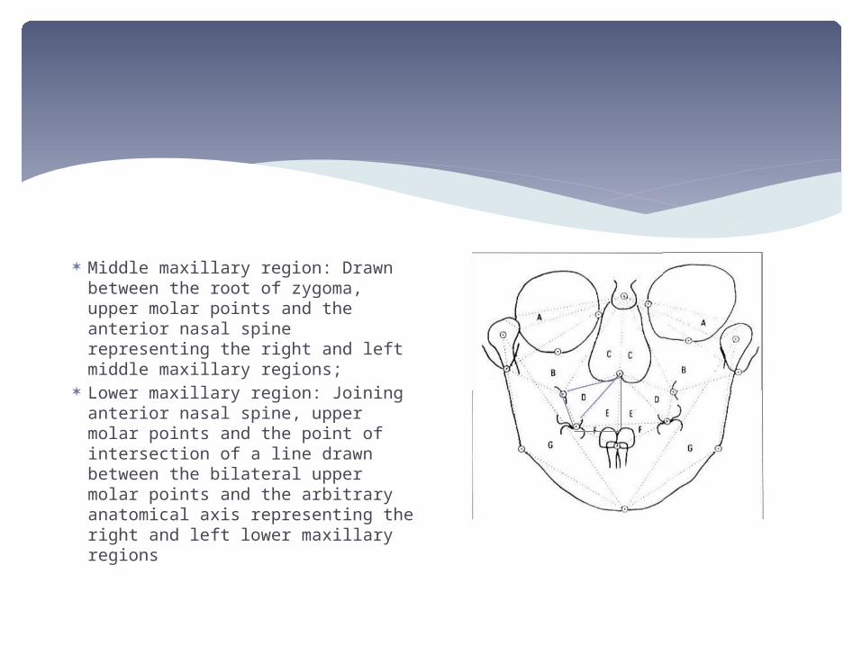
Middle maxillary region: Drawn between the root of zygoma, upper molar points and the anterior nasal spine representing the right and left middle maxillary regions;
Lower maxillary region: Joining anterior nasal spine, upper molar points and the point of intersection of a line drawn between the bilateral upper molar points and the arbitrary anatomical axis representing the right and left lower maxillary regions
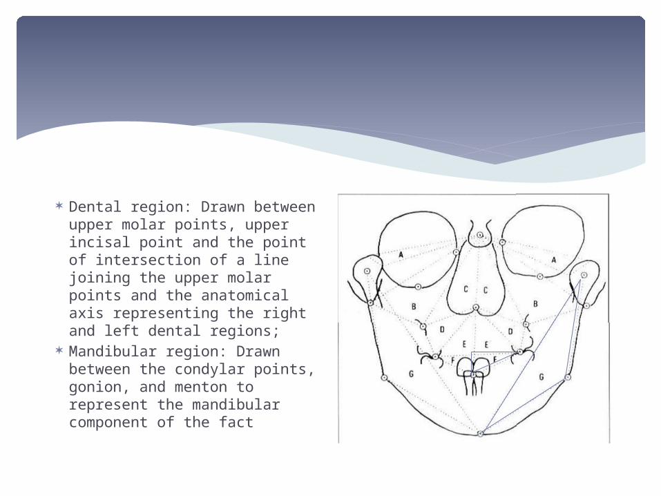
Dental region: Drawn between upper molar points, upper incisal point and the point of intersection of a line joining the upper molar points and the anatomical axis representing the right and left dental regions;
Mandibular region: Drawn between the condylar points, gonion, and menton to represent the mandibular component of the fact
SVANHOLT AND SOLOW ANALYSIS
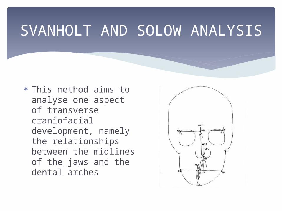
This method aims to analyse one aspect of transverse craniofacial development, namely the relationships between the midlines of the jaws and the dental arches
SVANHOLT AND SOLOW ANALYSIS
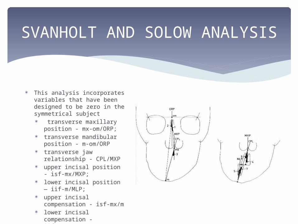
This analysis incorporates variables that have been designed to be zero in the symmetrical subject transverse maxillary
position - mx-om/ORP; transverse mandibular
position - m-om/ORP transverse jaw relationship
- CPL/MXP upper incisal position - isf-
mx/MXP; lower incisal position — iif-
m/MLP; upper incisal compensation
- isf-mx/m lower incisal compensation
- iif-m/mx.
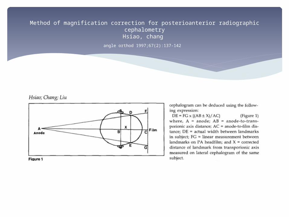
Method of magnification correction for posterioanterior radiographic cephalometryHsiao, chang
angle orthod 1997;67(2):137-142

THANKYOU!