Embed Size (px)
Citation preview
Let�s dig up the advantage of best web hosting with a luxury of virtual private server
alongside dedicated hosting.
Before the advent of the aeroplane, acoustic location was applied to determining the presence and position of ships in fog.
Acoustic location was used from mid-WW1 to the early years of WW2 for the passive detection of aircraft by picking up the noise of the engines. It was rendered obsolete before and during WW2 by the introduction of radar, which was far more effective. Horns give both acoustic gain and directionality; the increased inter-horn spacing compared with human ears increases the observer's ability to localise the direction of a sound.
There were three main kinds of system:
Personal/wearable horns Updated
Transportable steerable horns
Static dishes
Static walls
STEERABLE HORNS: PERSONAL
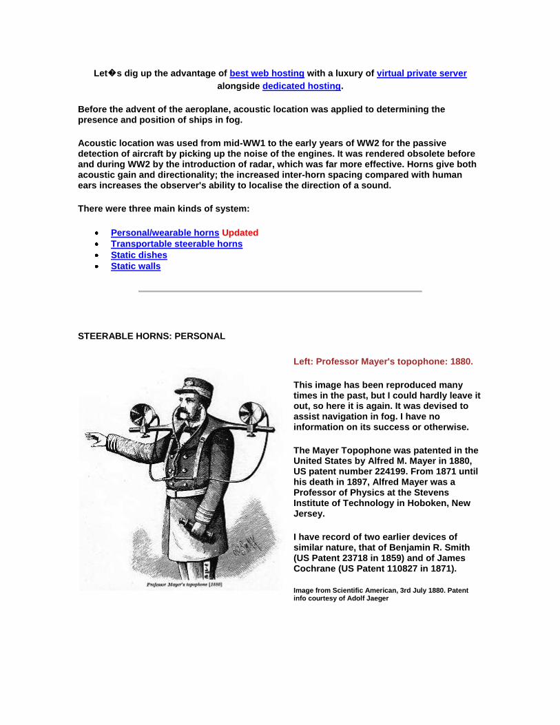
Left: Professor Mayer's topophone: 1880.
This image has been reproduced many times in the past, but I could hardly leave it out, so here it is again. It was devised to assist navigation in fog. I have no information on its success or otherwise.
The Mayer Topophone was patented in the United States by Alfred M. Mayer in 1880, US patent number 224199. From 1871 until his death in 1897, Alfred Mayer was a Professor of Physics at the Stevens Institute of Technology in Hoboken, New Jersey.
I have record of two earlier devices of similar nature, that of Benjamin R. Smith (US Patent 23718 in 1859) and of James Cochrane (US Patent 110827 in 1871).
Image from Scientific American, 3rd July 1880. Patent info courtesy of Adolf Jaeger
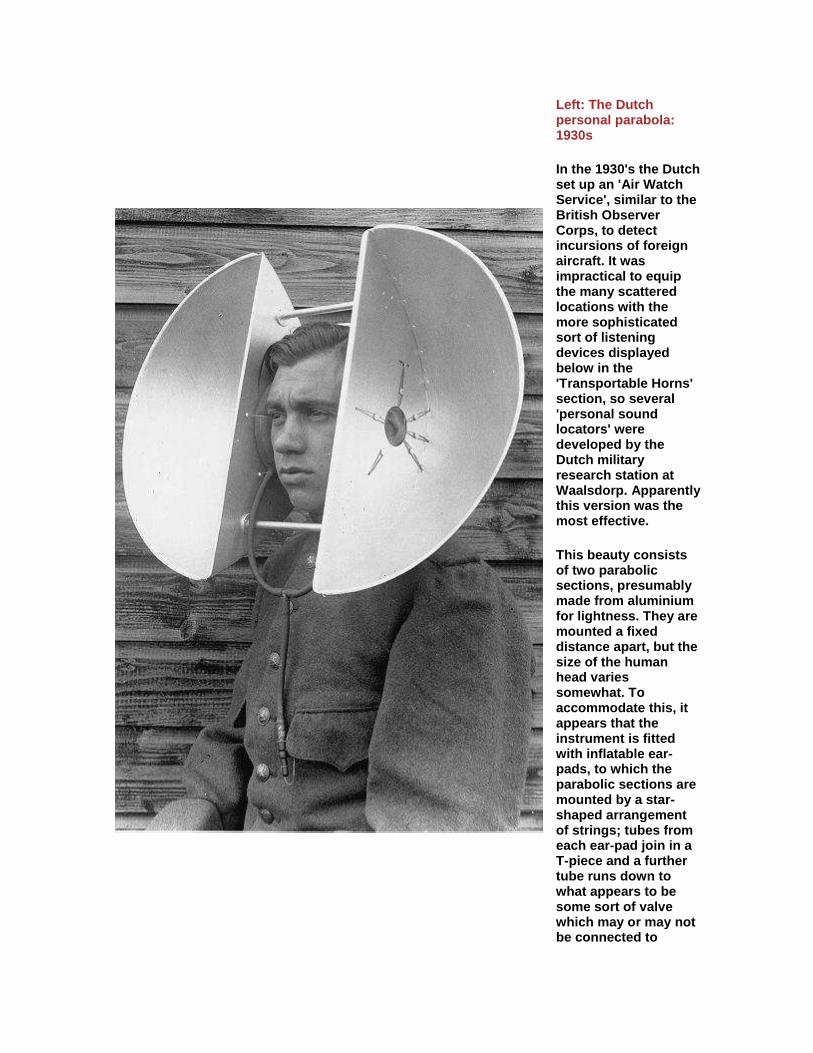
Left: The Dutch personal parabola: 1930s
In the 1930's the Dutch set up an 'Air Watch Service', similar to the British Observer Corps, to detect incursions of foreign aircraft. It was impractical to equip the many scattered locations with the more sophisticated sort of listening devices displayed below in the 'Transportable Horns' section, so several 'personal sound locators' were developed by the Dutch military research station at Waalsdorp. Apparently this version was the most effective.
This beauty consists of two parabolic sections, presumably made from aluminium for lightness. They are mounted a fixed distance apart, but the size of the human head varies somewhat. To accommodate this, it appears that the instrument is fitted with inflatable ear-pads, to which the parabolic sections are mounted by a star-shaped arrangement of strings; tubes from each ear-pad join in a T-piece and a further tube runs down to what appears to be some sort of valve which may or may not be connected to
something in our hero's top pocket. It seems likely that the ear-pads were inflated by mouth. "You can top up your air at any time..." From his pained expression, it looks as if this chap may have overdone the inflation.
According to a report dated 1935, this device was put into at least limited production.
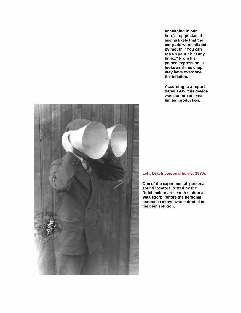
Left: Dutch personal horns: 1930s
One of the experimental 'personal sound locators' tested by the Dutch military research station at Waalsdorp, before the personal parabolas above were adopted as the best solution.
Left: The Shoutophone: date unknown
All the information known is in the text that accompanies the picture. I believe this comes from one of the American science magazines. Probably published in the 1930s, as it is taken for granted that the readers will know what an airplane detector is.
Surely the receiving horns should be pointing directly forwards?
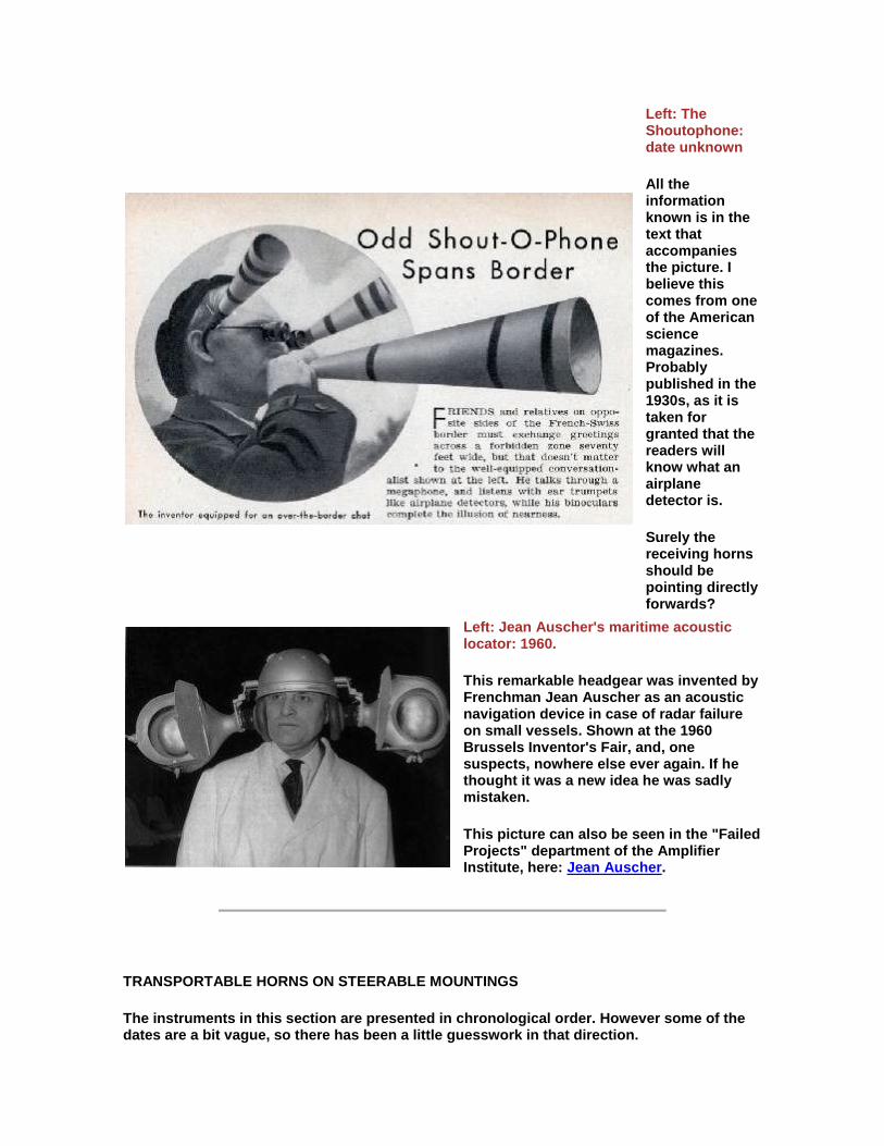
Left: Jean Auscher's maritime acoustic locator: 1960.
This remarkable headgear was invented by Frenchman Jean Auscher as an acoustic navigation device in case of radar failure on small vessels. Shown at the 1960 Brussels Inventor's Fair, and, one suspects, nowhere else ever again. If he thought it was a new idea he was sadly mistaken.
This picture can also be seen in the "Failed Projects" department of the Amplifier Institute, here: Jean Auscher.
TRANSPORTABLE HORNS ON STEERABLE MOUNTINGS
The instruments in this section are presented in chronological order. However some of the dates are a bit vague, so there has been a little guesswork in that direction.
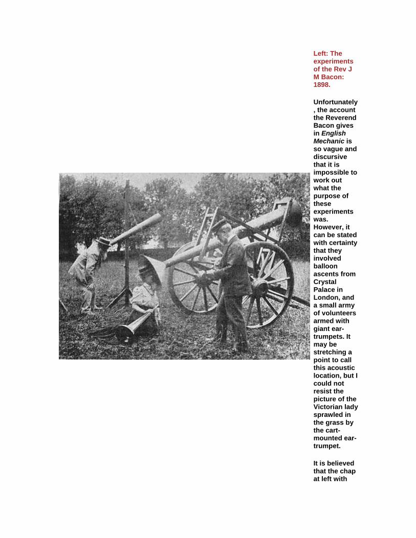
Left: The experiments of the Rev J M Bacon: 1898.
Unfortunately, the account the Reverend Bacon gives in English Mechanic is so vague and discursive that it is impossible to work out what the purpose of these experiments was. However, it can be stated with certainty that they involved balloon ascents from Crystal Palace in London, and a small army of volunteers armed with giant ear-trumpets. It may be stretching a point to call this acoustic location, but I could not resist the picture of the Victorian lady sprawled in the grass by the cart-mounted ear-trumpet.
It is believed that the chap at left with

the long white beard is the Rev John Mackenzie Bacon himself. I must admit that my first thought was that he was some sort of fruitcake, but Wikipedia put me straight; he was a Fellow of the Royal Astronomical Society, and well-respected.
From English Mechanic 30 Sept 1898, p155.
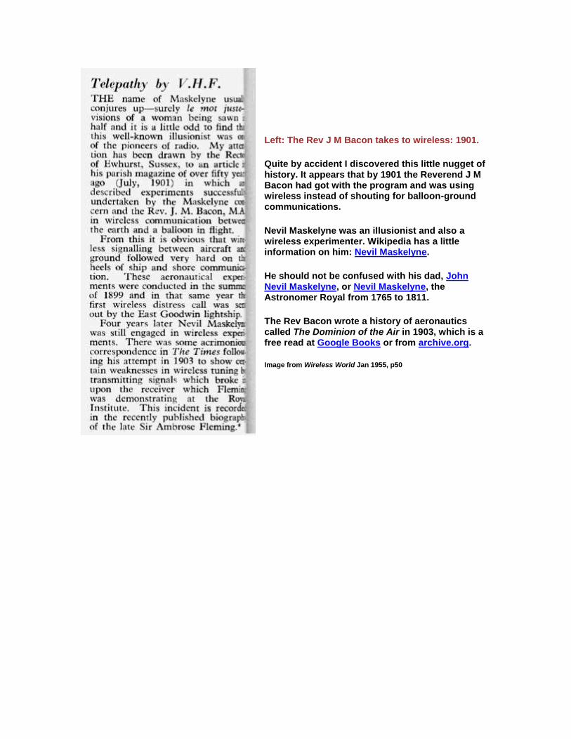
Left: The Rev J M Bacon takes to wireless: 1901.
Quite by accident I discovered this little nugget of history. It appears that by 1901 the Reverend J M Bacon had got with the program and was using wireless instead of shouting for balloon-ground communications.
Nevil Maskelyne was an illusionist and also a wireless experimenter. Wikipedia has a little information on him: Nevil Maskelyne.
He should not be confused with his dad, John Nevil Maskelyne, or Nevil Maskelyne, the Astronomer Royal from 1765 to 1811.
The Rev Bacon wrote a history of aeronautics called The Dominion of the Air in 1903, which is a free read at Google Books or from archive.org.
Image from Wireless World Jan 1955, p50
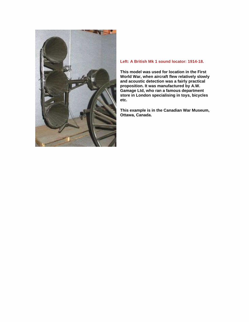
Left: A British Mk 1 sound locator: 1914-18.
This model was used for location in the First World War, when aircraft flew relatively slowly and acoustic detection was a fairly practical proposition. It was manufactured by A.W. Gamage Ltd, who ran a famous department store in London specialising in toys, bicycles etc.
This example is in the Canadian War Museum, Ottawa, Canada.
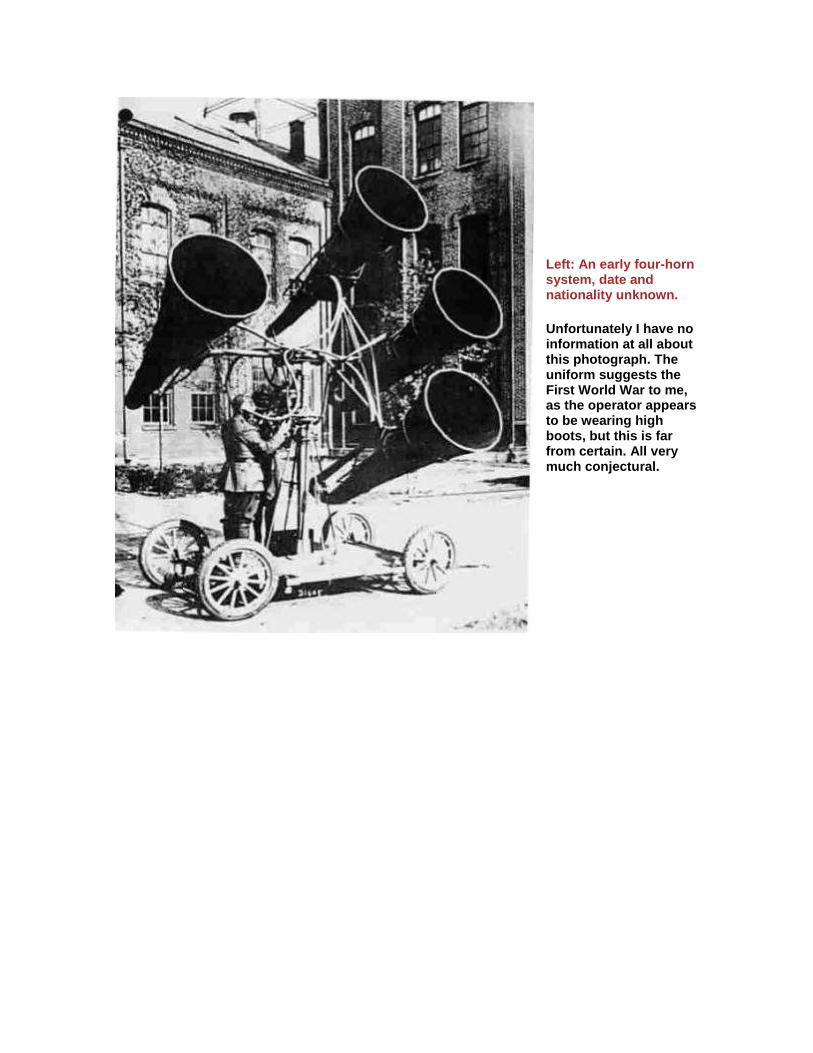
Left: An early four-horn system, date and nationality unknown.
Unfortunately I have no information at all about this photograph. The uniform suggests the First World War to me, as the operator appears to be wearing high boots, but this is far from certain. All very much conjectural.

Above: A two-horn system at Bolling Field, USA, in 1921.
The building in the background is the Army War College at Fort McNair.
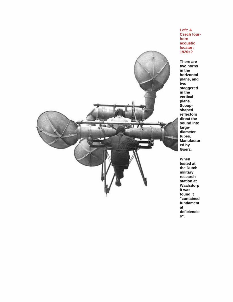
Left: A Czech four-horn acoustic locator: 1920s?
There are two horns in the horizontal plane, and two staggered in the vertical plane. Scoop-shaped reflectors direct the sound into large-diameter tubes. Manufactured by Goerz.
When tested at the Dutch military research station at Waalsdorp it was found it "contained fundamental deficiencies".
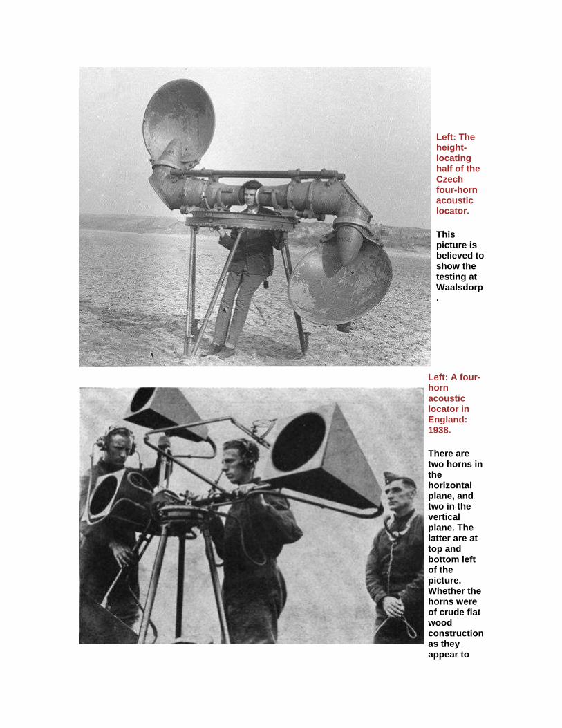
Left: The height-locating half of the Czech four-horn acoustic locator.
This picture is believed to show the testing at Waalsdorp.
Left: A four-horn acoustic locator in England: 1938.
There are two horns in the horizontal plane, and two in the vertical plane. The latter are at top and bottom left of the picture. Whether the horns were of crude flat wood construction as they appear to
be, or if the flat panels were a protective casing for a more conventional horn remains a matter for speculation at present.
This picture appeared in Popular Mechanics for Dec 1938. The caption describes the personnel as being from the Royal Engineers, (part of the British Army) but it seems more likely that they were actually from the Royal Observer Corps, who were civilians; however, the older chap on the right is wearing a distinctly military forage cap. Deep waters, Watson.

Left: A four-horn acoustic locator again, in England: 1930s.
Once more there are three operators, two with stethoscopes linked to pairs of horns for stereo listening. The exact method of operation is currently unknown, but I suspect was as follows: the man on the left adjusts the mounting elevation until the aircraft noise is apparently central, while the chap on the right adjusts the bearing for the same result. The man in the middle reads bearing and elevation from dials and transmits it by telephone to the air defence system where the results from several

locators can be combined to triangulate the target, and give its approximate height and position.
Note that this version is not the same as that above. The two horizontal-plane horns are now on the same side of the tripod.
This picture appeared in a book called Aerial Wonders of Our Time published in Dec 193?. The personnel here are definitely from the Royal Observer Corps. This was a group of civilian volunteers that had its origins in WW1. See: here. (external link)

Left: Acoustic locators in Japan: 1930s.
This remarkable picture may have been reproduced before, but I make no apology for showing it here. The impressive array of Japanese war-tubas belong to at least two acoustic locators mounted on 4-wheel carriages. It is a little difficult to work exactly what is connected to what, not least because the background appears to have been erased by some unsubtle retouching, but I think that the format is the same as the British model; there are two horns in a horizontal plane, and on one side of the
mounting there are two more in a vertical plane.
To the right, one of the figures is the Japanese emperor Horohito. Behind him are the AA guns intended to be used in conjunction with the locators. The only Japanese gun that I have found documented as being used with a sound locator is the Type 88 dual-purpose AA/coast-defence 75mm; there is not enough visible detail to verify that these are the guns shown in the picture, but they look about the right size.
This picture was the subject of a Fark Photoshop
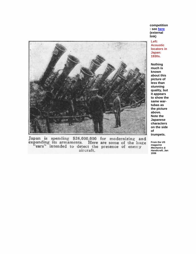
competition: see here (external link)
Left: Acoustic locators in Japan: 1930s.
Nothing much is known about this picture of less than stunning quality, but it appears to show the same war-tubas as the picture above. Note the Japanese characters on the side of trumpets.
From the US magazine Mechanics & Handicraft, Jan 1936

Left: Acoustic locator on trial in France: 1930s.
This remarkable machine is an acoustic locator based on hexagons. Each of the four assemblies carries 36 small hexagonal horns, arranged in six groups of six. Presumably this arrangement was intended to increase the gain or directionality of the instrument.
Once again there are three operators.
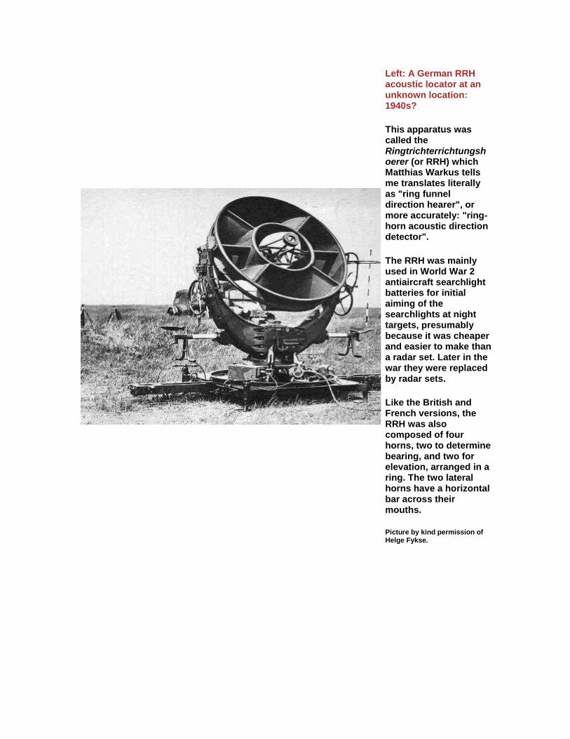
Left: A German RRH acoustic locator at an unknown location: 1940s?
This apparatus was called the Ringtrichterrichtungshoerer (or RRH) which Matthias Warkus tells me translates literally as "ring funnel direction hearer", or more accurately: "ring-horn acoustic direction detector".
The RRH was mainly used in World War 2 antiaircraft searchlight batteries for initial aiming of the searchlights at night targets, presumably because it was cheaper and easier to make than a radar set. Later in the war they were replaced by radar sets.
Like the British and French versions, the RRH was also composed of four horns, two to determine bearing, and two for elevation, arranged in a ring. The two lateral horns have a horizontal bar across their mouths.
Picture by kind permission of Helge Fykse.
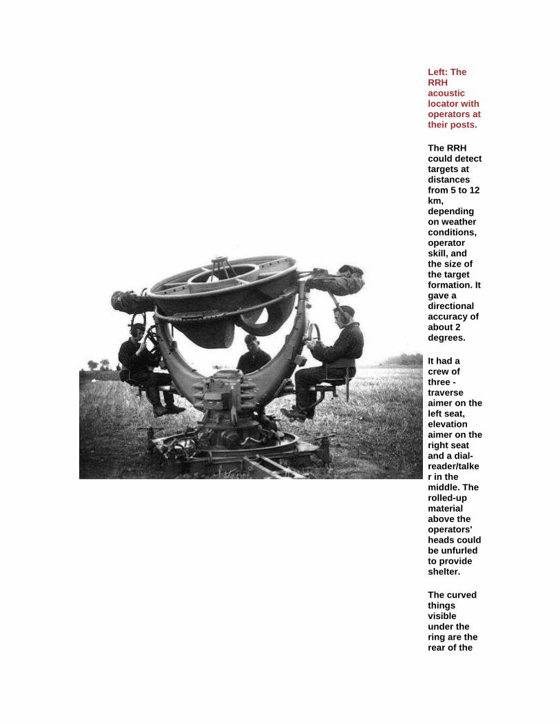
Left: The RRH acoustic locator with operators at their posts.
The RRH could detect targets at distances from 5 to 12 km, depending on weather conditions, operator skill, and the size of the target formation. It gave a directional accuracy of about 2 degrees.
It had a crew of three - traverse aimer on the left seat, elevation aimer on the right seat and a dial-reader/talker in the middle. The rolled-up material above the operators' heads could be unfurled to provide shelter.
The curved things visible under the ring are the rear of the
horns.
Picture by kind permission of Helge Fykse.
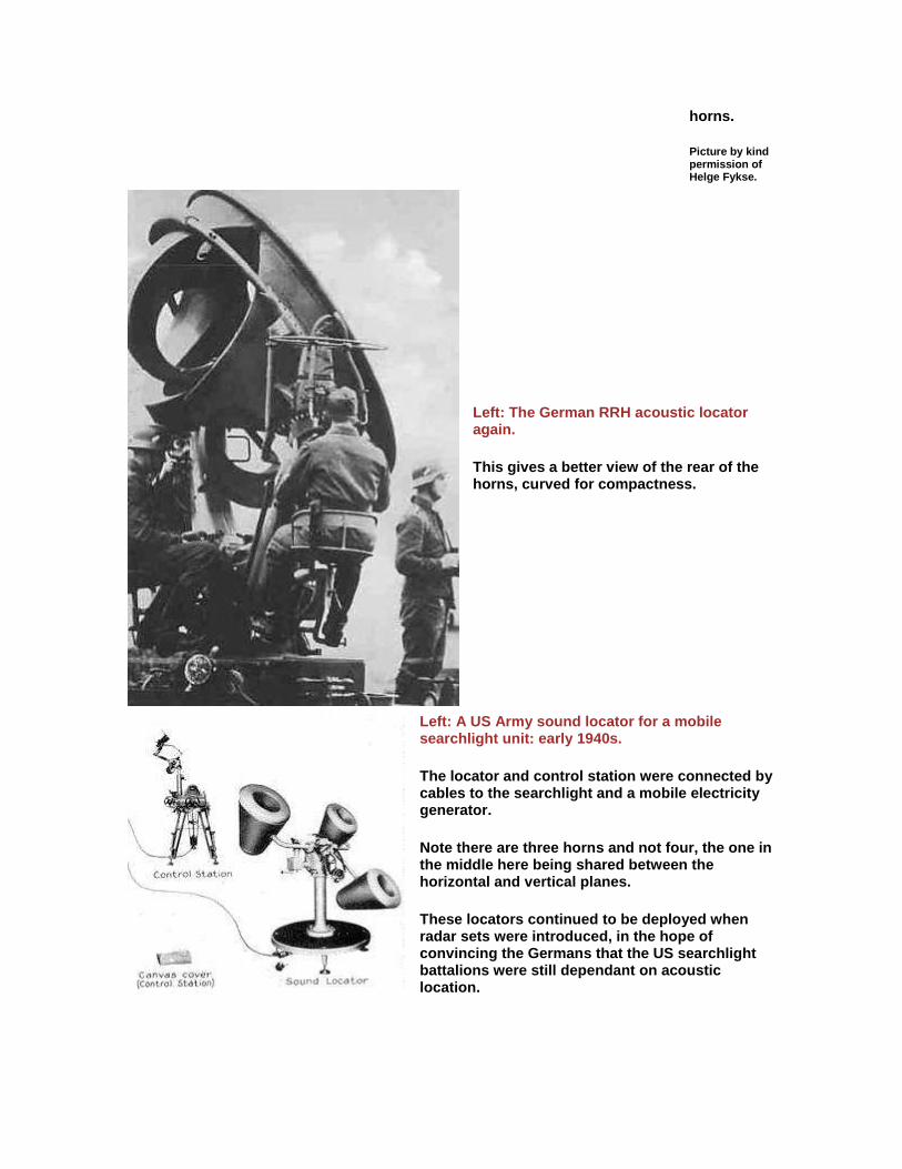
Left: The German RRH acoustic locator again.
This gives a better view of the rear of the horns, curved for compactness.
Left: A US Army sound locator for a mobile searchlight unit: early 1940s.
The locator and control station were connected by cables to the searchlight and a mobile electricity generator.
Note there are three horns and not four, the one in the middle here being shared between the horizontal and vertical planes.
These locators continued to be deployed when radar sets were introduced, in the hope of convincing the Germans that the US searchlight battalions were still dependant on acoustic location.
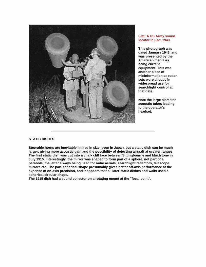
Left: A US Army sound locator in use: 1943.
This photograph was dated January 1943, and was presented by the American media as being current equipment. This was another piece of misinformation as radar sets were already in widespread use for searchlight control at that date.
Note the large diameter acoustic tubes leading to the operator's headset.
STATIC DISHES
Steerable horns are inevitably limited in size, even in Japan, but a static dish can be much larger, giving more acoustic gain and the possibility of detecting aircraft at greater ranges. The first static dish was cut into a chalk cliff face between Sittingbourne and Maidstone in July 1915. Interestingly, the mirror was shaped to form part of a sphere, not part of a parabola, the latter always being used for radio aerials, searchlight reflectors, telescope mirrors etc. The part-spherical shape presumably gives better off-axis performance at the expense of on-axis precision, and it appears that all later static dishes and walls used a spherical/circular shape. The 1915 dish had a sound collector on a rotating mount at the "focal point".
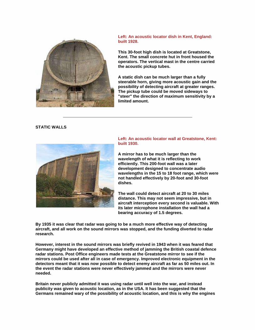
Left: An acoustic locator dish in Kent, England: built 1928.
This 30-foot high dish is located at Greatstone, Kent. The small concrete hut in front housed the operators. The vertical mast in the centre carried the acoustic pickup tubes.
A static dish can be much larger than a fully steerable horn, giving more acoustic gain and the possibility of detecting aircraft at greater ranges. The pickup tube could be moved sideways to "steer" the direction of maximum sensitivity by a limited amount.
STATIC WALLS
Left: An acoustic locator wall at Greatstone, Kent: built 1930.
A mirror has to be much larger than the wavelength of what it is reflecting to work efficiently. This 200-foot wall was a later development designed to concentrate audio wavelengths in the 15 to 18 foot range, which were not handled effectively by 20-foot and 30-foot dishes.
The wall could detect aircraft at 20 to 30 miles distance. This may not seem impressive, but in aircraft interception every second is valuable. With its later microphone installation the wall had a bearing accuracy of 1.5 degrees.
By 1935 it was clear that radar was going to be a much more effective way of detecting aircraft, and all work on the sound mirrors was stopped, and the funding diverted to radar research.
However, interest in the sound mirrors was briefly revived in 1943 when it was feared that Germany might have developed an effective method of jamming the British coastal defence radar stations. Post Office engineers made tests at the Greatstone mirror to see if the mirrors could be used after all in case of emergency. Improved electronic equipment in the detectors meant that it was now possible to detect enemy aircraft as far as 50 miles out. In the event the radar stations were never effectively jammed and the mirrors were never needed.
Britain never publicly admitted it was using radar until well into the war, and instead publicity was given to acoustic location, as in the USA. It has been suggested that the Germans remained wary of the possibility of acoustic location, and this is why the engines

of their heavy bombers were run unsynchronised, instead of synchronised (as was the usual practice, to reduce vibration) in the hope that this would make detection more difficult.
HISTORICAL NOTES
The first Japanese attack on the fortress island of Corregidor (in the Phillipines) on 29th December 1941 was detected by American acoustic locators.


![Radares b[1]](https://img.pdfslide.net/doc/110x75/55b46d55bb61eb3a3f8b4786/radares-b1.jpg)


![Radares a[1]](https://img.pdfslide.net/doc/110x75/55b17e2cbb61ebe8098b459e/radares-a1.jpg)