Embed Size (px)
Citation preview

SIMULATIONS LCC RESONANT CIRCUIT
564: POWER ELECTRONICS III
COLORADO STATE UNIVERSITY
By Electrical and Computer Engineering student
Minh Anh Thi Nguyen
Page 1 of 18

PURPOSE: The purpose of this lab is to simulate the LCC circuit using
MATLAB to better familiarize the student with some of its operating
characteristics. This lab will explore some of the following aspects of the buck
converter:
Input impedance
Output impedance
Zero frequency
Output power
Output current
Output voltage
Zero poles
Phase of transfer function
Stable circuit
Unstable circuit
NOTE: The simulations that follow are intended to be completed with MATLAB.
It is assumed that the student has a fundamental understanding of the operation
of MATLAB. MATLAB provides tutorials for users that are not experienced with
its functions.
PROCEDURE:
Part 1: write an m file shown in Figure 1.
Vm is a variable voltage. Set to 1 voltsL is a variable inductor. Set to 25H.
R is a variable ideal resistor. Set to 25.
Cp is a variable ideal capacitor. Change the value to 66nF.
Cs is a variable ideal capacitor. Change the value to 200nF.
Page 2 of 18

Figure 1. Input impedance for LCC circuit
Page 3 of 18

Once the above m file is captured, the simulations can be run. First, go to your
directory. Find your m file and then run your file. If there is a red message on
your MATLAB window, then you need to correct your error. Otherwise, you will
see the solution as show in figure 2.
Page 4 of 18

Figure 2. The output of Zinput_LCC m file.
Next, plot the output voltage of the LCC circuit. By adding the output voltage
equation to the LCC m file. Then rerun the LCC m file.
Page 5 of 18

Page 6 of 18

Now plot the inductor current of the LCC circuit. By adding the inductor current
equations to the LCC m file. Then rerun the LCC m file.
Page 7 of 18

Page 8 of 18

Page 9 of 18
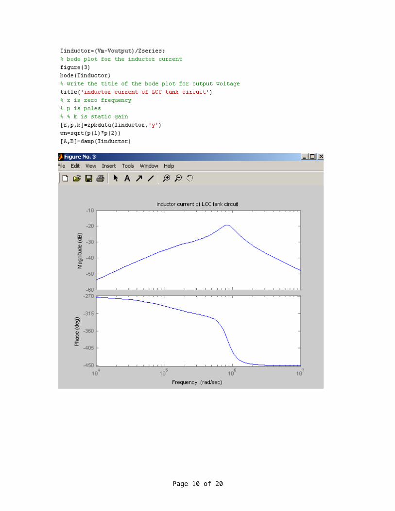
Now find the zero crossing of phase of inductor current. First define the input
impedance as a vector. Write a loop function to do the zero crossing of the
phase. Then rerun the simulation. If there is any error message on your
MATLAB windows, then correct your error and then rerun the simulation.
Otherwise, you will see the result as show below
Page 10 of 18

Page 11 of 18
Now calculate and plot the output of capacitor current. By adding the capacitor
current equations to the LCC m file. Then rerun the LCC m file. Then rerun the
simulation. If there is any error message on your MATLAB windows, then
correct your error and then rerun the simulation. Otherwise, you will see the
results as show below
Page 12 of 18

Page 13 of 18

Page 14 of 18

Now calculate and plot the output power of LCC circuit. By adding the output
power equations to the LCC m file. But the output power is a vector function.
First define the input impedance as a vector. Write a loop function to do the zero
crossing of the phase. Then rerun the LCC m file. If there is any error message
on your MATLAB windows, then correct your error and then rerun the simulation.
Otherwise, you will see the results as show below
Page 15 of 18

Page 16 of 18

ans =
0.1769
Page 17 of 18

Page 18 of 18