Embed Size (px)
Citation preview

Chapter (2) Simple Resistive Circuits
- 30 - D r . E l s a y e d E m a r a h
Problems of Chapter 2
Problem 2.1
A bar of silicon is 4 cm long with a circular cross section. If the resistance of the bar
is 40 ohm at room temperature, What is the cross-sectional radius of the bar? For
Silicon 𝜌 = 6.4𝑥102 Ω-m.
Problem 2.2
Use KCL to obtain currents i1, i2, and i3 in the circuit shown in Fig. 1
Solution
Problem 2.3
In the circuit of problem 2.4, obtain v1, v2, and v3.

Chapter (2) Simple Resistive Circuits
- 31 - D r . E l s a y e d E m a r a h
Solution
Problem 2.4
For the circuit shown in figure, Use KVL to Calculate V1, V2, V3, V4, and V5
Problem 2.5
Calculate v and ix in the circuit
shown.
Problem 2.6

Chapter (2) Simple Resistive Circuits
- 32 - D r . E l s a y e d E m a r a h
In the circuit shown in Figure,
(a) Determine the voltage vx.
(b) Determine the power absorbed by the 12 ohm resistor.
Problem 2.7
Using series/parallel resistance combination,
(a) Find the equivalent resistance seen by the source in the circuit.
(b) Find the overall dissipated power.
Example 2.8
The voltage and current were measured at the terminals of the device shown in
Figure (a). The results are tabulated in Figure (b).
(a) Construct a circuit model for this device using an ideal current source
and a resistor.
(b) Use the model to predict the amount of power the device will deliver
to a 5 Ω resistor.

Chapter (2) Simple Resistive Circuits
- 33 - D r . E l s a y e d E m a r a h
𝒗𝒕 (V) 𝒊𝒕(A)
100 0
180 4
260 8
340 12
420 16
(b) (a)
Solution

Chapter (2) Simple Resistive Circuits
- 34 - D r . E l s a y e d E m a r a h
Problem 2.9
Obtain the equivalent resistance at the terminals a-b for each of the circuits
Solution

Chapter (2) Simple Resistive Circuits
- 35 - D r . E l s a y e d E m a r a h
(a)
(b)

Chapter (2) Simple Resistive Circuits
- 36 - D r . E l s a y e d E m a r a h
Problem 2.10
In the circuit in Figure (a) the device labeled D represents a component that has
the equivalent circuit shown in Figure (b). The labels on the terminals of D show
how the device is connected to the circuit.
Find 𝒗𝒙 and the power absorbed by the device.
Solution

Chapter (2) Simple Resistive Circuits
- 37 - D r . E l s a y e d E m a r a h
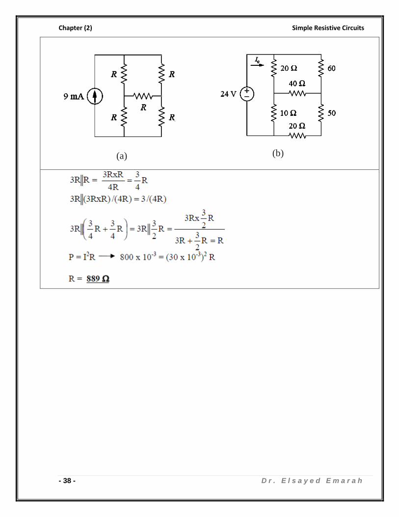
Problem 2.11
1. What value of R in the circuit shown in figure (a) would cause the current
source to deliver 30 watt to the resistors.
2. Calculate Io in the circuit of figure (b).
Chapter (2) Simple Resistive Circuits
- 38 - D r . E l s a y e d E m a r a h
(a)
(b)

Chapter (2) Simple Resistive Circuits
- 39 - D r . E l s a y e d E m a r a h
Problem 2.12
The voltage across the 15 k-Ω resistor in the circuit in Figure is 500 V positive at the
upper terminal.
a) Find the power dissipated in each resistor.
b) Find the power supplied by the 100 mA ideal current source,
c) Verify that the power supplied equals the total power dissipated.
Solution

Chapter (2) Simple Resistive Circuits
- 40 - D r . E l s a y e d E m a r a h

Chapter (2) Simple Resistive Circuits
- 41 - D r . E l s a y e d E m a r a h
Problem 2.13
The variable resistor R in rhe circuir in Figure is adjusted until va equals 60 V Find
the value of R. hint: use KVL and KCL
Solution

Chapter (2) Simple Resistive Circuits
- 42 - D r . E l s a y e d E m a r a h
Problem 2.14
The currents 𝑖𝑎 and ib in the circuil in Figure are 4 A and 2 A, respectively.
i. Fitrd 𝒊𝒈.
ii. Find the power dissipated in each resistor.
iii. Find 𝒗𝒈.
iv. Show that the power delivered by the current source is equal to the power
absorbed by all the other elements.
Solution

Chapter (2) Simple Resistive Circuits
- 43 - D r . E l s a y e d E m a r a h
Chapter (2) Simple Resistive Circuits
- 44 - D r . E l s a y e d E m a r a h
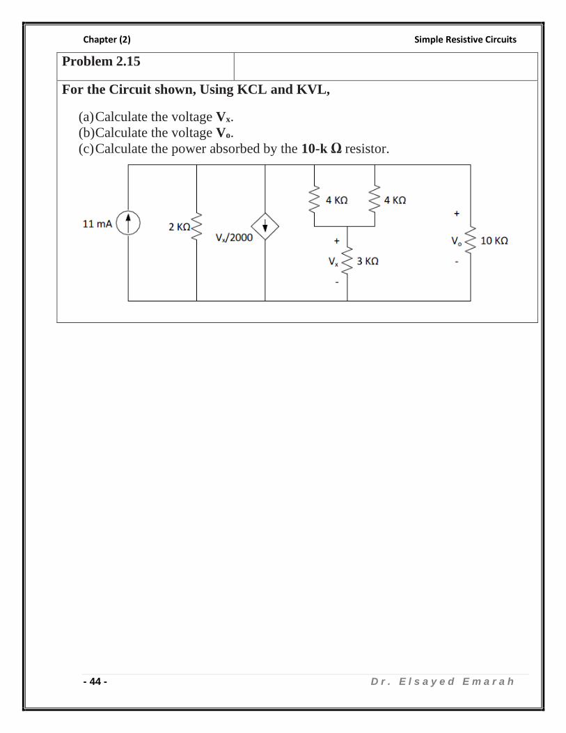
Problem 2.15
For the Circuit shown, Using KCL and KVL,
(a) Calculate the voltage Vx.
(b) Calculate the voltage Vo.
(c) Calculate the power absorbed by the 10-k Ω resistor.

Chapter (2) Simple Resistive Circuits
- 45 - D r . E l s a y e d E m a r a h

Chapter (2) Simple Resistive Circuits
- 46 - D r . E l s a y e d E m a r a h