Embed Size (px)
Citation preview
8.1
Chapter 8
SwitchingModified by Allam AbuMwais
8.2
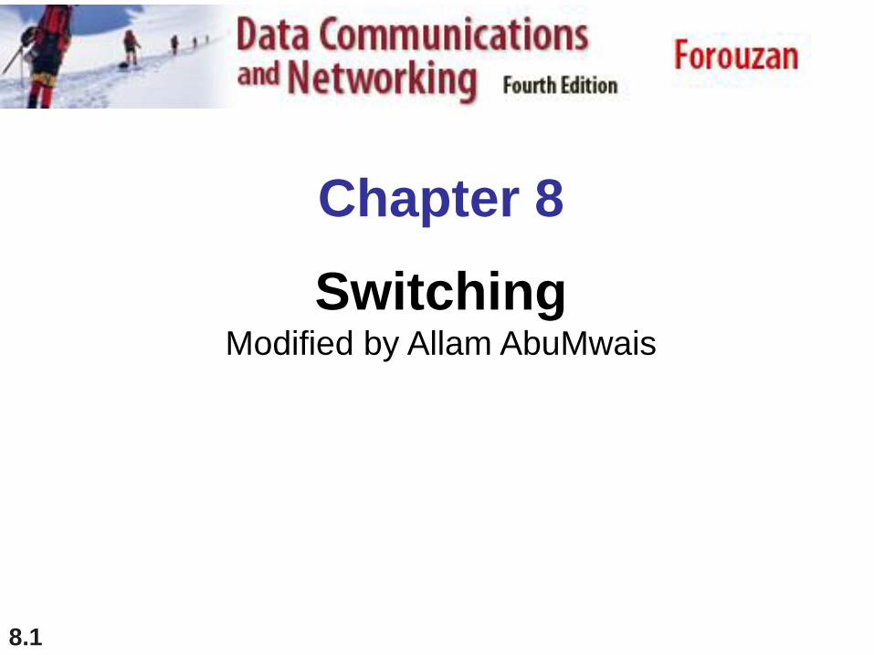
Introduction
Whenever we have multiple devices, we have the
problem of how to connect them to make one-to-one
communication possible.
Mesh network (point-point) and Star network (to
central device) connection. But these impractical in large
networks.
A better solution is switching. A switched network
consists of a series of interlinked nodes, called switches.
Switches are devices capable of creating temporary
connections between two or more devices linked to the
switch.

8.3
Figure 8.1 Switched network
8.4
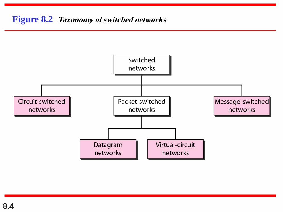
Figure 8.2 Taxonomy of switched networks

8.5
8-1 CIRCUIT-SWITCHED NETWORKS
A circuit-switched network consists of a set of
switches connected by physical links. A connection
between two stations is a dedicated path made of one
or more links. However, each connection uses only
one dedicated channel on each link. Each link is
normally divided into n channels by using FDM or
TDM.
Three Phases
Efficiency
Delay
Circuit-Switched Technology in Telephone Networks
Topics discussed in this section:
8.6
A circuit-switched network is made of a
set of switches connected by physical
links, in which each link is
divided into n channels.
Note
8.7
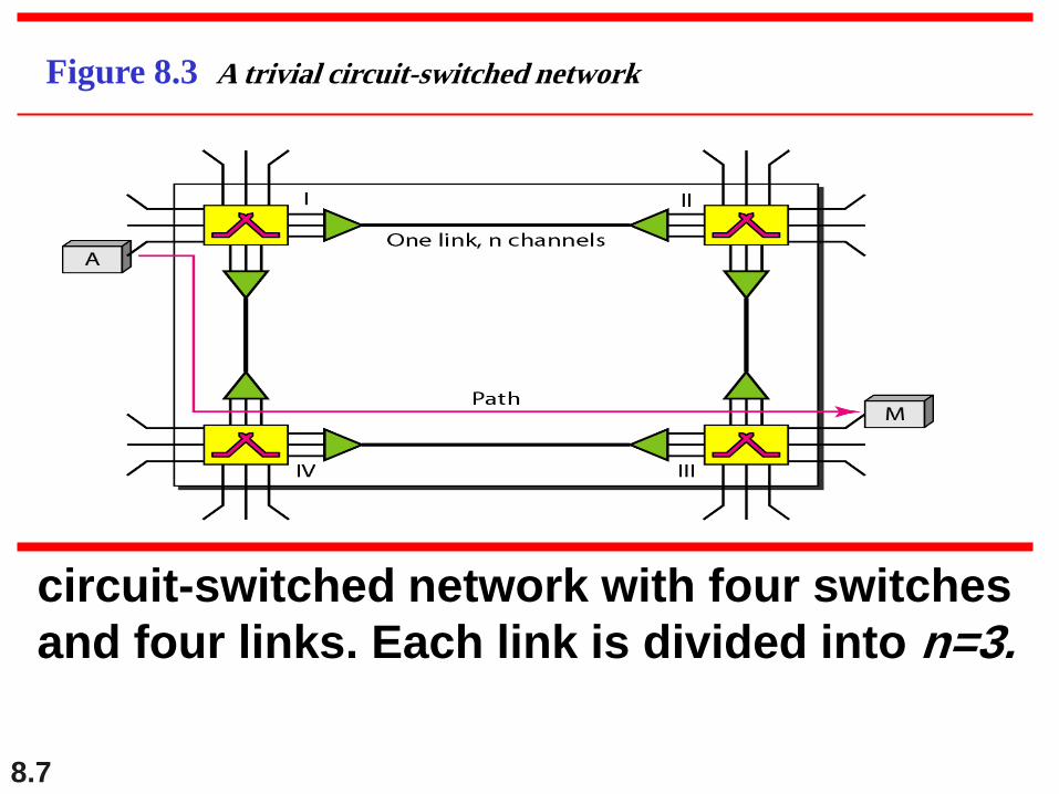
Figure 8.3 A trivial circuit-switched network
circuit-switched network with four switches
and four links. Each link is divided into n=3.
8.8
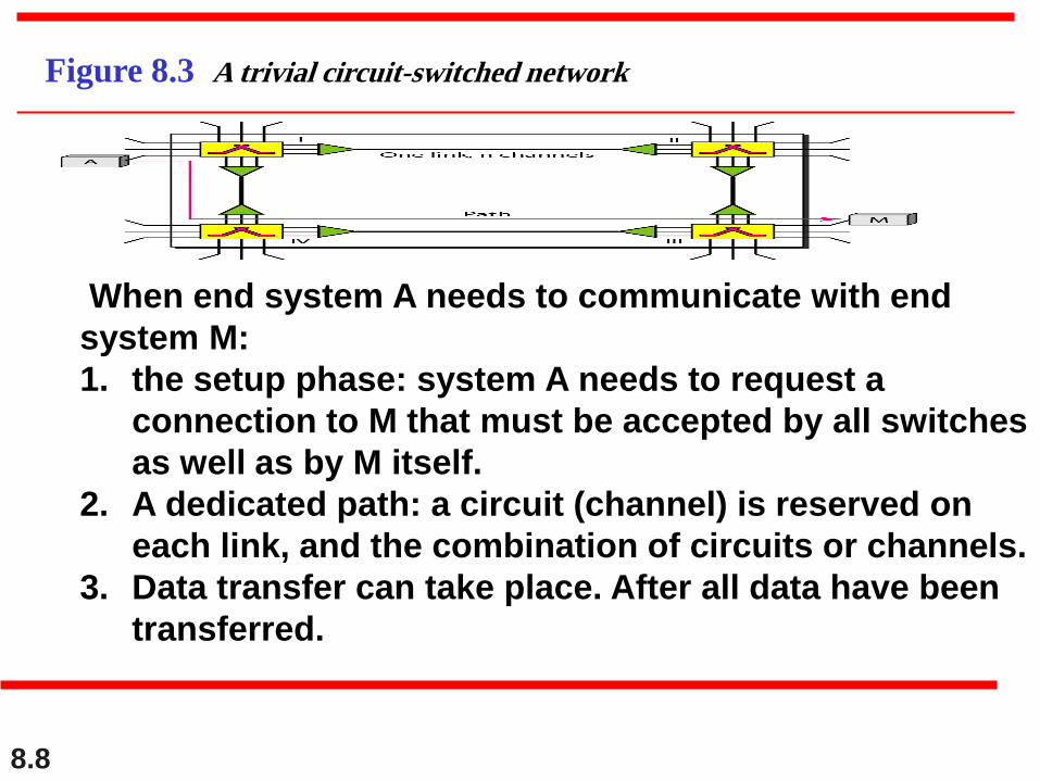
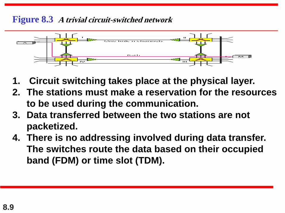
Figure 8.3 A trivial circuit-switched network
When end system A needs to communicate with end
system M:
1. the setup phase: system A needs to request a
connection to M that must be accepted by all switches
as well as by M itself.
2. A dedicated path: a circuit (channel) is reserved on
each link, and the combination of circuits or channels.
3. Data transfer can take place. After all data have been
transferred.
8.9
Figure 8.3 A trivial circuit-switched network
1. Circuit switching takes place at the physical layer.
2. The stations must make a reservation for the resources
to be used during the communication.
3. Data transferred between the two stations are not
packetized.
4. There is no addressing involved during data transfer.
The switches route the data based on their occupied
band (FDM) or time slot (TDM).

8.10
In circuit switching, the resources need
to be reserved during the setup phase;
the resources remain dedicated for the
entire duration of data transfer until the
teardown phase.
Note

8.11
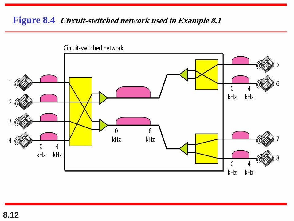
As a trivial example, let us use a circuit-switched
network to connect eight telephones in a small area.
Communication is through 4-kHz voice channels. We
assume that each link uses FDM to connect a maximum
of two voice channels. The bandwidth of each link is
then 8 kHz. Figure 8.4 shows the situation.
Telephone 1 is connected to telephone 7; 2 to 5; 3 to 8;
and 4 to 6. Of course the situation may change when
new connections are made. The switch controls the
connections.
Example 8.1
8.12
Figure 8.4 Circuit-switched network used in Example 8.1
8.13
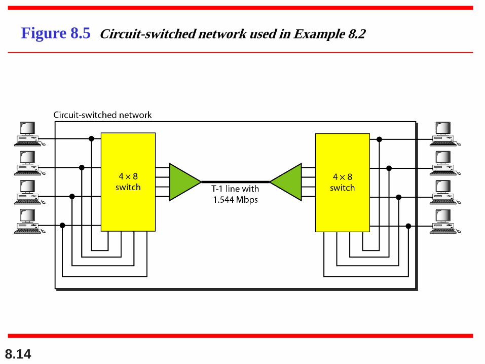
As another example, consider a circuit-switched
network that connects computers in two remote offices
of a private company. The offices are connected using a
T-1 line leased from a communication service provider.
There are two 4 × 8 (4 inputs and 8 outputs) switches in
this network. For each switch, four output ports are
folded into the input ports to allow communication
between computers in the same office. Four other
output ports allow communication between the two
offices. Figure 8.5 shows the situation.
Example 8.2
8.14
Figure 8.5 Circuit-switched network used in Example 8.2
8.15
3 phases:
1. Setup Phase2. Data Transfer Phase3. Teardown Phase
Note
8.16
Efficiency
It can be argued that circuit-switched
networks are not as efficient as the other
two types of networks because resources
are allocated during the entire duration of
the connection.
8.17
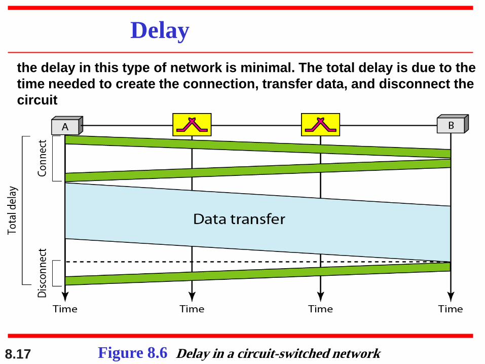
Delay
Figure 8.6 Delay in a circuit-switched network
the delay in this type of network is minimal. The total delay is due to the
time needed to create the connection, transfer data, and disconnect the
circuit
8.18
Switching at the physical layer in the
traditional telephone network uses
the circuit-switching approach.
Note
8.19
8-2 DATAGRAM NETWORKS
1. In data communications, we need to send messages from one
end system to another. If the message is going to pass
through a packet-switched network, it needs to be divided
into packets of fixed or variable size. The size of the packet is
determined by the network and the governing protocol.
2. In a datagram network, each packet is treated independently
of all others.
3. Datagram switching is normally done at the network layer.
Routing Table
Efficiency
Delay
Datagram Networks in the Internet
Topics discussed in this section:
8.20
In a packet-switched network, there
is no resource reservation;
resources are allocated on demand.
Note
8.21
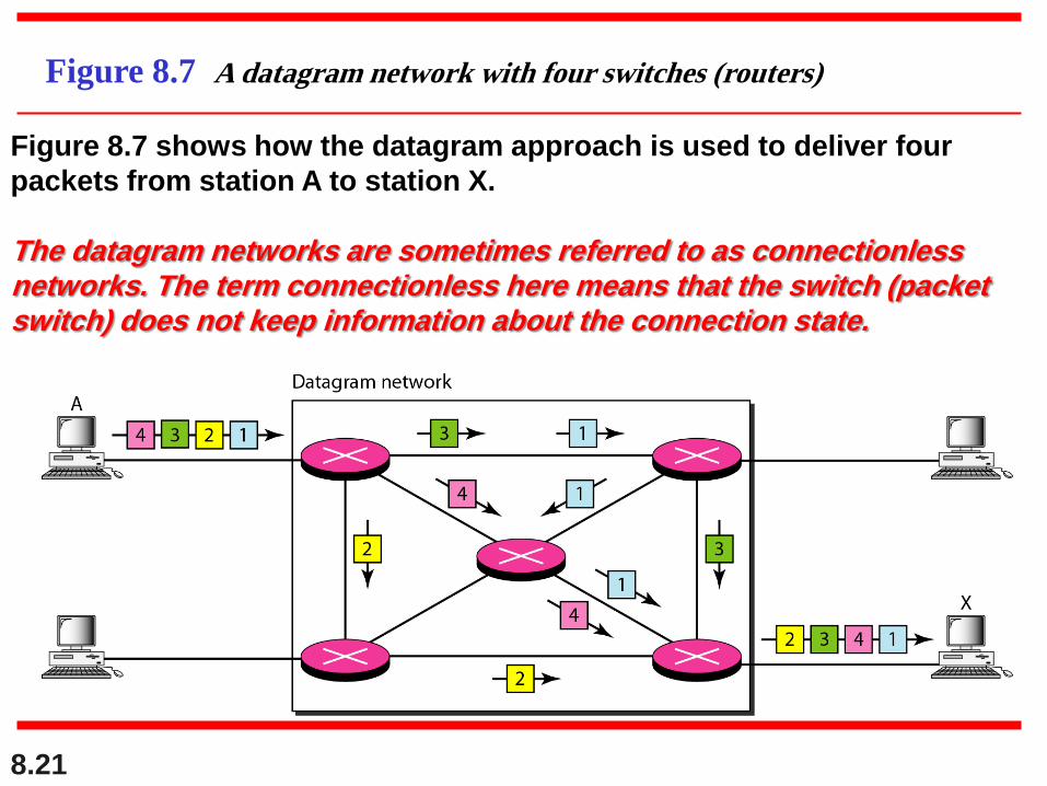
Figure 8.7 A datagram network with four switches (routers)
Figure 8.7 shows how the datagram approach is used to deliver four
packets from station A to station X.
The datagram networks are sometimes referred to as connectionless networks. The term connectionless here means that the switch (packet switch) does not keep information about the connection state.
8.22
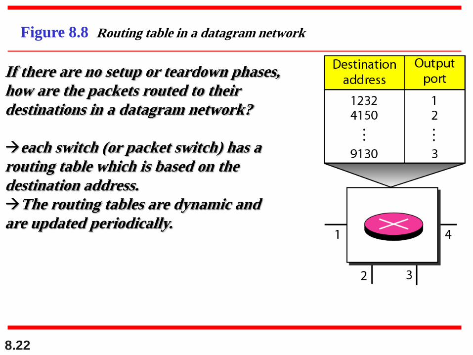
Figure 8.8 Routing table in a datagram network
If there are no setup or teardown phases,
how are the packets routed to their
destinations in a datagram network?
each switch (or packet switch) has a
routing table which is based on the
destination address.
The routing tables are dynamic and
are updated periodically.
8.23
A switch in a datagram network uses a
routing table that is based on the
destination address.
Note
8.24
The destination address in the header of
a packet in a datagram network remains
the same during the entire journey of the
packet.
Note
8.25
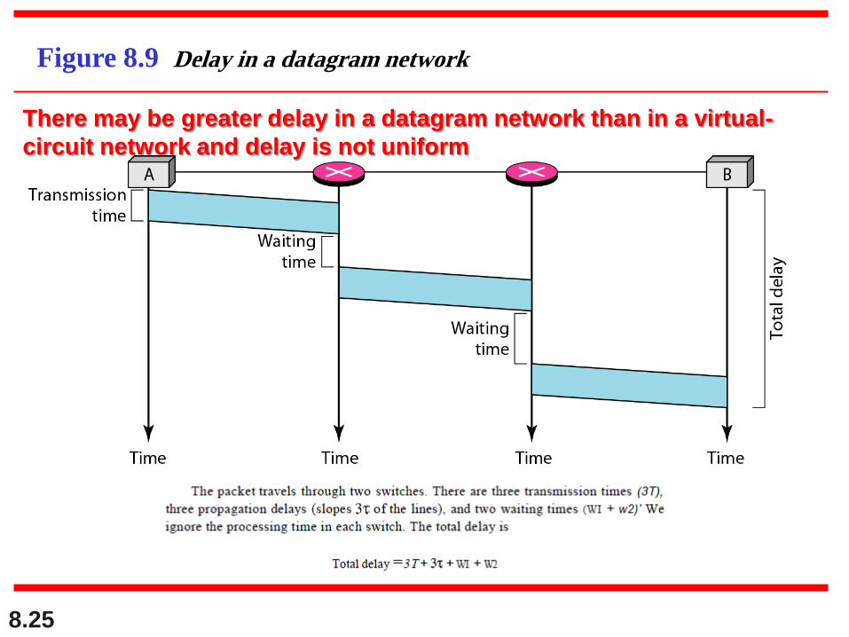
Figure 8.9 Delay in a datagram network
There may be greater delay in a datagram network than in a virtual-
circuit network and delay is not uniform
8.26
Switching in the Internet is done by
using the datagram approach to packet
switching at the network layer.
Note
Datagram Networks in the Internet
8.27
8-3 VIRTUAL-CIRCUIT NETWORKS
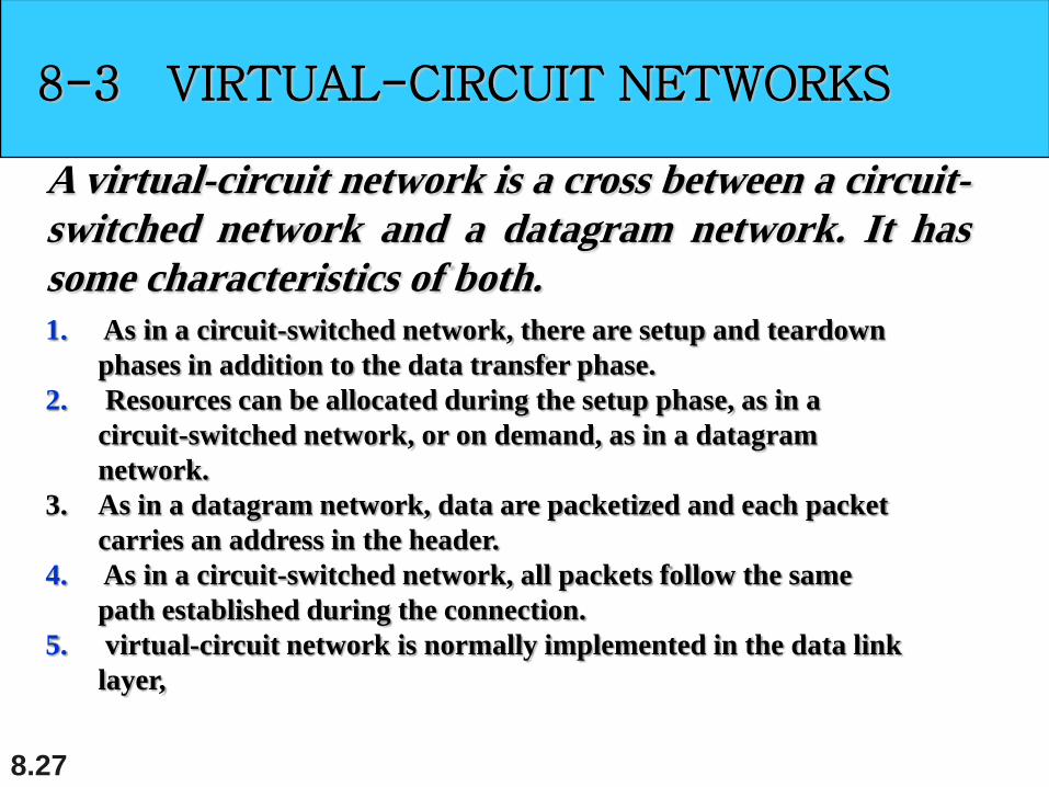
A virtual-circuit network is a cross between a circuit-
switched network and a datagram network. It has
some characteristics of both.
1. As in a circuit-switched network, there are setup and teardown
phases in addition to the data transfer phase.
2. Resources can be allocated during the setup phase, as in a
circuit-switched network, or on demand, as in a datagram
network.
3. As in a datagram network, data are packetized and each packet
carries an address in the header.
4. As in a circuit-switched network, all packets follow the same
path established during the connection.
5. virtual-circuit network is normally implemented in the data link
layer,
8.28
8-3 VIRTUAL-CIRCUIT NETWORKS
Addressing
Three Phases
Efficiency
Delay
Circuit-Switched Technology in WANs
Topics discussed in this section:
8.29
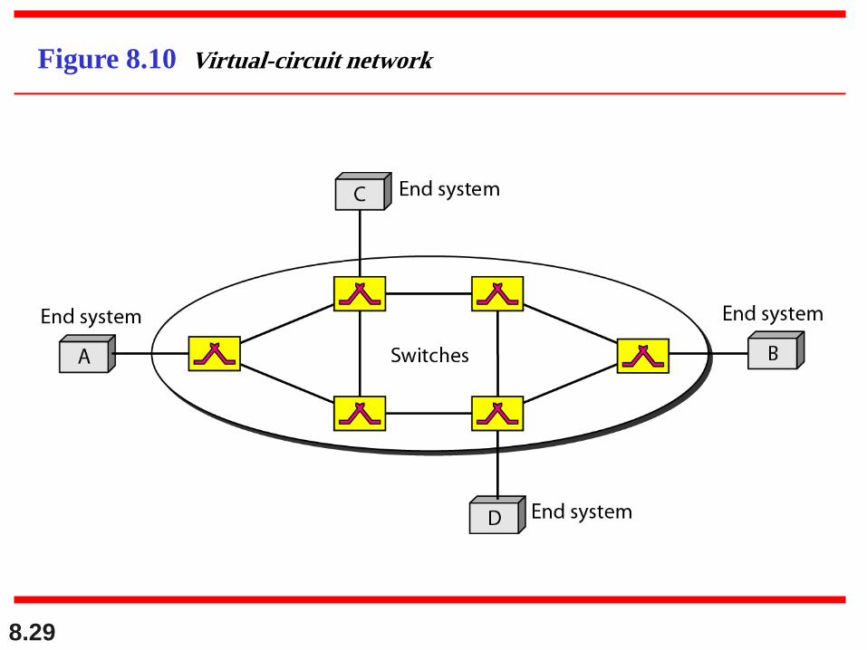
Figure 8.10 Virtual-circuit network
8.30
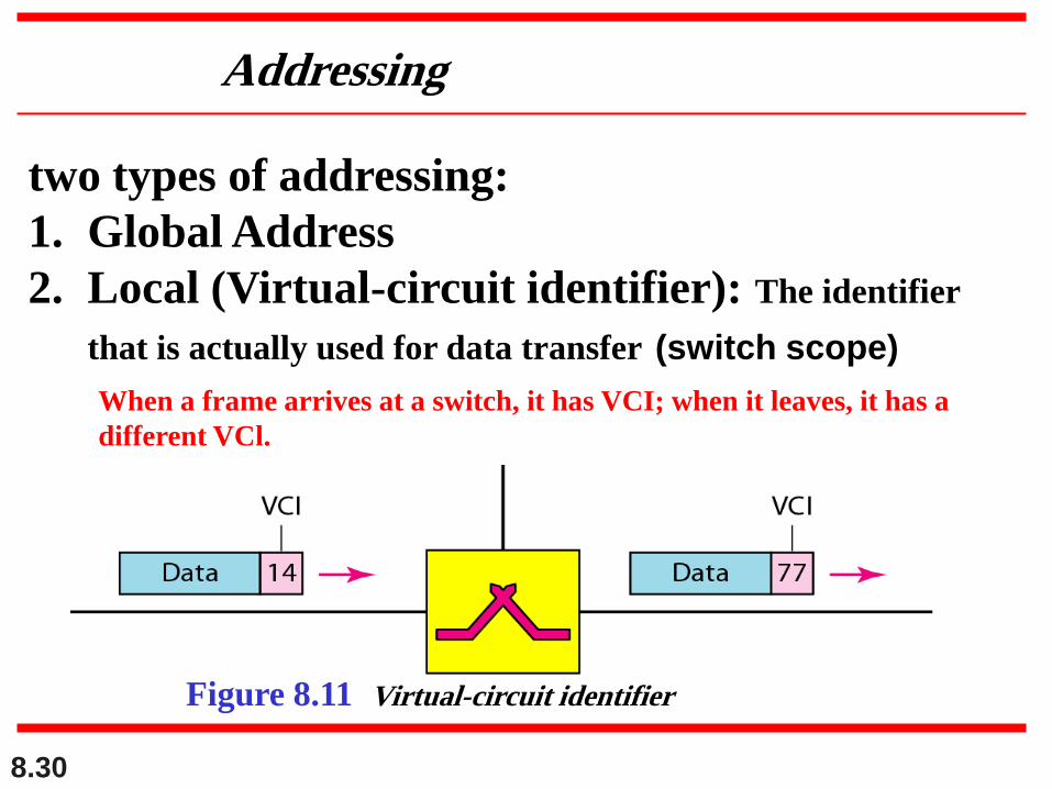
Figure 8.11 Virtual-circuit identifier
Addressing
two types of addressing:
1. Global Address
2. Local (Virtual-circuit identifier): The identifier
that is actually used for data transfer (switch scope)
When a frame arrives at a switch, it has VCI; when it leaves, it has a
different VCl.
8.31
3 phases
setup, data transfer, and teardown.1. Setup: the source and destination use their global addresses
to help switches make table entries for the connection.
2. the source and destination inform the switches to delete the
corresponding entry.
3. occurs between these two phases.
8.32
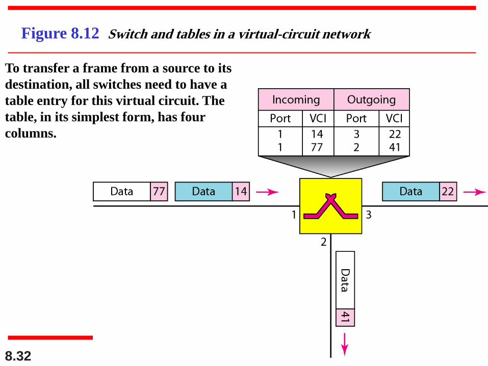
Figure 8.12 Switch and tables in a virtual-circuit network
To transfer a frame from a source to its
destination, all switches need to have a
table entry for this virtual circuit. The
table, in its simplest form, has four
columns.
8.33
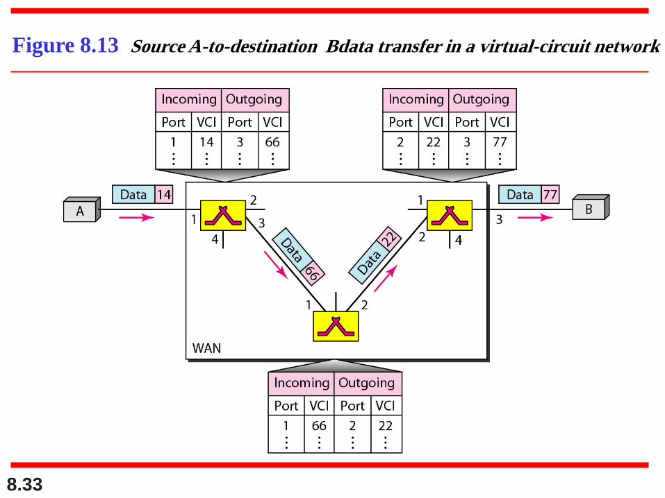
Figure 8.13 Source A-to-destination Bdata transfer in a virtual-circuit network
8.34
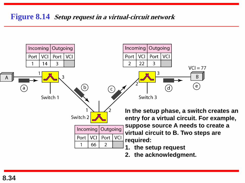
Figure 8.14 Setup request in a virtual-circuit network
In the setup phase, a switch creates an
entry for a virtual circuit. For example,
suppose source A needs to create a
virtual circuit to B. Two steps are
required:
1. the setup request
2. the acknowledgment.
8.35
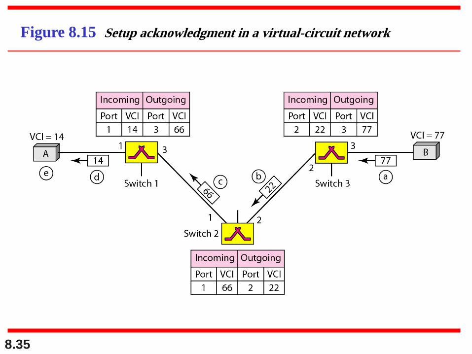
Figure 8.15 Setup acknowledgment in a virtual-circuit network
8.36
Teardowil Phase: In this phase, source A, after
sending all frames to B, sends a special frame
called a teardown request.
Teardown Phase
8.37
In virtual-circuit switching, all packets
belonging to the same source and
destination travel the same path;
but the packets may arrive at the
destination with different delays
if resource allocation is on demand.
Note
Efficiency
8.38
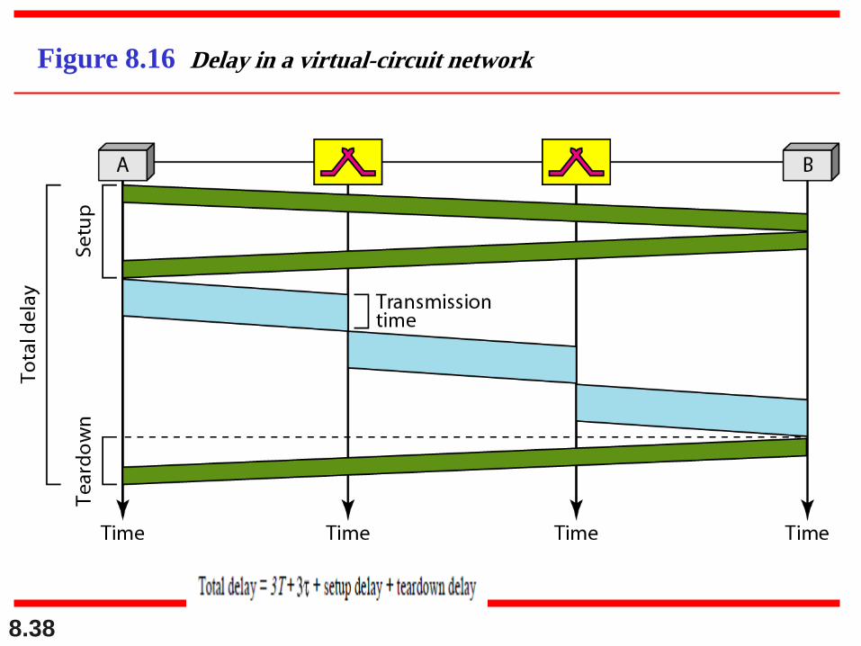
Figure 8.16 Delay in a virtual-circuit network
8.39
Switching at the data link layer in a
switched WAN is normally implemented
by using virtual-circuit techniques.
Note
8.40
8-4 STRUCTURE OF A SWITCH
We use switches in circuit-switched and packet-
switched networks. In this section, we discuss the
structures of the switches used in each type of
network.
Structure of Circuit Switches
Structure of Packet Switches
Topics discussed in this section:
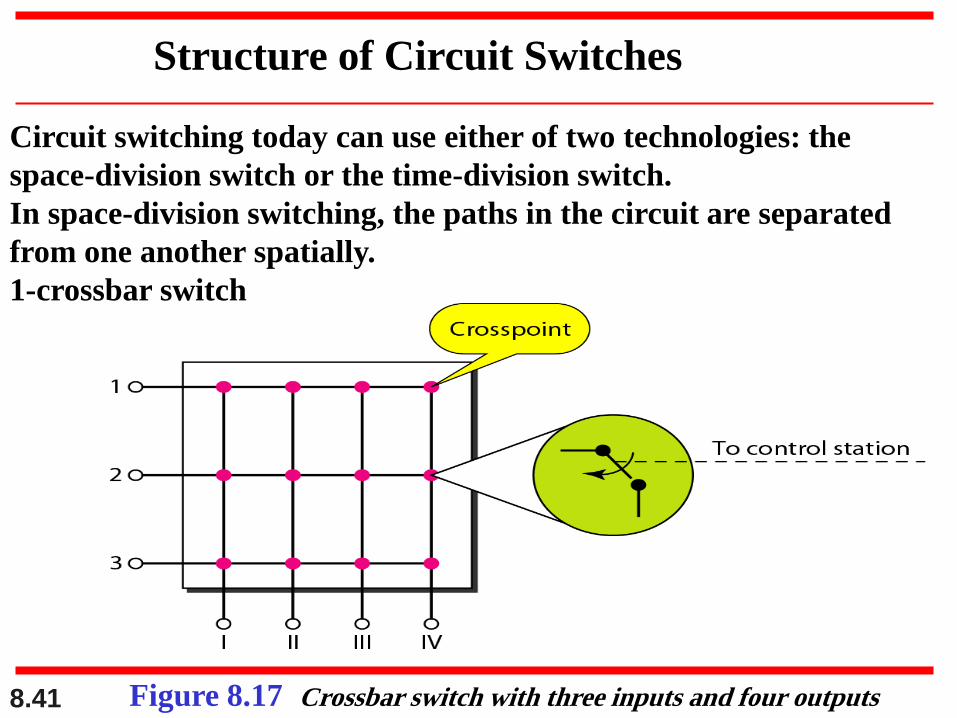
8.41 Figure 8.17 Crossbar switch with three inputs and four outputs
Structure of Circuit Switches
Circuit switching today can use either of two technologies: the
space-division switch or the time-division switch.
In space-division switching, the paths in the circuit are separated
from one another spatially.
1-crossbar switch
8.42
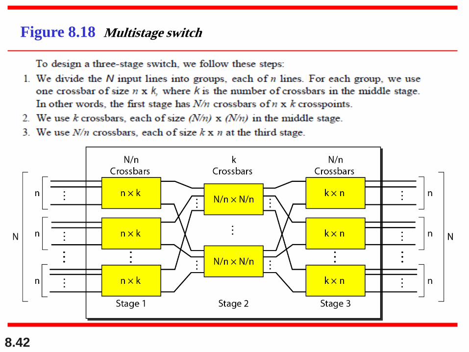
Figure 8.18 Multistage switch
8.43
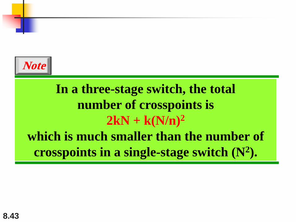
In a three-stage switch, the total
number of crosspoints is
2kN + k(N/n)2
which is much smaller than the number of
crosspoints in a single-stage switch (N2).
Note

8.44
Design a three-stage, 200 × 200 switch (N = 200) with
k = 4 and n = 20.
Solution
In the first stage we have N/n or 10 crossbars,each of size 20 × 4. In the second stage, we have4 crossbars, each of size 10 × 10. In the thirdstage, we have 10 crossbars, each of size 4 × 20.The total number of crosspoints is 2kN + k(N/n)2,or 2000 crosspoints. This is 5 percent of thenumber of crosspoints in a single-stage switch(200 × 200 = 40,000).
Example 8.3
8.45
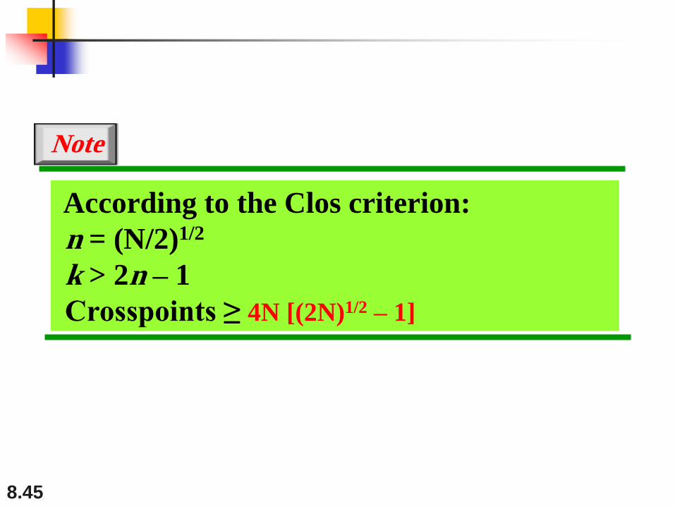
According to the Clos criterion:
n = (N/2)1/2
k > 2n – 1
Crosspoints ≥ 4N [(2N)1/2 – 1]
Note
8.46
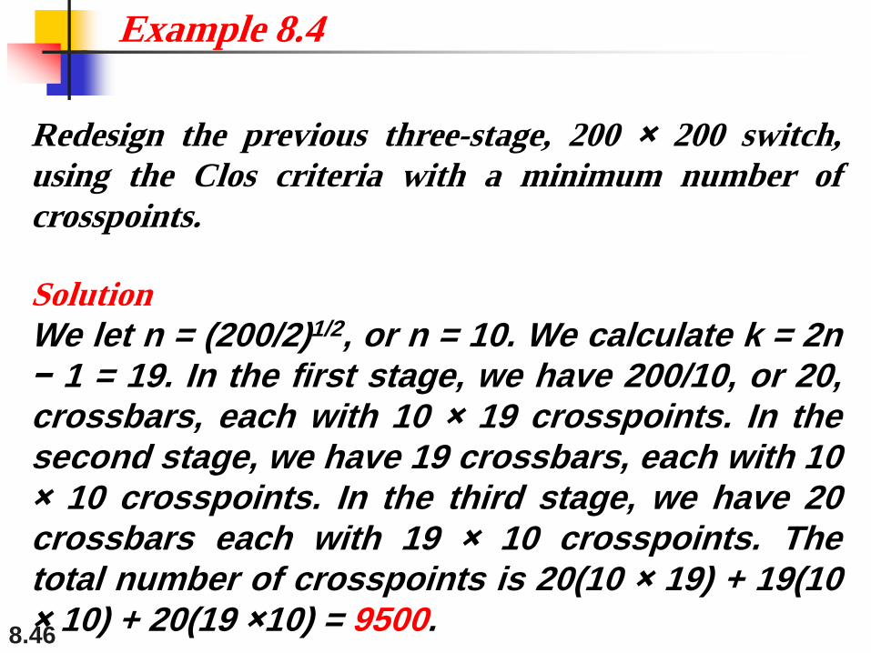
Redesign the previous three-stage, 200 × 200 switch,
using the Clos criteria with a minimum number of
crosspoints.
Solution
We let n = (200/2)1/2, or n = 10. We calculate k = 2n− 1 = 19. In the first stage, we have 200/10, or 20,crossbars, each with 10 × 19 crosspoints. In thesecond stage, we have 19 crossbars, each with 10× 10 crosspoints. In the third stage, we have 20crossbars each with 19 × 10 crosspoints. Thetotal number of crosspoints is 20(10 × 19) + 19(10× 10) + 20(19 ×10) = 9500.
Example 8.4
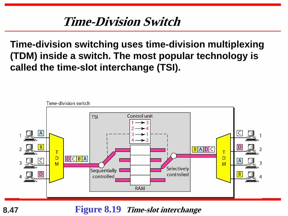
8.47 Figure 8.19 Time-slot interchange
Time-Division Switch
Time-division switching uses time-division multiplexing
(TDM) inside a switch. The most popular technology is
called the time-slot interchange (TSI).
8.48
Time-space-time switch
space-division adv. The advantage of space-division switching is that it
is instantaneous
Dis. the number of cross-points required
Time –division
Adv. No need of cross-points.
Dis. is that processing each connection creates delays.
Each time slot must be stored by the RAM, then
retrieved and passed on.
8.49
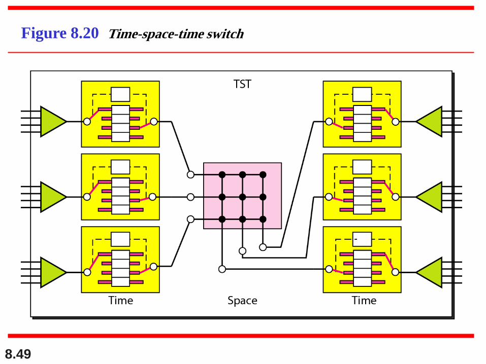
Figure 8.20 Time-space-time switch
8.50
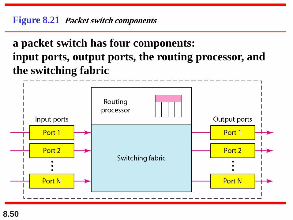
Figure 8.21 Packet switch components
a packet switch has four components:
input ports, output ports, the routing processor, and
the switching fabric

8.51
Figure 8.22 Input port
An input port performs the physical and data link functions of
the packet switch. The bits are constructed from the received
signal. The packet is de-capsulated from the frame. Errors are
detected and corrected. The packet is now ready to be routed by
the network
8.52
ROllting Processor
The routing processor performs the functions of the network layer.
The destination address is used to find the address of the next hop
and, at the same time, the output port number from which the
packet is sent out.
Switching "Fabrics
The most difficult task in a packet switch is to move the packet
from the input queue to the output queue. The speed with which
this is done affects the size of the input/output queue and the
overall delay in packet delivery. As crossbar switch and banyan
switch
8.53
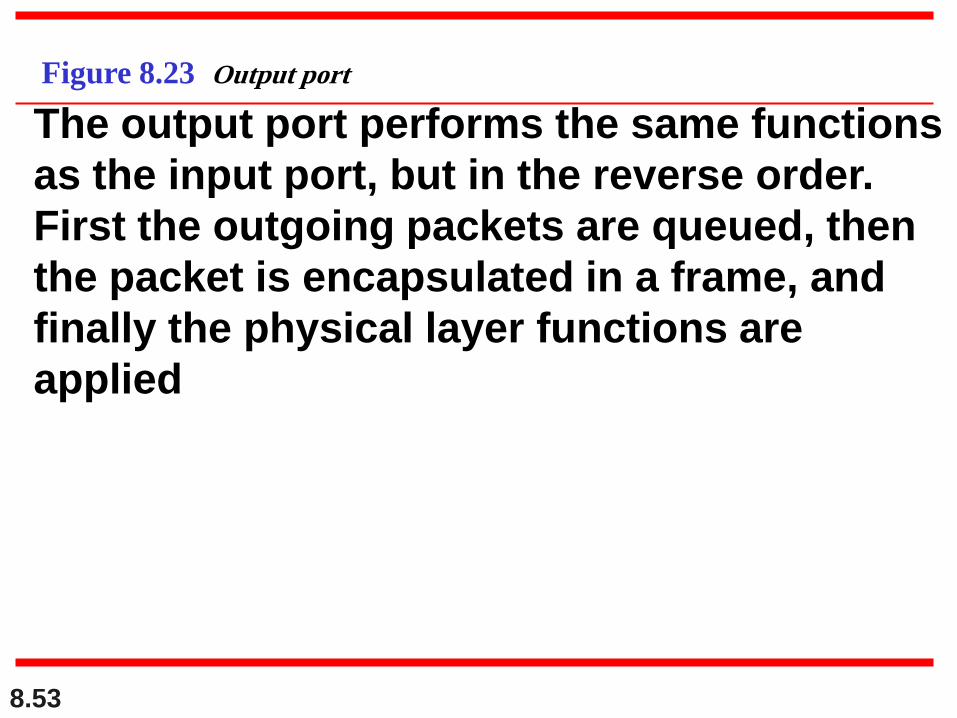
Figure 8.23 Output port
The output port performs the same functions
as the input port, but in the reverse order.
First the outgoing packets are queued, then
the packet is encapsulated in a frame, and
finally the physical layer functions are
applied
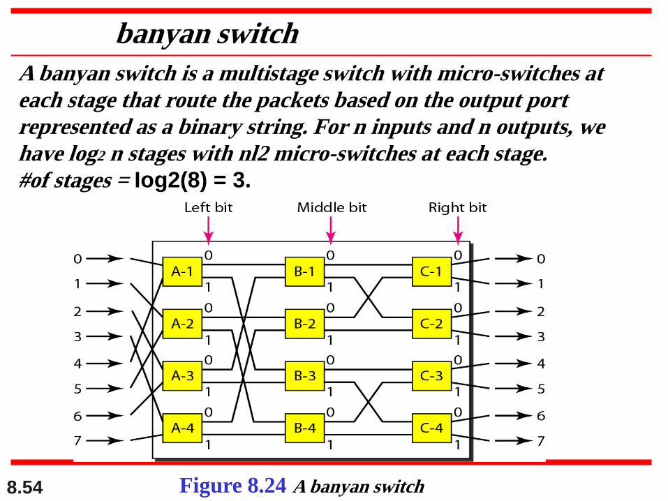
8.54 Figure 8.24 A banyan switch
banyan switch
A banyan switch is a multistage switch with micro-switches at
each stage that route the packets based on the output port
represented as a binary string. For n inputs and n outputs, we
have log2 n stages with nl2 micro-switches at each stage.
#of stages = Iog2(8) = 3.
8.55
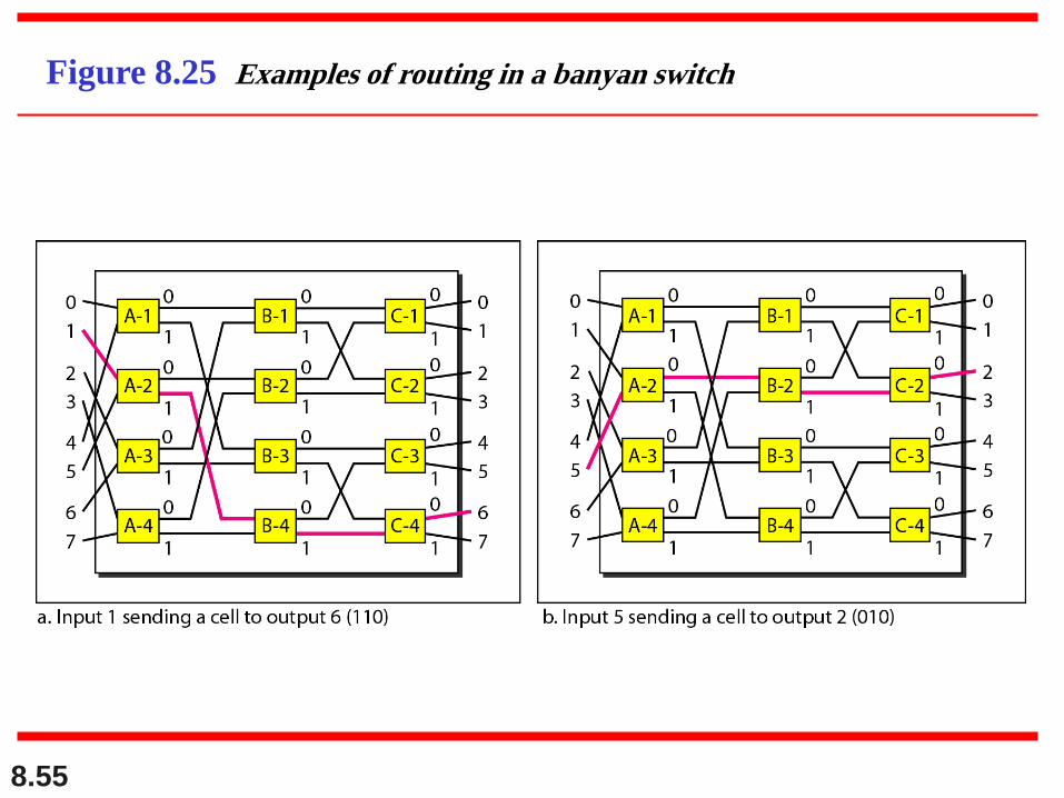
Figure 8.25 Examples of routing in a banyan switch
8.56
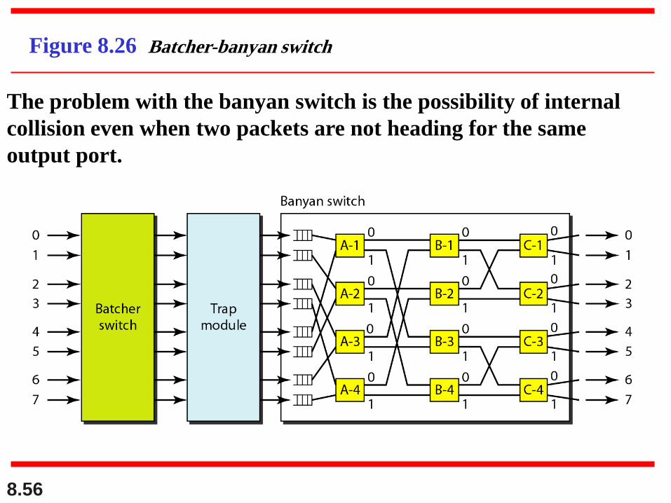
Figure 8.26 Batcher-banyan switch
The problem with the banyan switch is the possibility of internal
collision even when two packets are not heading for the same
output port.


![INGENIER¶IADETRAFICO¶ ENL¶INEAENREDESMPLS … · La Arquitectura MPLS (MultiProtocol Label Swiching)[39] es una nueva arquitectura que habilita a realizar Ingenier¶‡a de Tr¶aflco](https://img.pdfslide.net/doc/110x75/5e770320bd2f62157f2d8448/ingenieriadetrafico-enlineaenredesmpls-la-arquitectura-mpls-multiprotocol.jpg)