Embed Size (px)
Citation preview

SOFTWARE ENGINEERING
Subject Code: 10IS51 I.A. Marks : 25 Hours/Week : 04 Exam Hours: 03 Total Hours : 52 Exam Marks: 100
PART – A
UNIT – 1 6 Hours Overview: Introduction: FAQ's about software engineering, Professional and ethical responsibility. Socio-Technical systems: Emergent system properties; Systems engineering; Organizations, people and computer systems; Legacy systems. UNIT – 2 6 Hours Critical Systems, Software Processes: Critical Systems: A simple safety-critical system; System dependability; Availability and reliability. Software Processes: Models, Process iteration, Process activities; The Rational Unified Process; Computer Aided Software Engineering. UNIT – 3 7 Hours Requirements: Software Requirements: Functional and Non-functional requirements; User requirements; System requirements; Interface specification; The software requirements document. Requirements Engineering Processes: Feasibility studies; Requirements elicitation and analysis; Requirements validation; Requirements management. UNIT – 4 7 Hours System models, Project Management: System Models: Context models; Behavioral models; Data models; Object models; Structured methods. Project Management: Management activities; Project planning; Project scheduling; Risk management.
PART - B
UNIT – 5 7 Hours Software Design : Architectural Design: Architectural design decisions; System organization; Modular decomposition styles; Control styles. Object-Oriented design: Objects and Object Classes; An Object-Oriented design process; Design evolution. UNIT – 6 6 Hours Development: Rapid Software Development: Agile methods; Extreme programming; Rapid application development. Software Evolution: Program evolution dynamics; Software maintenance; Evolution processes; Legacy system evolution. UNIT – 7 7 Hours Verification and Validation: Verification and Validation: Planning; Software inspections; Automated static analysis; Verification and formal methods. Software testing: System testing; Component testing; Test case design; Test automation. UNIT – 8 6 Hours Management: Managing People: Selecting staff; Motivating people; Managing people; The People Capability Maturity Model. Software Cost Estimation: Productivity; Estimation techniques; Algorithmic cost modeling, Project duration and staffing. Text Books:
1. Ian Sommerville: Software Engineering, 8th Edition, Pearson Education, 2007. (Chapters-: 1, 2, 3, 4, 5, 6, 7, 8, 11, 14, 17, 21, 22, 23, 25, 26)
Reference Books:
1. Roger.S.Pressman: Software Engineering-A Practitioners approach, 7th Edition, McGraw Hill, 2007. 2. Pankaj Jalote: An Integrated Approach to Software Engineering, 3rd Edition, Narosa Publishing House,
2005.
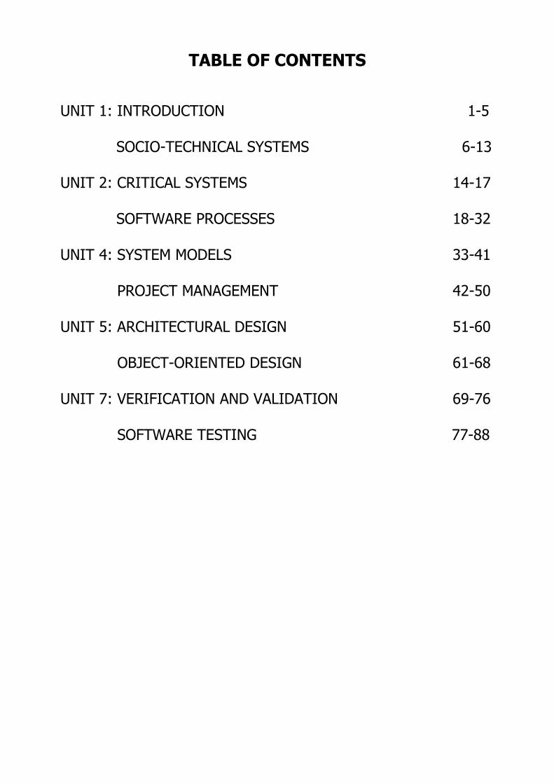
TABLE OF CONTENTS
UNIT 1: INTRODUCTION 1-5 SOCIO-TECHNICAL SYSTEMS 6-13 UNIT 2: CRITICAL SYSTEMS 14-17 SOFTWARE PROCESSES 18-32 UNIT 4: SYSTEM MODELS 33-41
PROJECT MANAGEMENT 42-50 UNIT 5: ARCHITECTURAL DESIGN 51-60
OBJECT-ORIENTED DESIGN 61-68 UNIT 7: VERIFICATION AND VALIDATION 69-76
SOFTWARE TESTING 77-88
SOFTWARE ENGINEERING
Success could be described as 50/50 - 50% vision and 50% action.
1
UNIT 1: INTRODUCTION
What is Software?
• Software is a set of computer-programs and associated documentation.
• A software-system consists of a no. of programs such as
→ configuration-files used to set-up programs
→ system-documentation describes the structure of the system and
→ user-documentation explains how to use the system.
• Two types of software-products:
1) Generic Developed to be sold to a range of different customers.
2) Bespoke (custom)
Developed for a single customer according to their specification.
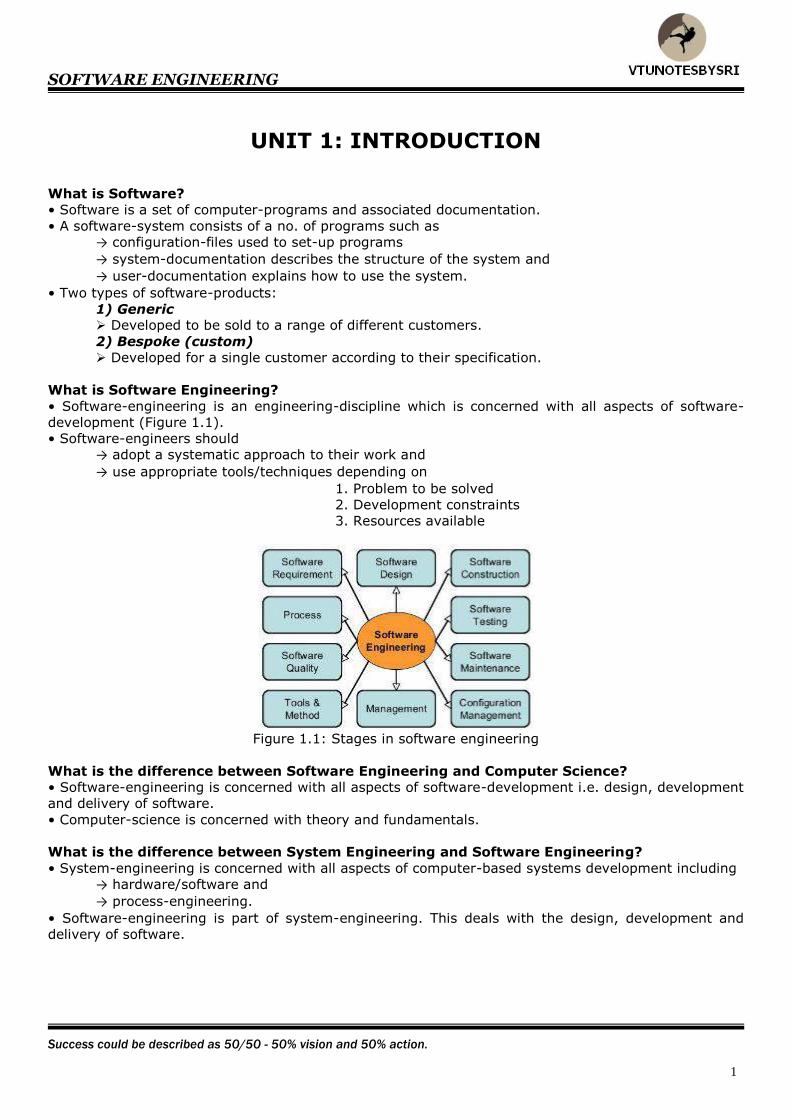
What is Software Engineering?
• Software-engineering is an engineering-discipline which is concerned with all aspects of software-
development (Figure 1.1).
• Software-engineers should
→ adopt a systematic approach to their work and
→ use appropriate tools/techniques depending on
1. Problem to be solved
2. Development constraints
3. Resources available
Figure 1.1: Stages in software engineering
What is the difference between Software Engineering and Computer Science?
• Software-engineering is concerned with all aspects of software-development i.e. design, development
and delivery of software.
• Computer-science is concerned with theory and fundamentals.
What is the difference between System Engineering and Software Engineering?
• System-engineering is concerned with all aspects of computer-based systems development including
→ hardware/software and
→ process-engineering.
• Software-engineering is part of system-engineering. This deals with the design, development and
delivery of software.

SOFTWARE ENGINEERING
Knowing is not enough; we must apply. Willing is not enough; we must do.
2
What is a Software Process?
• A set of activities whose goal is the development of software.
• Four main activities:
1. Software Specification This answers following questions:
→ what does the customer need?
→ what are the constraints?
2. Software Development Software is designed and programmed.
3. Software Validation
Software is checked to ensure that it is what the customer requires.
4. Software Evolution Software is modified to adapt to changing customer- and market-requirements.
What is a Software Process Model?
• A simplified representation of a software-process, presented from a specific perspective.
• Process-models may include
→ activities part of the software-process and
→ roles of people involved.
• Examples of process-model:
1. A Workflow Model
This shows
→ sequence of activities in the process and
→ inputs & outputs of activities.
The activities represent human-actions.
2. A Dataflow( or Activity model) This represents the process as a set of activities.
Each activity carries out some data-transformation.
The activities may be carried out by
→ people or
→ computers.
3. A Role/Action Model
This represents
→ roles of the people involved in the process and
→ activities for which the people are responsible.
Generic Models
1. The Waterfall Approach
• This represents the activities as separate process-phases such as
→ design
→ implementation and
→ testing.
• After each stage is defined, it is 'signed-off, and development goes on to the next stage.
2. Iterative Development
• This approach interleaves the activities of
→ specification
→ development and
→ validation.
• An initial-system is rapidly developed from very abstract-specifications.
• The initial-system is then refined with customer-input to produce a system that satisfies the
customer’s needs.
• The system may then be delivered.
3. CBSE (Component-based Software Engineering)
• This approach assumes that parts of the system already exist.
• The development-process focuses on integrating the available parts (rather than developing them
from scratch).
SOFTWARE ENGINEERING
First say to yourself what you would be, then do what you have to do.
3
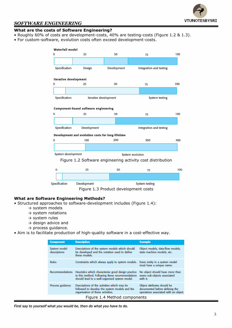
What are the costs of Software Engineering?
• Roughly 60% of costs are development-costs, 40% are testing-costs (Figure 1.2 & 1.3).
• For custom-software, evolution costs often exceed development-costs.
Figure 1.2 Software engineering activity cost distribution
Figure 1.3 Product development costs
What are Software Engineering Methods?
• Structured approaches to software-development includes (Figure 1.4):
→ system models
→ system notations
→ system rules
→ design advice and
→ process guidance.
• Aim is to facilitate production of high-quality software in a cost-effective way.
Figure 1.4 Method components
SOFTWARE ENGINEERING
There is always, always, always something to be thankful for.
4
What is CASE?
• CASE stands Computer-Aided Software Engineering.
• CASE is software-system designed to support routine-activities in software-process.
• Routine activities include
→ editing design diagrams
→ checking diagram consistency and
→ keeping track of program tests that have been run.
What are the attributes of good software?
1) Maintainability
• Software should be written in such a way that it may evolve to meet the changing needs of
customers.
2) Dependability
• Dependability has a range of features such as
→ reliability
→ security and
→ safety.
• Dependable-software should not cause physical or economic damage in event of failure.
3) Efficiency
• Software should not waste system-resources such as
→ memory-cycles and
→ processor-cycles.
• Efficiency includes
→ response-time
→ processing-time and
→ memory-utilization.
4) Usability
• Software must be usable, without undue effort, by the user.
• Software should have an appropriate
→ user interface and
→ proper documentation.
What are the key challenges facing Software Engineering?
1. The Heterogeneity Challenge
• Increasingly, systems are required to operate across networks that include
→ different types of computers
→ different kinds of support systems and
→ different platforms.
• It is often necessary to integrate new software with older legacy-systems.
2. The Delivery Challenge
• The challenge is shortening delivery-times for large systems without compromising system-quality.
• Many traditional software engineering techniques are time-consuming.
• However, businesses today change very rapidly. So, their supporting-software must change equally
rapidly.
3. The Trust Challenge
• The challenge is to demonstrate that the software can be trusted by its users.
• As software is a part of many aspects of our lives (work, study, leisure), it is essential that we can
trust that software.
• This is true for remote-systems accessed through a web-page interface.
SOFTWARE ENGINEERING
Do not go where the path may lead, go instead where there is no path and leave a trail.
5
Professional and Ethical Responsibility
1. Confidentiality
• You should normally respect the confidentiality of your employers or clients.
2. Competence
• You should not misrepresent your level of capability.
• You should not knowingly accept work that is outside your capability.
3. Intellectual Property Rights
• You should be aware of local laws governing the use of intellectual property such as
→ patents and
→ copyright.
• You should be careful to ensure that the intellectual property of employers and clients is protected.
4. Computer Misuse
• You should not use your technical skills to misuse other people's computers.
• Computer misuse ranges
→ from relatively trivial (game playing on an employer’s machine)
→ to extremely serious (distribution of viruses).
SOFTWARE ENGINEERING
This one step, choosing a goal and sticking to it, changes everything.
6
UNIT 1(CONT.): SOCIO-TECHNICAL SYSTEMS
Introduction
• A system is a purposeful collection of interrelated components that work together to achieve some
objective.
• Two categories of systems:
1) Technical Computer-based Systems
These are systems that include hardware- and software-components but not procedures and
processes. Examples: televisions, mobile phones.
2) Socio-technical Systems These include one or more technical systems.
These also include knowledge of how the system should be used to achieve some broader
objective. These systems have defined operational processes.
These systems include people (the operators) who are governed by organizational policies
and rules.
Essential characteristics of Socio-technical Systems
1. They have emergent properties that are properties of the system as a whole rather than associated
with individual parts of the system.
Emergent properties depend on both
→ system-components and
→ relationships between components
2. They are often non-deterministic. i.e. when presented with a specific input, they may not always
produce the same output.
3. The extent to which the system supports organisational-objectives depends on
→ stability of the objectives
→ relationships and conflicts between objectives and
→ how people in the organisation interpret the objectives.
Emergent System Properties
1. Functional Emergent Properties
• These appear when all the parts of a system work together to achieve some objective.
• For example, a bicycle has the functional property of being a transportation-device once it has been
assembled from its components.
2. Non-functional Emergent
• These properties relate to the behaviour of the system in its operational environment.
• Examples are
→ reliability
→ performance
→ safety and
→ securi1ty.
SOFTWARE ENGINEERING
Without goals and a plan to reach them, you are like a ship that has set sail with no destination.
7
Examples of Emergent Properties
Volume
• The volume of a system (the total space occupied) varies depending on how the component
assemblies are arranged and connected.
Reliability
• System-reliability depends on component-reliability.
• Unexpected interactions between components can cause new types of failure and therefore affect the
reliability of the system.
•There are 3 related influences on the overall reliability of a system:
1. Hardware Reliability
How long does it take to repair that component?
2. Software Reliability How likely is it that a software-component will produce an incorrect output?
3. Operator Reliability How likely is it that the operator of a system will make an error?
Security
• The security of the system is a complex property that cannot be easily measured.
• Attacks may be devised that were not anticipated by the system-designers and so may defeat built-in
safeguard.
Repairability
• This property reflects how easy it is to fix a problem with the system once it has been discovered.
• It depends on being able to
→ diagnose the problem
→ access the components that are faulty and
→ modify or replace the components.
Usability
• This property reflects how easy it is to use the system.
• It depends on
→ technical system-components
→ component’s operators and
→ component’s operating environment.

SOFTWARE ENGINEERING
The man who can drive himself farther once the effort gets painful, is the man who will win.
8
Systems Engineering
• This is the activity of specifying, designing, implementing, validating, deploying and maintaining
socio-technical systems (Figure 2.2).
• System-engineers are concerned with
→ software & hardware and
→ system's interactions with users and its environment.
Figure 2.2 The systems engineering process
• System engineering process vs. software development process
1. Limited scope for rework during System Development Once some system-engineering decisions have been made, they are very expensive to
change.
2. Interdisciplinary Involvement
Many engineering disciplines may be involved in system-engineering.
System Requirements Definitions
• These specify what the system should do (its functions) and its essential and desirable system
properties.
• Three types of requirements:
1. Abstract Functional Requirements
The basic functions that the system must provide are defined at an abstract-level.
More detailed requirements are defined at the subsystem-level.
2. System Properties
These are non-functional emergent system properties such as
→ availability
→ performance and
→ safety.
3. Characteristics that the System must not exhibit It is sometimes as important to specify what the system must not do as it is to specify what
the system should do.

SOFTWARE ENGINEERING
Within us are the seeds of triumph or defeat. Which seeds will you plant?
9
System Design
• This is concerned with how the system functionality is to be provided by the components of the
system (Figure 2.4).
Figure 2.4 The system design process
• Activities in design process:
1. Partition Requirements You analyse the requirements and organise them into related groups.
2. Identify Subsystems
You should identify subsystems that can individually or collectively meet the requirements.
Subsystem identification may also be influenced by other organizational or environmental
factors.
3. Assign Requirements to Subsystems This should be straightforward if the requirements partitioning is used to drive the subsystem
identification.
4. Specify Subsystem Functionality You should specify the specific functions provided by each subsystem.
You should also try to identify relationships between subsystems.
5. Define Subsystem Interfaces You define the interfaces that are provided and required by each subsystem.
Once these interfaces have been agreed upon, it is possible to develop these subsystems in
parallel.
SOFTWARE ENGINEERING
Failure is a success if we learn from it.
10
System Modelling
• The system is decomposed into a set of interacting subsystems.
• Each subsystem should be represented in a similar way until the system is decomposed into
functional components.
• Functional components provide a single function.
By contrast, a subsystem usually is multifunctional.
• These are normally illustrated graphically in a system-architecture model
• The system-architecture may be presented as a block diagram showing
→ major subsystems and
→ interconnections between these subsystems.
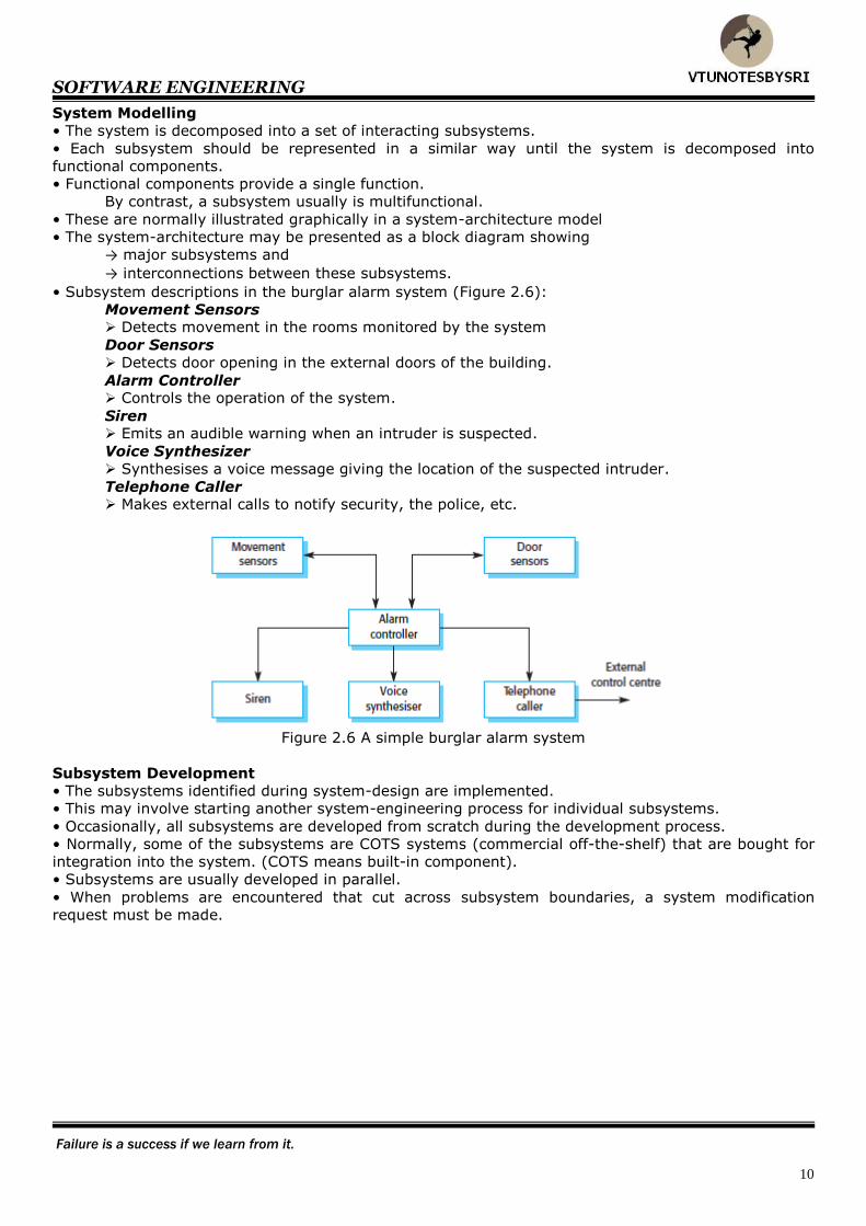
• Subsystem descriptions in the burglar alarm system (Figure 2.6):
Movement Sensors Detects movement in the rooms monitored by the system
Door Sensors
Detects door opening in the external doors of the building.
Alarm Controller Controls the operation of the system.
Siren Emits an audible warning when an intruder is suspected.
Voice Synthesizer
Synthesises a voice message giving the location of the suspected intruder.
Telephone Caller Makes external calls to notify security, the police, etc.
Figure 2.6 A simple burglar alarm system
Subsystem Development
• The subsystems identified during system-design are implemented.
• This may involve starting another system-engineering process for individual subsystems.
• Occasionally, all subsystems are developed from scratch during the development process.
• Normally, some of the subsystems are COTS systems (commercial off-the-shelf) that are bought for
integration into the system. (COTS means built-in component).
• Subsystems are usually developed in parallel.
• When problems are encountered that cut across subsystem boundaries, a system modification
request must be made.
SOFTWARE ENGINEERING
People with goals succeed because they know where they are going.
11
Systems Integration
• The basic idea:
1. Take the independently developed subsystems and
2. Then, integrate them to make up a complete system.
• In incremental-integration, subsystems are integrated one at a time.
• Incremental-integration is considered best approach for 2 reasons:
1. Usually, it is impossible to schedule the development of all the subsystems
so that all subsystems are all developed at the same time.
2. Incremental integration reduces the cost of error-location.
• Once the components are integrated, an extensive system-testing takes place.
• Faults that are a consequence of invalid assumptions about other subsystems are often exposed.
System Evolution
• Large, complex systems have a very long lifetime. They must evolve to meet changing requirements.
• Four reasons why evolution is costly:
1. Changes must be analysed from a technical- and business-perspective.
2. When subsystems interact, unanticipated problems can arise.
3. There is rarely a justification for original design decisions.
4. System-structure is corrupted, as changes are made to it.
• Systems that have evolved over time are often dependent on obsolete hardware/software
technology. If they have a critical role in an organisation, they are known as legacy systems.
System Decommissioning
• This means taking the system out-of-service after the end of its useful operational lifetime.
• For hardware systems, this may involve disassembling and recycling materials or dealing with toxic
substances.
• Software has no physical decommissioning problems,
but some software may be incorporated in a system to assist with decommissioning process.
• If the data in the decommissioned-system is still valuable to your organisation,
then you may have to convert it for use by some other system.

SOFTWARE ENGINEERING
Excellence is not being the best; it is doing your best.
12
Organisations, People and Computer Systems
• Following human and organisational factors affect the system-design:
1. Process Changes Does the system require changes to the work processes in the environment?
If so, training will certainly be required.
2. Job Changes Does the system de-skill the users in an environment or cause them to change the way they
work? If so, they may actively resist the introduction of the system into the organisation.
3. Organisational Changes Does the system change the political power structure in an organisation?
Organisational Processes
• The procurement process is normally embedded within client-organization (Figure 2.9).
• The system-procurement is concerned with
→ making decisions about the best way for an organisation to acquire a system and
→ deciding on the best suppliers of the system.
• Large complex systems usually consist of a mixture of
→ off-the-shelf and
→ specially built-in components.
• Why more and more software is included in systems?
Ans: This allows more use of existing hardware-components, with the software acting as a 'glue' to
make these hardware components work together effectively.
Figure 2.9 Procurement, development and operational processes
• Some important points about the process shown in Figure 2.10 are:
1. Off-the-shelf components do not usually match requirements exactly.
2. When a system is to be built specially, the requirements-specification acts as the basis of a
contract for the system-procurement.
3. After a contractor has been selected, there is a contract-negotiation period where you may
have to
→ negotiate further changes to the requirements and
→ discuss issues such as the cost of changes to the system.
Figure 2.10 The system procurement process

SOFTWARE ENGINEERING
Don't limit your challenges; challenge your limits.
13
Legacy Systems
• These systems are socio-technical systems that have been developed in the past, often using older
technology.
• These systems include
→ hardware & software and
→ legacy processes & procedure.
• These systems are often business-critical systems. They are maintained because it is too risky to
replace them.
Figure 2.11 Legacy system components
• Logical parts of legacy system (Figure 2.11):
1. System Hardware In many cases, legacy-systems have been written for mainframe-hardware that is no longer
available.
The mainframe-hardware is expensive to maintain.
The mainframe-hardware may not be compatible with current organisational-policies.
2. Support Software
The legacy-system relies on OS & compilers provided by the old hardware-manufacturer.
Again, these softwares may be no longer supported by their original providers.
3. Application Software
The application-system is usually composed of a number of separate programs that have
been developed at different times.
4. Application Data
These are the data that are processed by the application-system.
In many legacy systems, an immense volume of data has accumulated over the lifetime of
the system.
5. Business Processes These processes are used in the business to achieve some business-objective.
Business-processes may be
→ designed around a legacy-system and
→ constrained by the functionality that it provides.
6. Business policies and Rules These are definitions of how the business should be carried out and constraints on the
business.

SOFTWARE ENGINEERING
Each day we must strive for constant and never ending improvement.
14
UNIT 2: CRITICAL SYSTEMS
Critical Systems
• These are socio-technical systems that people or businesses depend on.
• Failure of the systems results in → serious problems and
→ significant losses.
• Three main types:
1. Safety-critical Systems A system whose failure may result in
→ injury
→ loss of life or
→ serious environmental damage.
Example: control-system in a chemical manufacturing plant.
2. Mission-critical Systems
A system whose failure may result in the failure of some goal-directed activity.
Example: navigational-system in a spacecraft.
3. Business-critical Systems
A system whose failure may result in very high costs for the business.
Example: customer accounting-system in a bank.
• Dependability is the most important property of a critical-system.
• Why dependability is the most important property:
1. Systems that are unreliable, unsafe or insecure are often rejected by their users.
2. System-failure costs may be enormous.
3. Untrustworthy-systems may cause information-loss.
• Trusted methods (& techniques) must be used for development of critical-systems.
• Three components where failures may occur are:
l. System hardware may fail because
→ of mistakes in its design
→ components fail as a result of manufacturing-errors or
→ components have reached the end of their natural life.
2. System software may fail because → of mistakes in specification ,design or implementation.
3. Human operators of the system may fail to operate the system correctly.

SOFTWARE ENGINEERING
If you have a burning desire and a plan to take action, there is absolutely nothing you cannot achieve.
15
A Simple Safety-critical System
• There are 2 high-level dependability requirements for insulin pump system (Figure 3.1):
1. The system shall be available to deliver insulin when required (Figure 3.2).
2. The system shall perform reliably and deliver the correct amount of insulin.
Figure 3.1 Insulin pump structure
Figure 3.2 Data-flow model of the insulin pump
SOFTWARE ENGINEERING
Cause change and lead; accept change and survive; resist change and die.
16
System Dependability
• The dependability means the degree of user-confidence that
→ system will operate as they expect and
→ system will not 'fail' in normal use.
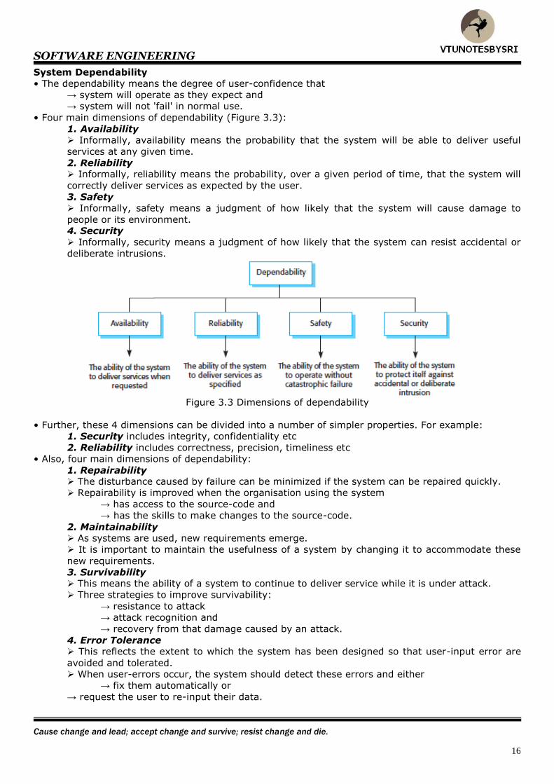
• Four main dimensions of dependability (Figure 3.3):
1. Availability Informally, availability means the probability that the system will be able to deliver useful
services at any given time.
2. Reliability Informally, reliability means the probability, over a given period of time, that the system will
correctly deliver services as expected by the user.
3. Safety Informally, safety means a judgment of how likely that the system will cause damage to
people or its environment.
4. Security
Informally, security means a judgment of how likely that the system can resist accidental or
deliberate intrusions.
Figure 3.3 Dimensions of dependability
• Further, these 4 dimensions can be divided into a number of simpler properties. For example:
1. Security includes integrity, confidentiality etc
2. Reliability includes correctness, precision, timeliness etc
• Also, four main dimensions of dependability:
1. Repairability The disturbance caused by failure can be minimized if the system can be repaired quickly.
Repairability is improved when the organisation using the system
→ has access to the source-code and
→ has the skills to make changes to the source-code.
2. Maintainability As systems are used, new requirements emerge.
It is important to maintain the usefulness of a system by changing it to accommodate these
new requirements.
3. Survivability This means the ability of a system to continue to deliver service while it is under attack.
Three strategies to improve survivability:
→ resistance to attack
→ attack recognition and
→ recovery from that damage caused by an attack.
4. Error Tolerance This reflects the extent to which the system has been designed so that user-input error are
avoided and tolerated. When user-errors occur, the system should detect these errors and either
→ fix them automatically or
→ request the user to re-input their data.
SOFTWARE ENGINEERING
The achievement of one goal should be the starting point of another.
17
Availability & Reliability
• The reliability means the probability, over a given period of time, that the system will correctly
deliver services as expected by the user.
• The availability means the probability that the system will be → up & running and
→ able to deliver useful services at any given time.
• Reliability and availability are compromised by system-failures. These may be → a failure to provide a service
→ a failure to deliver a service as specified or
→ insecure-delivery of a service.
• Differences between the terms fault, error and failure:
1) System Failure An event that occurs at some point in time when the system does not deliver a service as
expected by its users
2) System Error An erroneous-state that can lead to system-behaviour that is unexpected by users.
3) System Fault
A characteristic of a system that can lead to a error.
For example, failure to initialise a variable could lead to that variable having the wrong value
when it is used.
4) Human Error or Mistake Human-behaviour that results in the introduction of faults into a system.
• Three approaches to improve reliability of system:
1) Fault Avoidance Development techniques are used that either
→ minimise the possibility of mistakes or
→ trap mistakes before they result in the introduction of faults.
Examples include
→ avoiding error-prone programming language constructs such as pointers.
2) Fault Detection and Removal The use of V&V techniques that increase the chances that faults will be detected and removed
before the system is used. Examples include
→ testing and debugging.
3) Fault Tolerance Techniques that ensure that
→ faults in a system do not result in errors or
→ errors do not result in failures.
Examples include
→ incorporation of self-checking facilities in a system and
→ use of redundant system-modules.
SOFTWARE ENGINEERING
Concentrated thoughts produce desired results.
18
UNIT 2(CONT.): SOFTWARE PROCESSES
Software Process
• This is a set of activities carried out in developing software.
• Four main activities of software-process:
1. Software Specification The functionality of software and constraints on its operation must be defined.
2. Software Design and Implementation The software to meet the specification must be produced.
3. Software Validation
The software must be validated to ensure that it does what the customer wants.
4. Software Evolution The software must evolve to meet changing customer needs.
Software Process Model
• This is an abstract representation of a process.
• This provides guideline to organize how activities should be performed and in what order.
• Four process-models:
1. Waterfall model
2. Evolutionary Development
3. Component-based Software Engineering (CBSE)
4. Iterative Models
SOFTWARE ENGINEERING
Take a moment to reflect and recharge; its time well spent.
19
Waterfall Model
• This was the oldest software development approach.
• This is most commonly used model in software engineering.
• This is also called as linear sequential model.
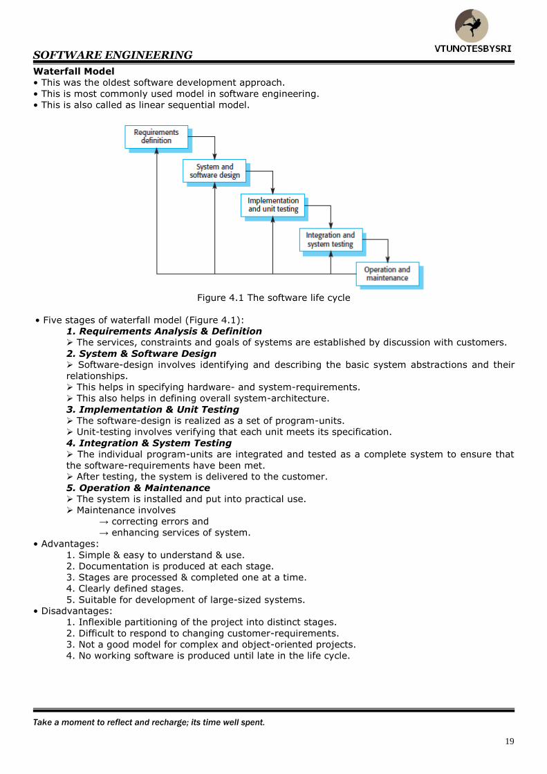
Figure 4.1 The software life cycle
• Five stages of waterfall model (Figure 4.1):
1. Requirements Analysis & Definition The services, constraints and goals of systems are established by discussion with customers.
2. System & Software Design Software-design involves identifying and describing the basic system abstractions and their
relationships.
This helps in specifying hardware- and system-requirements.
This also helps in defining overall system-architecture.
3. Implementation & Unit Testing
The software-design is realized as a set of program-units.
Unit-testing involves verifying that each unit meets its specification.
4. Integration & System Testing
The individual program-units are integrated and tested as a complete system to ensure that
the software-requirements have been met. After testing, the system is delivered to the customer.
5. Operation & Maintenance The system is installed and put into practical use.
Maintenance involves
→ correcting errors and
→ enhancing services of system.
• Advantages:
1. Simple & easy to understand & use.
2. Documentation is produced at each stage.
3. Stages are processed & completed one at a time.
4. Clearly defined stages.
5. Suitable for development of large-sized systems.
• Disadvantages:
1. Inflexible partitioning of the project into distinct stages.
2. Difficult to respond to changing customer-requirements.
3. Not a good model for complex and object-oriented projects.
4. No working software is produced until late in the life cycle.

SOFTWARE ENGINEERING
Success is the prize for those who stand true to their ideas.
20
Evolutionary Development
• This is also called as iterative model (Figure 4.2).
• The basic idea is:
1. Developers produce an initial version of the system rapidly.
2. Customers use the system and give feedback.
3. Developers modify the system based on feedback.
4. Repeat steps 2 and 3 until customers are satisfied.
Figure 4.2 Evolutionary development
• Two types are:
1. Exploratory Development The objective is to work with the customer to
→ explore the customer’s requirements and
→ deliver a final system.
The development starts with the parts of the system that are understood.
The system evolves by adding new features proposed by the customer.
2. Throwaway Prototyping The objective is to understand the customer-requirements and hence develop a better
requirements-definition for the system.
The prototype concentrates on experimenting with the customer-requirements that are poorly
understood.
• Advantages:
1. Specification can be developed incrementally.
2. Suitable for development of small and medium-sized systems.
3. Some working functionality can be developed quickly and early in the life cycle.
4. Parallel development can be planned.
5. It supports changing customer-requirements.
6. Users get a feel for the actual system in early stage.
• Disadvantages:
1. The process is not visible Managers need regular deliverables to measure progress (no documents other than the
system).
2. Systems are often poorly structured
Continual change tends to corrupt the software-structure.
Incorporating software changes becomes increasingly difficult and costly.
Not suitable for development of large, complex, long-lifetime systems.
SOFTWARE ENGINEERING
The day you stop giving is the day you stop receiving. The day you stop learning is the day you stop growing.
21
Component based Software Engineering (CBSE)
• The basic idea is
→ a library of reusable-components are available &
→ components are well documented so that they can be used correctly.
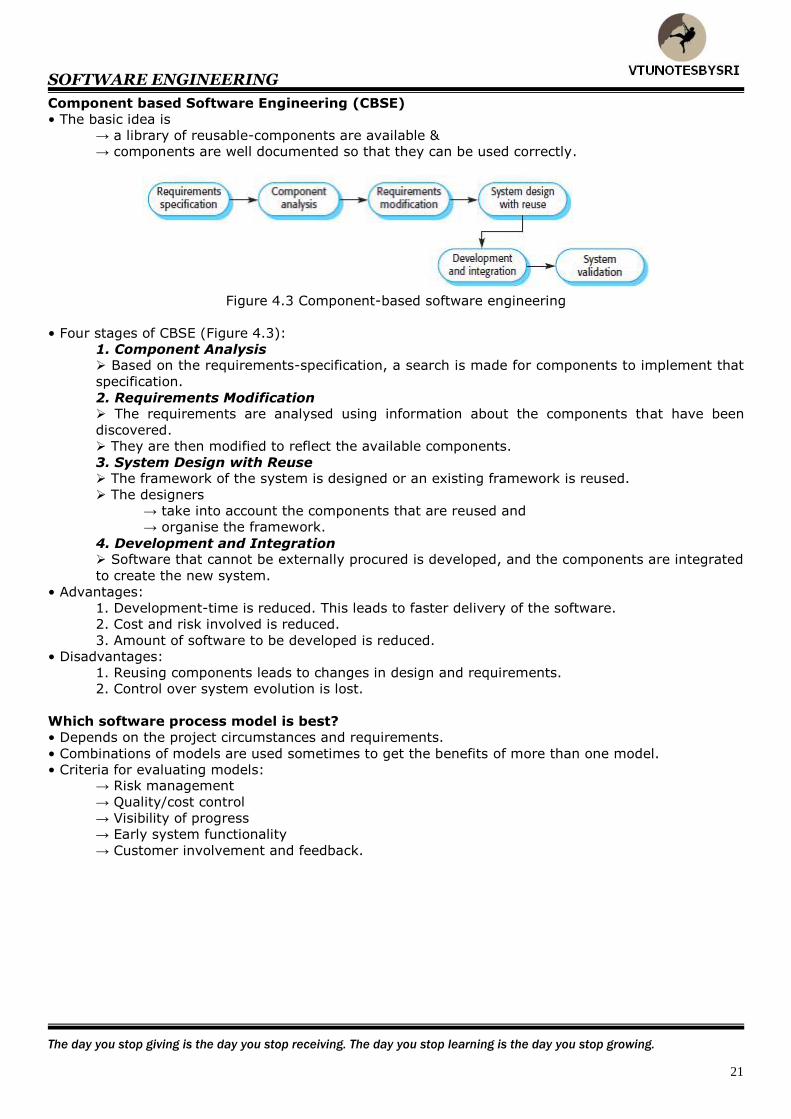
Figure 4.3 Component-based software engineering
• Four stages of CBSE (Figure 4.3):
1. Component Analysis Based on the requirements-specification, a search is made for components to implement that
specification.
2. Requirements Modification The requirements are analysed using information about the components that have been
discovered.
They are then modified to reflect the available components.
3. System Design with Reuse The framework of the system is designed or an existing framework is reused.
The designers
→ take into account the components that are reused and
→ organise the framework.
4. Development and Integration Software that cannot be externally procured is developed, and the components are integrated
to create the new system.
• Advantages:
1. Development-time is reduced. This leads to faster delivery of the software.
2. Cost and risk involved is reduced.
3. Amount of software to be developed is reduced.
• Disadvantages:
1. Reusing components leads to changes in design and requirements.
2. Control over system evolution is lost.
Which software process model is best?
• Depends on the project circumstances and requirements.
• Combinations of models are used sometimes to get the benefits of more than one model.
• Criteria for evaluating models: → Risk management
→ Quality/cost control
→ Visibility of progress
→ Early system functionality
→ Customer involvement and feedback.

SOFTWARE ENGINEERING
Success is the prize for those who stand true to their ideas.
22
Iterative Models
• Change is inevitable in all large projects.
• As management-priorities change, the system-requirements change.
• As new technologies become available, designs and implementation change.
• The process-activities are regularly repeated, as the system is reworked in response to change
requests.
• Two process models are:
1. Incremental Delivery The software specification, design and implementation are broken down into a series of
increments that are each developed in turn.
2. Spiral Development The development of the system spirals outwards from an initial outline through to the final
developed system.
Incremental Delivery
• This is an in-between approach that combines the advantages of waterfall and evolutionary models
(Figure 4.4).
Figure 4.4 Incremental delivery
• This delivers a series of releases called increments.
• The increments provide progressively more functionality for the customer, as each increment is
delivered.
• The first increment is often a core-product, where the basic requirements are addressed.
• The supplementary features are added in the next increments.
• Once the core-product is evaluated by the customer, there is plan-development for the next
increment. This process continues till the complete product is produced.
• Advantages:
1. Initial product delivery is faster i.e. customers do not have to wait until the entire system is
delivered.
2. Customer can respond to feature and review the product.
3. Lower risk of overall project-failure.
4. It is generally easier to test and debug.
• Disadvantages:
1. Increments should be relatively small (20,000 lines of code).
2. Each increment should deliver some system-functionality.
3. Resulting cost may exceed the cost of the organization.
4. Hard to identify common facilities needed by all increments.
5. Can be difficult to map the customer’s requirements onto increments of the right size.
SOFTWARE ENGINEERING
Your dreams minus your doubts equal your true worth.
23
Spiral Model
• This is a software development approach which is a combination of
→ an iterative nature of prototyping and
→ systematic aspects of waterfall model.
• Each loop represents a stage of the software-process.
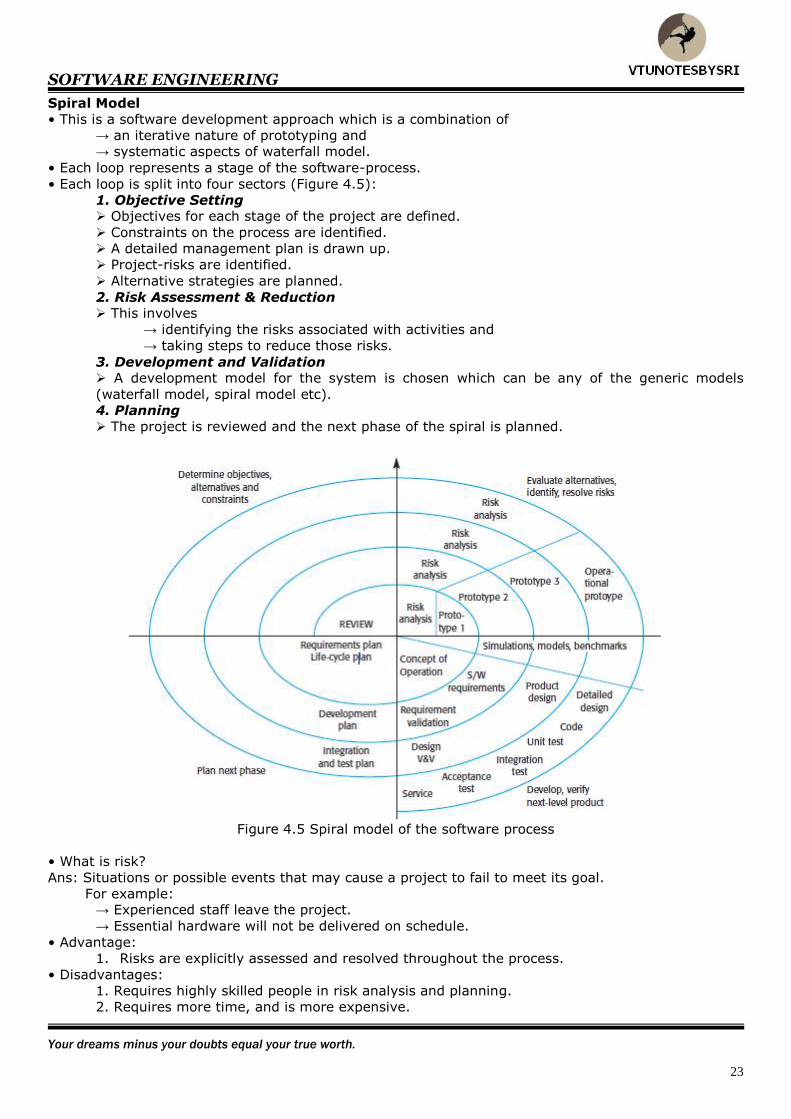
• Each loop is split into four sectors (Figure 4.5):
1. Objective Setting Objectives for each stage of the project are defined.
Constraints on the process are identified.
A detailed management plan is drawn up.
Project-risks are identified.
Alternative strategies are planned.
2. Risk Assessment & Reduction This involves
→ identifying the risks associated with activities and
→ taking steps to reduce those risks.
3. Development and Validation A development model for the system is chosen which can be any of the generic models
(waterfall model, spiral model etc).
4. Planning
The project is reviewed and the next phase of the spiral is planned.
Figure 4.5 Spiral model of the software process
• What is risk?
Ans: Situations or possible events that may cause a project to fail to meet its goal.
For example: → Experienced staff leave the project.
→ Essential hardware will not be delivered on schedule.
• Advantage:
1. Risks are explicitly assessed and resolved throughout the process.
• Disadvantages:
1. Requires highly skilled people in risk analysis and planning.
2. Requires more time, and is more expensive.
SOFTWARE ENGINEERING
Your success is only limited by your desire.
24
Process Activities • The four basic process-activities of specification, development, validation and evolution are organised
differently in different development processes.
• In waterfall model, the activities are organised in sequence.
Whereas, in evolutionary development, the activities are interleaved.
Software Specification
• This is also called requirements engineering.
• The basic idea:
1. Understand & define what services are required from the system and
2. Identify the constraints on the system's operation & development.
• Errors at this stage lead to later problems in the system-design and -implementation.
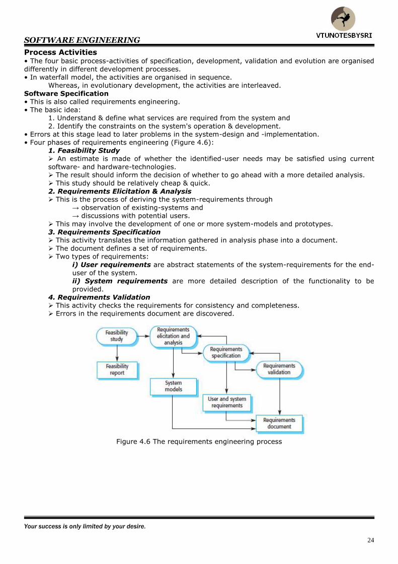
• Four phases of requirements engineering (Figure 4.6):
1. Feasibility Study
An estimate is made of whether the identified-user needs may be satisfied using current
software- and hardware-technologies. The result should inform the decision of whether to go ahead with a more detailed analysis.
This study should be relatively cheap & quick.
2. Requirements Elicitation & Analysis This is the process of deriving the system-requirements through
→ observation of existing-systems and
→ discussions with potential users.
This may involve the development of one or more system-models and prototypes.
3. Requirements Specification This activity translates the information gathered in analysis phase into a document.
The document defines a set of requirements.
Two types of requirements:
i) User requirements are abstract statements of the system-requirements for the end-
user of the system.
ii) System requirements are more detailed description of the functionality to be
provided.
4. Requirements Validation
This activity checks the requirements for consistency and completeness.
Errors in the requirements document are discovered.
Figure 4.6 The requirements engineering process
SOFTWARE ENGINEERING
Never stop learning. If you learn one new thing everyday, you will overcome 99% of your competition.
25
Software Design & Implementation
• The implementation-stage is the process of converting a system-specification into an executable-
system.
• A software-design is a description of → structure of the software
→ interfaces between the components and
→ algorithms used.
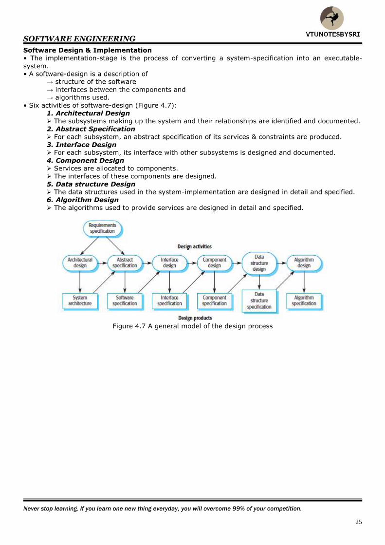
• Six activities of software-design (Figure 4.7):
1. Architectural Design The subsystems making up the system and their relationships are identified and documented.
2. Abstract Specification
For each subsystem, an abstract specification of its services & constraints are produced.
3. Interface Design For each subsystem, its interface with other subsystems is designed and documented.
4. Component Design Services are allocated to components.
The interfaces of these components are designed.
5. Data structure Design The data structures used in the system-implementation are designed in detail and specified.
6. Algorithm Design
The algorithms used to provide services are designed in detail and specified.
Figure 4.7 A general model of the design process

SOFTWARE ENGINEERING
It's a funny thing about life; if you refuse to accept anything but the best, you often get it.
26
Structured Method
• This includes
→ design process-model
→ notations to represent the design
→ report formats
→ rules and
→ design guidelines.
• Five supported models:
1. Object model This shows the object-classes used in the system and their dependencies.
2. Sequence model This shows how objects in the system interact when the system is executing.
3. State transition model
This shows system-states and the triggers for the transitions from one state to another.
4. Structural model The system-components and their aggregations are documented.
5. Data flow model The system is modelled using the data-transformations that take place as it is processed.
• Normally, programmers carry out some testing of the code.
• Testing often reveals defects which must be removed from the program. This is called debugging.
• Testing vs. Debugging. Testing establishes the existence of defects.
Debugging means locating and correcting these defects (Figure 4.8).
Figure 4.8 The debugging process
• Defects in the code must be located and the program modified to meet its requirements.
• Testing must then be repeated to ensure that the change has been made correctly.
SOFTWARE ENGINEERING
Never give up! Failure and rejection are only the first step to succeeding.
27
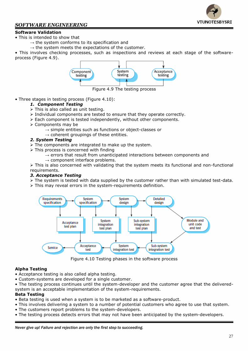
Software Validation
• This is intended to show that
→ the system conforms to its specification and
→ the system meets the expectations of the customer.
• This involves checking processes, such as inspections and reviews at each stage of the software-
process (Figure 4.9).
Figure 4.9 The testing process
• Three stages in testing process (Figure 4.10):
1. Component Testing This is also called as unit testing.
Individual components are tested to ensure that they operate correctly.
Each component is tested independently, without other components.
Components may be
→ simple entities such as functions or object-classes or
→ coherent groupings of these entities.
2. System Testing
The components are integrated to make up the system.
This process is concerned with finding
→ errors that result from unanticipated interactions between components and
→ component interface problems.
This is also concerned with validating that the system meets its functional and non-functional
requirements.
3. Acceptance Testing The system is tested with data supplied by the customer rather than with simulated test-data.
This may reveal errors in the system-requirements definition.
Figure 4.10 Testing phases in the software process
Alpha Testing
• Acceptance testing is also called alpha testing.
• Custom-systems are developed for a single customer.
• The testing process continues until the system-developer and the customer agree that the delivered-
system is an acceptable implementation of the system-requirements.
Beta Testing
• Beta testing is used when a system is to be marketed as a software-product.
• This involves delivering a system to a number of potential customers who agree to use that system.
• The customers report problems to the system-developers.
• The testing process detects errors that may not have been anticipated by the system-developers.

SOFTWARE ENGINEERING
In order to attain the impossible, one must attempt the impossible.
28
Software Evolution
• Once a decision has been made to procure hardware, it is very expensive to make changes to the
hardware-design (Figure 4.11).
However, changes can be made to software at any time during or after system-development.
Figure 4.11 System evolution
• This distinction between development and maintenance is becoming increasingly irrelevant.
• Rather than 2 separate processes, it is more realistic to think of software-engineering as an
evolutionary process where software is continually changed over its lifetime in response to changing
requirements and customer needs.
SOFTWARE ENGINEERING
He who conquers others is strong. He who conquers himself is mighty.
29
The Rational Unified Process
• This is described from 3 perspectives:
1. A dynamic perspective that shows the phases of the model over time.
2. A static perspective that shows the process-activities that are enacted.
3. A practice perspective that suggests good practices to be used during the process.
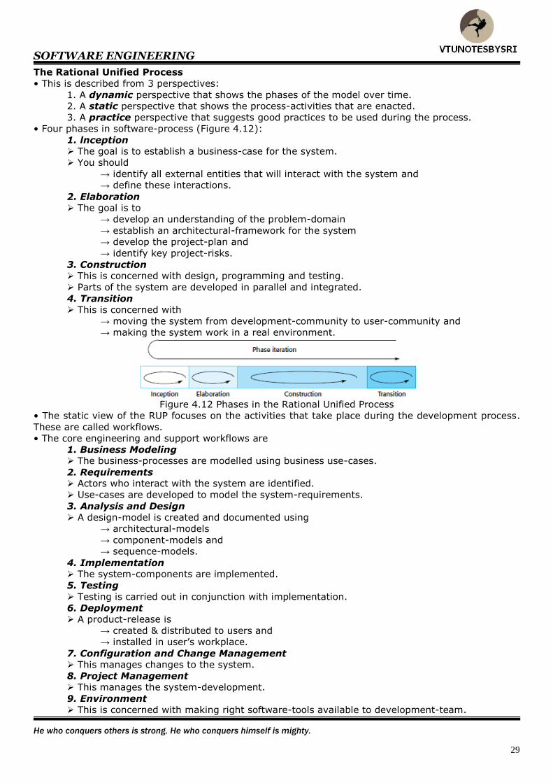
• Four phases in software-process (Figure 4.12):
1. lnception The goal is to establish a business-case for the system.
You should
→ identify all external entities that will interact with the system and
→ define these interactions.
2. Elaboration The goal is to
→ develop an understanding of the problem-domain
→ establish an architectural-framework for the system
→ develop the project-plan and
→ identify key project-risks.
3. Construction This is concerned with design, programming and testing.
Parts of the system are developed in parallel and integrated.
4. Transition This is concerned with
→ moving the system from development-community to user-community and
→ making the system work in a real environment.
Figure 4.12 Phases in the Rational Unified Process
• The static view of the RUP focuses on the activities that take place during the development process.
These are called workflows.
• The core engineering and support workflows are
1. Business Modeling The business-processes are modelled using business use-cases.
2. Requirements Actors who interact with the system are identified.
Use-cases are developed to model the system-requirements.
3. Analysis and Design A design-model is created and documented using
→ architectural-models
→ component-models and
→ sequence-models.
4. Implementation The system-components are implemented.
5. Testing
Testing is carried out in conjunction with implementation.
6. Deployment A product-release is
→ created & distributed to users and
→ installed in user’s workplace.
7. Configuration and Change Management This manages changes to the system.
8. Project Management This manages the system-development.
9. Environment This is concerned with making right software-tools available to development-team.
SOFTWARE ENGINEERING
Success in the end erases all the mistakes along the way.
30
• Six best practices are recommended:
1. Develop Software Iteratively
Plan increments of the system based on customer-priorities.
Develop and deliver the highest priority system-features early in the development process.
2. Manage Requirements
Explicitly document the customer’s requirements and keep track of changes to these
requirements. Analyse the impact of changes on the system before accepting them.
3. Use Component-based Architectures Structure the system-architecture into components.
4. Visually Model Software Use graphical models to present static- and dynamic-views of the software.
5. Verify Software Quality Ensure that the software meets the organisational quality standard.
6. Control Changes to Software
Manage changes to the software using a change management-system and configuration-
management tools.
SOFTWARE ENGINEERING
Winners are ordinary people with extraordinary heart.
31
CASE
• CASE stands for Computer-Aided Software Engineering.
• CASE is a software used to support process-activities such as → requirements-engineering
→ design
→ program-development and
→ testing.
• CASE tools include → design editors
→ data dictionaries
→ compilers
→ debuggers and
→ system building tools.
• Five activities can be automated using CASE tools:
1. The development of graphical-models as part of
→ requirements-specification or
→ software-design.
2. Understanding a design using a data-dictionary.
3. Generation of user-interfaces from a graphical-description.
4. Program-debugging.
5. Translation of programs from an old version to a more recent version.
• Two limitations of CASE tools:
1. Existing CASE systems automate routine activities but attempts to exploit artificial
intelligence technology to provide support for design have not been successful.
2. In most organisations, SE is a team-activity. Software-engineers spend a lot of time
interacting with other team-members. CASE technology does not provide much support for this.
SOFTWARE ENGINEERING
The only difference between dreams and achievements is hard work.
32
CASE Classification
• This helps to understand
→ types of CASE tools and
→ CASE tool’s role in supporting process-activities.
• CASE tools can be classified from 3 perspectives (Figure 4.14 & 4.15):
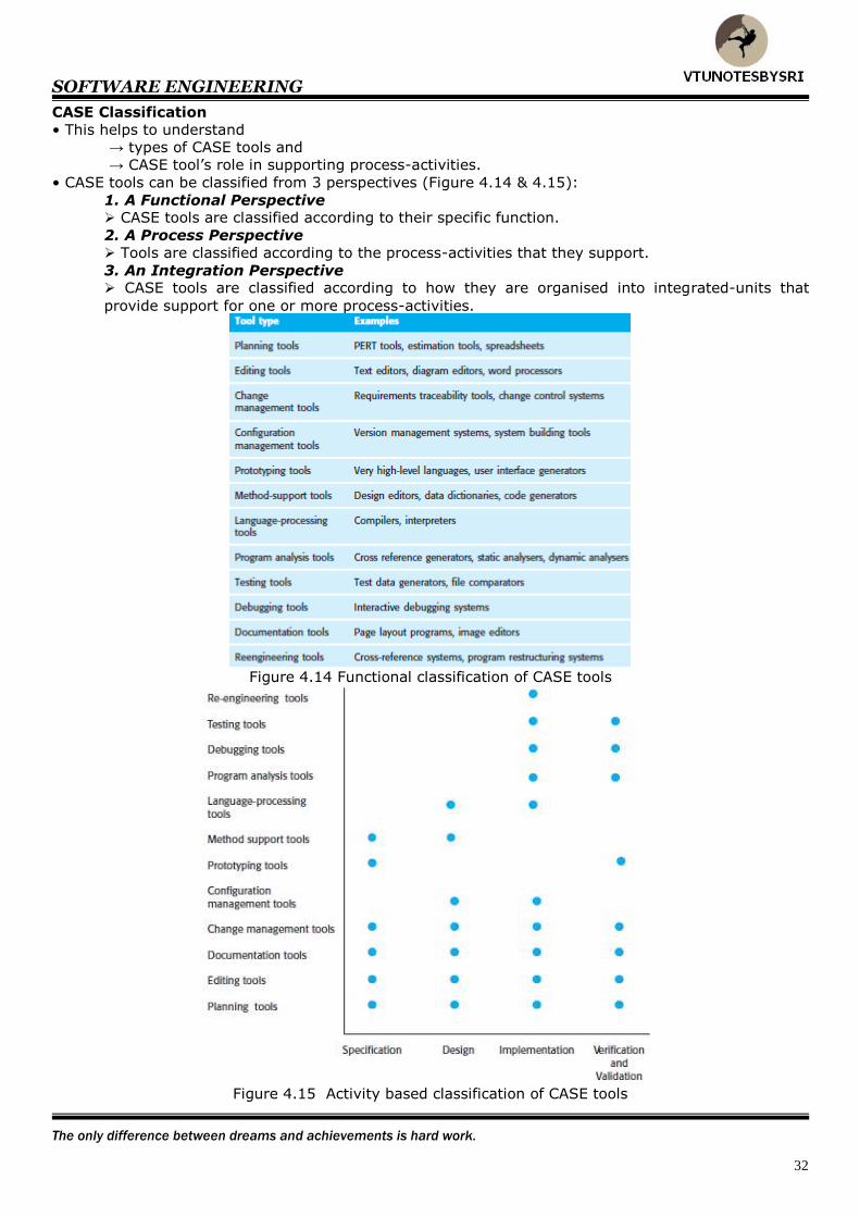
1. A Functional Perspective CASE tools are classified according to their specific function.
2. A Process Perspective
Tools are classified according to the process-activities that they support.
3. An Integration Perspective CASE tools are classified according to how they are organised into integrated-units that
provide support for one or more process-activities.
Figure 4.14 Functional classification of CASE tools
Figure 4.15 Activity based classification of CASE tools
SOFTWARE ENGINEERING
Live life with a fire that can never be extinguished.
33
UNIT 4: SYSTEM MODELS
System Model
• This is an abstraction of the system being studied.
• Why do we create a model?
Ans: To gain a better understanding of an entity.
For example, a model of a plane is a small plane.
• A software-model must be capable of representing:
1. Information that the software transforms.
2. Functions that enable the transformation to occur.
3. Behavior of the system as the transformation takes place.
• Five types of models:
1. Data- flow model This shows how data is processed at different stages in the system.
2. Composition model This shows how entities in the system are composed of other entities.
3. Architectural model This shows the principal subsystems that make up a system.
4. Classification model This shows how entities have common characteristics.
5. Stimulus-response model
This shows how the system reacts to internal and external events.
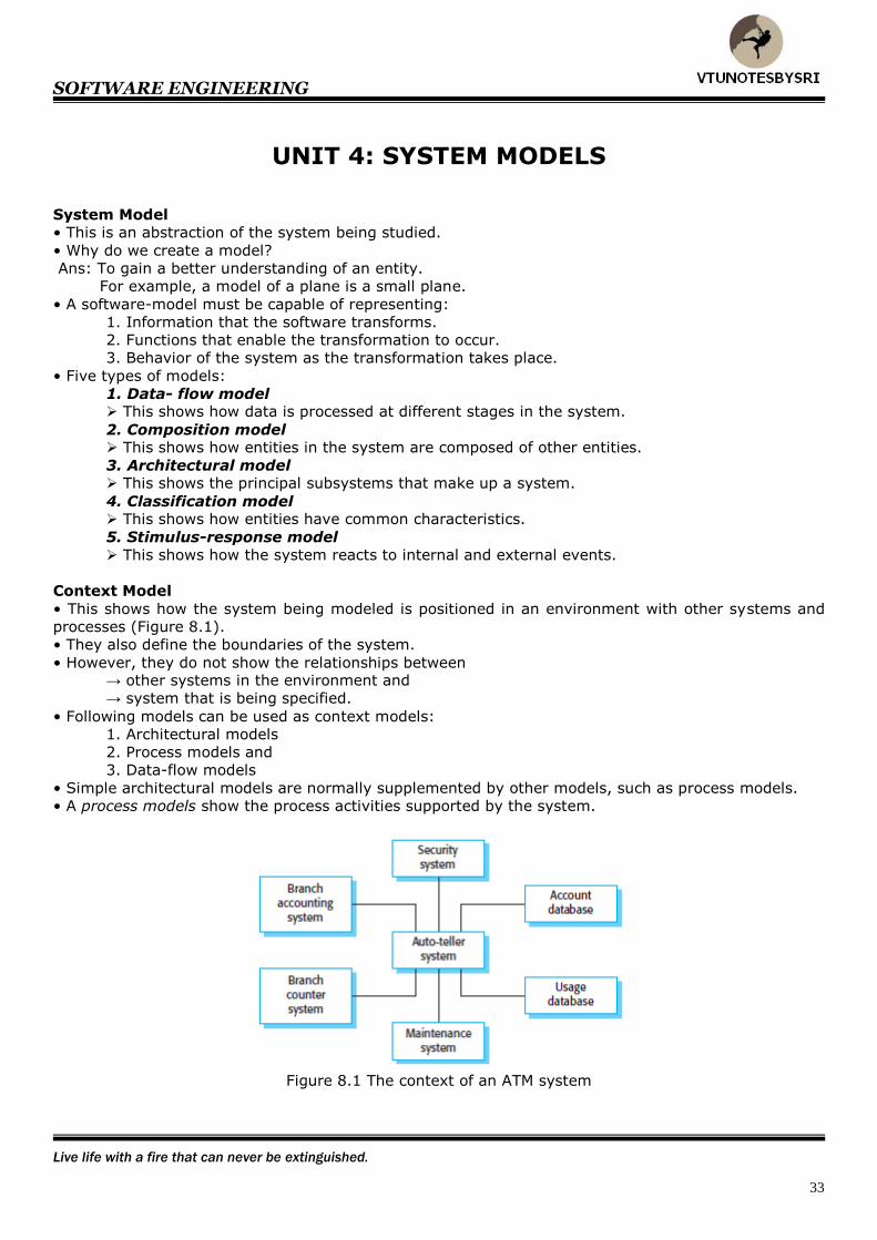
Context Model
• This shows how the system being modeled is positioned in an environment with other systems and
processes (Figure 8.1).
• They also define the boundaries of the system.
• However, they do not show the relationships between → other systems in the environment and
→ system that is being specified.
• Following models can be used as context models:
1. Architectural models
2. Process models and
3. Data-flow models
• Simple architectural models are normally supplemented by other models, such as process models.
• A process models show the process activities supported by the system.
Figure 8.1 The context of an ATM system
SOFTWARE ENGINEERING
You must have long-term goals to keep you from being frustrated by short-term failures.
34
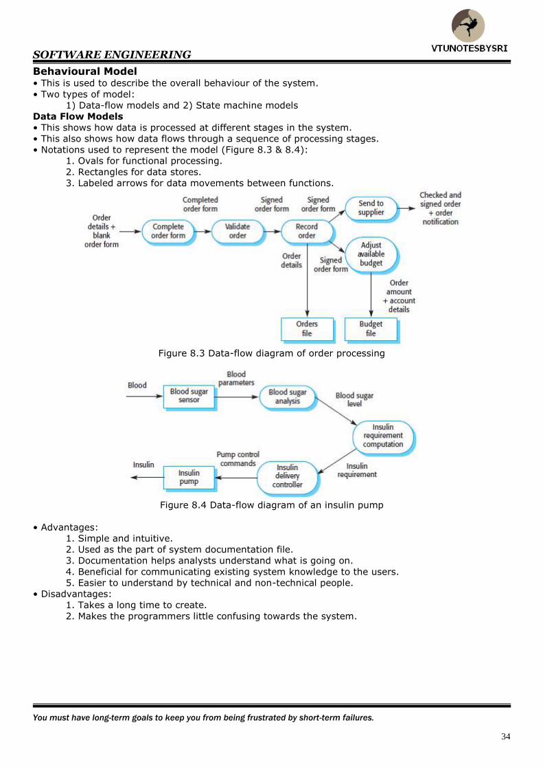
Behavioural Model • This is used to describe the overall behaviour of the system.
• Two types of model:
1) Data-flow models and 2) State machine models
Data Flow Models
• This shows how data is processed at different stages in the system.
• This also shows how data flows through a sequence of processing stages.
• Notations used to represent the model (Figure 8.3 & 8.4):
1. Ovals for functional processing.
2. Rectangles for data stores.
3. Labeled arrows for data movements between functions.
Figure 8.3 Data-flow diagram of order processing
Figure 8.4 Data-flow diagram of an insulin pump
• Advantages:
1. Simple and intuitive.
2. Used as the part of system documentation file.
3. Documentation helps analysts understand what is going on.
4. Beneficial for communicating existing system knowledge to the users.
5. Easier to understand by technical and non-technical people.
• Disadvantages:
1. Takes a long time to create.
2. Makes the programmers little confusing towards the system.

SOFTWARE ENGINEERING
There is no shortcut. Victory lies in overcoming obstacles every day.
35
State Machine Model
• This shows how the system reacts to internal & external events.
• This assumes that, at any time, the system is in one of the possible states.
• When a stimulus is received, this may trigger a transition to a different state.
• An event is something that affects the system.
• This does not show the flow of data within the system.
• This is used for modeling real-time systems.
• Statecharts are an integral part of the UML and are used to represent state machine models.
Statecharts
• Allow the decomposition of a model into sub-models (Figure 8.5).
• A brief description of the actions is included following the ‘do’ in each state.
• Can be complemented by tables describing the states and the stimuli.
Figure 8.5 State machine model of a simple microwave oven

SOFTWARE ENGINEERING
Innovate, develop, motivate, inspire, trust - be a leader.
36
Data Model
• This is used to describe the logical structure of data processed by the system. (Figure 8.7).
• Most commonly used technique is ERA model (Entity Relation Attribute).
• ERA model shows (Figure 8.8)
1. Data entities
2. Associated attributes and
3. Relations between these entities
• ER models are commonly used in database design.
• This can readily be implemented using relational databases
Figure 8.7 Microwave oven operation Figure 8.8 Semantic data model for the
L1BSYS system
• Drawback:
→ Like all graphical models, data models lack detail, and you should maintain more detailed
descriptions of the entities, relationships and attributes.
Solution:
→ You may collect the more detailed descriptions in a repository (called data dictionary).
• A data dictionary is an alphabetic-list of the names used in the system-models.
• The dictionary should also include
→ an associated description of the named-entity.
• If the name represents a composite-object, the dictionary should also include → description of the composition.
• Other information may also be included such as → date of creation and
→ name of creator.
• Advantages of using data dictionary:
1. It is a mechanism for name management. Many people may have to invent
→ names for entities and
→ relationships when developing a large system-model.
These names should be used consistently and should not clash.
2. It serves as a store of organizational information. As the system is developed, information that can link analysis, design & implementation is
added to the dictionary. Thus, all information about an entity is in one place.
SOFTWARE ENGINEERING
Life is built of the things we do. The only constructive material is positive action.
37
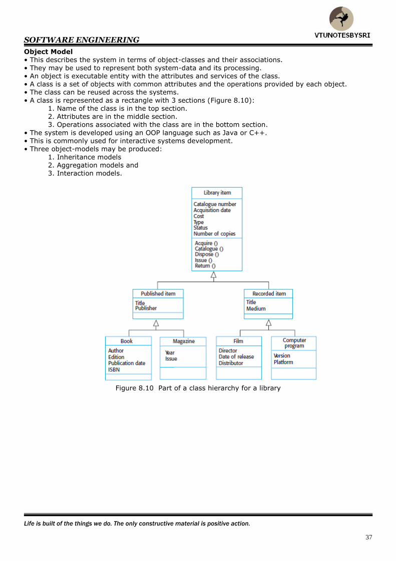
Object Model
• This describes the system in terms of object-classes and their associations.
• They may be used to represent both system-data and its processing.
• An object is executable entity with the attributes and services of the class.
• A class is a set of objects with common attributes and the operations provided by each object.
• The class can be reused across the systems.
• A class is represented as a rectangle with 3 sections (Figure 8.10):
1. Name of the class is in the top section.
2. Attributes are in the middle section.
3. Operations associated with the class are in the bottom section.
• The system is developed using an OOP language such as Java or C++.
• This is commonly used for interactive systems development.
• Three object-models may be produced:
1. Inheritance models
2. Aggregation models and
3. Interaction models.
Figure 8.10 Part of a class hierarchy for a library
SOFTWARE ENGINEERING
Always keep a window open in your mind for new ideas.
38
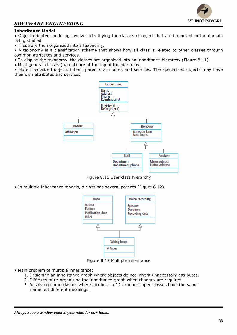
Inheritance Model
• Object-oriented modeling involves identifying the classes of object that are important in the domain
being studied.
• These are then organized into a taxonomy.
• A taxonomy is a classification scheme that shows how all class is related to other classes through
common attributes and services.
• To display the taxonomy, the classes are organised into an inheritance-hierarchy (Figure 8.11).
• Most general classes (parent) are at the top of the hierarchy.
• More specialized objects inherit parent’s attributes and services. The specialized objects may have
their own attributes and services.
Figure 8.11 User class hierarchy
• In multiple inheritance models, a class has several parents (Figure 8.12).
Figure 8.12 Multiple inheritance
• Main problem of multiple inheritance:
1. Designing an inheritance-graph where objects do not inherit unnecessary attributes.
2. Difficulty of re-organizing the inheritance-graph when changes are required.
3. Resolving name clashes where attributes of 2 or more super-classes have the same
name but different meanings.
SOFTWARE ENGINEERING
Keys to success: Research your ideas, plan for success, expect success, and just do it.
39
Object Aggregation
• An object is an aggregate of a set of other objects (Figure 8.13).
• The classes representing these objects may be modeled using an object aggregation model.
Figure 8.13 Aggregate object representing a course
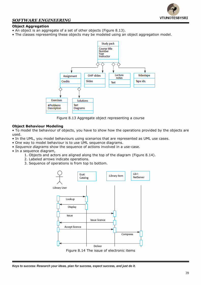
Object Behaviour Modeling
• To model the behaviour of objects, you have to show how the operations provided by the objects are
used.
• In the UML, you model behaviours using scenarios that are represented as UML use cases.
• One way to model behaviour is to use UML sequence diagrams.
• Sequence diagrams show the sequence of actions involved in a use-case.
• In a sequence diagram,
1. Objects and actors are aligned along the top of the diagram (Figure 8.14).
2. Labeled arrows indicate operations.
3. Sequence of operations is from top to bottom.
Figure 8.14 The issue of electronic items
SOFTWARE ENGINEERING
Every success is built on the ability to do better than good enough.
40
Structured Method
• This is a systematic way of producing models of a system that is to be built.
• They have their own preferred set of system-models.
• They usually define → a process that may be used to derive the system-models and
→ a set of rules that apply to the models.
• Standard documentation is produced for the system.
• CASE tools are usually available for method-support.
• CASE tools support → model editing and
→ code & report generation.
• Advantages:
1 They have been applied successfully in many large projects.
2. They can deliver significant cost reductions.
3. They ensure that standard design documentation is produced.
• Disadvantages:
1. They do not provide effective support for modelling non-functional system-requirements.
2. They often produce too much documentation.
3. The models that are produced are very detailed, and users often find them difficult to
understand.
4. They do not usually include guidelines to help users decide whether a method is appropriate
for a particular problem.
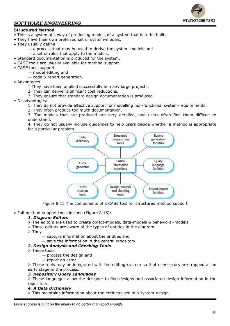
Figure 8.15 The components of a CASE tool for structured method support
• Full method-support tools include (Figure 8.15):
1. Diagram Editors The editors are used to create object-models, data-models & behavioral-models.
These editors are aware of the types of entities in the diagram.
They
→ capture information about the entities and
→ save the information in the central repository.
2. Design Analysis and Checking Tools These tools
→ process the design and
→ report on error.
These tools may be integrated with the editing-system so that user-errors are trapped at an
early stage in the process.
3. Repository Query Languages These languages allow the designer to find designs and associated design-information in the
repository.
4. A Data Dictionary This maintains information about the entities used in a system-design.

SOFTWARE ENGINEERING
The only thing you have to fear is not giving 100%.
41
5. Report Definition and Generation Tools These tools
→ take information from the central-store and
→ automatically generate system-documentation.
6. Forms Definition Tools These tools allow screen and document formats to be specified.
7. Import/Export Facilities These allow the interchange of information from the central-store with other development
tools.
8. Code Generators These generate code (or code-skeletons) automatically from the design captured in the
central-store.
SOFTWARE ENGINEERING
It’s in your moments of decision that your destiny is shaped.
42
UNIT 4(CONT.): PROJECT MANAGEMENT
Project Management
• This is concerned with activities involved in ensuring that software is delivered on time and on
schedule.
• Why do we need project management?
Ans: Software engineering is subject to organizational-budget and schedule-constraints.
Project managers ensure that software meets these constraints
How is software engineering different?
1. The product is intangible
• Software cannot be seen or touched.
• Project-managers cannot see progress of the project.
• The managers rely on others to produce the documentation needed to review progress.
2. There are no standard software-processes
• Software-processes vary severely from one organisation to another.
• We still cannot reliably predict when a particular software-process is likely to cause problems.
3. Large software projects are often ‘one-off’ projects
• Large-projects are usually different in some ways from previous-projects.
• Due to rapid technological changes in computers, manager’s experience may become obsolete.
Management Activities
1. Proposal Writing
• The proposal describes
1. Objectives of the project
2. How the objectives will be carried out
• The proposal usually includes cost- and schedule-estimates.
2. Project Planning and Scheduling
• Project planning is concerned with identifying the activities, milestones and deliverables produced by
a project.
• A plan is drawn up to guide the development towards the project-goals.
3. Project cost
• Cost estimation is concerned with estimating the resources required to accomplish the project-plan.
4. Project Monitoring and Reviews
• The manager must → keep track of the progress of the project and
→ compare actual & planned progress.
• Project reviews are concerned with → reviewing overall progress of the project and
→ checking whether the project and the goals of the organization are aligned.
5. Personnel Selection and Evaluation
• Project-managers usually have to select people to work on their project.
• Managers have to settle for a less-than-ideal project-team. The reasons for this are:
1. The project-budget may not cover the use of highly paid staff.
2. Staff with the appropriate experience may not be available.
3. The organisation may wish to develop the skills of its employees.
6. Report Writing and Presentations
• Project managers are usually responsible for reporting on the project to both the client and
contractor organisations.
• They have to write brief documents that abstract critical information from detailed project reports.

SOFTWARE ENGINEERING
Reach for the moon. If you fall short at least you'll be among the stars.
43
Project Planning
• This is concerned with identifying the activities, milestones and deliverables produced by the project.
• A plan is drawn up to guide the development towards the project-goals (Figure 5.1).
• Planning is an iterative process, which is only complete when the project itself is complete.
• As project-information becomes available during the project, the plan should be regularly revised.
• At the beginning, you should assess the constraints (staff available & overall budget) affecting the
project.
• Project managers should estimate project parameters such as its structure, size, and distribution of
functions.
Figure 5.1 Project planning
Figure 5.2 Types of plan
SOFTWARE ENGINEERING
The greatest glory in living lies not in never falling, but in rising every time we fall.
44
The Project Plan
1. Introduction
• This
→ describes the objectives of the project and
→ sets out the constraints e.g. budget, time
2. Project Organisation
• This describes
→ the way in which the project-team is organized and
→ People involved with their roles.
3. Risk Analysis
• This describes
→ possible project risks
→ likelihood of the risks arising and
→ risk reduction strategies.
4. Hardware and Software Resource Requirements
• This specifies the hardware and the support-software required to carry out the development.
• If hardware has to be bought, estimates of the prices and the delivery-schedule may be included.
5. Work Breakdown
• This
→ sets out the breakdown of the project into activities and
→ identifies the milestones & deliverables associated with each activity.
6. Project Schedule
• This shows the dependencies between
1. Activities
2. Estimated time required to reach each milestone and
3. Allocation of people to activities
7. Monitoring and Reporting Mechanisms
• This defines the management-reports that should be produced and the project-monitoring
mechanisms used.
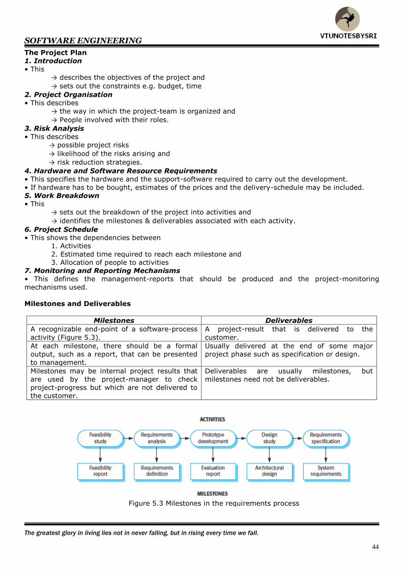
Milestones and Deliverables
Milestones Deliverables
A recognizable end-point of a software-process
activity (Figure 5.3).
A project-result that is delivered to the
customer.
At each milestone, there should be a formal
output, such as a report, that can be presented
to management.
Usually delivered at the end of some major
project phase such as specification or design.
Milestones may be internal project results that
are used by the project-manager to check
project-progress but which are not delivered to
the customer.
Deliverables are usually milestones, but
milestones need not be deliverables.
Figure 5.3 Milestones in the requirements process

SOFTWARE ENGINEERING
Focus on where you want to go, not where your currently are.
45
Project Scheduling
• The basic idea is
1. Separate the total work involved in a project into separate activities.
2. Then, judge the time required to complete these activities (Figure 5.4).
• Usually, some of these activities are carried out in parallel.
• Project-activities should normally last at least a week.
Figure 5.4 The project scheduling process
• When estimating schedules, project-manager should not assume that every stage of the project will
be problem-free. This is because
1. People working on a project may fall ill or may leave.
2. Hardware may break down.
3. Essential software may be delivered late.
• Project manager also have to estimate the resources needed to complete each task.
• The principal resource is the human-effort required. Other resources may be
1. Disk-space required on a server.
2. Time required on specialized hardware.
3. Travel-budget required for project-staff.
SOFTWARE ENGINEERING
Success is not where you are in life, but the obstacles you have overcome.
46
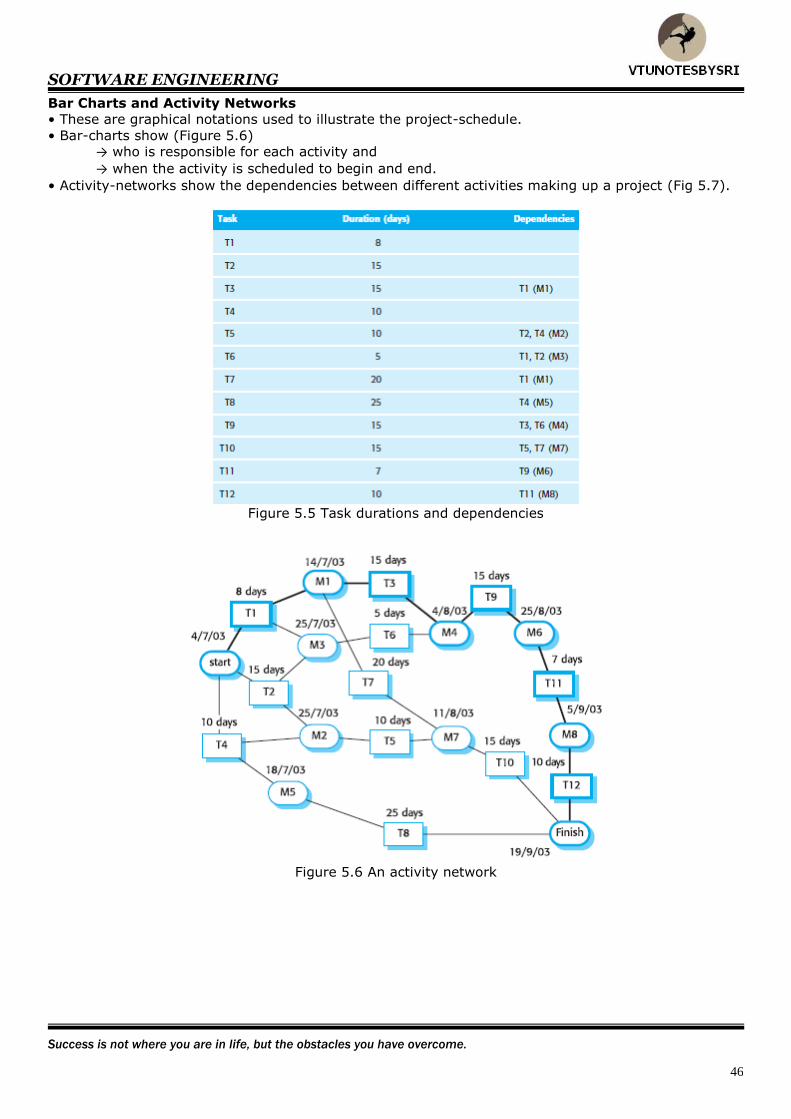
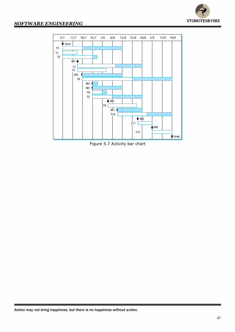
Bar Charts and Activity Networks
• These are graphical notations used to illustrate the project-schedule.
• Bar-charts show (Figure 5.6)
→ who is responsible for each activity and
→ when the activity is scheduled to begin and end.
• Activity-networks show the dependencies between different activities making up a project (Fig 5.7).
Figure 5.5 Task durations and dependencies
Figure 5.6 An activity network
SOFTWARE ENGINEERING
Action may not bring happiness, but there is no happiness without action.
47
Figure 5.7 Activity bar chart
SOFTWARE ENGINEERING
We cannot always control what goes on outside, but we can control what goes on inside.
48
Risk Management
• The basic idea is
1. Identify possible risks.
2. Then, draw up plans to minimize their effect on a project (Figure 5.9).
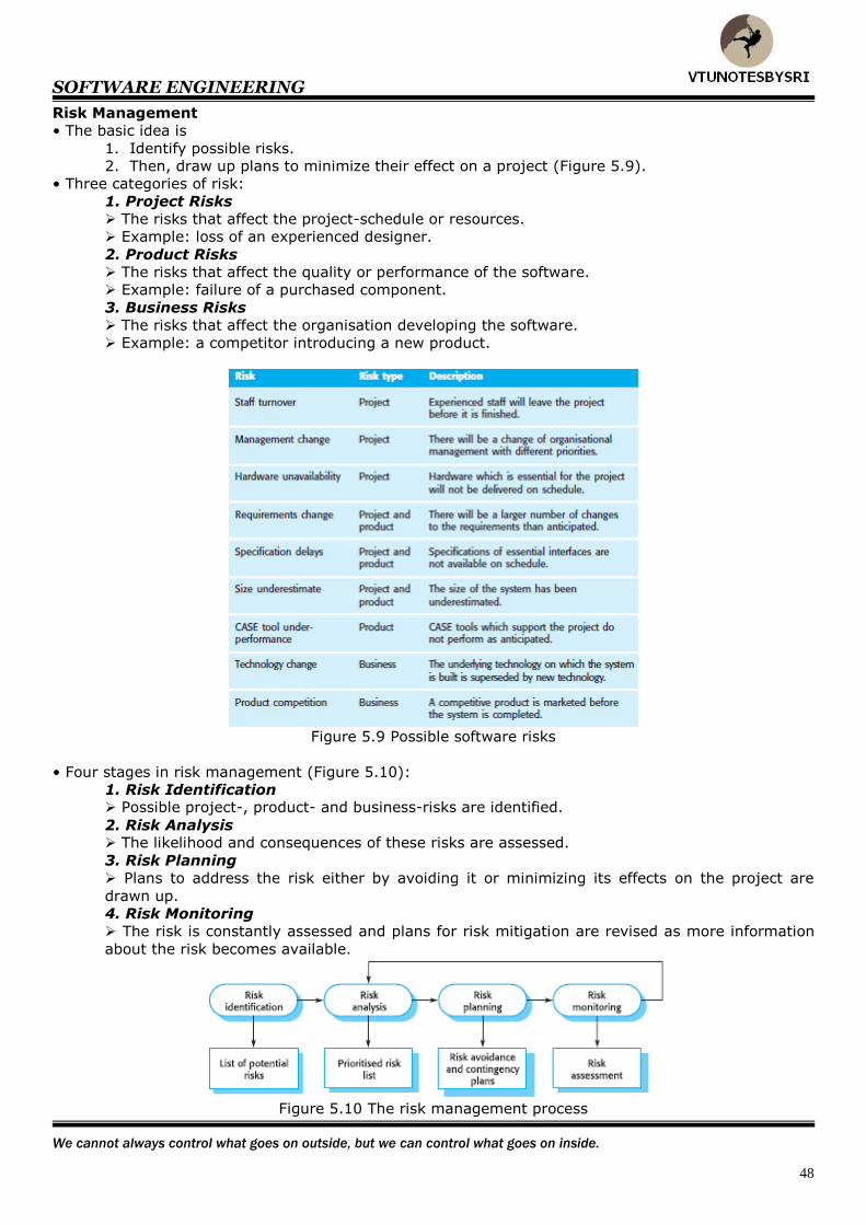
• Three categories of risk:
1. Project Risks
The risks that affect the project-schedule or resources.
Example: loss of an experienced designer.
2. Product Risks
The risks that affect the quality or performance of the software.
Example: failure of a purchased component.
3. Business Risks
The risks that affect the organisation developing the software.
Example: a competitor introducing a new product.
Figure 5.9 Possible software risks
• Four stages in risk management (Figure 5.10):
1. Risk Identification Possible project-, product- and business-risks are identified.
2. Risk Analysis The likelihood and consequences of these risks are assessed.
3. Risk Planning
Plans to address the risk either by avoiding it or minimizing its effects on the project are
drawn up.
4. Risk Monitoring
The risk is constantly assessed and plans for risk mitigation are revised as more information
about the risk becomes available.
Figure 5.10 The risk management process

SOFTWARE ENGINEERING
You must learn from your past mistakes, but not lean on your past successes.
49
Risk Identification
• This is concerned with discovering possible risks to the project.
• Six types of risk (Figure 5.11):
1. Technology Risks Risks that derive from the software/hardware technologies that are used to develop the
system.
2. People Risks Risks that is associated with the people in the development-team.
3. Organisational Risks
Risks that derive from the organisational environment where the software is being developed.
4. Tools Risks Risks that derive from the CASE tools & other support software used to develop the system.
5. Requirements Risks Risks that derive from changes to the customer-requirements and the process of managing
the requirements change.
6. Estimation Risks Risks that derive from
→ management estimates of the system characteristics and
→ resources required to build the system.
Figure 5.11 Risks and risk types
Risk Monitoring
• This involves regularly assessing each of the identified risks to decide whether or not that risk is
becoming more or less probable (Figure 5.14).
Figure 5.14 Risk factors

SOFTWARE ENGINEERING
There are essentially two things that will make us wiser: the books we read and the people we meet.
50
Risk Planning
• The basic idea is
1. Consider each of the key risks that have been identified and
2. Then, identify strategies to manage the risk (Figure 5.12).
Figure 5.12 Risk analysis
• Three categories of strategies (Figure 5.13:
1. Avoidance Strategies The probability that the risk will arise will be reduced.
Example: strategy for dealing with defective components.
2. Minimization Strategies The impact of the risk will be reduced.
Example: staff illness.
3. Contingency Plans You are prepared for the worst and have a strategy in place to deal with it.
Example: strategy for financial problems.
Figure 5.13 Risk management strategies
SOFTWARE ENGINEERING
Spectacular achievement is always preceded by painstaking preparation.
51
UNIT 5: ARCHITECTURAL DESIGN
Architectural design
• This is an early stage of the system-design process.
• This is a link between 1) specification and 2) design-processes.
• This involves identifying major system components and their communications.
• The output of the architectural-design process is a description of the software-architecture.
Why do we need architectural design?
1. Stakeholder Communication
• Architecture may be used as a focus of discussion by different stakeholders.
2. System Analysis
• Architectural-design decisions have a strong effect on whether the system can meet critical
requirements such as → performance
→ reliability and
→ maintainability.
3. Large-scale reuse
• The architecture may be reusable across a range of systems.
Non-Functional System Requirements
1. Performance
• Localize critical-operations within a small number of subsystems.
• Minimize communications between the subsystems.
2. Security
• Use a layered architecture with critical-assets in the inner layers.
• A high level of security-validation must be applied to the inner layers
3. Safety
• Localize safety critical-operations within a small number of subsystems.
• This reduces the costs and problems of safety-validation.
4. Availability
• Include → redundant-components and
→ mechanisms for fault-tolerance.
• It should be possible to replace and update components without stopping the system.
5. Maintainability
• Use fine-grain, self-contained components that may readily be changed.
• Producers of data should be separated from consumers.
• Shared data-structures should be avoided.

SOFTWARE ENGINEERING
The toughest part of working up the ladder is fighting through the crowd at the bottom.
52
Architectural Design Decisions
• In architectural design, system-architects try to establish a system-organization that will satisfy the
functional and non-functional requirements.
• The software-architect must make decisions about → system organisation style
→ decomposition style &
→ control style.
• Evaluating different architectures for software is sometimes refereed to as trade off analysis.
• System-architect has to answer following basic questions:
1. Is there a generic-architecture (i.e. waterfall or spiral) that can act as a template for the
system that is being designed?
2. How will the system be decomposed into modules?
3. What architectural style is appropriate?
4. What basic approach is used to structure the system?
5. How will the structural-units be decomposed into modules?
6. What strategy will be used to control the operation of the units?
7. How will the architectural-design be evaluated?
8. How should the architecture be documented?
• The architecture of a system may be based on a particular architectural-model.
• An architectural-style is a pattern of system-organisation such as → client-server organisation or
→ layered architecture.
• Architectural-models developed include:
1. Static Structural Model This shows the subsystems that are to be developed as separate units.
2. Dynamic Process Model This shows how the system is organised into processes at run-time.
3. Interface Model
This defines the services offered by each subsystem through its public-interface.
4. Relationship Models This shows relationships, such as data-flow, between the subsystems.
5. Distribution Model This shows how subsystems may be distributed across computers.
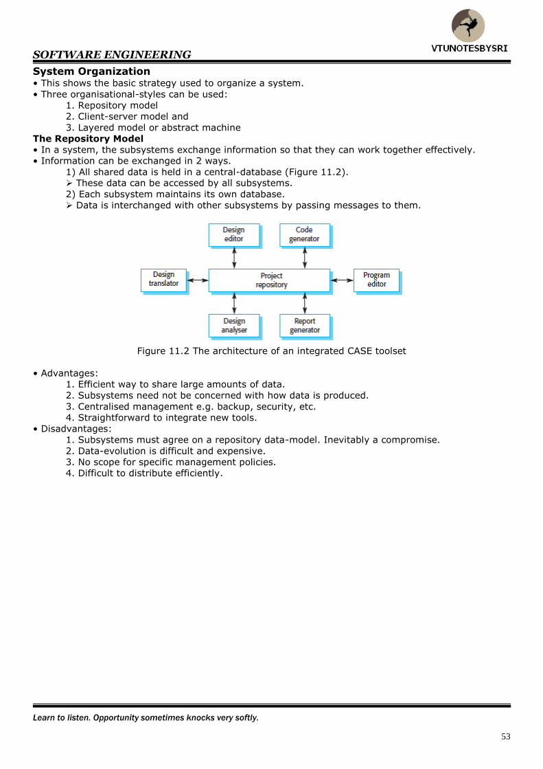
SOFTWARE ENGINEERING
Learn to listen. Opportunity sometimes knocks very softly.
53
System Organization • This shows the basic strategy used to organize a system.
• Three organisational-styles can be used:
1. Repository model
2. Client-server model and
3. Layered model or abstract machine
The Repository Model
• In a system, the subsystems exchange information so that they can work together effectively.
• Information can be exchanged in 2 ways.
1) All shared data is held in a central-database (Figure 11.2). These data can be accessed by all subsystems.
2) Each subsystem maintains its own database.
Data is interchanged with other subsystems by passing messages to them.
Figure 11.2 The architecture of an integrated CASE toolset
• Advantages:
1. Efficient way to share large amounts of data.
2. Subsystems need not be concerned with how data is produced.
3. Centralised management e.g. backup, security, etc.
4. Straightforward to integrate new tools.
• Disadvantages:
1. Subsystems must agree on a repository data-model. Inevitably a compromise.
2. Data-evolution is difficult and expensive.
3. No scope for specific management policies.
4. Difficult to distribute efficiently.
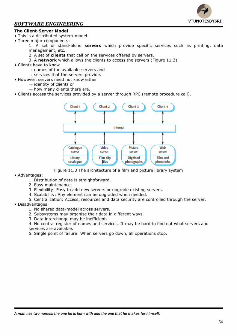
SOFTWARE ENGINEERING
A man has two names: the one he is born with and the one that he makes for himself.
54
The Client-Server Model
• This is a distributed system-model.
• Three major components:
1. A set of stand-alone servers which provide specific services such as printing, data
management, etc.
2. A set of clients that call on the services offered by servers.
3. A network which allows the clients to access the servers (Figure 11.3).
• Clients have to know → names of the available-servers and
→ services that the servers provide.
• However, servers need not know either → identity of clients or
→ how many clients there are.
• Clients access the services provided by a server through RPC (remote procedure call).
Figure 11.3 The architecture of a film and picture library system
• Advantages:
1. Distribution of data is straightforward.
2. Easy maintenance.
3. Flexibility: Easy to add new servers or upgrade existing servers.
4. Scalability: Any element can be upgraded when needed.
5. Centralization: Access, resources and data security are controlled through the server.
• Disadvantages:
1. No shared data-model across servers.
2. Subsystems may organise their data in different ways.
3. Data interchange may be inefficient.
4. No central register of names and services. It may be hard to find out what servers and
services are available.
5. Single point of failure: When servers go down, all operations stop.
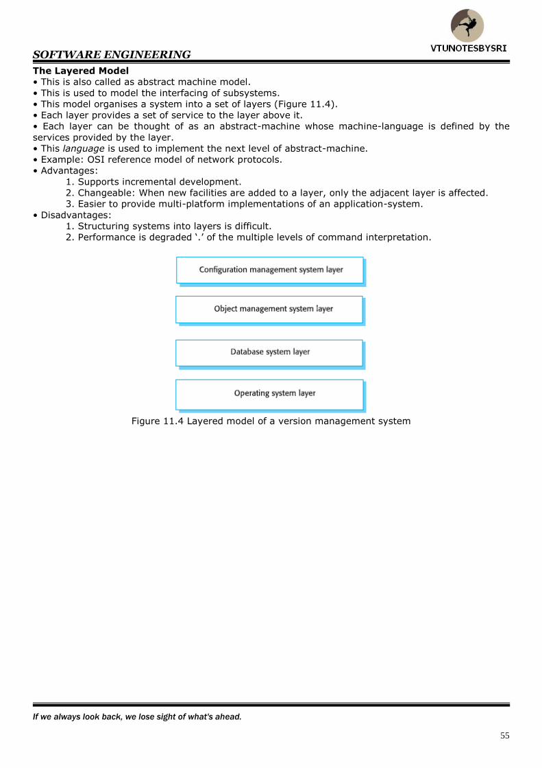
SOFTWARE ENGINEERING
If we always look back, we lose sight of what's ahead.
55
The Layered Model
• This is also called as abstract machine model.
• This is used to model the interfacing of subsystems.
• This model organises a system into a set of layers (Figure 11.4).
• Each layer provides a set of service to the layer above it.
• Each layer can be thought of as an abstract-machine whose machine-language is defined by the
services provided by the layer.
• This language is used to implement the next level of abstract-machine.
• Example: OSI reference model of network protocols.
• Advantages:
1. Supports incremental development.
2. Changeable: When new facilities are added to a layer, only the adjacent layer is affected.
3. Easier to provide multi-platform implementations of an application-system.
• Disadvantages:
1. Structuring systems into layers is difficult.
2. Performance is degraded ‘.’ of the multiple levels of command interpretation.
Figure 11.4 Layered model of a version management system
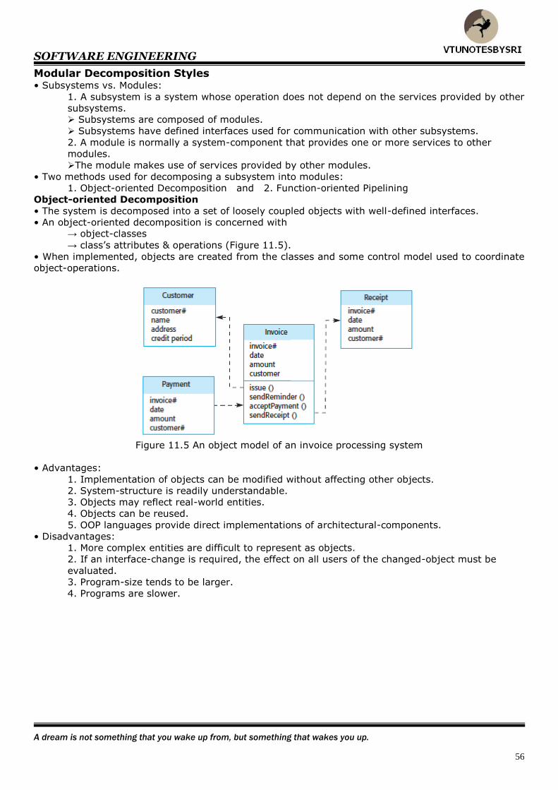
SOFTWARE ENGINEERING
A dream is not something that you wake up from, but something that wakes you up.
56
Modular Decomposition Styles • Subsystems vs. Modules:
1. A subsystem is a system whose operation does not depend on the services provided by other
subsystems. Subsystems are composed of modules.
Subsystems have defined interfaces used for communication with other subsystems.
2. A module is normally a system-component that provides one or more services to other
modules.
The module makes use of services provided by other modules.
• Two methods used for decomposing a subsystem into modules:
1. Object-oriented Decomposition and 2. Function-oriented Pipelining
Object-oriented Decomposition
• The system is decomposed into a set of loosely coupled objects with well-defined interfaces.
• An object-oriented decomposition is concerned with → object-classes
→ class’s attributes & operations (Figure 11.5).
• When implemented, objects are created from the classes and some control model used to coordinate
object-operations.
Figure 11.5 An object model of an invoice processing system
• Advantages:
1. Implementation of objects can be modified without affecting other objects.
2. System-structure is readily understandable.
3. Objects may reflect real-world entities.
4. Objects can be reused.
5. OOP languages provide direct implementations of architectural-components.
• Disadvantages:
1. More complex entities are difficult to represent as objects.
2. If an interface-change is required, the effect on all users of the changed-object must be
evaluated.
3. Program-size tends to be larger.
4. Programs are slower.
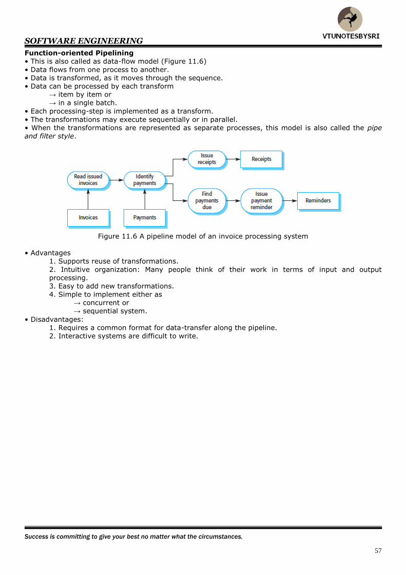
SOFTWARE ENGINEERING
Success is committing to give your best no matter what the circumstances.
57
Function-oriented Pipelining
• This is also called as data-flow model (Figure 11.6)
• Data flows from one process to another.
• Data is transformed, as it moves through the sequence.
• Data can be processed by each transform → item by item or
→ in a single batch.
• Each processing-step is implemented as a transform.
• The transformations may execute sequentially or in parallel.
• When the transformations are represented as separate processes, this model is also called the pipe
and filter style.
Figure 11.6 A pipeline model of an invoice processing system
• Advantages
1. Supports reuse of transformations.
2. Intuitive organization: Many people think of their work in terms of input and output
processing.
3. Easy to add new transformations.
4. Simple to implement either as
→ concurrent or
→ sequential system.
• Disadvantages:
1. Requires a common format for data-transfer along the pipeline.
2. Interactive systems are difficult to write.
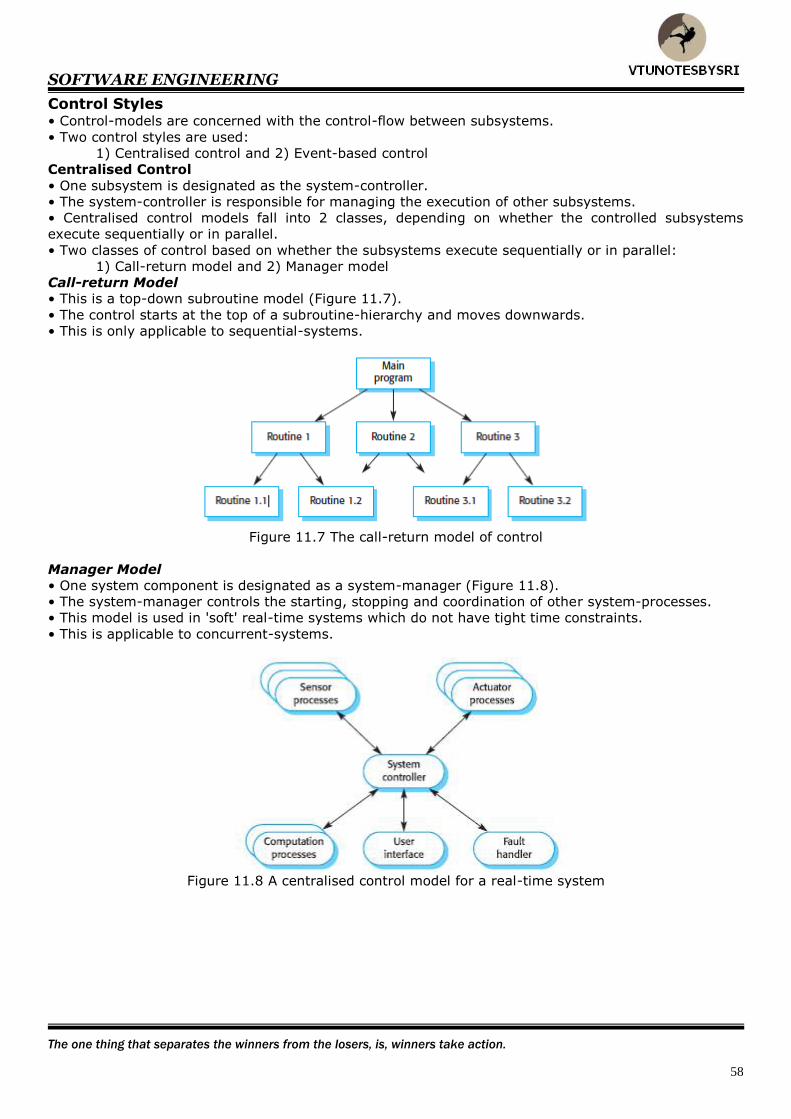
SOFTWARE ENGINEERING
The one thing that separates the winners from the losers, is, winners take action.
58
Control Styles • Control-models are concerned with the control-flow between subsystems.
• Two control styles are used:
1) Centralised control and 2) Event-based control
Centralised Control
• One subsystem is designated as the system-controller.
• The system-controller is responsible for managing the execution of other subsystems.
• Centralised control models fall into 2 classes, depending on whether the controlled subsystems
execute sequentially or in parallel.
• Two classes of control based on whether the subsystems execute sequentially or in parallel:
1) Call-return model and 2) Manager model
Call-return Model
• This is a top-down subroutine model (Figure 11.7).
• The control starts at the top of a subroutine-hierarchy and moves downwards.
• This is only applicable to sequential-systems.
Figure 11.7 The call-return model of control
Manager Model
• One system component is designated as a system-manager (Figure 11.8).
• The system-manager controls the starting, stopping and coordination of other system-processes.
• This model is used in 'soft' real-time systems which do not have tight time constraints.
• This is applicable to concurrent-systems.
Figure 11.8 A centralised control model for a real-time system
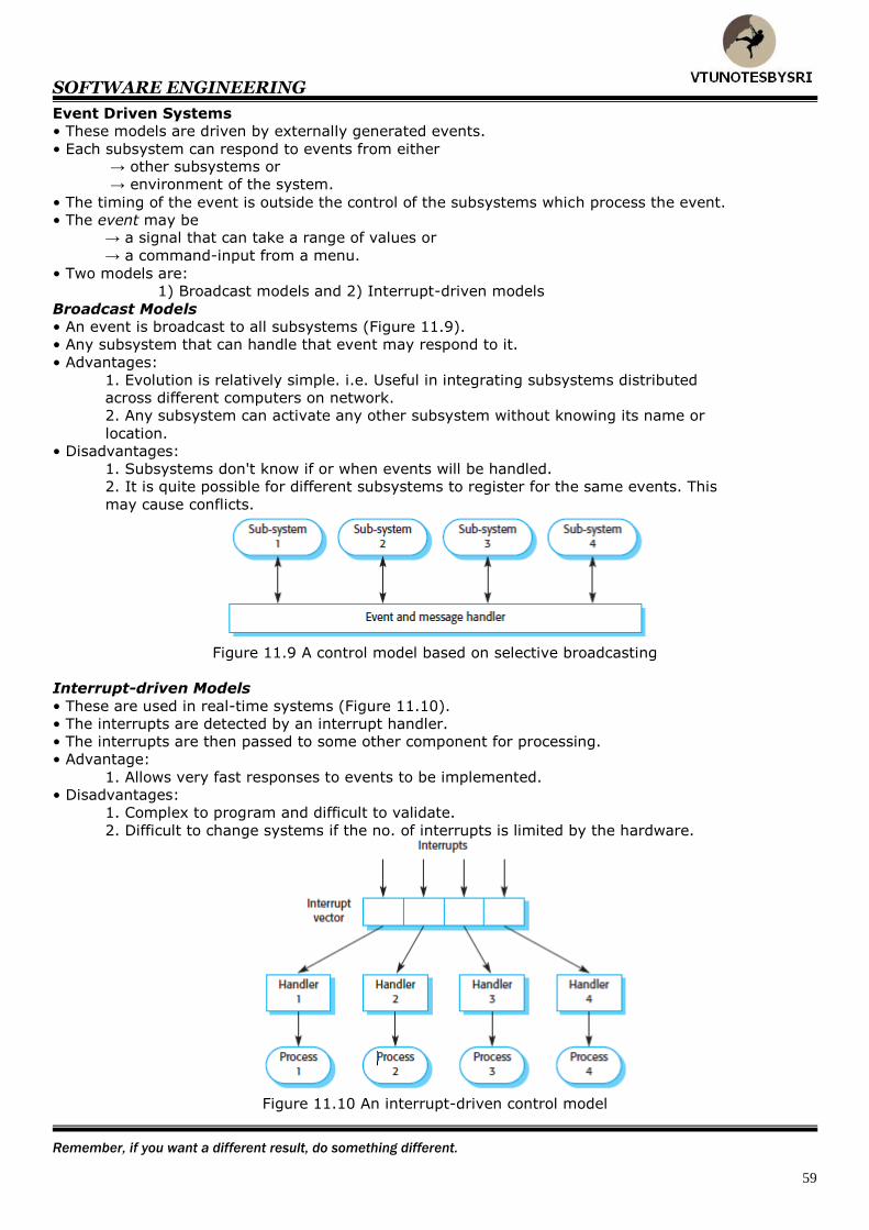
SOFTWARE ENGINEERING
Remember, if you want a different result, do something different.
59
Event Driven Systems
• These models are driven by externally generated events.
• Each subsystem can respond to events from either → other subsystems or
→ environment of the system.
• The timing of the event is outside the control of the subsystems which process the event.
• The event may be → a signal that can take a range of values or
→ a command-input from a menu.
• Two models are:
1) Broadcast models and 2) Interrupt-driven models
Broadcast Models
• An event is broadcast to all subsystems (Figure 11.9).
• Any subsystem that can handle that event may respond to it.
• Advantages:
1. Evolution is relatively simple. i.e. Useful in integrating subsystems distributed
across different computers on network.
2. Any subsystem can activate any other subsystem without knowing its name or
location.
• Disadvantages:
1. Subsystems don't know if or when events will be handled.
2. It is quite possible for different subsystems to register for the same events. This
may cause conflicts.
Figure 11.9 A control model based on selective broadcasting
Interrupt-driven Models
• These are used in real-time systems (Figure 11.10).
• The interrupts are detected by an interrupt handler.
• The interrupts are then passed to some other component for processing.
• Advantage:
1. Allows very fast responses to events to be implemented.
• Disadvantages:
1. Complex to program and difficult to validate.
2. Difficult to change systems if the no. of interrupts is limited by the hardware.
Figure 11.10 An interrupt-driven control model

SOFTWARE ENGINEERING
You are successful the moment you start moving toward a worthwhile goal.
60
Reference Architectures
• The common architectural structure can be reused when developing new systems. These
architectural models are called domain specific architectures (Figure 11.11).
Figure 11.11 The 051 reference model architecture
• Two types of model:
1. Generic Models These are abstractions from a number of real-systems.
They encapsulate the major features of the real-systems.
2. Reference Models These are more abstract and describe a larger class of systems.
These models are usually derived from a study of the application-domain.
• Five levels of service (Figure 11.12):
1. Data Repository Services These provide facilities for the storage & management of data and their relationships.
2. Data Integration Services
These provide facilities for
→ managing groups or
→ establishment of relationships between the groups.
These services and data repository services are the basis of data-integration in the
environment.
3. Task Management Services These provide facilities for the definition of process-models.
They support process-integration.
4. Message Services These provide facilities for
→ tool-tool communication
→ environment-tool communication and
→ environment-environment communication.
They support control-integration.
5. User interface Services These provide facilities for user-interface development.
They support presentation-integration.
Figure 11.12 The ECMA reference architecture for CASE environments
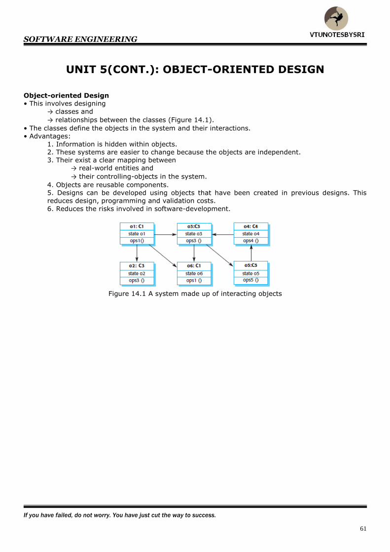
SOFTWARE ENGINEERING
If you have failed, do not worry. You have just cut the way to success.
61
UNIT 5(CONT.): OBJECT-ORIENTED DESIGN
Object-oriented Design
• This involves designing
→ classes and
→ relationships between the classes (Figure 14.1).
• The classes define the objects in the system and their interactions.
• Advantages:
1. Information is hidden within objects.
2. These systems are easier to change because the objects are independent.
3. Their exist a clear mapping between
→ real-world entities and
→ their controlling-objects in the system.
4. Objects are reusable components.
5. Designs can be developed using objects that have been created in previous designs. This
reduces design, programming and validation costs.
6. Reduces the risks involved in software-development.
Figure 14.1 A system made up of interacting objects
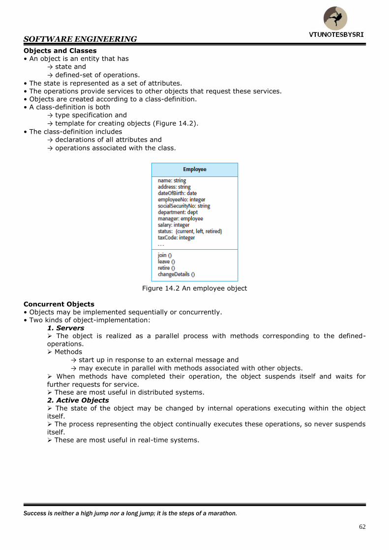
SOFTWARE ENGINEERING
Success is neither a high jump nor a long jump; it is the steps of a marathon.
62
Objects and Classes
• An object is an entity that has
→ state and
→ defined-set of operations.
• The state is represented as a set of attributes.
• The operations provide services to other objects that request these services.
• Objects are created according to a class-definition.
• A class-definition is both
→ type specification and
→ template for creating objects (Figure 14.2).
• The class-definition includes
→ declarations of all attributes and
→ operations associated with the class.
Figure 14.2 An employee object
Concurrent Objects
• Objects may be implemented sequentially or concurrently.
• Two kinds of object-implementation:
1. Servers The object is realized as a parallel process with methods corresponding to the defined-
operations.
Methods
→ start up in response to an external message and
→ may execute in parallel with methods associated with other objects.
When methods have completed their operation, the object suspends itself and waits for
further requests for service. These are most useful in distributed systems.
2. Active Objects
The state of the object may be changed by internal operations executing within the object
itself. The process representing the object continually executes these operations, so never suspends
itself. These are most useful in real-time systems.

SOFTWARE ENGINEERING
Achievement is largely the product of steadily raising one's levels of aspirations and expectations.
63
Object-oriented Design Process
• Object-oriented design has a no. of stages (Figure 14.6 & 14.7):
1. Understand and define the context and the modes of use of the system.
2. Design the system architecture.
3. Identify the principal objects in the system.
4. Develop design models.
5. Specify object interfaces.
Figure 14.6 Layered architecture for weather mapping system
Figure 14.7 Subsystems in the weather mapping system
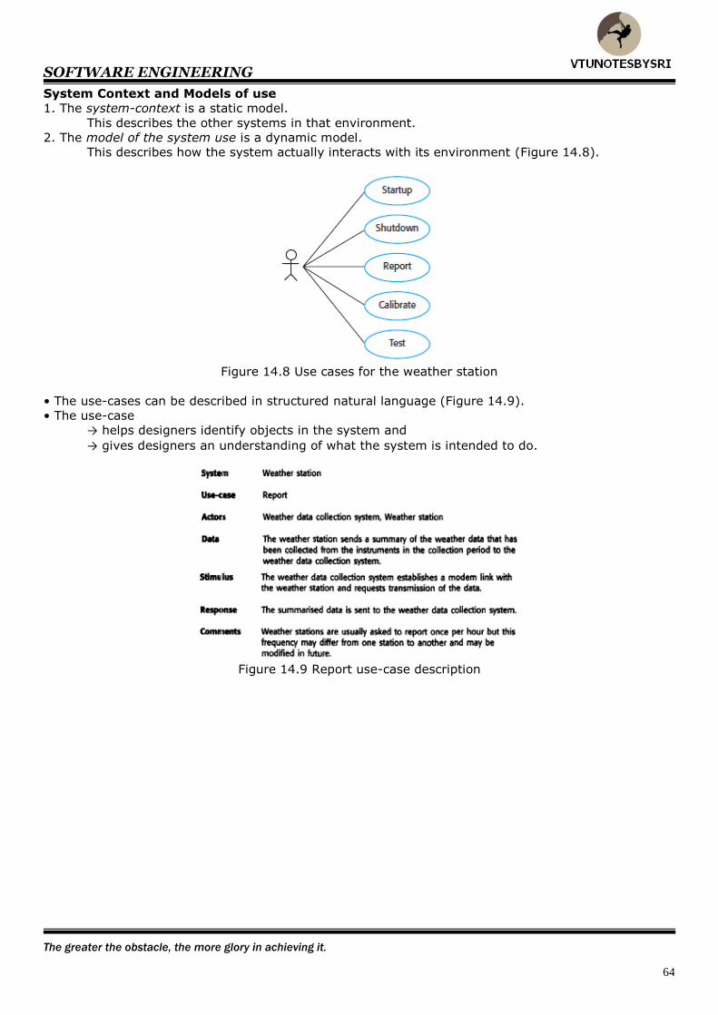
SOFTWARE ENGINEERING
The greater the obstacle, the more glory in achieving it.
64
System Context and Models of use
1. The system-context is a static model.
This describes the other systems in that environment.
2. The model of the system use is a dynamic model.
This describes how the system actually interacts with its environment (Figure 14.8).
Figure 14.8 Use cases for the weather station
• The use-cases can be described in structured natural language (Figure 14.9).
• The use-case
→ helps designers identify objects in the system and
→ gives designers an understanding of what the system is intended to do.
Figure 14.9 Report use-case description
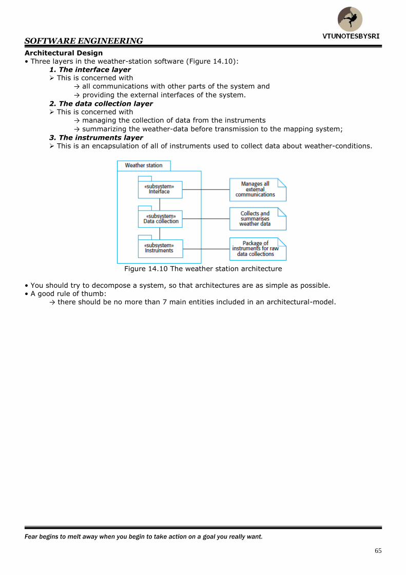
SOFTWARE ENGINEERING
Fear begins to melt away when you begin to take action on a goal you really want.
65
Architectural Design
• Three layers in the weather-station software (Figure 14.10):
1. The interface layer This is concerned with
→ all communications with other parts of the system and
→ providing the external interfaces of the system.
2. The data collection layer This is concerned with
→ managing the collection of data from the instruments
→ summarizing the weather-data before transmission to the mapping system;
3. The instruments layer
This is an encapsulation of all of instruments used to collect data about weather-conditions.
Figure 14.10 The weather station architecture
• You should try to decompose a system, so that architectures are as simple as possible.
• A good rule of thumb:
→ there should be no more than 7 main entities included in an architectural-model.

SOFTWARE ENGINEERING
Success is having your best day everyday.
66
Object Identification
• This process is actually concerned with identifying object-classes (Figure 14.11).
• Guidelines to identify object-classes:
1. Use a grammatical analysis of a natural language description of a system.
Objects and attributes are nouns.
Operations or services are verbs.
2. Use tangible entities For example,
→ application domain such as aircraft
→ roles such as manager and
→ events such as request.
3. Use a behavioural approach The designer first understands the overall behaviour of the system.
The various behaviours are assigned to different parts of the system.
An understanding is derived of who initiates and participates in the behaviours.
4. Use a scenario-based analysis Various scenarios of system-use are identified and analyzed.
As each scenario is analyzed, the team must identify the required objects, attributes and
operations.
Figure 14.11: Identification of the weather station objects
Design Models
• These show
→ objects (or classes) in a system and
→ relationships between the objects(or classes)
• They are the bridge between
→ requirements for the system and
→ system-implementation.
• Two types of design-models:
1. Static Models These describe the static-structure of the system using object-classes and their relationships.
Important relationships documented are:
→ generalization relationships
→ uses/used-by relationships and
→ composition relationships.
2. Dynamic Models These
→ describe the dynamic-structure of the system and
→ show the interactions between the objects (not the classes).
Important interactions documented are:
→ sequence of service-requests made by objects and
→ way in which the state of the system is related to the object interactions.
Two popular models are 1) Sequence models & 2) State machine models

SOFTWARE ENGINEERING
The price of excellence is discipline. The cost of mediocrity is disappointment.
67
Sequence Models
• These are dynamic-models.
• These show the sequence of object-interactions.
• How to draw sequence-models (Figure 14.13):
1. The objects are arranged horizontally with a vertical line linked to each object.
2. Time is represented vertically.
3. Labeled arrows linking the vertical lines represent interactions between objects.
These are not data flows but represent messages or events.
4. The thin rectangle on the object-lifeline represents the time when the object is the
controlling-object in the system.
An object takes over control at the top of this rectangle and relinquishes
control to another object at the bottom of the rectangle.
Figure 14.13 Sequence of operations-data collection
State Machine Models
• These are dynamic models (Figure 14.14).
• These show how individual objects change their state in response to events.
• These are represented in the UML using statechart diagrams.
Figure 14.14 State diagram for WeatherStation
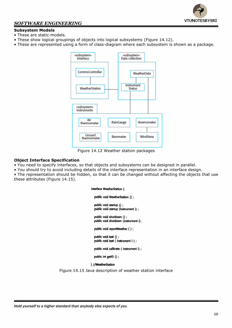
SOFTWARE ENGINEERING
Hold yourself to a higher standard than anybody else expects of you.
68
Subsystem Models
• These are static-models.
• These show logical groupings of objects into logical subsystems (Figure 14.12).
• These are represented using a form of class-diagram where each subsystem is shown as a package.
Figure 14.12 Weather station packages
Object Interface Specification
• You need to specify interfaces, so that objects and subsystems can be designed in parallel.
• You should try to avoid including details of the interface representation in an interface design.
• The representation should be hidden, so that it can be changed without affecting the objects that use
these attributes (Figure 14.15).
Figure 14.15 Java description of weather station interface
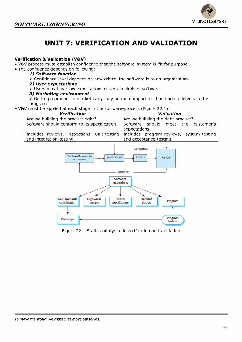
SOFTWARE ENGINEERING
To move the world, we must first move ourselves.
69
UNIT 7: VERIFICATION AND VALIDATION
Verification & Validation (V&V)
• V&V process must establish confidence that the software-system is 'fit for purpose'.
• The confidence depends on following:
1) Software function Confidence-level depends on how critical the software is to an organisation.
2) User expectations Users may have low expectations of certain kinds of software.
3) Marketing environment
Getting a product to market early may be more important than finding defects in the
program.
• V&V must be applied at each stage in the software-process (Figure 22.1).
Verification Validation
Are we building the product right? Are we building the right product?
Software should conform to its specification. Software should meet the customer’s
expectations.
Includes reviews, inspections, unit-testing
and integration-testing.
Includes program-reviews, system-testing
and acceptance-testing.
Figure 22.1 Static and dynamic verification and validation
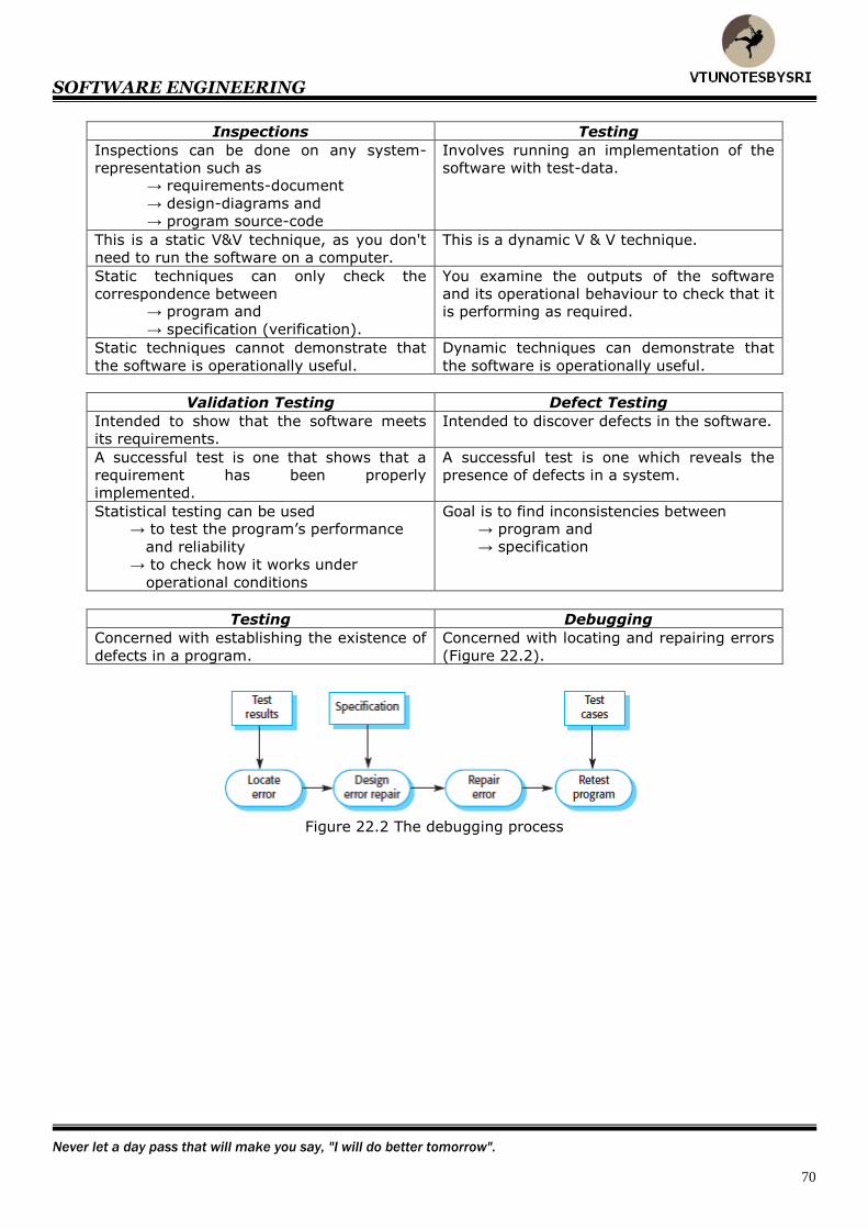
SOFTWARE ENGINEERING
Never let a day pass that will make you say, "I will do better tomorrow".
70
Inspections Testing
Inspections can be done on any system-
representation such as → requirements-document
→ design-diagrams and
→ program source-code
Involves running an implementation of the
software with test-data.
This is a static V&V technique, as you don't
need to run the software on a computer.
This is a dynamic V & V technique.
Static techniques can only check the
correspondence between → program and
→ specification (verification).
You examine the outputs of the software
and its operational behaviour to check that it
is performing as required.
Static techniques cannot demonstrate that
the software is operationally useful.
Dynamic techniques can demonstrate that
the software is operationally useful.
Validation Testing Defect Testing
Intended to show that the software meets
its requirements.
Intended to discover defects in the software.
A successful test is one that shows that a
requirement has been properly
implemented.
A successful test is one which reveals the
presence of defects in a system.
Statistical testing can be used → to test the program’s performance
and reliability
→ to check how it works under
operational conditions
Goal is to find inconsistencies between → program and
→ specification
Testing Debugging
Concerned with establishing the existence of
defects in a program.
Concerned with locating and repairing errors
(Figure 22.2).
Figure 22.2 The debugging process
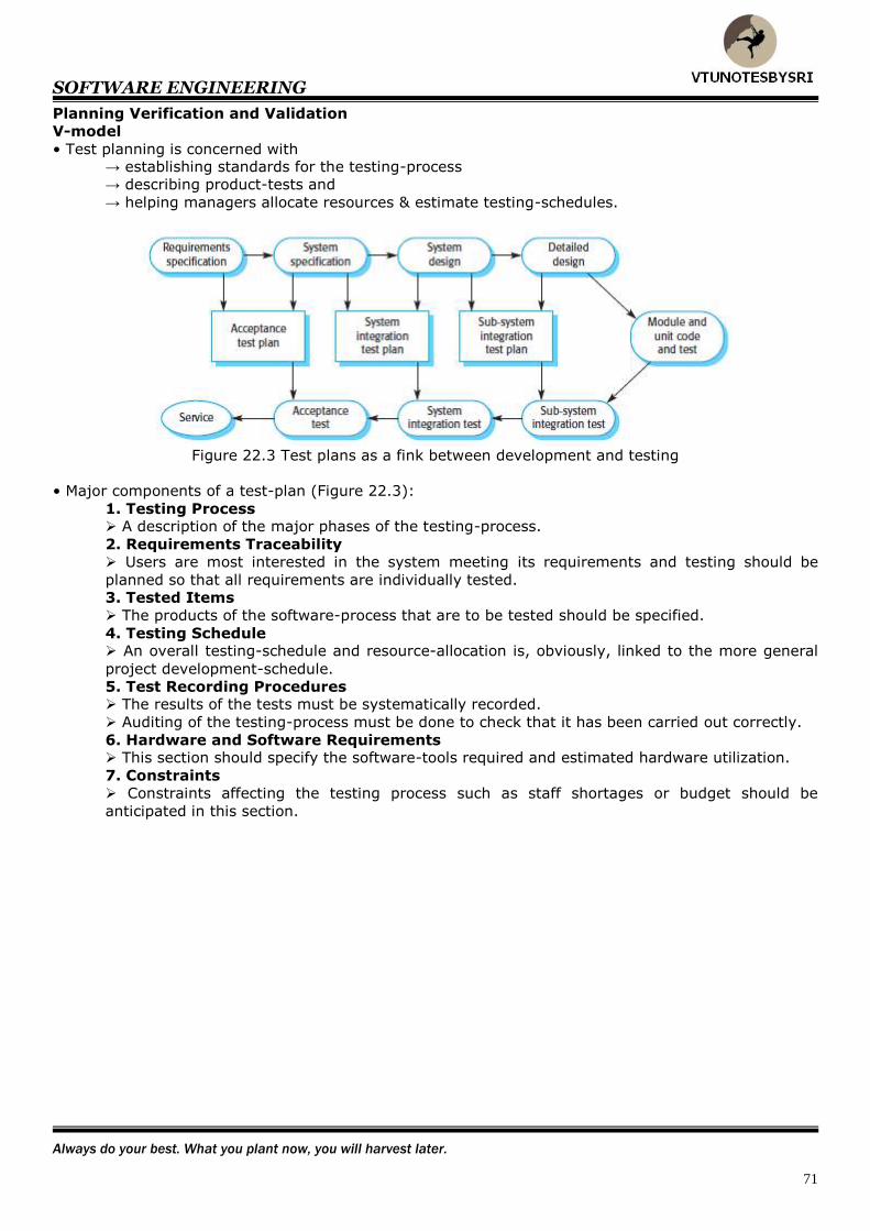
SOFTWARE ENGINEERING
Always do your best. What you plant now, you will harvest later.
71
Planning Verification and Validation
V-model
• Test planning is concerned with → establishing standards for the testing-process
→ describing product-tests and
→ helping managers allocate resources & estimate testing-schedules.
Figure 22.3 Test plans as a fink between development and testing
• Major components of a test-plan (Figure 22.3):
1. Testing Process A description of the major phases of the testing-process.
2. Requirements Traceability
Users are most interested in the system meeting its requirements and testing should be
planned so that all requirements are individually tested.
3. Tested Items
The products of the software-process that are to be tested should be specified.
4. Testing Schedule An overall testing-schedule and resource-allocation is, obviously, linked to the more general
project development-schedule.
5. Test Recording Procedures The results of the tests must be systematically recorded.
Auditing of the testing-process must be done to check that it has been carried out correctly.
6. Hardware and Software Requirements This section should specify the software-tools required and estimated hardware utilization.
7. Constraints
Constraints affecting the testing process such as staff shortages or budget should be
anticipated in this section.

SOFTWARE ENGINEERING
A dream is just a dream. A goal is a dream with a plan and a deadline
72
Inspection
• This is a static V&V technique (as you don't need to run the software on a computer).
• This involves reviewing the system to find → errors and
→ anomalies (or inconsistencies).
• This can be done on any system-representation such as → requirements-document
→ design-diagrams and
→ program source-code.
• This can only check the correspondence between
→ program and
→ specification.
• This cannot demonstrate that the software is operationally useful.
• Advantages of inspection over testing:
1. Many different defects may be discovered in a single inspection. In testing, one defect, may mask another (interaction between errors) so several executions
are required.
2. Incomplete versions of a system can be inspected without additional costs. If a program is incomplete, then you need to develop specialized test harnesses to test the
parts that are available. This obviously adds to the development-costs.
3. An inspection can consider broader quality-attributes such as → compliance with standards
→ inappropriate algorithms and
→ poor programming style.
Program Inspection Process
• Program-inspections are reviews whose objective is defect-detection in a program.
• Defects may be
→ logical errors
→ anomalies that indicate an erroneous condition or
→ non-compliance with organisational-standards.
• The program-inspection is carried out by a team of at least 4 people.
Inspection Roles
1. Author or Owner
He is responsible for
→ producing the program or document and
→ fixing defects discovered during the inspection process.
2. Inspector He is responsible for
→ finding errors (or inconsistencies) in programs (or documents) and
→ identifying broader issues that are outside the scope of the inspection-team.
3. Reader
He is responsible for
→ presenting the code (or document) at an inspection meeting.
4. Scribe He is responsible for
→ recording the results of the inspection meeting.
5. Chairman or Moderator He is responsible for
→ managing the process
→ facilitating the inspection and
→ reporting process-results to the chief moderator.
6. Chief Moderator He is responsible for
→ inspection process improvements
→ checklist updating and
→ standards development.

SOFTWARE ENGINEERING
The difference between the impossible and the possible lies in a man's determination.
73
Inspection Checklists
• Inspection-team must have a precise specification of the code to be inspected (Figure 22.6 & 22.7).
• Inspection-team must be familiar with the organisational standards.
• An up-to-date, compatible version of the code must be distributed to the inspection-team.
Figure 22.6 The inspection process
Figure 22.7 Inspection checks
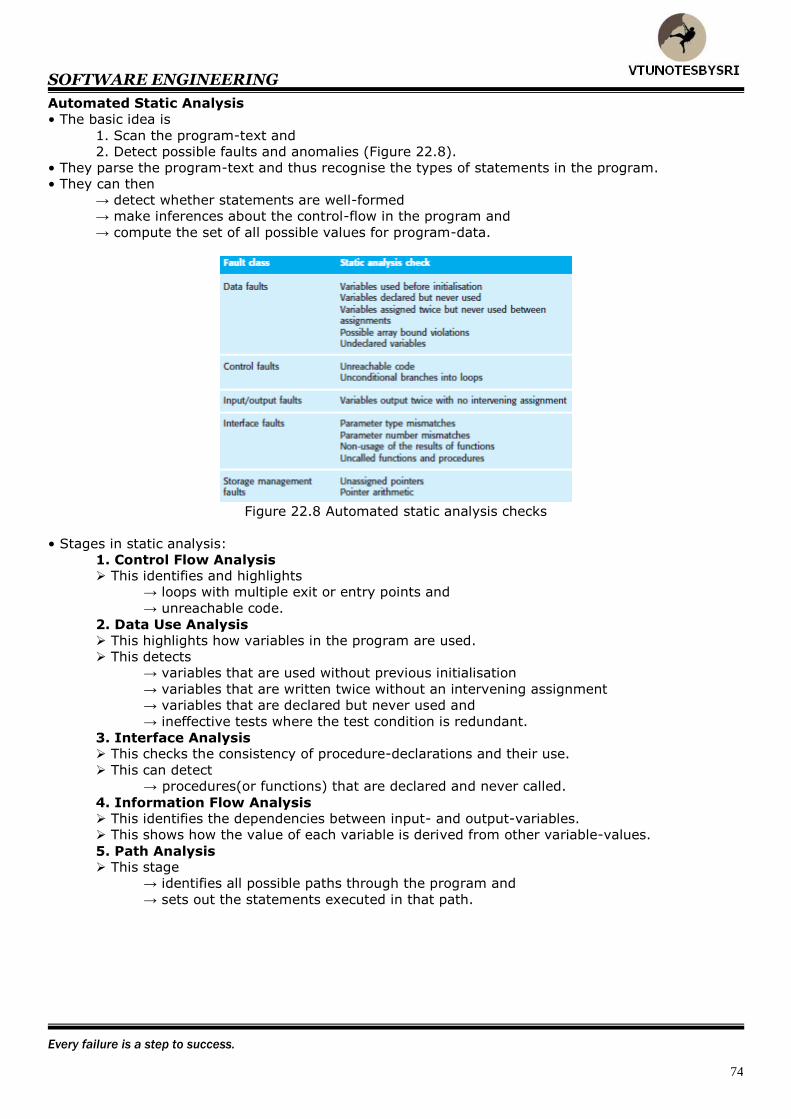
SOFTWARE ENGINEERING
Every failure is a step to success.
74
Automated Static Analysis
• The basic idea is
1. Scan the program-text and
2. Detect possible faults and anomalies (Figure 22.8).
• They parse the program-text and thus recognise the types of statements in the program.
• They can then
→ detect whether statements are well-formed
→ make inferences about the control-flow in the program and
→ compute the set of all possible values for program-data.
Figure 22.8 Automated static analysis checks
• Stages in static analysis:
1. Control Flow Analysis This identifies and highlights
→ loops with multiple exit or entry points and
→ unreachable code.
2. Data Use Analysis
This highlights how variables in the program are used.
This detects
→ variables that are used without previous initialisation
→ variables that are written twice without an intervening assignment
→ variables that are declared but never used and
→ ineffective tests where the test condition is redundant.
3. Interface Analysis This checks the consistency of procedure-declarations and their use.
This can detect
→ procedures(or functions) that are declared and never called.
4. Information Flow Analysis This identifies the dependencies between input- and output-variables.
This shows how the value of each variable is derived from other variable-values.
5. Path Analysis This stage
→ identifies all possible paths through the program and
→ sets out the statements executed in that path.

SOFTWARE ENGINEERING
If what you did yesterday seems big, you haven't done anything today.
75
Verification and Formal Methods
• Formal methods of software-development are based on mathematical-representations of the software
(usually as a formal specification).
• The formal methods are mainly concerned → with a mathematical-analysis of the specification or
→ with transforming the specification to a semantically equivalent representation.
1. Arguments for Formal Methods
• Formal-specification forces a detailed-analysis of the specification.
• May reveal potential inconsistencies that might not otherwise be discovered until the system is
operational
2. Arguments against Formal Methods
• These can only be used by specially trained-staff and cannot be understood by domain-experts
• Extremely expensive-process because → as the system-size increases, the costs of formal-verification increase.
• Formal-specification (and proof) do not guarantee that the software will be reliable in practical use.
The reasons for this are:
1. The specification may not reflect the real requirements of system users.
2. The proof may contain errors.
3. The proof may assume a usage-pattern which is incorrect.

SOFTWARE ENGINEERING
Opportunity often comes disguised in the form of misfortune or temporary defeat.
76
Cleanroom Software Development
• Objective: to develop a zero-defect software.
Figure 22.10 The Cleanroom development process
• The software-development is based on 5 key strategies (Figure 22.10):
1. Formal Specification The software to be developed is formally specified.
A state-transition-model is used to express the specification.
The state-model shows system-responses to stimuli.
2. Incremental Development
The software is divided into increments that are developed and validated separately.
These increments are specified, with customer-input, at an early stage in the process.
3. Structured Programming
A limited number of constructs are used.
The aim is to systematically transform the specification to create the program-code.
4. Static Verification
The developed-software is statically verified using software-inspections.
There is no unit-testing process for code-components.
5. Statistical Testing of the System
The integrated-software is tested statistically to determine its reliability.
• Three teams in the system-development:
1. The Specification Team This team is responsible for developing and maintaining the system-specification.
This team produces
→ customer-oriented specifications (the user requirements definition) and
→ mathematical specifications for verification.
2. The Development Team This team has the responsibility of developing and verifying the software.
The software is not executed during the development process.
3. The Certification Team This team is responsible for developing a set of statistical tests to exercise the software after
it has been developed. These tests are based on the formal-specification.
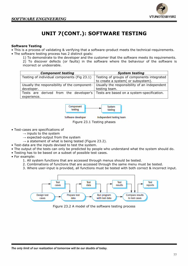
SOFTWARE ENGINEERING
The only limit of our realization of tomorrow will be our doubts of today.
77
UNIT 7(CONT.): SOFTWARE TESTING
Software Testing
• This is a process of validating & verifying that a software-product meets the technical-requirements.
• The software testing process has 2 distinct goals:
1) To demonstrate to the developer and the customer that the software meets its requirements.
2) To discover defects (or faults) in the software where the behaviour of the software is
incorrect or undesirable.
Component testing System testing
Testing of individual components (Fig 23.1) Testing of groups of components integrated
to create a system( or subsystem).
Usually the responsibility of the component-
developer.
Usually the responsibility of an independent
testing team.
Tests are derived from the developer’s
experience.
Tests are based on a system-specification.
Figure 23.1 Testing phases
• Test-cases are specifications of → inputs to the system
→ expected-output from the system
→ a statement of what is being tested (Figure 23.2).
• Test-data are the inputs devised to test the system.
• The output of the tests can only be predicted by people who understand what the system should do.
• Testing has to be based on a subset of possible test cases.
• For example:
1. All system functions that are accessed through menus should be tested.
2. Combinations of functions that are accessed through the same menu must be tested.
3. Where user-input is provided, all functions must be tested with both correct & incorrect input.
Figure 23.2 A model of the software testing process

SOFTWARE ENGINEERING
If your life is free of failures, you are not taking enough risks.
78
System Testing • The basic idea is
1. Integrate 2 or more components that implement system-features.
2. Then, test the integrated-system.
• Two phases of system-testing:
1. Integration Testing
2. Release Testing
Integration Testing
• The basic idea is
1. Build a system from its components and
2. Then, test the resultant-system for problems that arise from component-interactions.
• When a problem is discovered, the integration-team tries to → find the source of the problem and
→ identify the components that have to be debugged.
• The components that are integrated may be
1. Off-the-shelf components
2. Reusable components or
3. Newly developed components.
• Two types:
1) Top-down integration Develop the skeleton of the system and then populate it with components.
2) Bottom-up integration
Integrate infrastructure components then add functional-components.
• A major problem that arises during integration-testing is localizing errors.
Incremental Integration Testing
Figure 23.3 Incremental integration testing
• A, B, C and D are components and T1 to T5 are related sets of tests of the features incorporated in
the system (Figure 23.3).
• T1, T2 and T3 are first run on a system composed of component A and component B (the minimal
system). If these reveal defects, they are corrected.
• When planning integration, you have to decide the order of integration of components.
• A good rule of thumb: → integrate the components that implement the most frequently used functionality first.
• Rerunning an existing set of tests is called regression testing.
• Regression testing is clearly an expensive process and is impractical without some automated
support.
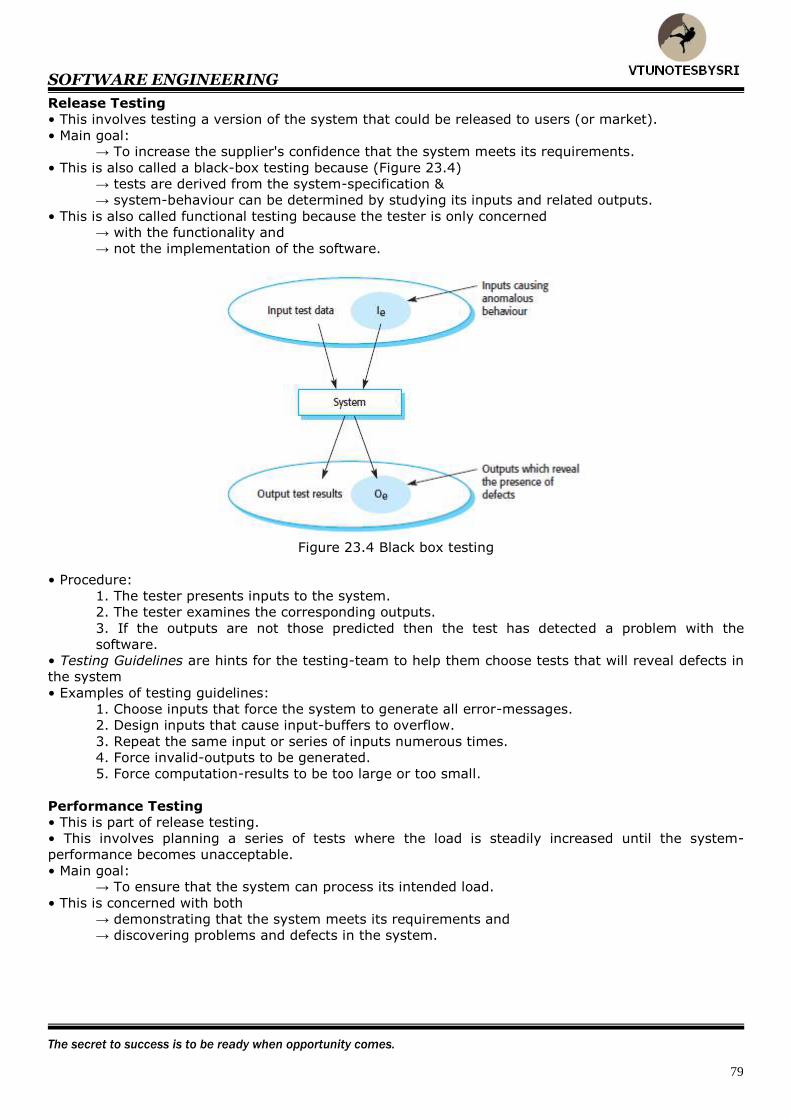
SOFTWARE ENGINEERING
The secret to success is to be ready when opportunity comes.
79
Release Testing
• This involves testing a version of the system that could be released to users (or market).
• Main goal: → To increase the supplier's confidence that the system meets its requirements.
• This is also called a black-box testing because (Figure 23.4)
→ tests are derived from the system-specification &
→ system-behaviour can be determined by studying its inputs and related outputs.
• This is also called functional testing because the tester is only concerned
→ with the functionality and
→ not the implementation of the software.
Figure 23.4 Black box testing
• Procedure:
1. The tester presents inputs to the system.
2. The tester examines the corresponding outputs.
3. If the outputs are not those predicted then the test has detected a problem with the
software.
• Testing Guidelines are hints for the testing-team to help them choose tests that will reveal defects in
the system
• Examples of testing guidelines:
1. Choose inputs that force the system to generate all error-messages.
2. Design inputs that cause input-buffers to overflow.
3. Repeat the same input or series of inputs numerous times.
4. Force invalid-outputs to be generated.
5. Force computation-results to be too large or too small.
Performance Testing
• This is part of release testing.
• This involves planning a series of tests where the load is steadily increased until the system-
performance becomes unacceptable.
• Main goal: → To ensure that the system can process its intended load.
• This is concerned with both
→ demonstrating that the system meets its requirements and
→ discovering problems and defects in the system.

SOFTWARE ENGINEERING
Your dreams come true when you act to turn them into realities.
80
Stress Testing
• This involves exercising the system beyond its maximum design-load.
• The testing has 2 functions:
1. Stressing the system often causes defects to come-to-light.
2. Stressing the failure behaviour of the system.
Systems should not fail catastrophically.
Stress testing checks for unacceptable loss of service or data.
• The testing is particularly important for distributed systems.
Component Testing
• This is also called as unit testing.
• This is the process of testing individual components in the system.
• Main goal:
→ To expose faults in the components.
• The developers of components are responsible for component-testing.
• Component may be:
1. Individual functions( or methods) within an object.
2. Object classes that have several attributes and methods.
3. Composite components made up of several different objects or functions.
• Object Class Testing should include:
1. Testing of all operations associated with the object.
2. Setting and interrogation of all attributes associated with the object.
3. Exercising the object in all possible states.
• Inheritance makes it more difficult to design object tests, as the information to be tested is not
localized.
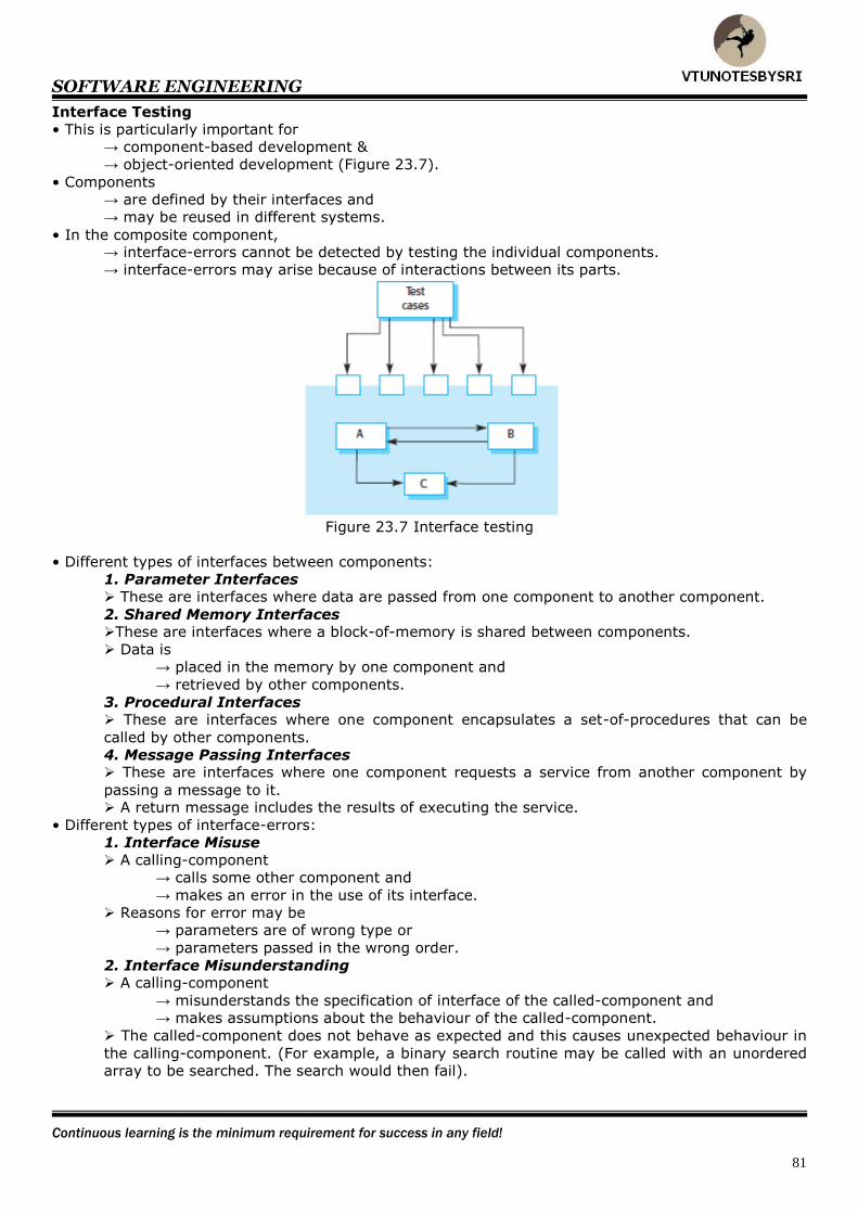
SOFTWARE ENGINEERING
Continuous learning is the minimum requirement for success in any field!
81
Interface Testing
• This is particularly important for
→ component-based development &
→ object-oriented development (Figure 23.7).
• Components
→ are defined by their interfaces and
→ may be reused in different systems.
• In the composite component, → interface-errors cannot be detected by testing the individual components.
→ interface-errors may arise because of interactions between its parts.
Figure 23.7 Interface testing
• Different types of interfaces between components:
1. Parameter Interfaces
These are interfaces where data are passed from one component to another component.
2. Shared Memory Interfaces These are interfaces where a block-of-memory is shared between components.
Data is
→ placed in the memory by one component and
→ retrieved by other components.
3. Procedural Interfaces These are interfaces where one component encapsulates a set-of-procedures that can be
called by other components.
4. Message Passing Interfaces These are interfaces where one component requests a service from another component by
passing a message to it. A return message includes the results of executing the service.
• Different types of interface-errors:
1. Interface Misuse
A calling-component
→ calls some other component and
→ makes an error in the use of its interface.
Reasons for error may be
→ parameters are of wrong type or
→ parameters passed in the wrong order.
2. Interface Misunderstanding A calling-component
→ misunderstands the specification of interface of the called-component and
→ makes assumptions about the behaviour of the called-component.
The called-component does not behave as expected and this causes unexpected behaviour in
the calling-component. (For example, a binary search routine may be called with an unordered
array to be searched. The search would then fail).

SOFTWARE ENGINEERING
The more goals you set, the more goals you get.
82
3. Timing Errors These occur in real-time systems that use
1) Shared memory or
2) Message-passing interface. The producer of data and the consumer of data may operate at different speeds.
The consumer can access out-of-date information because the producer of the information
has not updated the shared interface information.
• Guidelines for interface testing:
1. Examine the code to be tested.
Explicitly list each call to an external component.
2. Where pointers are passed across an interface, always test the interface with null pointer
parameters.
3. Where a component is called through a procedural interface, design tests that should cause
the component to fail.
4. Use stress testing in message-passing system.
5. Where several components interact through shared memory, design tests that vary the order
in which these components are activated.

SOFTWARE ENGINEERING
You can get everything you want if you help enough others get what they want.
83
Test Case Design • This involves designing the test-cases (inputs and outputs) used to test the system.
• Goal: to create a set of test-cases that are effective in validation and defect testing.
• Three design approaches:
1. Requirements-based testing
2. Partition testing and
3. Structural testing.
• You use knowledge of the program's structure to design tests that exercise all parts of the program.
• Essentially, when testing a program, you should try to execute each statement at least once.
Requirements based Testing
• This is a validation testing technique.
• You consider each requirement and derive a set of tests cases for that requirement.
• This is used at the system-testing stage, as system requirements are usually implemented by several
components.

SOFTWARE ENGINEERING
If you want your dreams to come true then WAKE UP!
84
Partition Testing
• The input-data and output-results of a program usually fall into a number of different classes that
have common features such as → positive numbers &
→ negative numbers.
• Programs normally behave in a comparable way for all members of a class.
• Because of this equivalent behaviour, these classes are also called equivalence partitions.
• The basic idea is
1. Identify input & output partitions.
2. Then, design test-cases accordingly (Figure 23.8).
• This ensures that the system → executes inputs from all partitions and
→ generates outputs in all partitions.
• This can be used to design test-cases for both systems and components.
Figure 23.8: Equivalence partitioning
• If a set of partitions are identified, then choose test-cases from each of these partitions.
• A thumb rule for test-case selection:
1. Choose test-cases on the boundaries of the partitions and
2. Choose test-cases close to the mid-point of the partition (Figure 23.9).
Figure 23.9 Equivalence partitions
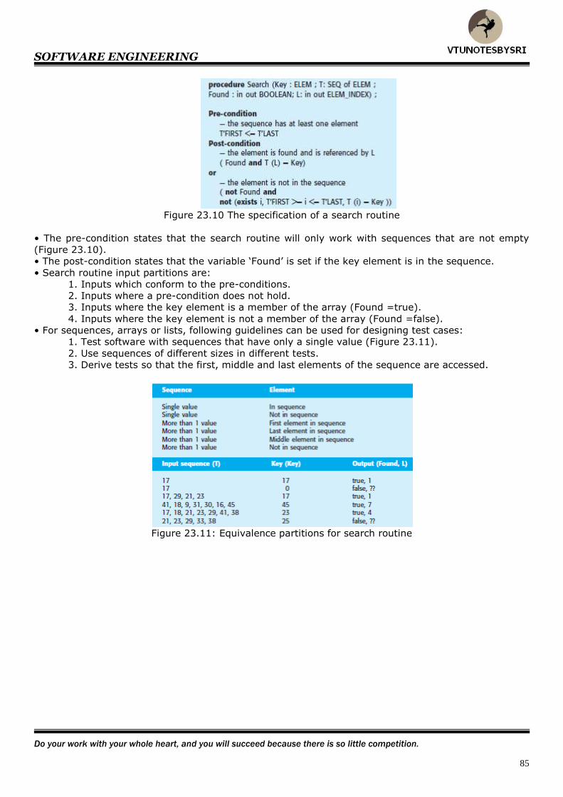
SOFTWARE ENGINEERING
Do your work with your whole heart, and you will succeed because there is so little competition.
85
Figure 23.10 The specification of a search routine
• The pre-condition states that the search routine will only work with sequences that are not empty
(Figure 23.10).
• The post-condition states that the variable ‘Found’ is set if the key element is in the sequence.
• Search routine input partitions are:
1. Inputs which conform to the pre-conditions.
2. Inputs where a pre-condition does not hold.
3. Inputs where the key element is a member of the array (Found =true).
4. Inputs where the key element is not a member of the array (Found =false).
• For sequences, arrays or lists, following guidelines can be used for designing test cases:
1. Test software with sequences that have only a single value (Figure 23.11).
2. Use sequences of different sizes in different tests.
3. Derive tests so that the first, middle and last elements of the sequence are accessed.
Figure 23.11: Equivalence partitions for search routine
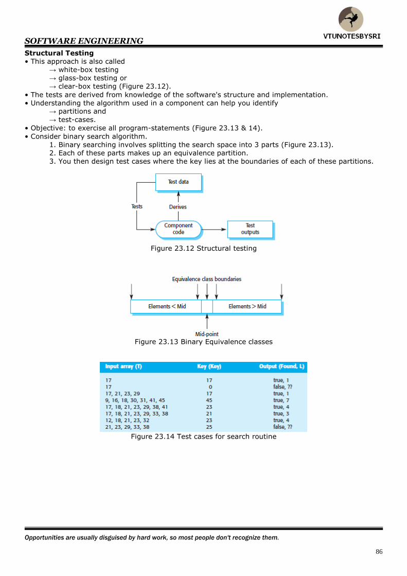
SOFTWARE ENGINEERING
Opportunities are usually disguised by hard work, so most people don't recognize them.
86
Structural Testing
• This approach is also called
→ white-box testing
→ glass-box testing or
→ clear-box testing (Figure 23.12).
• The tests are derived from knowledge of the software's structure and implementation.
• Understanding the algorithm used in a component can help you identify → partitions and
→ test-cases.
• Objective: to exercise all program-statements (Figure 23.13 & 14).
• Consider binary search algorithm.
1. Binary searching involves splitting the search space into 3 parts (Figure 23.13).
2. Each of these parts makes up an equivalence partition.
3. You then design test cases where the key lies at the boundaries of each of these partitions.
Figure 23.12 Structural testing
Figure 23.13 Binary Equivalence classes
Figure 23.14 Test cases for search routine
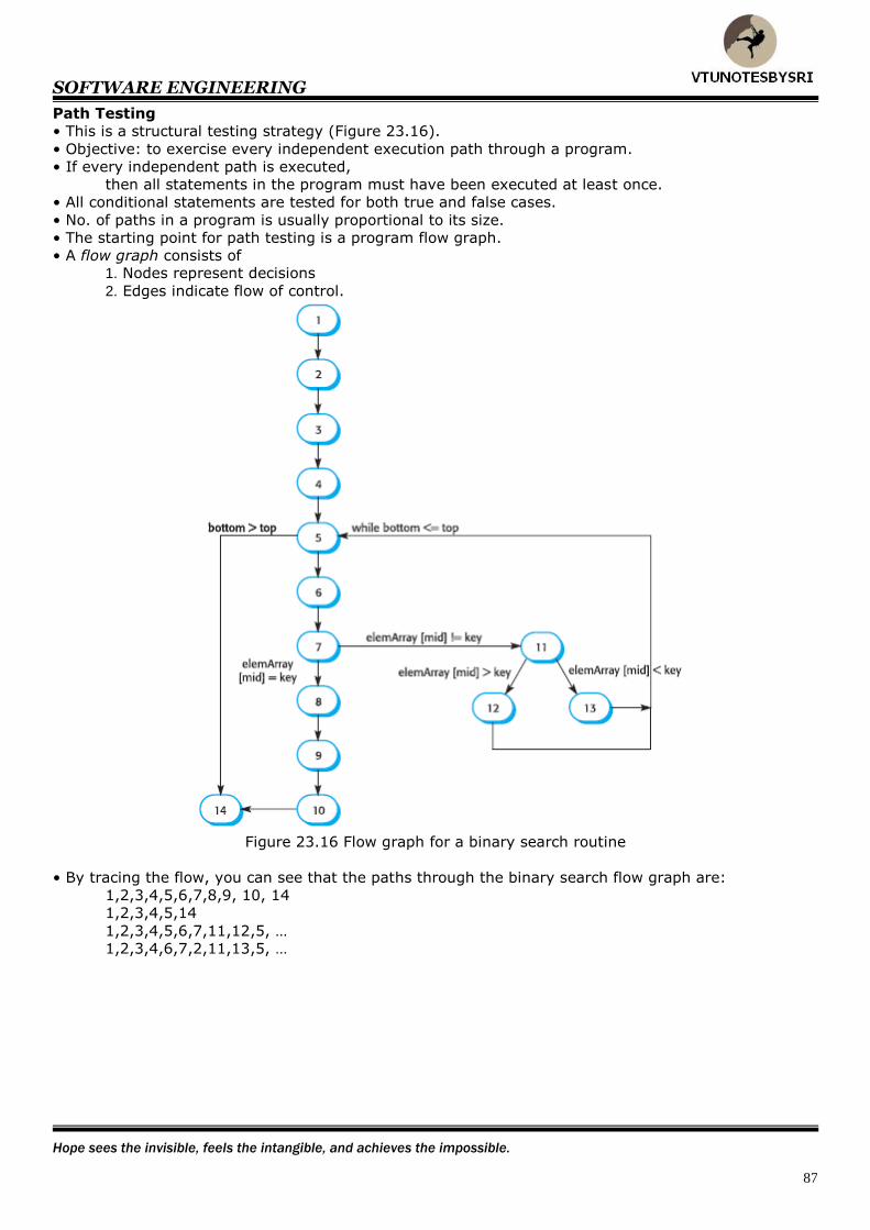
SOFTWARE ENGINEERING
Hope sees the invisible, feels the intangible, and achieves the impossible.
87
Path Testing
• This is a structural testing strategy (Figure 23.16).
• Objective: to exercise every independent execution path through a program.
• If every independent path is executed,
then all statements in the program must have been executed at least once.
• All conditional statements are tested for both true and false cases.
• No. of paths in a program is usually proportional to its size.
• The starting point for path testing is a program flow graph.
• A flow graph consists of 1. Nodes represent decisions
2. Edges indicate flow of control.
Figure 23.16 Flow graph for a binary search routine
• By tracing the flow, you can see that the paths through the binary search flow graph are:
1,2,3,4,5,6,7,8,9, 10, 14
1,2,3,4,5,14
1,2,3,4,5,6,7,11,12,5, …
1,2,3,4,6,7,2,11,13,5, …
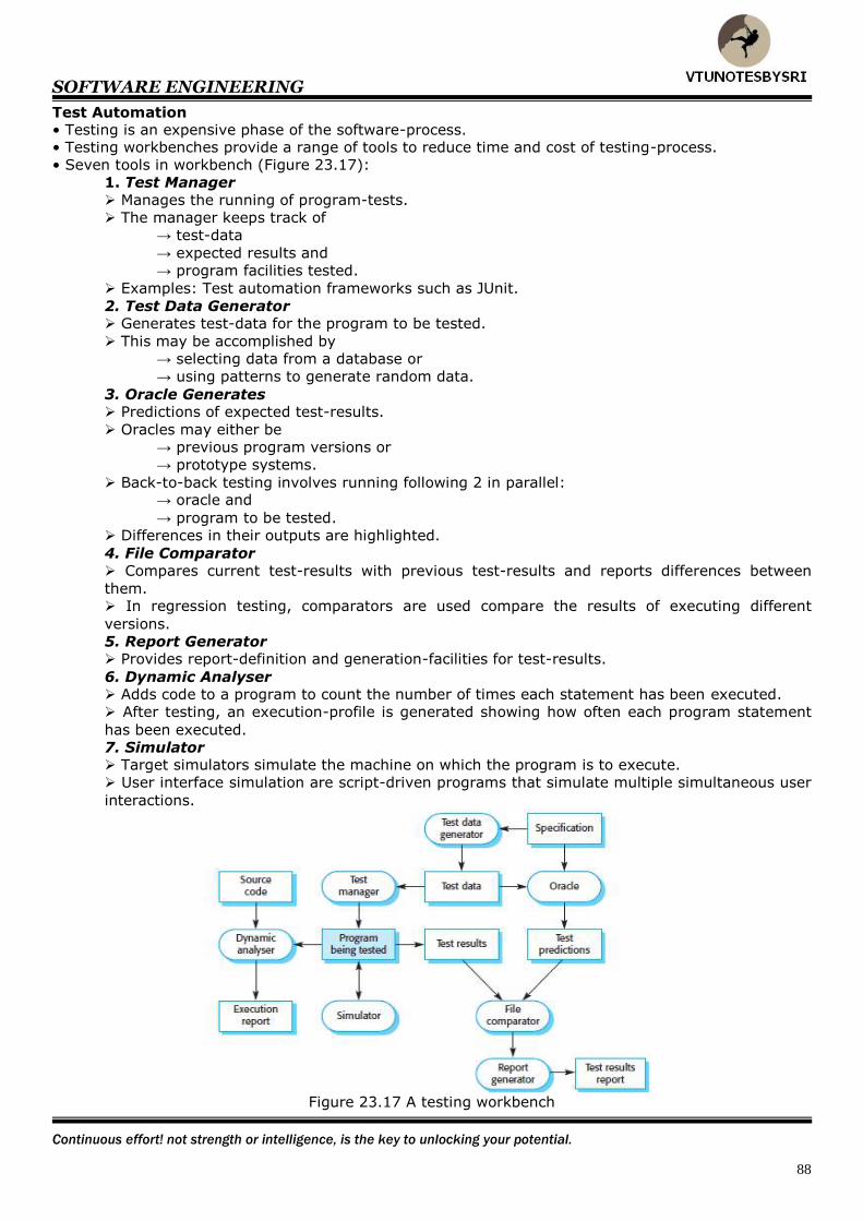
SOFTWARE ENGINEERING
Continuous effort! not strength or intelligence, is the key to unlocking your potential.
88
Test Automation • Testing is an expensive phase of the software-process. • Testing workbenches provide a range of tools to reduce time and cost of testing-process.
• Seven tools in workbench (Figure 23.17):
1. Test Manager
Manages the running of program-tests.
The manager keeps track of
→ test-data
→ expected results and
→ program facilities tested.
Examples: Test automation frameworks such as JUnit.
2. Test Data Generator Generates test-data for the program to be tested.
This may be accomplished by
→ selecting data from a database or
→ using patterns to generate random data.
3. Oracle Generates Predictions of expected test-results.
Oracles may either be
→ previous program versions or
→ prototype systems.
Back-to-back testing involves running following 2 in parallel: → oracle and
→ program to be tested.
Differences in their outputs are highlighted.
4. File Comparator
Compares current test-results with previous test-results and reports differences between
them. In regression testing, comparators are used compare the results of executing different
versions.
5. Report Generator Provides report-definition and generation-facilities for test-results.
6. Dynamic Analyser Adds code to a program to count the number of times each statement has been executed.
After testing, an execution-profile is generated showing how often each program statement
has been executed.
7. Simulator Target simulators simulate the machine on which the program is to execute.
User interface simulation are script-driven programs that simulate multiple simultaneous user
interactions.
Figure 23.17 A testing workbench


![VTU Cse III Electronic Circuits [10cs32]](https://img.pdfslide.net/doc/110x75/5695d1bf1a28ab9b0297c28b/vtu-cse-iii-electronic-circuits-10cs32.jpg)