Embed Size (px)
Citation preview

CVLE 519
Concrete Technology
Dr. Adel El Kordi
Professor
Civil and Environmental Engineering
Department
Faculty of Engineering
Structural Assessment
• Need to understand “in-situ” conditions
1. Actual geometry – d, b, l
2. Geometry variations
3. Material strength – f’c and fy
4. Deterioration / loss of strength
Structural Assessment
1. Member sizes
2. Location and spacing of embedded items
a. Mild reinforcing steel, post-tensioning, conduit
b. Masonry ties and hardware
3. Corrosion damage assessment
4. Concrete properties
5. Reinforcing steel properties
Typical Conditions to Verify
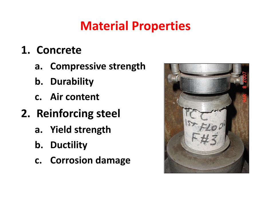
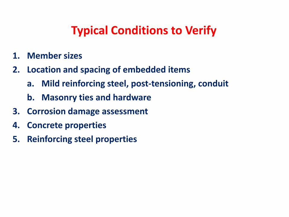
1. Concrete
a. Compressive strength
b. Durability
c. Air content
2. Reinforcing steel
a. Yield strength
b. Ductility
c. Corrosion damage
Material Properties
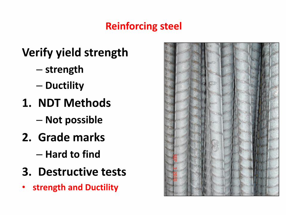
Verify yield strength
– strength
– Ductility
1. NDT Methods
– Not possible
2. Grade marks
– Hard to find
3. Destructive tests• strength and Ductility
Reinforcing steel
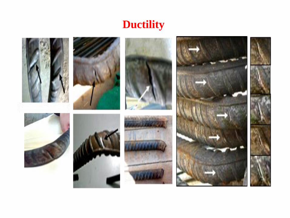
Ductility
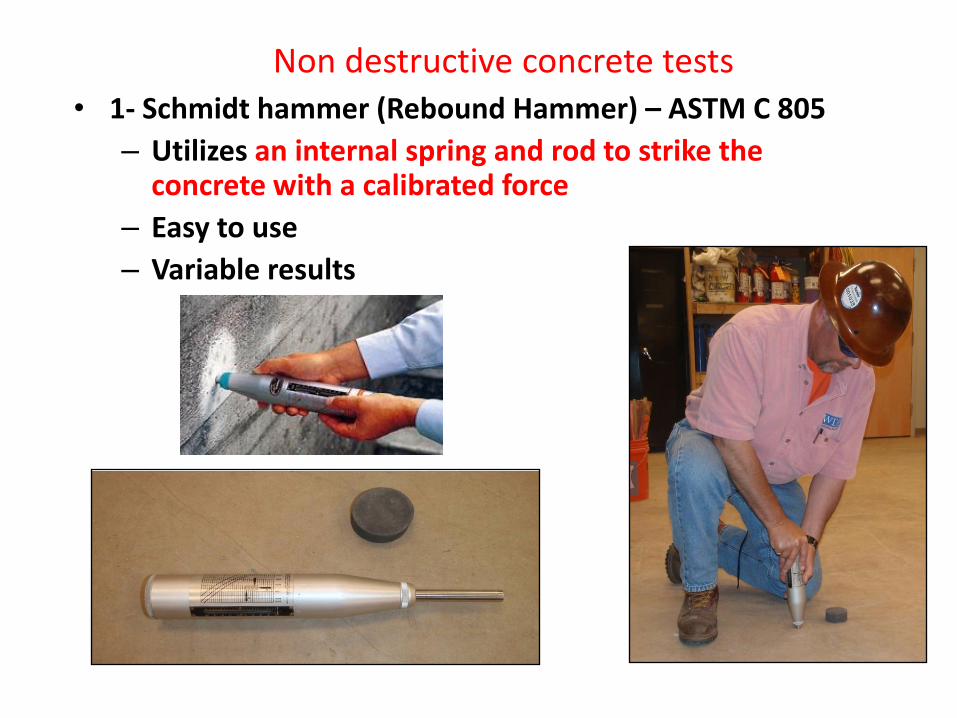
• 1- Schmidt hammer (Rebound Hammer) – ASTM C 805
– Utilizes an internal spring and rod to strike the concrete with a calibrated force
– Easy to use
– Variable results
Non destructive concrete tests
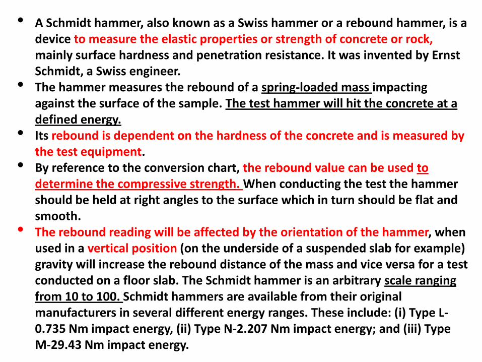
• A Schmidt hammer, also known as a Swiss hammer or a rebound hammer, is a device to measure the elastic properties or strength of concrete or rock, mainly surface hardness and penetration resistance. It was invented by Ernst Schmidt, a Swiss engineer.
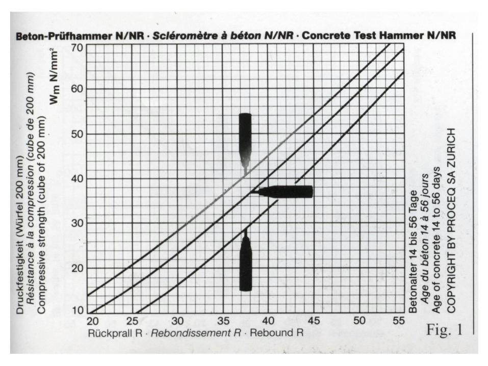
• The hammer measures the rebound of a spring-loaded mass impacting against the surface of the sample. The test hammer will hit the concrete at a defined energy.
• Its rebound is dependent on the hardness of the concrete and is measured by the test equipment.
• By reference to the conversion chart, the rebound value can be used to determine the compressive strength. When conducting the test the hammer should be held at right angles to the surface which in turn should be flat and smooth.
• The rebound reading will be affected by the orientation of the hammer, when used in a vertical position (on the underside of a suspended slab for example) gravity will increase the rebound distance of the mass and vice versa for a test conducted on a floor slab. The Schmidt hammer is an arbitrary scale ranging from 10 to 100. Schmidt hammers are available from their original manufacturers in several different energy ranges. These include: (i) Type L-0.735 Nm impact energy, (ii) Type N-2.207 Nm impact energy; and (iii) Type M-29.43 Nm impact energy.

The test is also sensitive to other factors:1- Local variation in the sample. To minimize this take a selection of readings and take an average value (12 readings ).2- Water content of the sample, a saturated material will give different results from a dry one.
Prior to testing, the Schmidt hammer should be calibrated using a calibration test anvil supplied by the manufacturer for that purpose. 12 readings should be taken, dropping the highest and lowest, and then take the average of the ten remaining. Using this method of testing is classed as indirect as it does not give a direct measurement of the strength of the material. It simply gives an indication based on surface properties, it is only suitable for making comparisons between samples.
This test method for testing concrete is governed by ASTM C805. ASTM D5873 describes the procedure for testing of rock.
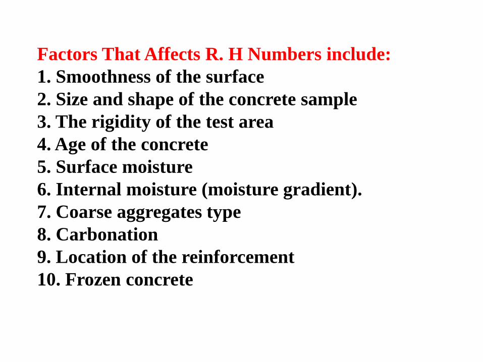
Factors That Affects R. H Numbers include:
1. Smoothness of the surface
2. Size and shape of the concrete sample
3. The rigidity of the test area
4. Age of the concrete
5. Surface moisture
6. Internal moisture (moisture gradient).
7. Coarse aggregates type
8. Carbonation
9. Location of the reinforcement
10. Frozen concrete
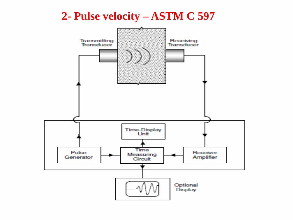
2- Pulse velocity – ASTM C 597
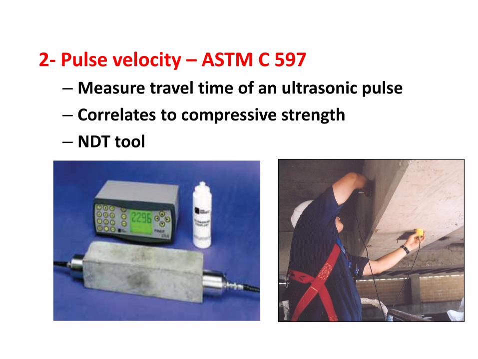
2- Pulse velocity – ASTM C 597
– Measure travel time of an ultrasonic pulse
– Correlates to compressive strength
– NDT tool
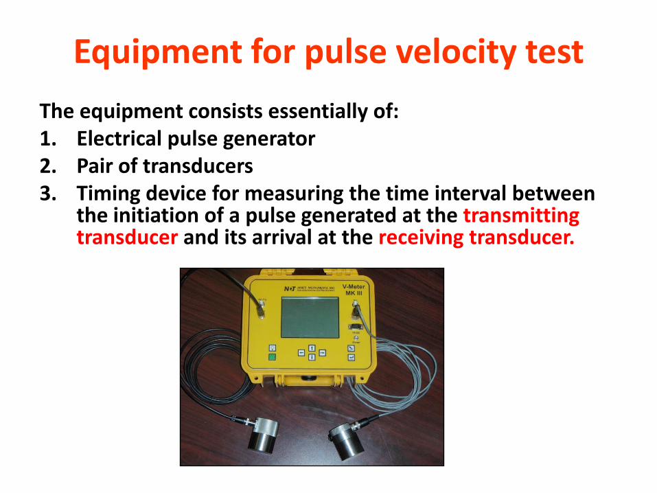
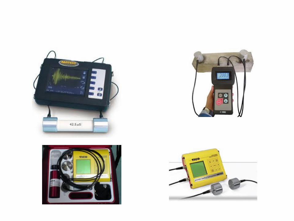
Equipment for pulse velocity test
The equipment consists essentially of:1. Electrical pulse generator2. Pair of transducers3. Timing device for measuring the time interval between
the initiation of a pulse generated at the transmitting transducer and its arrival at the receiving transducer.
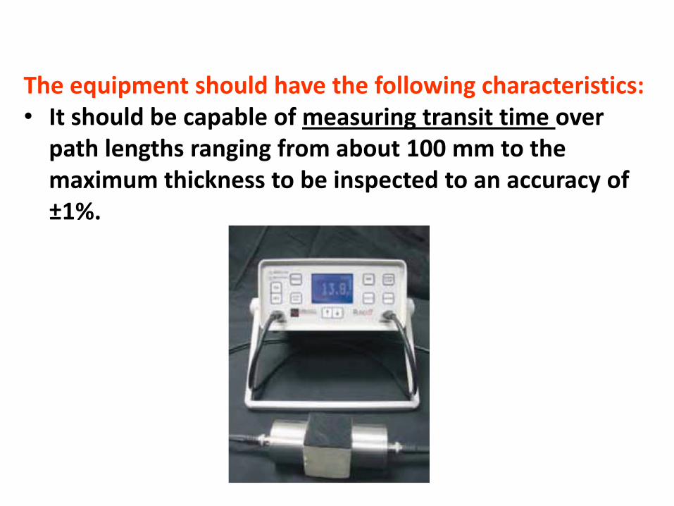
The equipment should have the following characteristics:• It should be capable of measuring transit time over
path lengths ranging from about 100 mm to the maximum thickness to be inspected to an accuracy of ±1%.
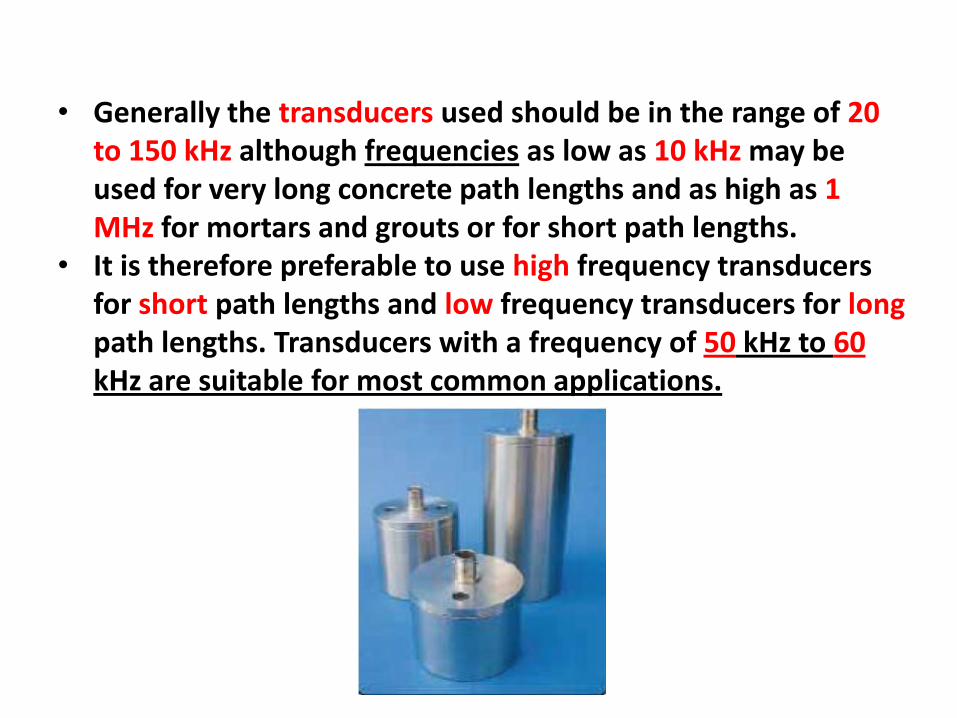
• Generally the transducers used should be in the range of 20 to 150 kHz although frequencies as low as 10 kHz may be used for very long concrete path lengths and as high as 1 MHz for mortars and grouts or for short path lengths.
• It is therefore preferable to use high frequency transducers for short path lengths and low frequency transducers for longpath lengths. Transducers with a frequency of 50 kHz to 60kHz are suitable for most common applications.
• Longitudinal pulse velocity (in km/s or m/s) is given by:
v = L /T
where
• v is the longitudinal pulse velocity,
• L is the path length,
• T is the time taken by the pulse to traverse that length.
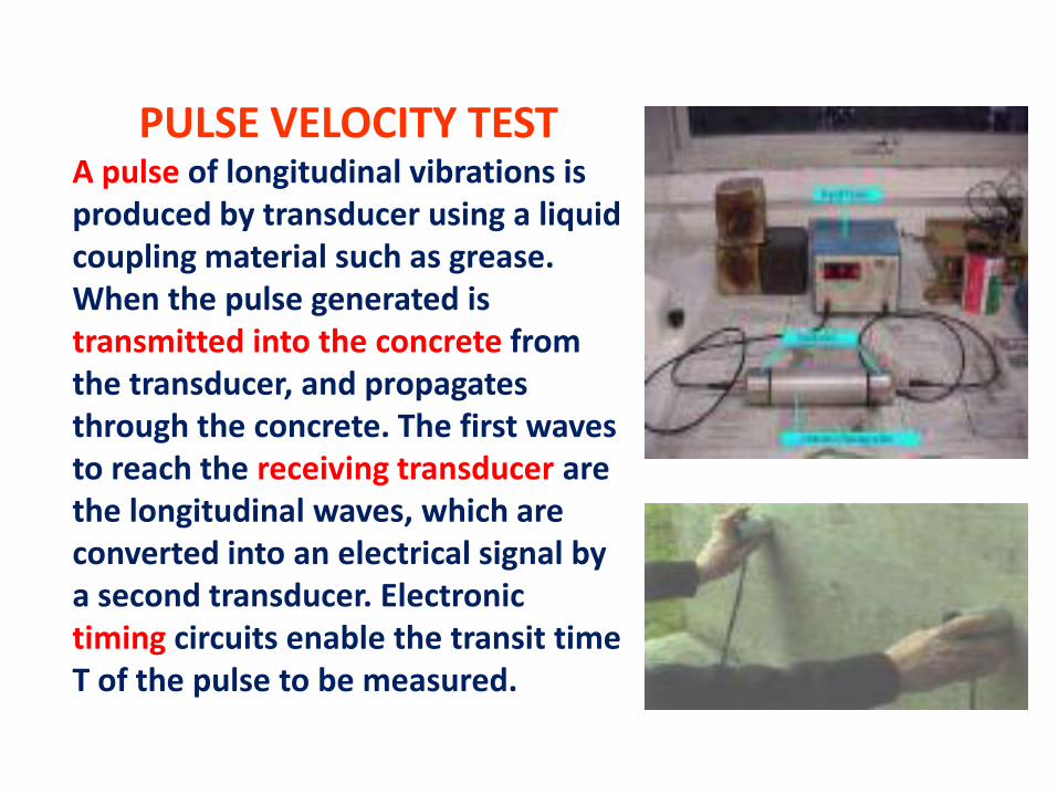
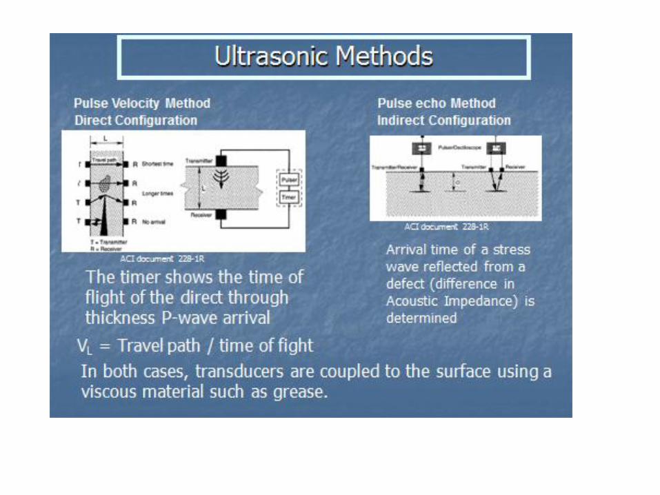
PULSE VELOCITY TESTA pulse of longitudinal vibrations is produced by transducer using a liquid coupling material such as grease. When the pulse generated is transmitted into the concrete from the transducer, and propagates through the concrete. The first waves to reach the receiving transducer are the longitudinal waves, which are converted into an electrical signal by a second transducer. Electronic timing circuits enable the transit time T of the pulse to be measured.
US Army Corpsof Engineers® Engineer Research and Development Center
T
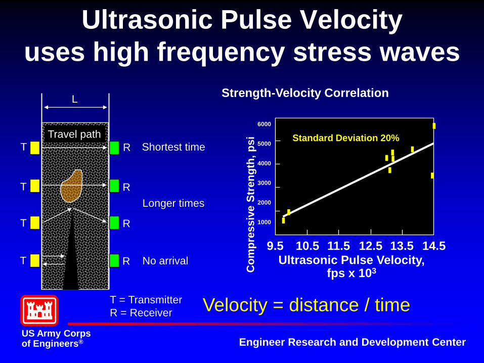
Ultrasonic Pulse Velocity
uses high frequency stress waves
T
T
T
R
R
R
R
L
Travel path
Shortest time
Longer times
No arrival
T = Transmitter
R = ReceiverVelocity = distance / time
6000
5000
4000
3000
2000
1000
Co
mp
ressiv
e S
tren
gth
, p
si
9.5 10.5 11.5 12.5 13.5 14.5Ultrasonic Pulse Velocity,
fps x 103
Standard Deviation 20%
Strength-Velocity Correlation
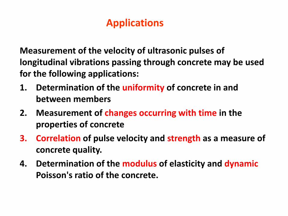
Measurement of the velocity of ultrasonic pulses of longitudinal vibrations passing through concrete may be used for the following applications:
1. Determination of the uniformity of concrete in and between members
2. Measurement of changes occurring with time in the properties of concrete
3. Correlation of pulse velocity and strength as a measure of concrete quality.
4. Determination of the modulus of elasticity and dynamicPoisson's ratio of the concrete.
Applications
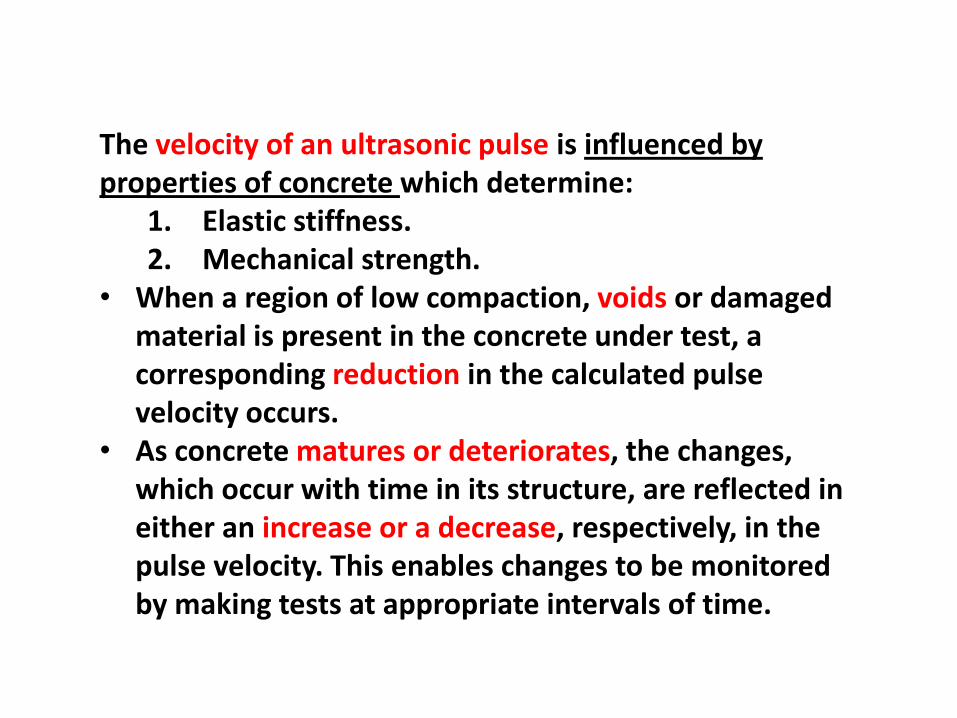
The velocity of an ultrasonic pulse is influenced by properties of concrete which determine:
1. Elastic stiffness.2. Mechanical strength.
• When a region of low compaction, voids or damaged material is present in the concrete under test, a corresponding reduction in the calculated pulse velocity occurs.
• As concrete matures or deteriorates, the changes, which occur with time in its structure, are reflected in either an increase or a decrease, respectively, in the pulse velocity. This enables changes to be monitored by making tests at appropriate intervals of time.
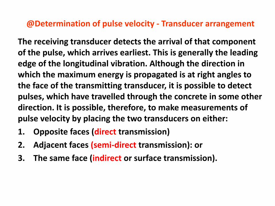
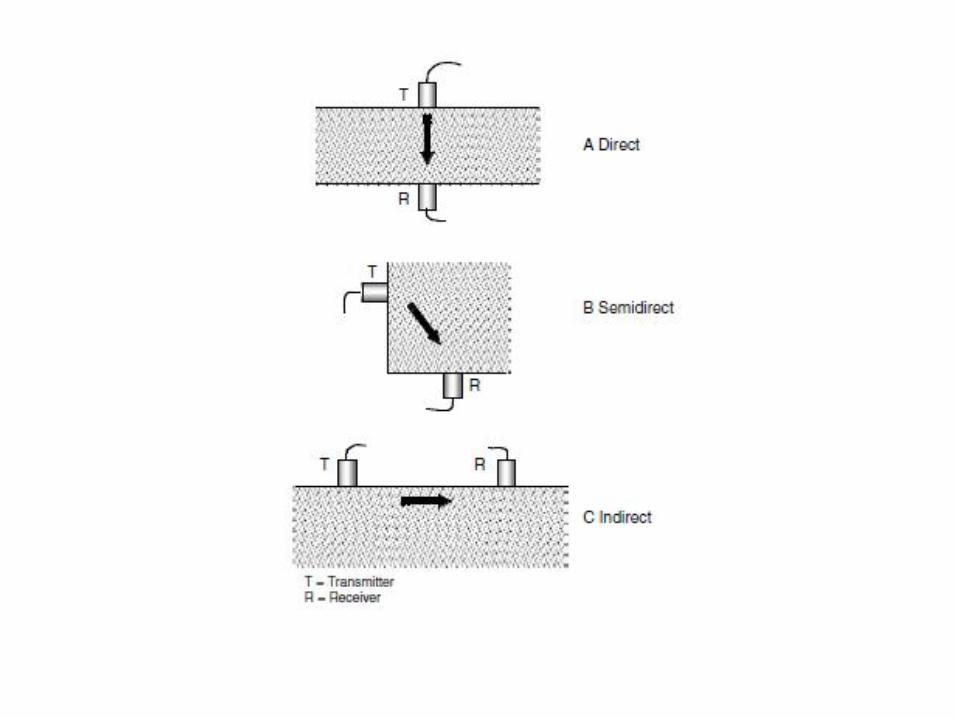
The receiving transducer detects the arrival of that component of the pulse, which arrives earliest. This is generally the leading edge of the longitudinal vibration. Although the direction in which the maximum energy is propagated is at right angles to the face of the transmitting transducer, it is possible to detect pulses, which have travelled through the concrete in some other direction. It is possible, therefore, to make measurements of pulse velocity by placing the two transducers on either:
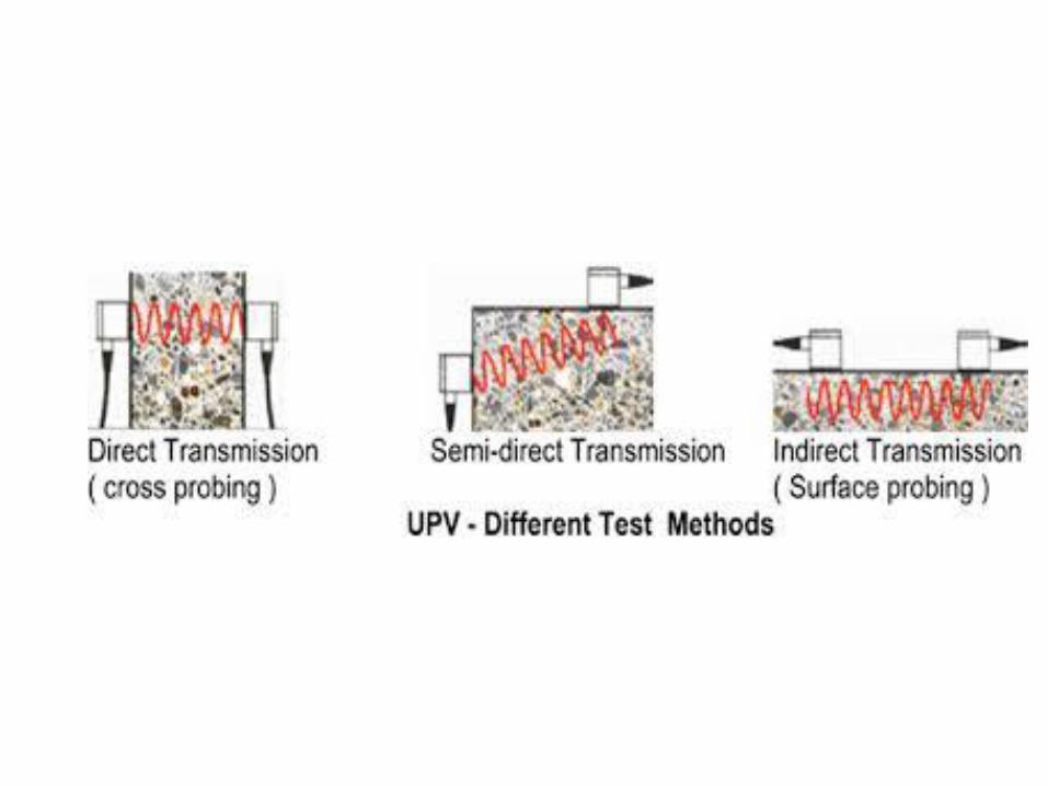
1. Opposite faces (direct transmission)
2. Adjacent faces (semi-direct transmission): or
3. The same face (indirect or surface transmission).
@Determination of pulse velocity - Transducer arrangement
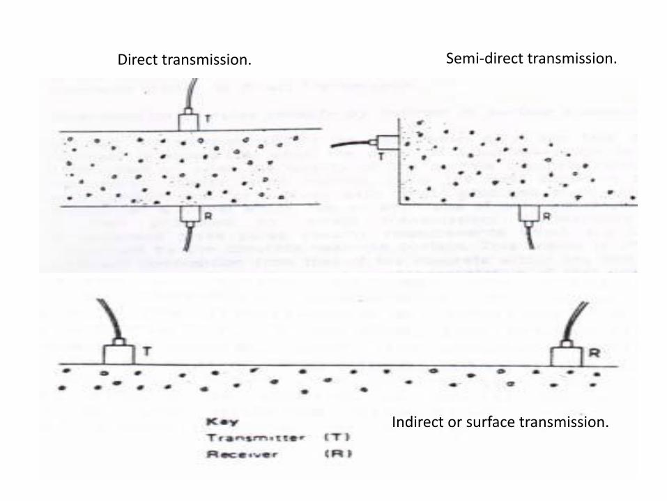
Direct transmission. Semi-direct transmission.
Indirect or surface transmission.
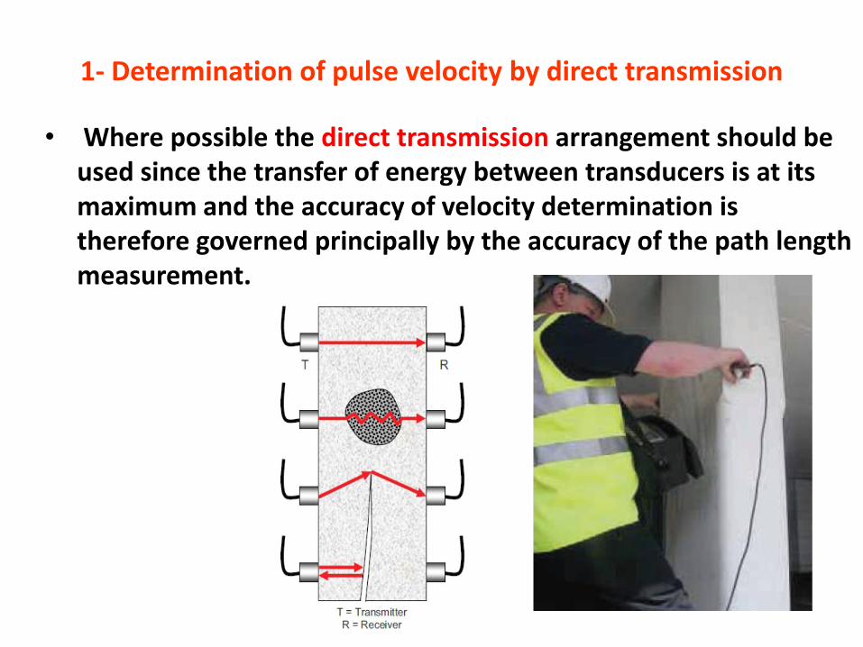
1- Determination of pulse velocity by direct transmission
• Where possible the direct transmission arrangement should be used since the transfer of energy between transducers is at its maximum and the accuracy of velocity determination is therefore governed principally by the accuracy of the path length measurement.
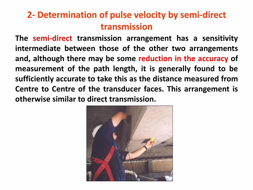
2- Determination of pulse velocity by semi-direct transmission
The semi-direct transmission arrangement has a sensitivityintermediate between those of the other two arrangementsand, although there may be some reduction in the accuracy ofmeasurement of the path length, it is generally found to besufficiently accurate to take this as the distance measured fromCentre to Centre of the transducer faces. This arrangement isotherwise similar to direct transmission.
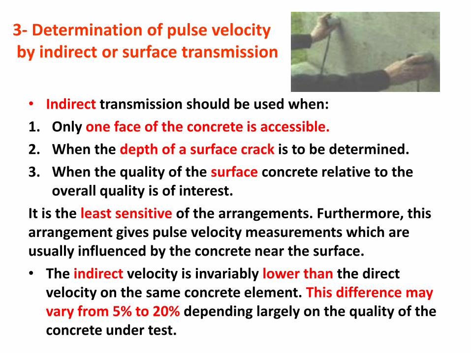
3- Determination of pulse velocityby indirect or surface transmission
• Indirect transmission should be used when:
1. Only one face of the concrete is accessible.
2. When the depth of a surface crack is to be determined.
3. When the quality of the surface concrete relative to the overall quality is of interest.
It is the least sensitive of the arrangements. Furthermore, this arrangement gives pulse velocity measurements which are usually influenced by the concrete near the surface.
• The indirect velocity is invariably lower than the direct velocity on the same concrete element. This difference may vary from 5% to 20% depending largely on the quality of the concrete under test.
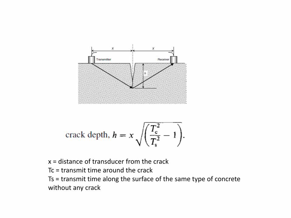
x = distance of transducer from the crackTc = transmit time around the crackTs = transmit time along the surface of the same type of concrete without any crack
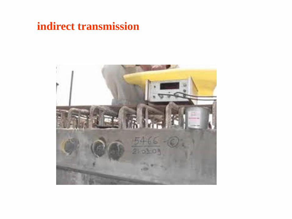
indirect transmission
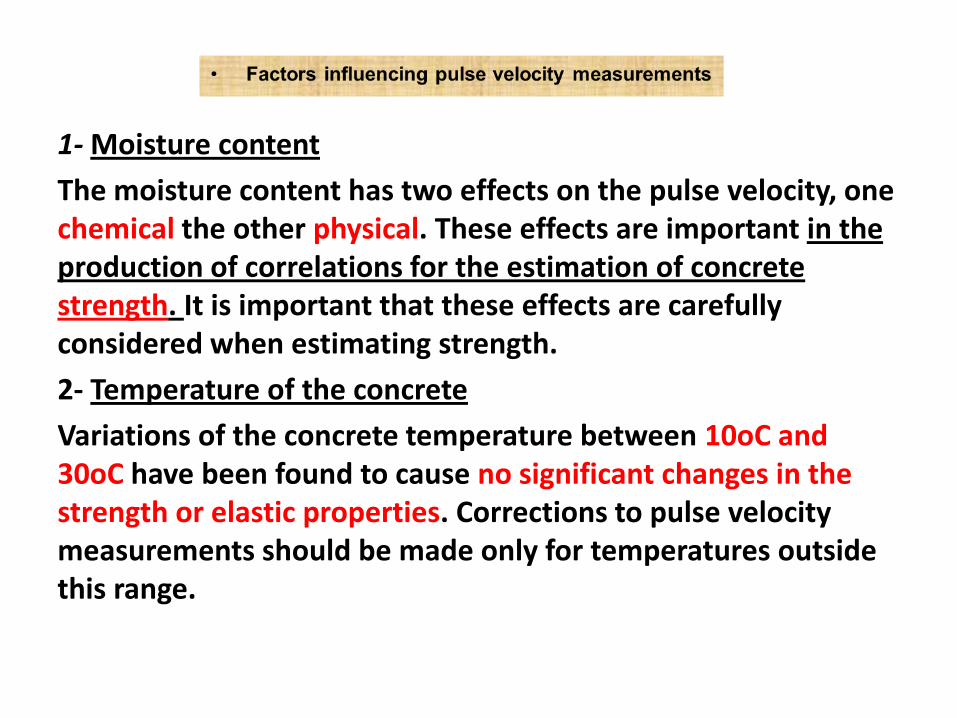
1- Moisture content
The moisture content has two effects on the pulse velocity, one chemical the other physical. These effects are important in the production of correlations for the estimation of concrete strength. It is important that these effects are carefully considered when estimating strength.
2- Temperature of the concrete
Variations of the concrete temperature between 10oC and 30oC have been found to cause no significant changes in the strength or elastic properties. Corrections to pulse velocity measurements should be made only for temperatures outside this range.
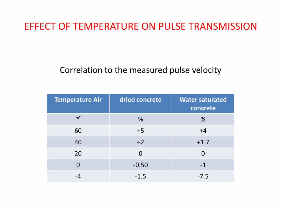
EFFECT OF TEMPERATURE ON PULSE TRANSMISSION
Correlation to the measured pulse velocity
Temperature Air dried concrete Water saturated concrete
oC % %
60 +5 +4
40 +2 +1.7
20 0 0
0 -0.50 -1
-4 -1.5 -7.5
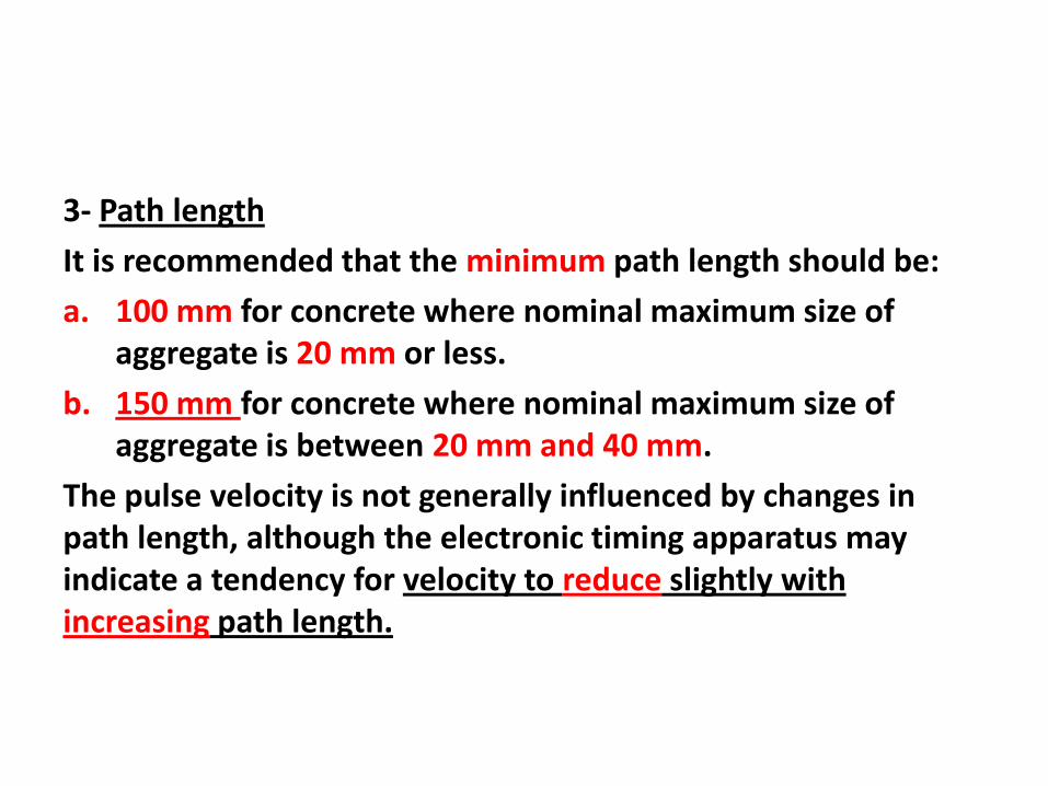
3- Path length
It is recommended that the minimum path length should be:
a. 100 mm for concrete where nominal maximum size of aggregate is 20 mm or less.
b. 150 mm for concrete where nominal maximum size of aggregate is between 20 mm and 40 mm.
The pulse velocity is not generally influenced by changes in path length, although the electronic timing apparatus may indicate a tendency for velocity to reduce slightly with increasing path length.
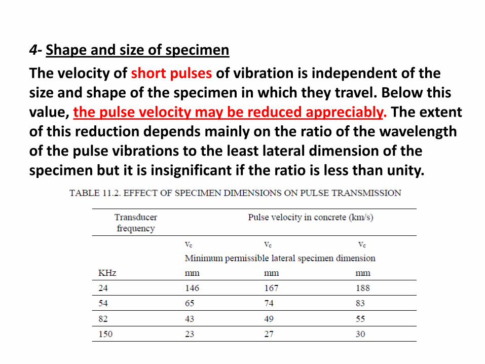
4- Shape and size of specimen
The velocity of short pulses of vibration is independent of the size and shape of the specimen in which they travel. Below this value, the pulse velocity may be reduced appreciably. The extent of this reduction depends mainly on the ratio of the wavelength of the pulse vibrations to the least lateral dimension of the specimen but it is insignificant if the ratio is less than unity.

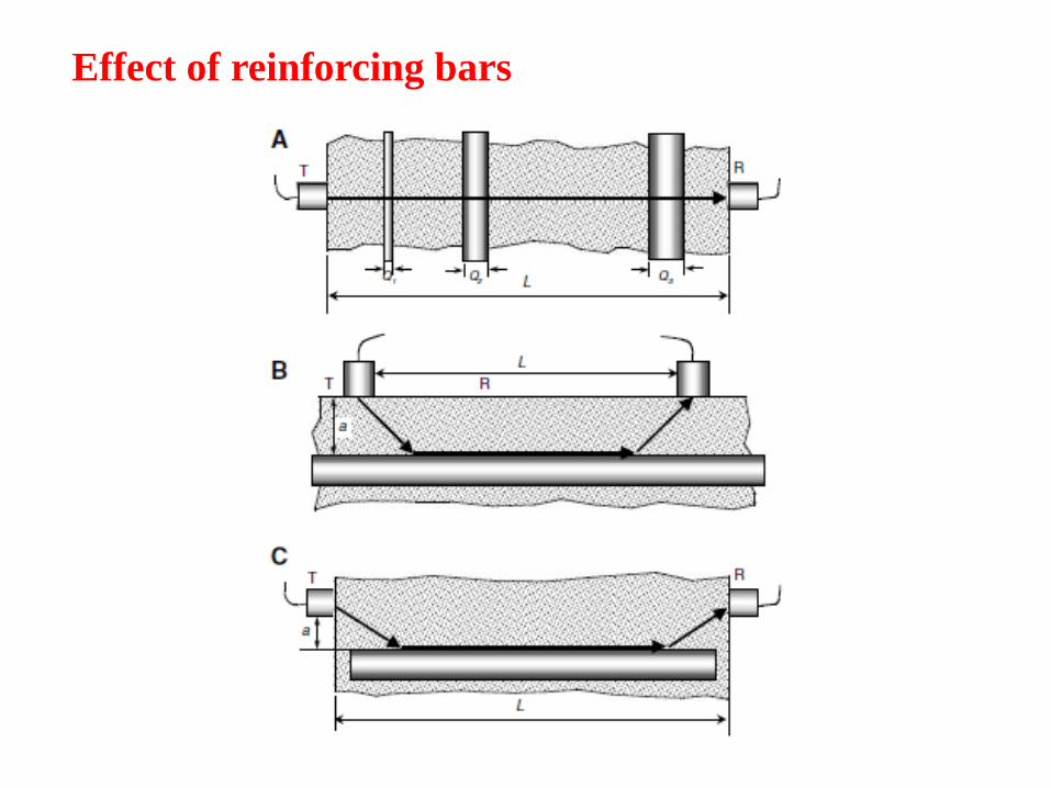
5- Effect of reinforcing bars
• The pulse velocity measured in reinforced concrete is usuallyhigher than in plain concrete of the same composition. Thisis because the pulse velocity in steel may be up to twice thevelocity in plain concrete.
• The apparent increase in pulse velocity depends on theproximity of the measurements to the reinforcing bar, thediameter and number of bars and their orientation withrespect to the propagation path.
• Corrections to measured values to allow for reinforcementwill reduce the accuracy of estimated pulse velocity in theconcrete so that, wherever possible, measurements shouldbe made in such a way that steel does not lie in or close tothe direct path between the transducers.
Effect of reinforcing bars
Concrete uniformity
Measurements of pulse velocity provide a means of studying the homogeneity and for this purpose a system of measuring points which covers uniformly the appropriate volume of concrete in the structure has to be chosen. In a large unit concrete, testing on a 1m grid is usually adequate but, on small units or variable concrete, a finer grid may be necessary. It should be noted that, in cases where the path length is the same throughout the survey, the measured time might be used to assess the concrete uniformity without the need to convert it to velocity. This technique is particularly suitable for surveys where all the measurements are made by indirect measurements.
Pulse velocity measurements are particularly useful to follow
the hardening process, especially during the first 36 h. Here, rapid changes in pulse velocity are associated with physiochemical changes in the cement paste structure, and it is necessary to make measurements at intervals of 1 h or 2 h if these changes are to be followed closely. As the concrete hardens these intervals may be lengthened to 1 day or more after the initial period of 36 h has elapsed.
The relationship between ultrasonic pulse velocity and strength is affected by many factors including:
1. Age
2. Curing conditions
3. Moisture condition
4. Mix proportions
5. Type of aggregate and type of cement.
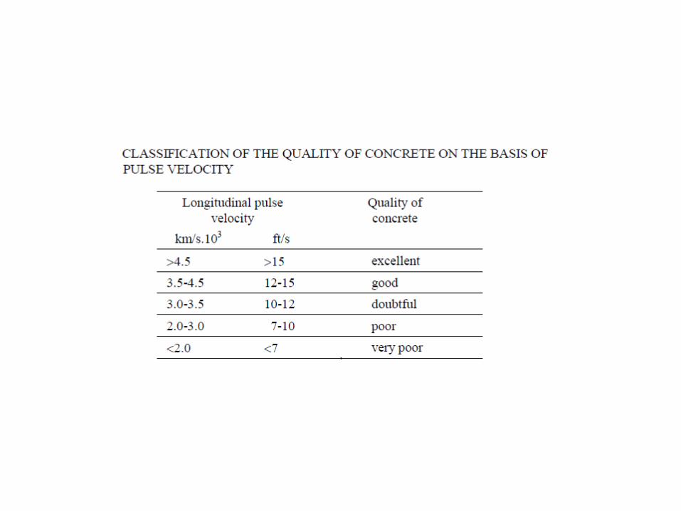
CLASSIFICATION OF THE QUALITY OF CONCRETE ON THE BASIS OF PULSE VELOCITY
• Examples of relationships between pulse velocity andcompressive strength Some figures suggested by Whitehurstfor concrete with a density of approximately 2400kg/m3 aregiven. According to Jones, however, the lower limit for goodquality concrete is between 4.1 and 4.7 km/s. Fig. ---, basedon Jones’ results, illustrates this effect.
• Ultrasonic pulse velocity measurements are not usually usedas a means of quality control on construction sites.Unfortunately there is no satisfactory correlation betweenthe variability of the compression test samples, be cubes orcylinders, and the variability of the pulse velocitymeasurements.
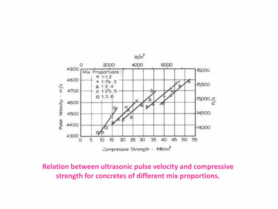
Relation between ultrasonic pulse velocity and compressive strength for concretes of different mix proportions.
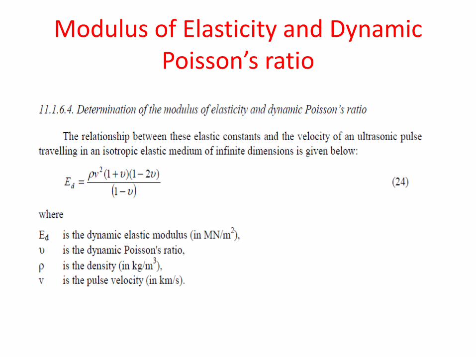
Modulus of Elasticity and Dynamic Poisson’s ratio
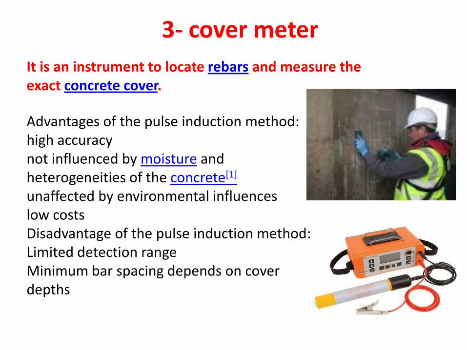
It is an instrument to locate rebars and measure the exact concrete cover.
Advantages of the pulse induction method:high accuracynot influenced by moisture and heterogeneities of the concrete[1]
unaffected by environmental influenceslow costsDisadvantage of the pulse induction method:Limited detection rangeMinimum bar spacing depends on cover depths
3- cover meter
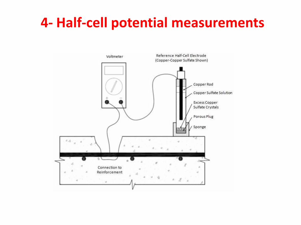
4- Half-cell potential measurements
Half-Cell Potential MeasurementOne can measure the potential difference between a standard portable half-cell, normally a copper/ copper sulphate (Cu/CuSO4) standard reference electrode placed on the surface of the concrete with the steel reinforcement underneath. The reference electrode is connected to the negative end of the voltmeter and the steel reinforcement to the positive.
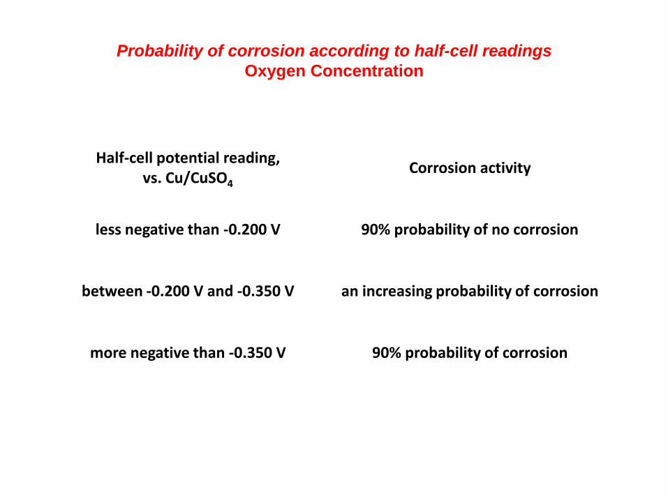
Half-cell potential reading, vs. Cu/CuSO4
Corrosion activity
less negative than -0.200 V 90% probability of no corrosion
between -0.200 V and -0.350 V an increasing probability of corrosion
more negative than -0.350 V 90% probability of corrosion
Probability of corrosion according to half-cell readings
Oxygen Concentration
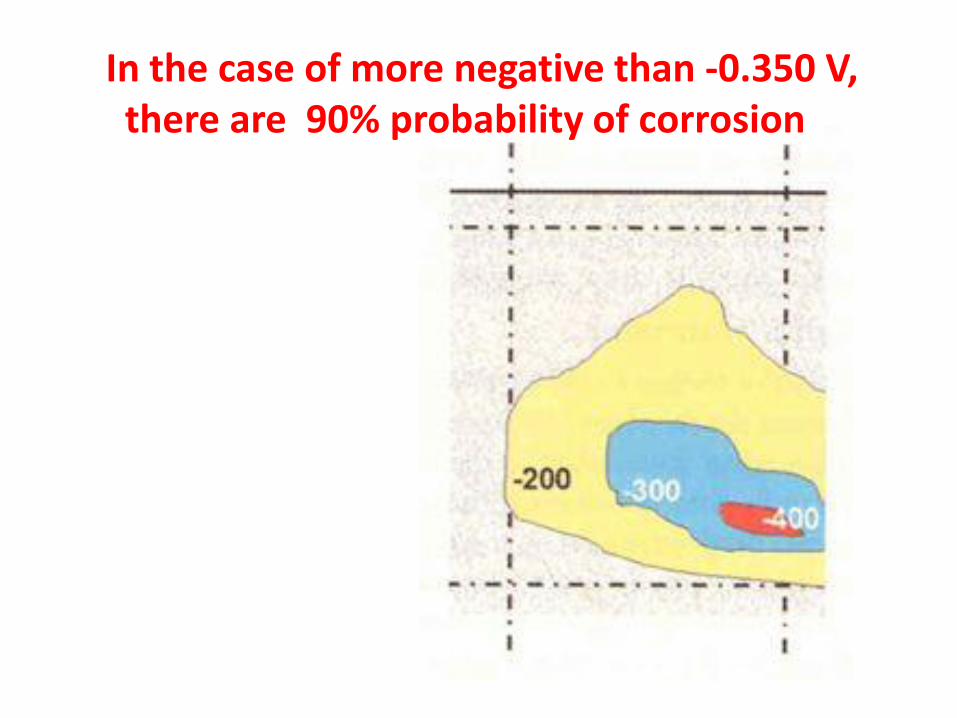
In the case of more negative than -0.350 V,there are 90% probability of corrosion

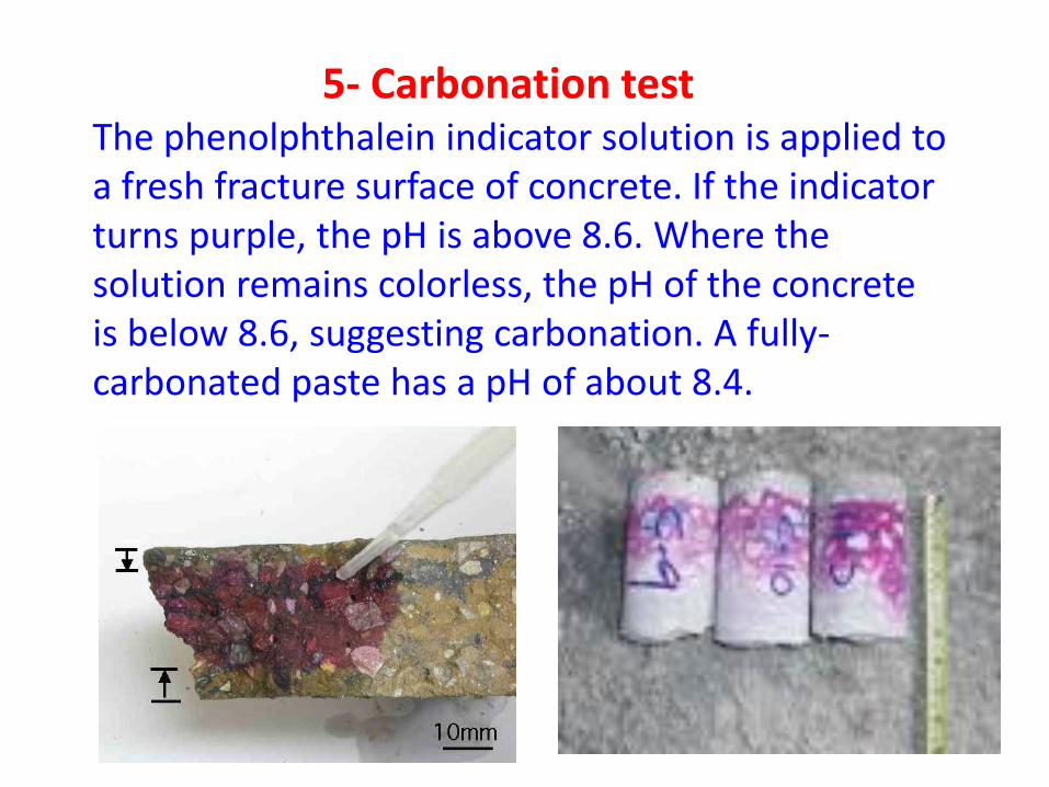
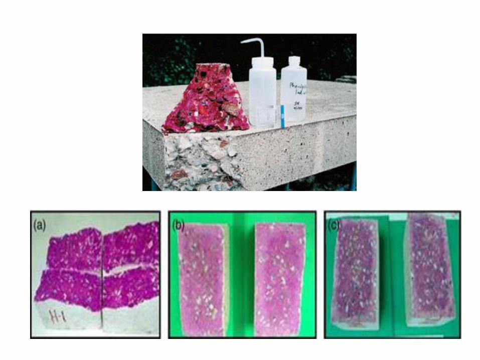
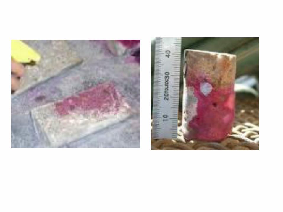
The phenolphthalein indicator solution is applied to a fresh fracture surface of concrete. If the indicator turns purple, the pH is above 8.6. Where the solution remains colorless, the pH of the concrete is below 8.6, suggesting carbonation. A fully-carbonated paste has a pH of about 8.4.
5- Carbonation test
@Evaluation of Compression Test Results
From Cylinders ACI 318
Compress. strength satisfactory if —
1. The average of all sets of three consecutive strength tests equal to or exceed ƒc′ (Specified 28-day compressive strength)
2. No individual strength test (average of 2-cylinders) is more than 3.5 Mpabelow the specified strength.
If results do not meet criteria
• Strength evaluation by drilled cores
55
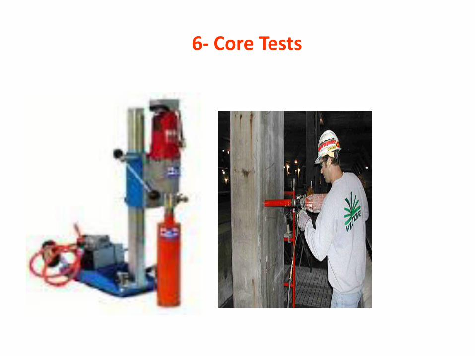
6- Core Tests
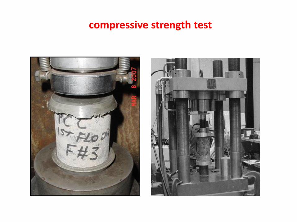
compressive strength test

Evaluation of Compressive Strength of Cores
1. Ave. strength of 3-cores is at least 85% of ƒc′ (Specified 28-day compressive strength)
2. No single core less than 75% of ƒc′
Concrete represented by the cores are
considered structurally adequate if —
58
59
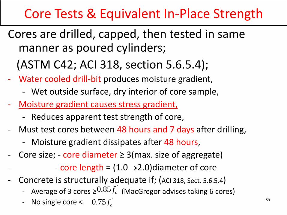
Core Tests & Equivalent In-Place Strength
Cores are drilled, capped, then tested in same manner as poured cylinders;
(ASTM C42; ACI 318, section 5.6.5.4);- Water cooled drill-bit produces moisture gradient,
- Wet outside surface, dry interior of core sample,
- Moisture gradient causes stress gradient,
- Reduces apparent test strength of core,
- Must test cores between 48 hours and 7 days after drilling,
- Moisture gradient dissipates after 48 hours,
- Core size; - core diameter ≥ 3(max. size of aggregate)
- - core length = (1.02.0)diameter of core
- Concrete is structurally adequate if; (ACI 318, Sect. 5.6.5.4)- Average of 3 cores ≥ (MacGregor advises taking 6 cores)
- No single core <
'85.0 cf'75.0 cf
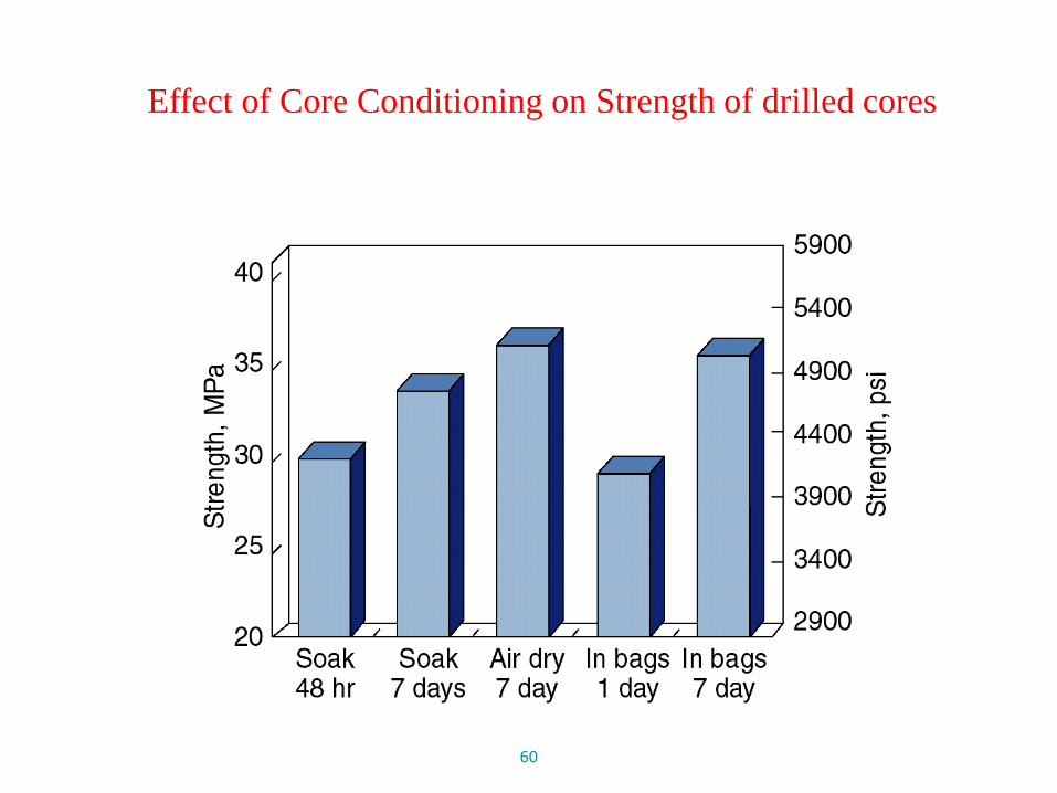
Effect of Core Conditioning on Strength of drilled cores
60
61
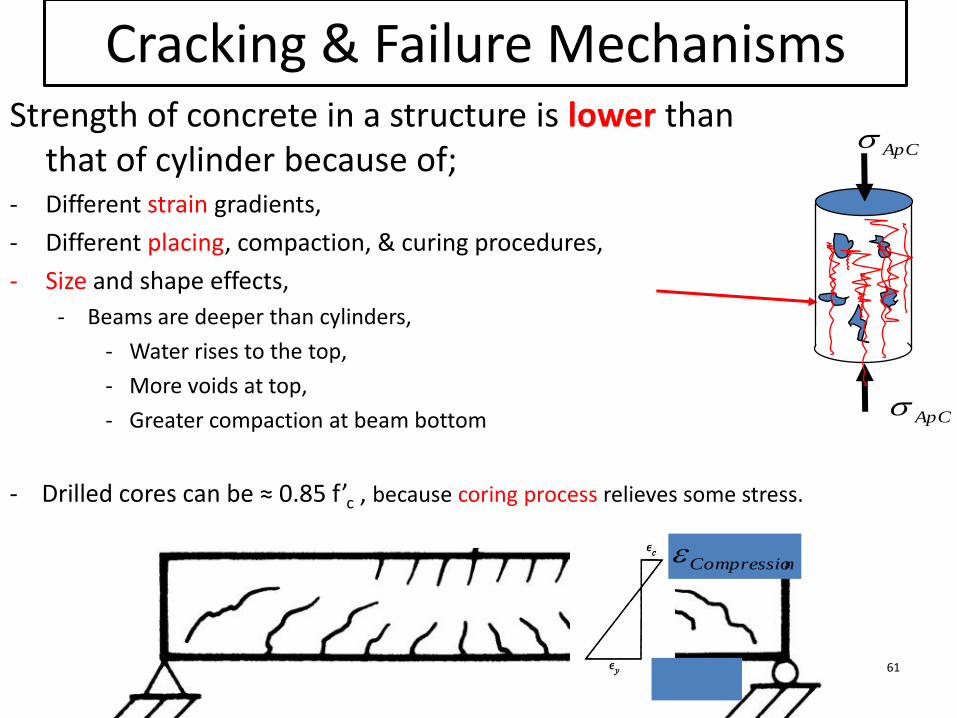
Cracking & Failure Mechanisms Strength of concrete in a structure is lower than
that of cylinder because of;- Different strain gradients,
- Different placing, compaction, & curing procedures,
- Size and shape effects,
- Beams are deeper than cylinders,
- Water rises to the top,
- More voids at top,
- Greater compaction at beam bottom ApC
ApC
nCompressio
- Drilled cores can be ≈ 0.85 f’c , because coring process relieves some stress.

62
Core Tests & Equivalent In-Place Strength
In-place strength ≠ (core strength)/0.85 ;
MacGregor proposes the following relationships:
= equivalent specified strength, used in design calculations,
= equivalent in-place strength,
= mean equivalent in-place strength,
= standard deviation for equivalent in-place strength,
= core test strength,
'
ceqf
cisf
cisf
ciss
coref
22222
/
2
2
12
' 282.1 dmcrdiadlciscis
cisceq VVVVVfn
skfkf
63
Core Tests & Equivalent In-Place Strength
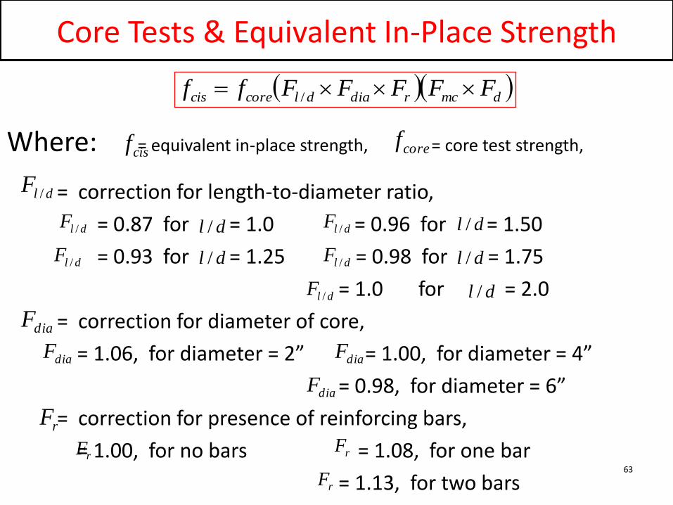
Where: = equivalent in-place strength, = core test strength,
= correction for length-to-diameter ratio,
= 0.87 for = 1.0 = 0.96 for = 1.50
= 0.93 for = 1.25 = 0.98 for = 1.75
= 1.0 for = 2.0
= correction for diameter of core,
= 1.06, for diameter = 2” = 1.00, for diameter = 4”
= 0.98, for diameter = 6”
= correction for presence of reinforcing bars,
= 1.00, for no bars = 1.08, for one bar
= 1.13, for two bars
dlF /
dmcrdiadlcorecis FFFFFff /
dlF /
dlF /
dlF /
dlF /
dlF /dl /
dl /
dl /
dl /
dl /
coref
diaF
diaF diaF
diaF
rF
rF
rF
rF
cisf
64
Core Tests & Equivalent In-Place Strength
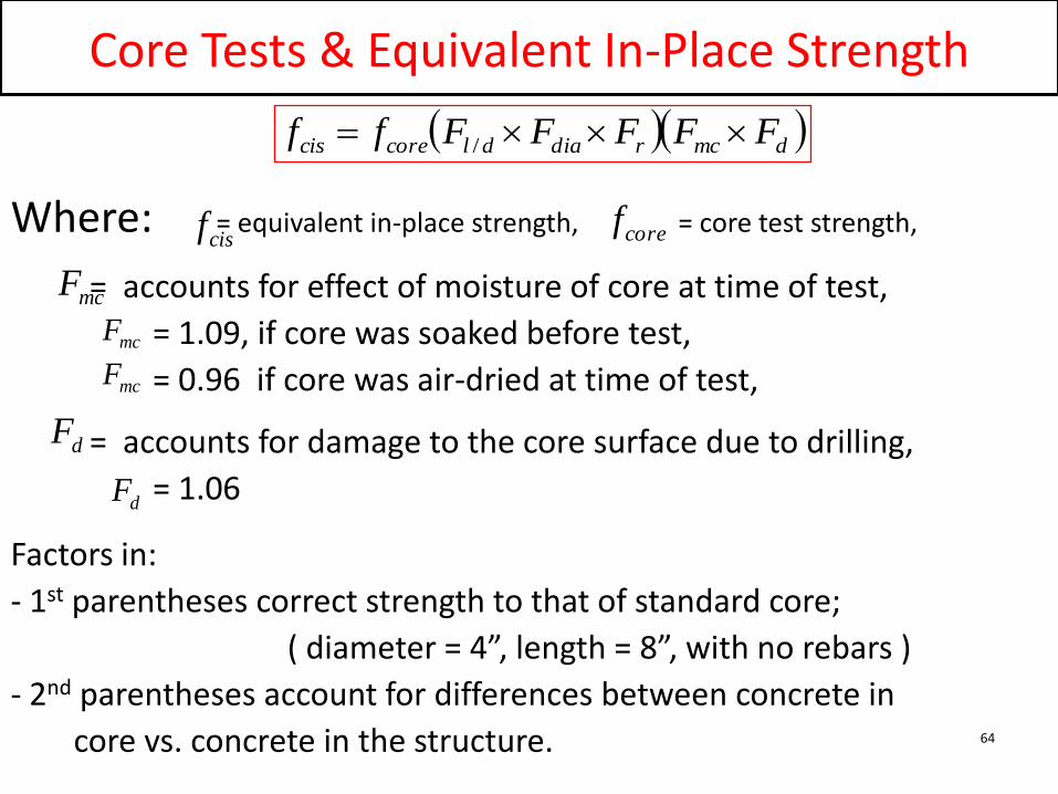
Where: = equivalent in-place strength, = core test strength,
= accounts for effect of moisture of core at time of test,
= 1.09, if core was soaked before test,
= 0.96 if core was air-dried at time of test,
= accounts for damage to the core surface due to drilling,
= 1.06
Factors in:
- 1st parentheses correct strength to that of standard core;
( diameter = 4”, length = 8”, with no rebars )
- 2nd parentheses account for differences between concrete in
core vs. concrete in the structure.
mcF
dmcrdiadlcorecis FFFFFff /
mcF
coref
dF
mcF
dF
cisf
65
Core Tests & Equivalent In-Place Strength
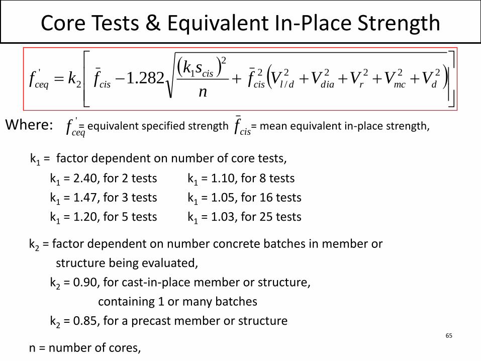
Where: = equivalent specified strength = mean equivalent in-place strength,
k1 = factor dependent on number of core tests,
k1 = 2.40, for 2 tests k1 = 1.10, for 8 tests
k1 = 1.47, for 3 tests k1 = 1.05, for 16 tests
k1 = 1.20, for 5 tests k1 = 1.03, for 25 tests
k2 = factor dependent on number concrete batches in member or
structure being evaluated,
k2 = 0.90, for cast-in-place member or structure,
containing 1 or many batches
k2 = 0.85, for a precast member or structure
n = number of cores,
22222
/
2
2
12
' 282.1 dmcrdiadlciscis
cisceq VVVVVfn
skfkf
'
ceqf cisf
66
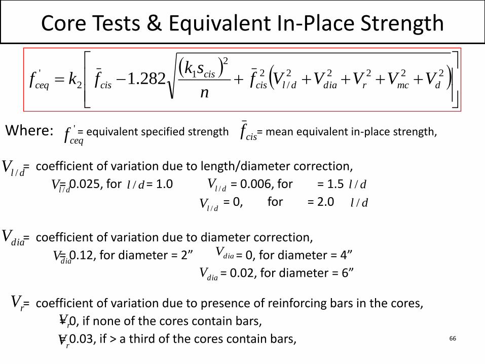
Core Tests & Equivalent In-Place Strength
Where: = equivalent specified strength = mean equivalent in-place strength,
= coefficient of variation due to length/diameter correction,
= 0.025, for = 1.0 = 0.006, for = 1.5
= 0, for = 2.0
= coefficient of variation due to diameter correction,
= 0.12, for diameter = 2” = 0, for diameter = 4”
= 0.02, for diameter = 6”
= coefficient of variation due to presence of reinforcing bars in the cores,
= 0, if none of the cores contain bars,
= 0.03, if > a third of the cores contain bars,
22222
/
2
2
12
' 282.1 dmcrdiadlciscis
cisceq VVVVVfn
skfkf
'
ceqf cisf
dl / dl /
dl /
dlV /
dlV / dlV /
dlV /
diaV
diaV diaV
diaV
rV
rV
rV
67
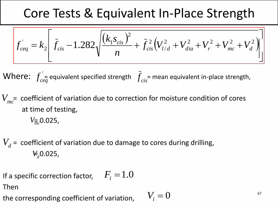
Core Tests & Equivalent In-Place Strength
Where: = equivalent specified strength = mean equivalent in-place strength,
= coefficient of variation due to correction for moisture condition of cores
at time of testing,
= 0.025,
= coefficient of variation due to damage to cores during drilling,
= 0.025,
If a specific correction factor,
Then
the corresponding coefficient of variation,
22222
/
2
2
12
' 282.1 dmcrdiadlciscis
cisceq VVVVVfn
skfkf
'
ceqfcisf
mcV
mcV
dV
dV
0iV
0.1iF
68
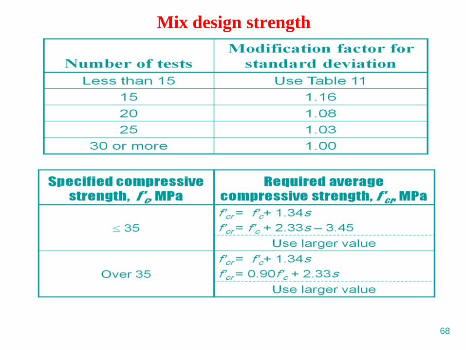
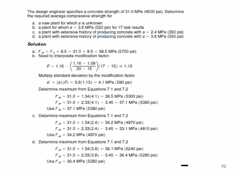
Mix design strength
69
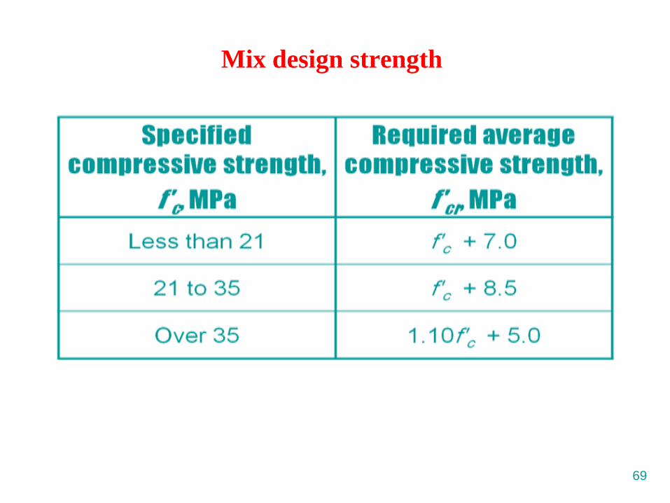
Mix design strength
70
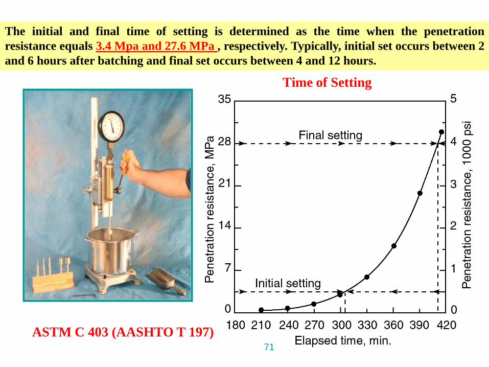
Time of Setting
ASTM C 403 (AASHTO T 197)71
The initial and final time of setting is determined as the time when the penetration
resistance equals 3.4 Mpa and 27.6 MPa , respectively. Typically, initial set occurs between 2
and 6 hours after batching and final set occurs between 4 and 12 hours.