Embed Size (px)
Citation preview
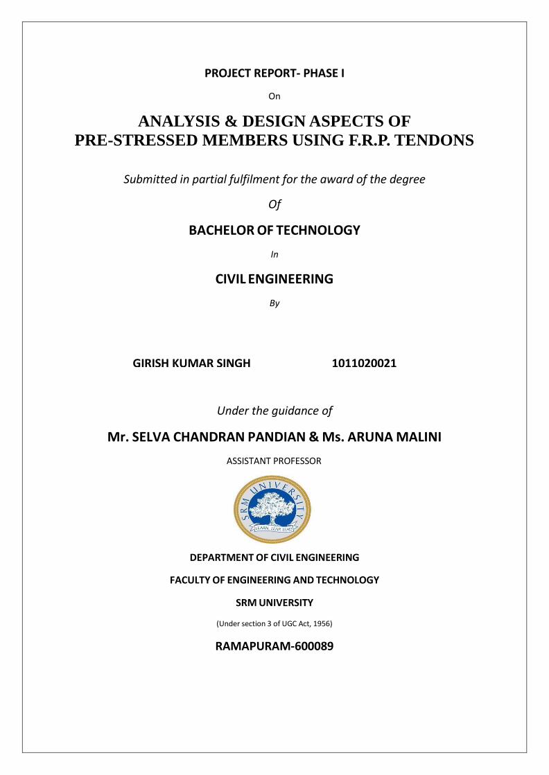
PROJECT REPORT- PHASE I
On
ANALYSIS & DESIGN ASPECTS OF PRE-STRESSED MEMBERS USING F.R.P. TENDONS
Submitted in partial fulfilment for the award of the degree
Of
BACHELOR OF TECHNOLOGY In
CIVIL ENGINEERING By
GIRISH KUMAR SINGH 1011020021
Under the guidance of
Mr. SELVA CHANDRAN PANDIAN & Ms. ARUNA MALINI ASSISTANT PROFESSOR
DEPARTMENT OF CIVIL ENGINEERING
FACULTY OF ENGINEERING AND TECHNOLOGY
SRM UNIVERSITY
(Under section 3 of UGC Act, 1956)
RAMAPURAM-600089
LIST OF CONTENTS
i
ii
iii
iii
Iv
CHAPTHER NO. TITLE PA GE NO.
ACKNOWLEDGEMENT
ABSTRACT
LIST OF TABLE
LIST OF FIGURES
LIST OF SYMBOLS
1. INTRODUCTION 1
1. 1 Pre-Stressing 2
1. 2 Pre-Stress Concrete 5
1. 3 Pre-Stressed Beam. 6
1. 4 Pre-Stressing Steel 7
1. 5 Anchorage 9
1. 6 Losses in Pre-stressing 17
2. F
P
IBRE REINFORCED POLYMER FOR
RESTRESSING
19
2. 1 Literature Survey 20
2. 2 Historical Development And Use of FRP
Reinforcement
21
2. 3 Design Guidelines And Technical Committees 23
2. 4 Research Efforts 23
3. D ESIGN CRITERIA 26
3.1 Design of Pre-Stress Beam
3.1.1 Using Steel 27
3.1.2 Using FRP 30
3.2 Calculation of Losses
3.2.1 For Steel 33
3.2.2 For FRP 37
3.3 Anchorage Design 40
4. ANALYSIS RESULTS FROM ANSYS 41
CONCLUSION OF THE PROJECT 44
REFERENCES 46

ACKNOWLEDGEMENT
The undersigned wishes to express his sincere gratitude to Er. BabuRajendran A.G.M of
Chennai metro underground section phase II for providing the opportunity to work under Er.
SelvaChandranPandian of Mott Macdonald, Chennai. He is equally thankful to Er.
SelvaChandranPandian of Mott Macdonald, Chennai for giving his precious time and
providing guidance in the preparation of this project report. Despite his busy schedule, he has
been ever ready to find time for the problem and doubts for this report.
He is also very thankful to Ms.ArunaMalini for providing guidance for the completion of this
project report.

ABSTRACT
The purpose of this investigation is mainly a brief explanation about the advantages of FRP
over steel. The various uses and advantages of FRP are explained in this project. In this
project, we have taken a section of 3m length, 200mm width and 300mm depth and using a
parabolic tendon of eccentricity 100mm at the centre. We have design the section for FRP as
well as steel with the above data. The final stresses obtained is being verified with the help of
Ansys software. We have shown the result of steel straight tendon only in this mini project.
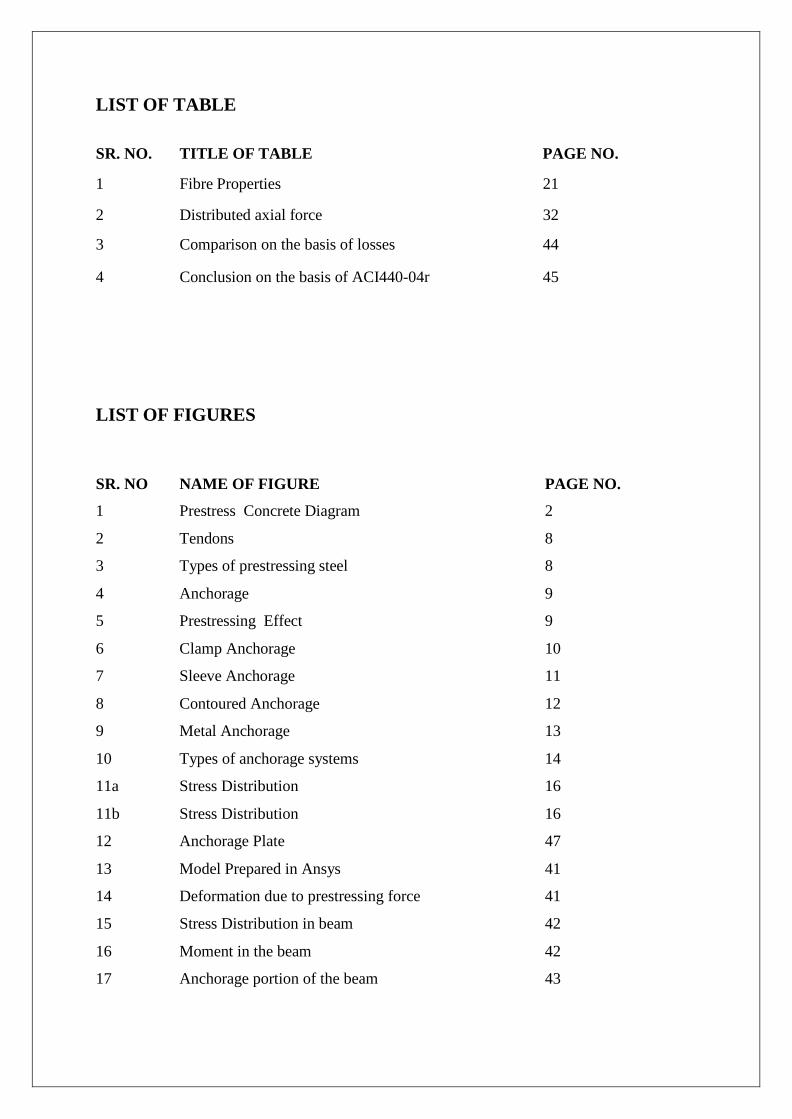
LIST OF TABLE
SR. NO. TITLE OF TABLE PAGE NO.
1 Fibre Properties 21
2 Distributed axial force 32
3 Comparison on the basis of losses 44
4 Conclusion on the basis of ACI440-04r 45
LIST OF FIGURES
SR. NO NAME OF FIGURE PAGE NO.
1 Prestress Concrete Diagram 2
2 Tendons 8
3 Types of prestressing steel 8
4 Anchorage 9
5 Prestressing Effect 9
6 Clamp Anchorage 10
7 Sleeve Anchorage 11
8 Contoured Anchorage 12
9 Metal Anchorage 13
10 Types of anchorage systems 14
11a Stress Distribution 16
11b Stress Distribution 16
12 Anchorage Plate 47
13 Model Prepared in Ansys 41
14 Deformation due to prestressing force 41
15 Stress Distribution in beam 42
16 Moment in the beam 42
17 Anchorage portion of the beam 43
CHAPTER 1
INTRODUCTION
1.1 PRE-STRESSING.
1.2 PRE-STRESS CONCRETE.
1.3 PRE-STRESSED BEAM.
1.4 PRE-STRESSING STEEL.
1.5 ANCHORAGE.
1.6 LOSSES IN PRE-STRESSING.
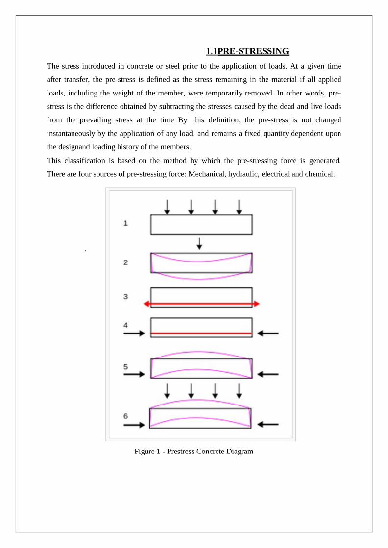
1.1 PRE-STRESSING The stress introduced in concrete or steel prior to the application of loads. At a given time
after transfer, the pre-stress is defined as the stress remaining in the material if all applied
loads, including the weight of the member, were temporarily removed. In other words, pre-
stress is the difference obtained by subtracting the stresses caused by the dead and live loads
from the prevailing stress at the time By this definition, the pre-stress is not changed
instantaneously by the application of any load, and remains a fixed quantity dependent upon
the designand loading history of the members.
This classification is based on the method by which the pre-stressing force is generated.
There are four sources of pre-stressing force: Mechanical, hydraulic, electrical and chemical.
Figure 1 - Prestress Concrete Diagram
EXTERNAL OR INTERNAL PRE-STRESSING
This classification is based on the location of the pre-stressing tendon with respect to the
concrete section.
PRE-TENSIONING OR POST-TENSIONING
This is the most important classification and is based on the sequence of casting the concrete
and applying tension to the tendons.
LINEAR OR CIRCULAR PRE-STRESSING
This classification is based on the shape of the member pre-stressed.
FULL, LIMITED OR PARTIAL PRE-STRESSING
Based on the amount of pre-stressing force, three types of pre-stressing are defined.
UNIAXIAL, BIAXIAL OR MULTI-AXIAL PRE-STRESSING
As the names suggest, the classification is based on the directions of pre-stressing a member.
The individual types of pre-stressing are explained next.
SOURCE OF PRE-STRESSING FORCE HYDRAULIC PRE-STRESSING
This is the simplest type of pre-stressing, producing large pre-stressing forces. The hydraulic
jack used for the tensioning of tendons, comprises of calibrated pressure gauges which
directly indicate the magnitude of force developed during the tensioning.
MECHANICAL PRE-STRESSING
In this type of pre-stressing, the devices includes weights with or without lever transmission,
geared transmission in conjunction with pulley blocks, screw jacks with or without gear
drives and wire-winding machines. This type of pre-stressing is adopted for mass scale
production.
ELECTRICAL PRE-STRESSING
In this type of pre-stressing, the steel wires are electrically heated and anchored before
placing concrete in the moulds. This type of pre-stressing is also known as thermo-electric
pre-stressing.
EXTERNAL OR INTERNAL PRESTRESSING EXTERNAL PRESTRESSING
When the prestressing is achieved by elements located outside the concrete, it is called
external prestressing. The tendons can lie outside the member (for example in I-girders or
walls) or inside the hollow space of a box girder. This technique is adopted in bridges and
strengthening of buildings.
INTERNAL PRESTRESSING
When the prestressing is achieved by elements located inside the concrete member
(commonly, by embedded tendons), it is called internal prestressing. Most of the applications
of prestressing are internal prestressing.
PRE-TENSIONING OR POST-TENSIONING PRE-TENSIONING
The tension is applied to the tendons before casting of the concrete. The pre-compression is
transmitted from steel to concrete through bond over the transmission length near the ends.
POST-TENSIONING
The tension is applied to the tendons (located in a duct) after hardening of the concrete. The
pre-compression is transmitted from steel to concrete by the anchorage device (at the end
blocks).
LINEAR OR CIRCULAR PRESTRESSING LINEAR PRESTRESSING
When the prestressed members are straight or flat, in the direction of prestressing, the
prestressing is called linear prestressing. For example, prestressing of beams, piles, poles and
slabs. The profile of the prestressing tendon may be curved.
CIRCULAR PRESTRESSING
When the prestressed members are curved, in the direction of prestressing, the prestressing is
called circular prestressing. For example, circumferential prestressing of tanks, silos, pipes
and similar structures.
FULL, LIMITED OR PARTIAL PRESTRESSING FULL PRESTRESSING
When the level of prestressing is such that no tensile stress is allowed in concrete under
service loads, it is called Full Prestressing (Type 1, as per IS:1343 - 1980).
LIMITED PRESTRESSING
When the level of prestressing is such that the tensile stress under service loads is within the
cracking stress of concrete, it is called Limited Prestressing (Type 2).
PARTIAL PRESTRESSING
When the level of prestressing is such that under tensile stresses due to service loads, the
crack width is within the allowable limit, it is called Partial Prestressing (Type 3).
UNIAXIAL, BIAXIAL OR MULTIAXIAL PRESTRESSING UNIAXIAL PRESTRESSING
When the prestressing tendons are parallel to one axis, it is called Uniaxial Prestressing. For
example, longitudinal prestressing of beams.
BIAXIAL PRESTRESSING
When there are prestressing tendons parallel to two axes, it is called Biaxial Prestressing.
MULTIAXIAL PRESTRESSING
When the prestressing tendons are parallel to more than two axes, it is called Multiaxial
Prestressing. For example, prestressing of domes.
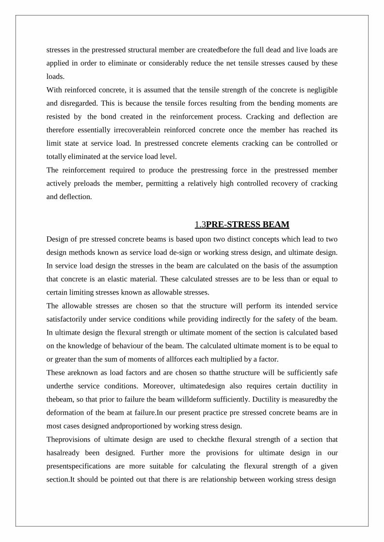
1.2PRE-STRESS CONCRETE Concrete is strong in compression, but weak in tension its tensile strength varies from 8 to
14% of its compressive strength. Due to such a low tensile capacity flexural cracks develop at
early stages of loading. In order to reduce or prevent such cracks from developing, a
concentric or eccentric force is imposed in the longitudinal direction of the structural element.
This force prevents the cracks from developing by eliminating or considerably reducing the
tensile stresses at the critical mid span and support sections at service load thereby raising the
bending, shear, and torsional capacities of the sections.
The sections are then able to behave elastically and almost the full capacity of the concrete in
compression can be efficiently utilized across the entire depth of the concrete sections when
all loads act on the structure. Such an imposed longitudinal force is termed a prestressing
force that is a compressive force that prestresses the sections along the span of the structural
element prior to the application of the transverse gravity dead and live loads or transient
horizontal live loads.
The type of prestressing force involved together with its magnitude are determined mainly on
the basis of the type of system to be constructed and the span length. As a result, permanent
stresses in the prestressed structural member are createdbefore the full dead and live loads are
applied in order to eliminate or considerably reduce the net tensile stresses caused by these
loads.
With reinforced concrete, it is assumed that the tensile strength of the concrete is negligible
and disregarded. This is because the tensile forces resulting from the bending moments are
resisted by the bond created in the reinforcement process. Cracking and deflection are
therefore essentially irrecoverablein reinforced concrete once the member has reached its
limit state at service load. In prestressed concrete elements cracking can be controlled or
totally eliminated at the service load level.
The reinforcement required to produce the prestressing force in the prestressed member
actively preloads the member, permitting a relatively high controlled recovery of cracking
and deflection.
1.3PRE-STRESS BEAM Design of pre stressed concrete beams is based upon two distinct concepts which lead to two
design methods known as service load de-sign or working stress design, and ultimate design.
In service load design the stresses in the beam are calculated on the basis of the assumption
that concrete is an elastic material. These calculated stresses are to be less than or equal to
certain limiting stresses known as allowable stresses.
The allowable stresses are chosen so that the structure will perform its intended service
satisfactorily under service conditions while providing indirectly for the safety of the beam.
In ultimate design the flexural strength or ultimate moment of the section is calculated based
on the knowledge of behaviour of the beam. The calculated ultimate moment is to be equal to
or greater than the sum of moments of allforces each multiplied by a factor.
These areknown as load factors and are chosen so thatthe structure will be sufficiently safe
underthe service conditions. Moreover, ultimatedesign also requires certain ductility in
thebeam, so that prior to failure the beam willdeform sufficiently. Ductility is measuredby the
deformation of the beam at failure.In our present practice pre stressed concrete beams are in
most cases designed andproportioned by working stress design.
Theprovisions of ultimate design are used to checkthe flexural strength of a section that
hasalready been designed. Further more the provisions for ultimate design in our
presentspecifications are more suitable for calculating the flexural strength of a given
section.It should be pointed out that there is are relationship between working stress design
andultimate design. Although they have differentbases, in fulfilling the objective of one,
theobjective of the other is satisfied to a certain extent.It can be shown that the provisions
ofultimate design can be used to proportion asection with a more rigorous control of ductility.
The provisions of working stress design can then be used to check working stressesin the
section so designed.
Further more rational design of a section is considerablysimpler by ultimate design than by
service Load design.The purpose of this study is to develop amethod by which a prestressed
concrete beam canbe proportioned by the provisions of ultimatedesign. It is intended to show
the importanceof ductility in its influence upon the dimensions of the beam. In addition it is
intended to study the influence of compression steelon ductility and the proportions of a
section.
We will consider a simply supported bonded beam and assume that the strength of thebeam is
measured by flexure. We will assume that the only loads acting in addition tothe prestressing
force, are the weight of the beam the superimposed dead load and live load.
1.4 PRESTRESSING STEEL The development of prestressed concrete was influenced by the invention of high strength
steel. It is an alloy of iron, carbon, manganese and optional materials. The following material
describes the types and properties of prestressing steel.
In addition to prestressing steel conventional non-prestressed reinforcement is used for
flexural capacity (optional) shear capacity, temperature and shrinkage requirements. The
properties of steel for non-prestressed reinforcement are not covered in this section. It is
expected that the student of this course is familiar with the conventional reinforcement.
WIRES A prestressing wire is a single unit made of steel. The nominal diameters of the wires are 2.5,
3.0, 4.0, 5.0, 7.0 and 8.0 mm. The different types of wires are as follows.
1) Plain wire: No indentations on the surface.
2) Indented wire: There are circular or elliptical indentations on the surface. STRANDS A few wires are spun together in a helical form to form a prestressing strand. The different
types of strands are as follows.
1) Two-wire strand: Two wires are spun together to form the strand.
2) Three-wire strand: Three wires are spun together to form the strand.
3) Seven-wire strand: In this type of strand, six wires are spun around a central wire. The
central wire is larger than the other wires.
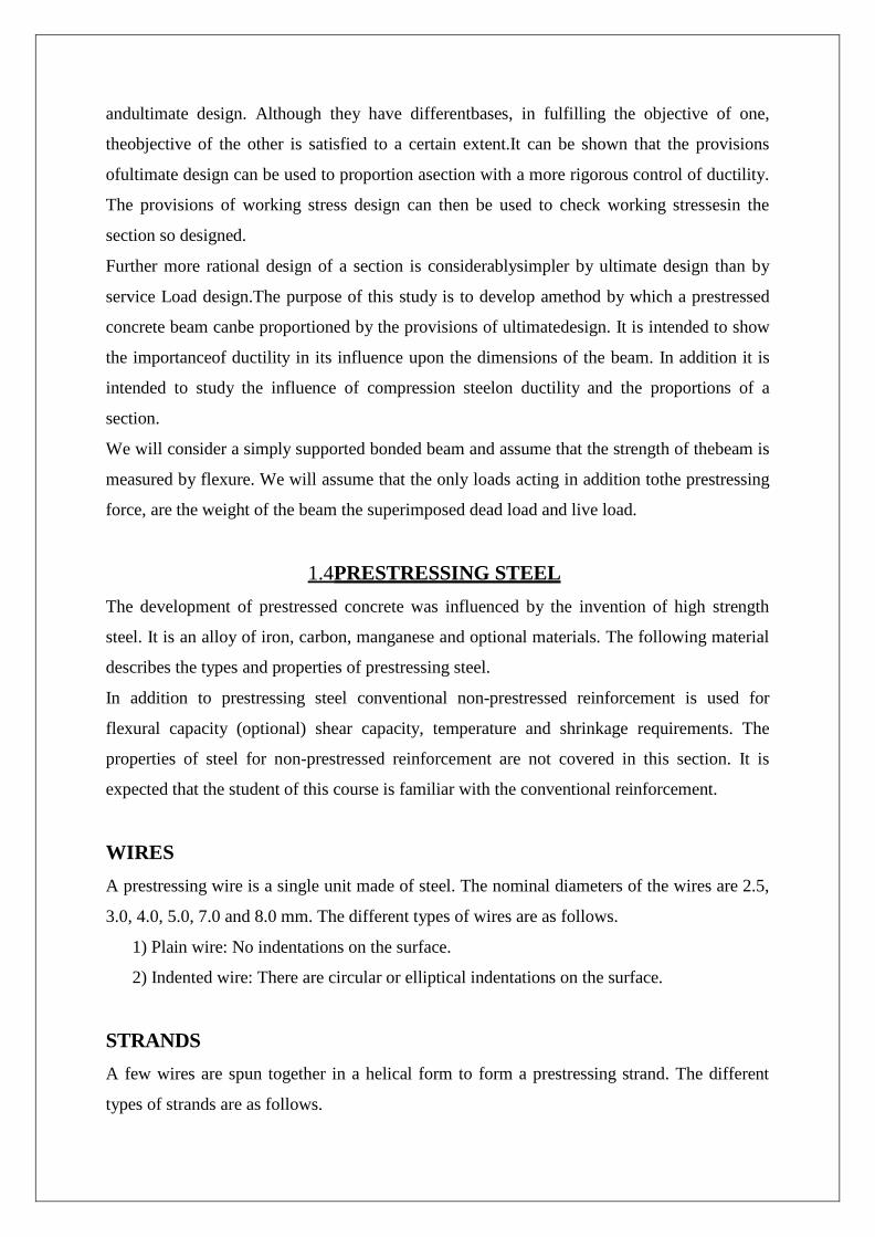
TENDONS A group of strands or wires are placed together to form a prestressing tendon. The tendons
are used in post-tensioned members. The following figure shows the cross section of a typical
tendon. The strands are placed in a duct which may be filled with grout after the post-
tensioning operation is completed.
CABLES
Figure 2 - Tendon
A group of tendons form a prestressing cable. The cables are used in bridges.
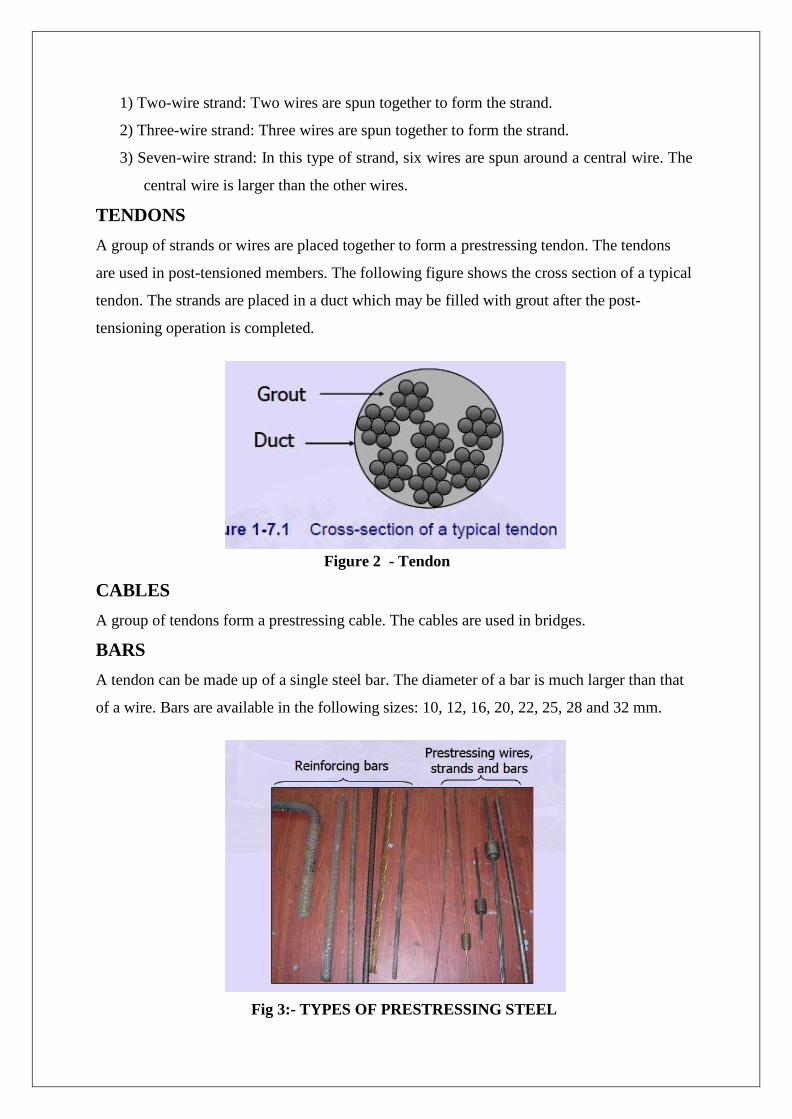
BARS A tendon can be made up of a single steel bar. The diameter of a bar is much larger than that
of a wire. Bars are available in the following sizes: 10, 12, 16, 20, 22, 25, 28 and 32 mm.
Fig 3:- TYPES OF PRESTRESSING STEEL
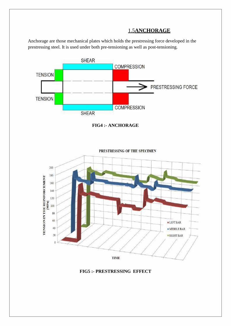
1.5ANCHORAGE
Anchorage are those mechanical plates which holds the prestressing force developed in the prestressing steel. It is used under both pre-tensioning as well as post-tensioning.
FIG4 :- ANCHORAGE
FIG5 :- PRESTRESSING EFFECT
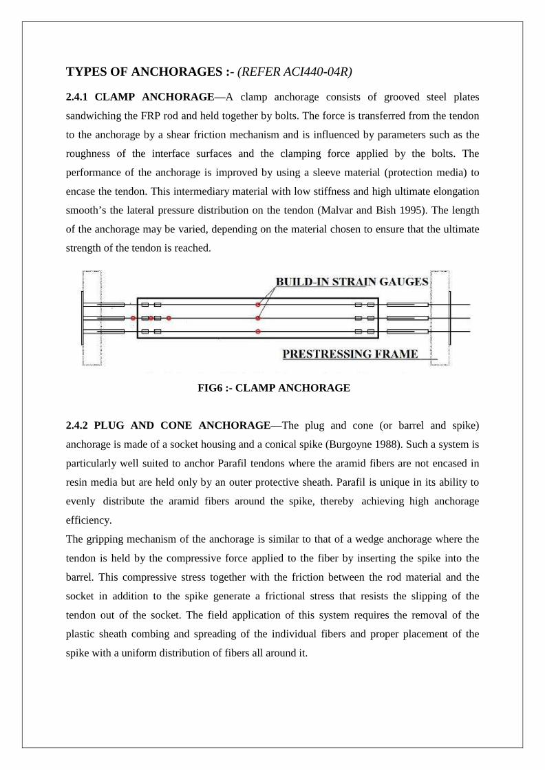
TYPES OF ANCHORAGES :- (REFER ACI440-04R)
2.4.1 CLAMP ANCHORAGE—A clamp anchorage consists of grooved steel plates
sandwiching the FRP rod and held together by bolts. The force is transferred from the tendon
to the anchorage by a shear friction mechanism and is influenced by parameters such as the
roughness of the interface surfaces and the clamping force applied by the bolts. The
performance of the anchorage is improved by using a sleeve material (protection media) to
encase the tendon. This intermediary material with low stiffness and high ultimate elongation
smooth’s the lateral pressure distribution on the tendon (Malvar and Bish 1995). The length
of the anchorage may be varied, depending on the material chosen to ensure that the ultimate
strength of the tendon is reached.
FIG6 :- CLAMP ANCHORAGE 2.4.2 PLUG AND CONE ANCHORAGE—The plug and cone (or barrel and spike)
anchorage is made of a socket housing and a conical spike (Burgoyne 1988). Such a system is
particularly well suited to anchor Parafil tendons where the aramid fibers are not encased in
resin media but are held only by an outer protective sheath. Parafil is unique in its ability to
evenly distribute the aramid fibers around the spike, thereby achieving high anchorage
efficiency.
The gripping mechanism of the anchorage is similar to that of a wedge anchorage where the
tendon is held by the compressive force applied to the fiber by inserting the spike into the
barrel. This compressive stress together with the friction between the rod material and the
socket in addition to the spike generate a frictional stress that resists the slipping of the
tendon out of the socket. The field application of this system requires the removal of the
plastic sheath combing and spreading of the individual fibers and proper placement of the
spike with a uniform distribution of fibers all around it.
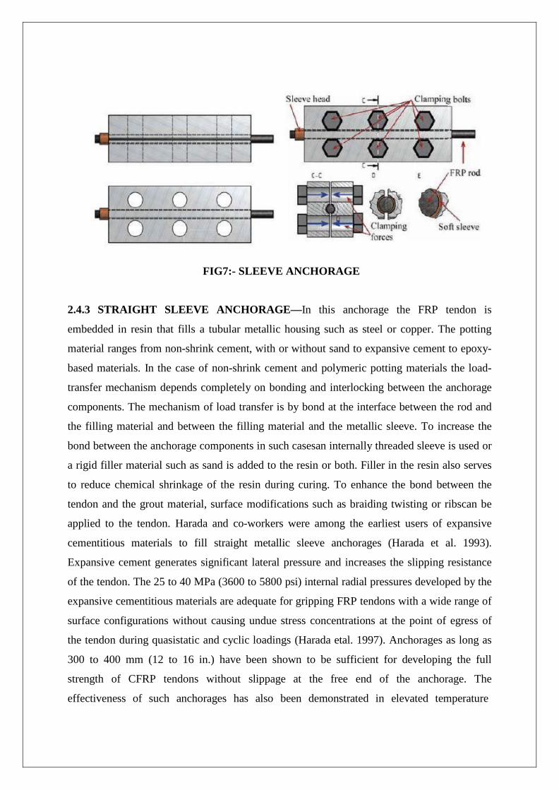
FIG7:- SLEEVE ANCHORAGE 2.4.3 STRAIGHT SLEEVE ANCHORAGE—In this anchorage the FRP tendon is
embedded in resin that fills a tubular metallic housing such as steel or copper. The potting
material ranges from non-shrink cement, with or without sand to expansive cement to epoxy-
based materials. In the case of non-shrink cement and polymeric potting materials the load-
transfer mechanism depends completely on bonding and interlocking between the anchorage
components. The mechanism of load transfer is by bond at the interface between the rod and
the filling material and between the filling material and the metallic sleeve. To increase the
bond between the anchorage components in such casesan internally threaded sleeve is used or
a rigid filler material such as sand is added to the resin or both. Filler in the resin also serves
to reduce chemical shrinkage of the resin during curing. To enhance the bond between the
tendon and the grout material, surface modifications such as braiding twisting or ribscan be
applied to the tendon. Harada and co-workers were among the earliest users of expansive
cementitious materials to fill straight metallic sleeve anchorages (Harada et al. 1993).
Expansive cement generates significant lateral pressure and increases the slipping resistance
of the tendon. The 25 to 40 MPa (3600 to 5800 psi) internal radial pressures developed by the
expansive cementitious materials are adequate for gripping FRP tendons with a wide range of
surface configurations without causing undue stress concentrations at the point of egress of
the tendon during quasistatic and cyclic loadings (Harada etal. 1997). Anchorages as long as
300 to 400 mm (12 to 16 in.) have been shown to be sufficient for developing the full
strength of CFRP tendons without slippage at the free end of the anchorage. The
effectiveness of such anchorages has also been demonstrated in elevated temperature
extended duration relaxation tests (Dye, Bakis, and Nanni 1998). At this time, the main
shortcoming of this type of anchorage appears to be the 2- to 3-day curing time for expansive
cementitious materials.
FIG8:- CONTOURED ANCHORAGE 2.4.4 CONTOURED SLEEVE ANCHORAGE- The contoured sleeve anchorage has the
same components as the straight sleeve anchorage. The principal difference between the two
systems is the varied profile of the inner surface of the contoured sleeve, which may be
linearly tapered or parabolically tapered.
The load transfer mechanism from the tendon to the sleeve is by interface shear stress, which
is a function of bonding, and radial stress produced by the variation of the potting material
profile. A conical profile with a constant taper angle is the most popular type of resin potted
anchorage. Kim and Meier (1991) developed a variable stiffness anchorage for CFRP
tendons. The work was based on concepts of a commercial anchorage developed by the Swiss
company BBR. The anchorage was made of a cone filled with an epoxy matrix containing
high-modulus ceramic filler. Holte Dolan, and Schmidt (1993) described a parabolic
anchorage with epoxy sand filler.The following parameters affect the performance of a
resinpotted anchorage length of the anchorage angle of theanchorage cone front radius of
anchorage cone modulus ofelasticity of the potted material, and length and
moduluscharacteristic of the “soft zone” in resin filler at the front ofthe anchorage. Potted
anchorages often fail through pullout of the tendon from the resin grout rather than by rupture
ofthe tendon. Practical drawbacks with this anchor includepre-cutting the tendons to length
and the curing time for thepotting material.
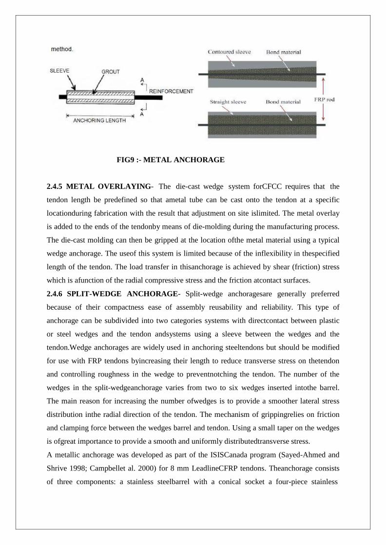
FIG9 :- METAL ANCHORAGE 2.4.5 METAL OVERLAYING- The die-cast wedge system forCFCC requires that the
tendon length be predefined so that ametal tube can be cast onto the tendon at a specific
locationduring fabrication with the result that adjustment on site islimited. The metal overlay
is added to the ends of the tendonby means of die-molding during the manufacturing process.
The die-cast molding can then be gripped at the location ofthe metal material using a typical
wedge anchorage. The useof this system is limited because of the inflexibility in thespecified
length of the tendon. The load transfer in thisanchorage is achieved by shear (friction) stress
which is afunction of the radial compressive stress and the friction atcontact surfaces.
2.4.6 SPLIT-WEDGE ANCHORAGE- Split-wedge anchoragesare generally preferred
because of their compactness ease of assembly reusability and reliability. This type of
anchorage can be subdivided into two categories systems with directcontact between plastic
or steel wedges and the tendon andsystems using a sleeve between the wedges and the
tendon.Wedge anchorages are widely used in anchoring steeltendons but should be modified
for use with FRP tendons byincreasing their length to reduce transverse stress on thetendon
and controlling roughness in the wedge to preventnotching the tendon. The number of the
wedges in the split-wedgeanchorage varies from two to six wedges inserted intothe barrel.
The main reason for increasing the number ofwedges is to provide a smoother lateral stress
distribution inthe radial direction of the tendon. The mechanism of grippingrelies on friction
and clamping force between the wedges barrel and tendon. Using a small taper on the wedges
is ofgreat importance to provide a smooth and uniformly distributedtransverse stress.
A metallic anchorage was developed as part of the ISISCanada program (Sayed-Ahmed and
Shrive 1998; Campbellet al. 2000) for 8 mm LeadlineCFRP tendons. Theanchorage consists
of three components: a stainless steelbarrel with a conical socket a four-piece stainless
steelconical wedge set and a thin soft metal sleeve that is placedbetween the wedges and the
tendon. The distinct feature ofthe anchorage is that the taper angle of the wedge is 0.1degrees
greater than that of the inner surface of the barrel.The difference in angle between the barrel
and the wedgeshelps to produce more desirable radial stress distribution onthe tendon and
ensures that failure of the tendon occursoutside the anchorage. An experimental and
analyticalinvestigation of this anchorage has been reported by Al-Mayah,Soudki, and
Plumtree (2001). Non-metallic versions of this anchorage in which the elements are made
either from ultra-high-performance concrete (UHPC), where the barrel is wrapped with CFRP
sheet or from carbon fiber reinforced reactive powder concrete have been developed
andtested by edaTaha and Shrive (2003a,b) and Shaheen(2004) respectively.
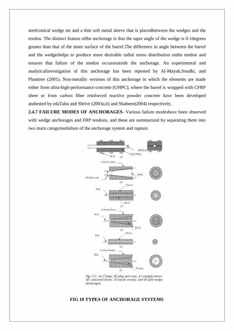
2.4.7 FAILURE MODES OF ANCHORAGES- Various failure modeshave been observed
with wedge anchorages and FRP tendons, and these are summarized by separating them into
two main categoriesfailure of the anchorage system and rupture.
FIG 10 TYPES OF ANCHORAGE SYSTEMS
Failure of the anchorage system This kind of failure can be classified into four modes:
1. Movement or slip of the tendon out of the anchorage caused by insufficient grip (low shear
force) between the tendon and sleeve-Grip can be increased by increasing thefriction at the
contact surfaces, by increasing the normalforce applied, or both.
2. Slip of the sleeve and tendon together relative to the wedges-This indicates a high shear
force between thetendon and sleeve together with a lower shear force betweenthe sleeve and
wedges. This can be overcome in the samemanner as mentioned in 1.
3. Slip of the wedges relative to barrel-This rarely happens, mainly because of the design and
geometrical configuration of the wedges and the barrel. It is often accompanied
by crushing of the tendon.
4. Rupture of the rod inside the anchorage-High stress concentrations can be generated in the
tendon inside the anchorage, causing damage of the fibers. An anchorage design that results
in low stress concentration and uniform load distribution in the anchor overcomes this
problem.
Failure of the tendon outside the anchorage-If the tendon does not break in or
within three diameters of the anchorage, then the anchorage is not contributing to the failure
of the tendon and is considered a satisfactory anchorage design.
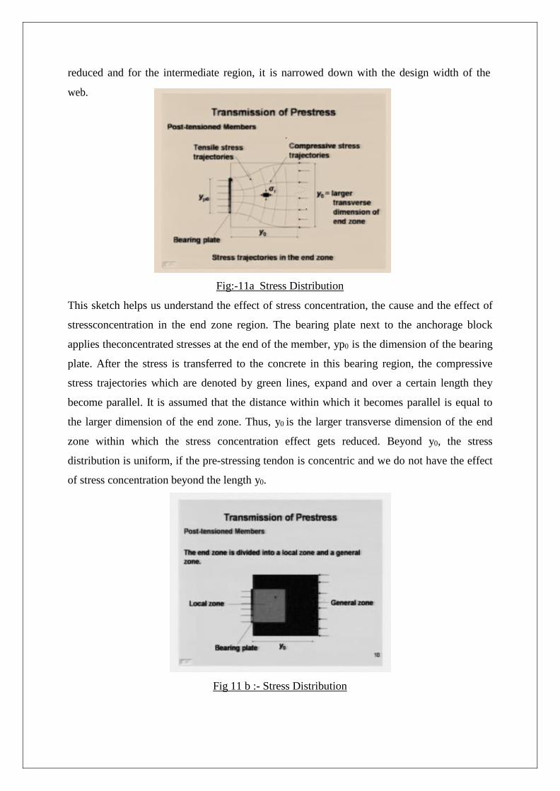
Stress Distribution in End Block-The end zone (or end block) of a post-tensioned
member is a flared region which is subjected to highstress from the bearing plate next to the
anchorage block. It needs special design of transversereinforcement. The design
considerations are bursting force and bearing stress. Unlike, in a pretensioned member, where
the prestress is transferred gradually, in a post-tensioned member, the stress is transferred at
the end. Hence, the end region of a post-tensioned member, which is called the end zone (or
the end block) is subjected to much higher stress concentration. To reduce the effect of stress
concentration for an I section, the end is made into a rectangular section by bearing the web,
so that the thickness at the end zone is much larger than the thickness of the web in the
intermediate region. Thus, the end zone of a post-tensioned member is usually a rectangular
section. This part of the rectangular section is carried over a certain distance within which
there is a high stress concentration. Beyond that end zone region, the width of the web is
reduced and for the intermediate region, it is narrowed down with the design width of the
web.
Fig:-11a Stress Distribution
This sketch helps us understand the effect of stress concentration, the cause and the effect of
stressconcentration in the end zone region. The bearing plate next to the anchorage block
applies theconcentrated stresses at the end of the member, yp0 is the dimension of the bearing
plate. After the stress is transferred to the concrete in this bearing region, the compressive
stress trajectories which are denoted by green lines, expand and over a certain length they
become parallel. It is assumed that the distance within which it becomes parallel is equal to
the larger dimension of the end zone. Thus, y0 is the larger transverse dimension of the end
zone within which the stress concentration effect gets reduced. Beyond y0, the stress
distribution is uniform, if the pre-stressing tendon is concentric and we do not have the effect
of stress concentration beyond the length y0.
Fig 11 b :- Stress Distribution
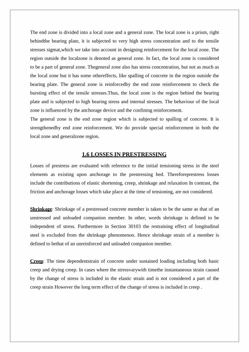
The end zone is divided into a local zone and a general zone. The local zone is a prism, right
behindthe bearing plate, it is subjected to very high stress concentration and to the tensile
stresses sigmat,which we take into account in designing reinforcement for the local zone. The
region outside the localzone is denoted as general zone. In fact, the local zone is considered
to be a part of general zone. Thegeneral zone also has stress concentration, but not as much as
the local zone but it has some othereffects, like spalling of concrete in the region outside the
bearing plate. The general zone is reinforcedby the end zone reinforcement to check the
bursting effect of the tensile stresses.Thus, the local zone is the region behind the bearing
plate and is subjected to high bearing stress and internal stresses. The behaviour of the local
zone is influenced by the anchorage device and the confining reinforcement.
The general zone is the end zone region which is subjected to spalling of concrete. It is
strengthenedby end zone reinforcement. We do provide special reinforcement in both the
local zone and generalzone region.
1.6 LOSSES IN PRESTRESSING
Losses of prestress are evaluated with reference to the initial tensioning stress in the steel
elements as existing upon anchorage to the prestressing bed. Thereforeprestress losses
include the contributions of elastic shortening, creep, shrinkage and relaxation In contrast, the
friction and anchorage losses which take place at the time of tensioning, are not considered.
Shrinkage: Shrinkage of a prestressed concrete member is taken to be the same as that of an
unstressed and unloaded companion member. In other, words shrinkage is defined to be
independent of stress. Furthermore in Section 30103 the restraining effect of longitudinal
steel is excluded from the shrinkage phenomenon. Hence shrinkage strain of a member is
defined to bethat of an unreinforced and unloaded companion member.
Creep: The time dependentstrain of concrete under sustained loading including both basic
creep and drying creep. In cases where the stressvarywith timethe instantaneous strain caused
by the change of stress is included in the elastic strain and is not considered a part of the
creep strain However the long term effect of the change of stress is included in creep .

Relaxation: The decrease of steel stress when subjected to a sustained strain Similar to the
creep strain the stress change which can be elastically calculated from the strain change is not
included in the relaxation. In other words relaxation is defined to be that portion of the
prestress loss which cannot be elastically related to the changes in strain so relaxation loss of
prestress is subdivided into two parts the initial relaxation loss occurring before transfer of
prestress and the long term relaxation loss occurring after transfer.

CHAPTER 2
FIBRE REINFORCED POLYMER FOR PRESTRESSING 2.1LITERATURE SURVEY
2.2 HISTORICAL DEVELOPMENT AND USE OF FRP
REINFORCEMENT
2.3 DESIGN GUIDELINES AND TECHNICAL COMMITTEES
2.4 RESEARCH EFFORTS
2.1 LITERATURE SURVEY
(REFER ACI440-04R) Fiber-reinforced polymer (FRP) composites have been proposed for use as prestressing
tendons in concrete structures. The promise of FRP materials lies in their high-strength
lightweight, noncorrosive, nonconducting, and nonmagnetic properties. In addition, FRP
manufacturing, using various cross-sectional shapes and material combinations, offers unique
opportunities for the development of shapes and forms that would be difficult or impossible
with conventional steel materials. Lighter-weight materials and preassembly of complex
shapes can boost constructibility and efficiency of construction.
At present the higher cost of FRP materials suggests that FRP use will be confined to
applications where the unique characteristics of the material are most appropriate.
Efficiencies in construction and reduction in fabrication costs will expand their potential
market. FRP reinforcement is available in the form of bars, grids, plates, and tendons. This
document examines both internal and external prestressed reinforcement in the form of
tendons.
One of the principal advantages of FRP tendons for prestressing is the ability to configure the
reinforcement to meet specific performance and design objectives. FRP tendons may be
configured as rods, bars, and strands as shown in Table. 1.1. The surface texture of FRP
tendons may vary resulting in bond with the surrounding concrete that varies from one tendon
configuration to another. Unlike conventional steel reinforcement there are no standardized
shapes, surface configurationsfiber orientation constituent materials and proportions for the
final products.
Similarly, there is no standardization of the methods of production, such as pultrusion,
braiding, filament winding, or FRP preparation for a specific application. Thus, FRP
materials require considerable engineering effort to use properly. Bakis (1993) has outlined
manufacturing processes. FRP tendons are typically made from one of three basic fibers.
These fibersareARAMID, CARBON, AND GLASS. Aramid fibers consist of a semi
crystalline polymer known as aromatic polyamide. Carbon fibers are based on the layered
graphene (hexagonal) networks present in graphite while glass generally uses either E-glass
or S-glass fibers. E-glass is a low-cost calcium-alumino-boro-silicate glass used where
strength, low conductivity, and acid resistance are important. S-glass is a magnesium-
alumino-silicate glass that has higher strength, stiffness, and ultimate strain than E-glass. S-

glass costs more than E-glass, and both are susceptible to degradation in alkaline
environments. Table 1.1 gives properties of typical fibers.
The selection of the fiber is primarily based on consideration of cost, strength, stiffness, and
long-term stability. Within these fiber groups different performance and material
characteristics may be achieved. For example aramids may come in low, high, and very high
modulus configurations. Carbon fibers are also available with moduli ranging from below
that of steel to several multiples of that of steel. Of the several fiber types glass-based FRP
reinforcement is least expensive and generally uses either E-glass or S-glass fibers. The resins
used for fiber impregnation are usually thermo setting and may be polyestervinylester epoxy
phenolic, or polyurethane.
The formulation, grade, and physical-chemical characteristics of resins are practically
limitless. The possible combinations of fibers, resins, additives, and fillers make
generalization of the properties of FRP tendons very difficult. Additionally FRP composites
are heterogeneous and anisotropic. Final characteristics of an FRP tendon are dependent on
fiber and resin properties, as well as the manufacturingprocess. Specific details of a particular
tendon should beobtained from the manufacturer of the tendon.
Table 1.1 Fiber Properties
2.2 HISTORICAL DEVELOPMENT AND USE OF FRP REINFORCEMENT
(REFER ACI440-04R)
The concept of using short glass fiber reinforcement in concrete was first introduced in the
1930s but was not developed into long fiber reinforcement for nearly two decades. In the
1950s and 1960s the U.S. Army Corps of Engineers was sufficiently interested in long glass
fibers for reinforcement that a series of comprehensive reports was compiled (Mather and
Tye 1955Pepper and Mather 1959; Wines, Dietz, and Hawley 1966). Although these reports
were generated research and site applications were limited. In the 1970s, corrosion-induced
deterioration of concrete structures, particularly bridge decks, led to a renewed interest in
designstrategies that would reduce susceptibility of structures to corrosive environments. In
the 1970s, research activities started in Germany on glass FRP-based prestressing tendons.
In 1978, a joint venture between German contractor Strabag-Bau and German chemical
producer Bayer resulted in glass fiberreinforced polymer (GFRP) tendons and an anchorage
system for post-tensioning applications. These tendons were incorporated in several bridges
in Germany and Austria. After various transition stages however, Strabag stopped its
activities in this field in the early 1990s. The National Bureau of Standards (NBS)now
renamed the National Institute of Standards and Technology (NIST) examined non-metallic
rods for antenna guy wires. In the process, theyconducted some of the first research into
anchorage of composite rods that became relevant to prestressed concrete application of FRP
materials (NBS 1976). Interest in the corrosion-resistant properties of non-metallic bars and
tendons continued to grow in the 1980s. In 1983, AKZO, a chemical producer in the
Netherlands, and HBG, a contractor, jointly developed aramid fiber reinforced polymer
(AFRP) prestressing tendons. The Japanese have also undertaken an extensive national
program to examine the use of FRP reinforcement in concrete structures. Around 1980,
research and development began in Japan on production techniques for FRP reinforcement
and its application to concrete structures.
This research and development originally focused on the development of FRP-reinforced
concrete members that used FRPs instead of steel reinforcing bars andprestressing tendons. In
the United States, a new anchorage was developed for glass fiber tendons (Iyer and
Kumarswamy 1988), and the prestressing use of Kevlar was investigated (Dolan 1989). Iyer’s
anchorage was supported financially by the Florida Department of Transportation (FDOT),
which funded a major study to investigate the prestressing application of glass fiber tendons
for bridge and marine substructures (Sen,Issa, and Mariscal 1992).
This research culminated in the first conference to focus on FRP composites for civil
engineering applications (Iyer and Sen 1991), and the construction of the first FRP
prestressed bridge in RapidCity, South Dakota (Iyer 1993). These similar efforts led to the
development of several commercial tendon systems, many of which are discussed in the
proceedings of the First International Symposium for FRP in Reinforced Concrete Structures
(FRPRCS-1) (Nanni and Dolan 1993), and in a Japanese Society of Civil Engineers
publication (JSCE 1996).
2.3DESIGN GUIDELINE AND TECHNICAL COMMITTEES
(REFER ACI440-04R) In 1993, the first design guidelines for FRP-reinforced and prestressed concrete buildings
were established by the Japanese Society of Civil Engineers. The Japanese version of the
guideline was released in 1995, while the English version (Sonobe et al. 1997) was published
in 1997. The Canadian Standards Association has produced two standards CAN/ CSA S6-00
and CAN/CSA S806-02 that contain code provisions for the use of FRP prestressing tendons
in bridges and buildings respectively. In Europe, unified design guidelines for FRP
reinforcement are under development. A task group with this aim was established at the end
of 1996, within the former CEB (Euro-International Concrete Committee). In December
1997, a 4-year training and mobility of researcher’s network project titled “Development of
Guidelines for the Design of Concrete Structures, Reinforced, Prestressed or Strengthened
with Advanced Composites,” started. This so called “ConFiber-Crete Network” was
comprised of 11 teams from nine different European countries. Since the merger of CEB and
FIP (Federation Internationalede la Precontrainte), this task group has been integrated in the
new fib(Federation Internationale du Béton). Task Group 9.3 of fibCommission 9 is charged
with developingdesign guidelines for concrete structures reinforced, prestressed, or
strengthened with FRP, based on the designformat of the CEB-FIP Model Code and
Eurocode 2 (fibTG9.3). Recent activities in Europe have been summarized by Matthys and
Taerwe (2001).
The American Society of Civil Engineers (ASCE) establisheda standards committee to
address standalone FRP products.The Transportation Research Board (TRB) has formally
established Committee A2C07 to examine the use of FRP in bridge structures. Other societies
including the Society for the Advancement of Material and Process Engineering (SAMPE)
and the Market Development Alliance (MDA) of the FRP Composites Industry have been
active in the area of FRP for construction use.
2.4RESEARCH EFFORTS
(REFER ACI440-04R) Early development work on prestressing with FRP was carried out at the South Dakota
School of Mines by Iyer who developed the first prestressing anchorage in the late 1980s.
The first glass fiberprestressed bridge built in the United States was in Rapid City, South
Dakota, in 1990. Other research was carried out at the University of South Florida, Florida
Atlantic University, and the Florida Department of Transportation (Sen, Issa, and Mariscal
1992).
Studies included static and fatigue testing of beams and half-scale bridges durability studies
and full-scale testing of piles. All three materials- aramid, carbon, and glass were evaluated.
Work relating to FRP prestressing in the United States has been documented by Dolan
(1999). Much of the research on FRP reinforcement in the United States has been conducted
by individual investigators at the University of Arizona(Eshani, Saadatmanesh and Nelson
1997), the University of Michigan (Naaman and Jeong 1995), the Massachusetts Institute of
Technology (Triantafillou and Deskovic 1991), Pennsylvania State University (Nanni et al.
1996a,b), South Dakota School of Mines (Iyer et al. 1996), the University of California (Long
Beach),
West Virginia University (Vijay and GangaRao 2001), the University of Wyoming (Dolan et
al. 2000), and Lawrence Technological University (Grace 2000a,b). In 1993 FHWA
sponsored research into acceleratedaging and standardized testing of FRP materials at
Georgia Institute of Technology, Pennsylvania State University, and the Catholic University
of America. In 1994, FHWA sponsored research into development of design
recommendations for FRP prestressing for bridge girders that led to design specification
recommendations for AASHTO (Dolan et al. 2000). Lawrence Technological University has
developed a demonstration bridge using external unbonded FRP tendons (Grace 1999). In
Canada, several researchers mostly within ISIS Canada (Canadian Network of Centers of
Excellence on Intelligent Sensing for Innovative Structures), have been investigating
applications of FRP prestressing tendons. Work at the University of Manitoba has
emphasized carbon FRP tendons and has considered the behavior of prestressed beams
underboth service and ultimate conditions (Abdelrahman, Tadros, and Rizkalla 1995; Fam,
Rizkalla, and Tadros 1997). Extensive studies on bond and transfer length have also been
conducted. At the Royal Military College of Canada (RMC), work has been done on aramid
FRP tendons (McKay and Erki 1993), and more recently on carbon FRP tendons.
Researchers at Queen’s University have been investigating the low temperature and long-
term behavior of beams prestressed with CFRP (Bryan and Green 1996). Additionally the
possibility of using CFRP rods to prestress bridge deck slabs was investigated (Braimah,
Green, and Soudki 1996), and work on the transfer length of beams prestressed with carbon
FRP was conducted (Soudki, Green, and Clapp 1997). Partially prestressed, partially bonded
FRP tendons have been investigated (Rizkalla, Fang, and Campbell 2001). Noncorrosive
wedge-type anchorages for FRP tendons have been developed at the University of Calgary
(Sayed-Ahmed and Shrive 1998; Campbell et al. 2000; Shaheen 2004). At the University of
Sherbrooke, extensive investigations are being conducted into the durability of FRP rods for
reinforcing and prestressing concrete, and into the development of a bond-type anchorage
(Zhang 2002).
The effects of temperature on beams prestressed with FRP tendons have been the focus of
research at Concordia University and applications of unbonded FRP tendons have been
considered at the University of Windsor (Salib, Abdel-Sayed, and Grace 1999). Researchers
at Carleton University and the University of Waterloo are also investigating applications of
FRP prestressing tendons. The decline in the Japanese economy in the 1990s slowed the
Japanese development program and has curtailed the availability of many Japanese products
for evaluation and testing in North America.
Developments in Japan have been addressed by Fukuyama (1999), and details of some recent
projects are available from the Advanced Composites Cables(ACC) Club. Activities in
Europe relating to the use of FRP have been reported by Taerwe and Matthys (1999). Of the
projects financially supported by the European community, the BRITE/EURAM project,
“Fiber Composite Elements and Techniques as Non-Metallic Reinforcement for Concrete,”
started November 1991 and ended in 1996. The Universities of Braunschweig and Ghent
together with industrial partners from Germany and The Netherlands, investigated
performance characteristics and structural aspects of FRP reinforcement for prestressed and
reinforced concrete members.
The EUROCRETE project, a Pan-European collaborative research program with partners
from the United Kingdom, the Netherlands, Switzerland, France, and Norway, began in
December 1993 and ended in 1997. This project included material development, research on
durability in aggressive environments, determination of structural behaviour, and
development of design guidance, techno-economic, and feasibility studies. The project
included construction of demonstration structures.
CHAPTER 3
DESIGN CRITERIA
3.1 DESIGN OF PRESTRESS BEAM
3.1.1) USING STEEL.
3.1.2) USING CFRP.
3.2 CALCULATION OF LOSSES
3.2.1) FOR STEEL.
3.2.2) FOR CFRP.
3.3 ANCHORAGE DESIGN
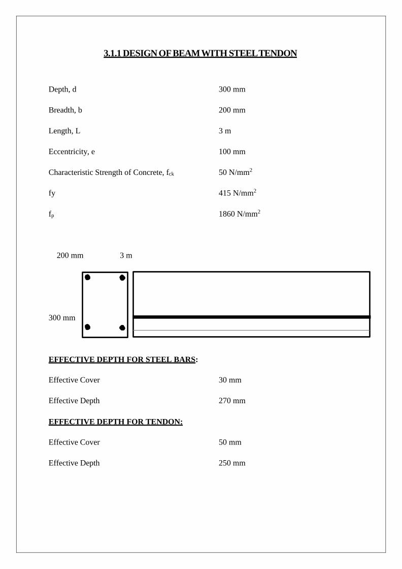
3.1.1 DESIGN OF BEAM WITH STEEL TENDON Depth, d 300 mm
Breadth, b 200 mm
Length, L 3 m
Eccentricity, e 100 mm
Characteristic Strength of Concrete, fck 50 N/mm2
fy 415 N/mm2
fp 1860 N/mm2
200 mm 3 m
300 mm EFFECTIVE DEPTH FOR STEEL BARS:
Effective Cover 30 mm
Effective Depth 270 mm
EFFECTIVE DEPTH FOR TENDON:
Effective Cover 50 mm
Effective Depth 250 mm
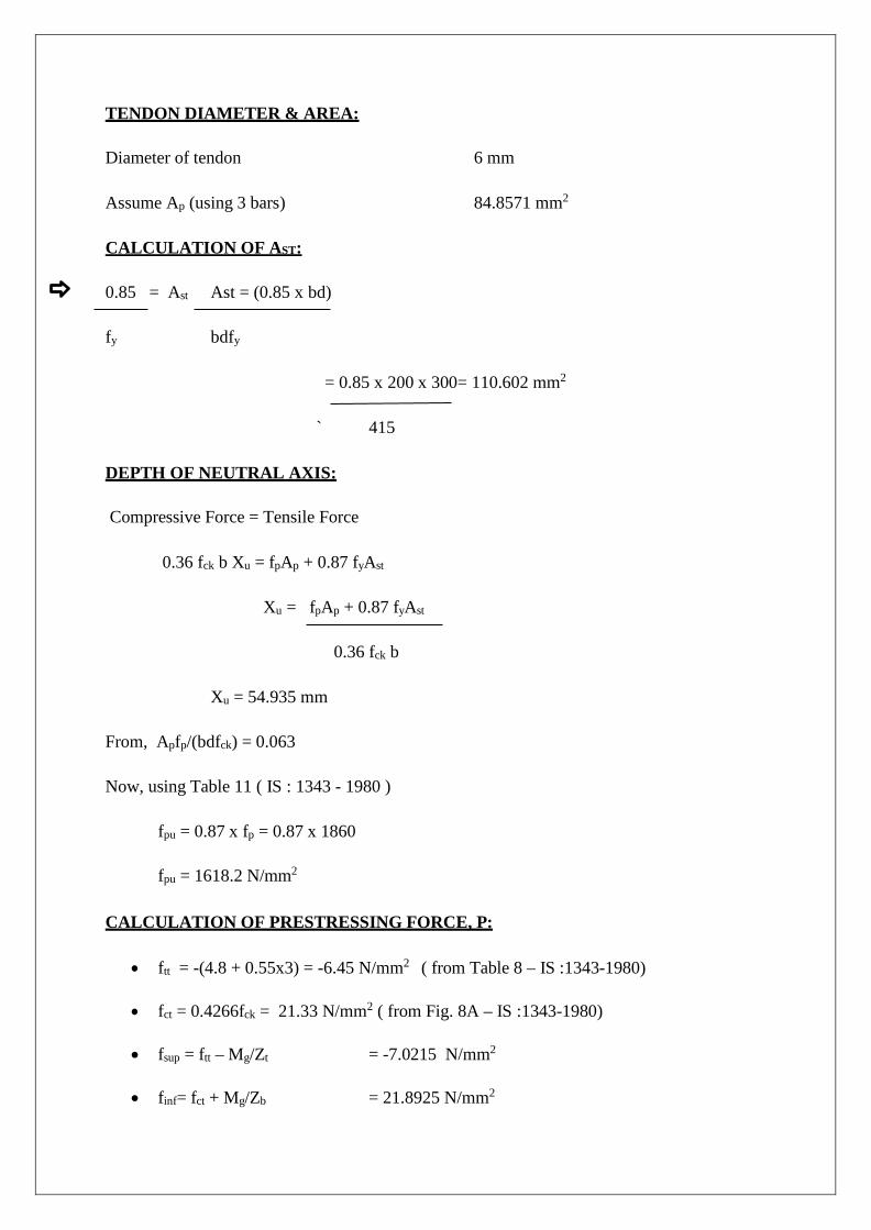
TENDON DIAMETER & AREA:
Diameter of tendon 6 mm
Assume Ap (using 3 bars) 84.8571 mm2
CALCULATION OF AST:
0.85 = Ast Ast = (0.85 x bd)
fy bdfy
= 0.85 x 200 x 300= 110.602 mm2
` 415
DEPTH OF NEUTRAL AXIS:
Compressive Force = Tensile Force
0.36 fck b Xu = fpAp + 0.87 fyAst
Xu = fpAp + 0.87 fyAst
0.36 fck b
Xu = 54.935 mm
From, Apfp/(bdfck) = 0.063
Now, using Table 11 ( IS : 1343 - 1980 )
fpu = 0.87 x fp = 0.87 x 1860
fpu = 1618.2 N/mm2
CALCULATION OF PRESTRESSING FORCE, P:
• ftt = -(4.8 + 0.55x3) = -6.45 N/mm2 ( from Table 8 – IS :1343-1980)
• fct = 0.4266fck = 21.33 N/mm2 ( from Fig. 8A – IS :1343-1980)
• fsup = ftt – Mg/Zt = -7.0215 N/mm2
• finf= fct + Mg/Zb = 21.8925 N/mm2
• P = A (finfZb + fsupZt) = 446.128 KN
(Zb + Zt )
• e = Z (finf – fsup) = 97.216 mm
A (finf + fsup)
MOMENT CALCULATION:
• MOMENT DUE TO DEAD LOAD:
wg = 24 x 0.2 x 0.3 = 1.5 KN/m
Mg = wg L2/8 = 1.6875KNm
• MOMENT DUE TO TENDON:
M1 = fpuAp( d – 0.42 Xu ) = 31.16 KNm
• MOMENT DUE TO AST:
M2 = 0.87 fyAst( d - 0.42 Xu) = 9.86 KNm
• TOTAL MOMENT OF RESISTANCE:
MR = M1 + M2 = 41.012 KNm
• CALCULATION OF LOAD:
Equating, MR = Mg + ML where, ML=
wuL/3 wu = 39.33 KN
Safe Load, w = wu /1.5
= 26.22 KN
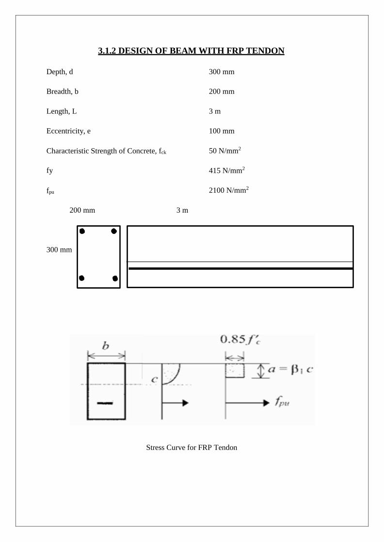
3.1.2 DESIGN OF BEAM WITH FRP TENDON
Depth, d 300 mm
Breadth, b
200 mm
Length, L
3 m
Eccentricity, e
100 mm
Characteristic Strength of Concrete, fck
fy
fpu
50 N/mm2
415 N/mm2
2100 N/mm2
200 mm 3 m
300 mm
Stress Curve for FRP Tendon
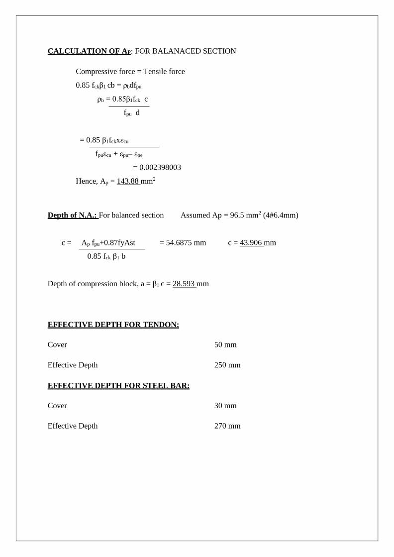
CALCULATION OF AP: FOR BALANACED SECTION
Compressive force = Tensile force
0.85 fckβ1 cb = ρbdfpu
ρb = 0.85β1fck c
fpu d
= 0.85 β1fckxεcu
fpuεcu + εpu– εpe
= 0.002398003
Hence, Ap = 143.88 mm2
Depth of N.A.: For balanced section Assumed Ap = 96.5 mm2 (4#6.4mm)
c = Ap fpu+0.87fyAst = 54.6875 mm c = 43.906 mm
0.85 fck β1 b Depth of compression block, a = β1 c = 28.593 mm
EFFECTIVE DEPTH FOR TENDON: Cover 50 mm
Effective Depth 250 mm
EFFECTIVE DEPTH FOR STEEL BAR:
Cover 30 mm
Effective Depth 270 mm
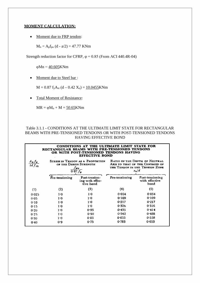
MOMENT CALCULATION:
• Moment due to FRP tendon:
Mn = Apfpu (d - a/2) = 47.77 KNm
Strength reduction factor for CFRP, φ = 0.85 (From ACI 440.4R-04)
φMn = 40.605KNm
• Moment due to Steel bar :
M = 0.87 fyAst (d – 0.42 Xu) = 10.0455KNm
• Total Moment of Resistance:
MR = φMn + M = 50.65KNm
Table 3.1.1 - CONDITIONS AT THE ULTIMATE LIMIT STATE FOR RECTANGULAR BEAMS WITH PRE-TENSIONED TENDONS OR WITH POST-TENSIONED TENDONS
HAVING EFFECTIVE BOND
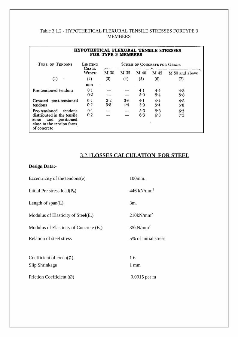
Table 3.1.2 - HYPOTHETICAL FLEXURAL TENSILE STRESSES FORTYPE 3 MEMBERS
3.2.1LOSSES CALCULATION FOR STEEL
Design Data:- Eccentricity of the tendons(e) 100mm.
Initial Pre stress load(Po) 446 kN/mm2
Length of span(L) 3m.
Modulus of Elasticity of Steel(Es) 210kN/mm2
Modulus of Elasticity of Concrete (Ec) 35kN/mm2
Relation of steel stress 5% of initial stress
Coefficient of creep(∅) 1.6 Slip Shrinkage 1 mm
Friction Coefficient (Ø) 0.0015 per m
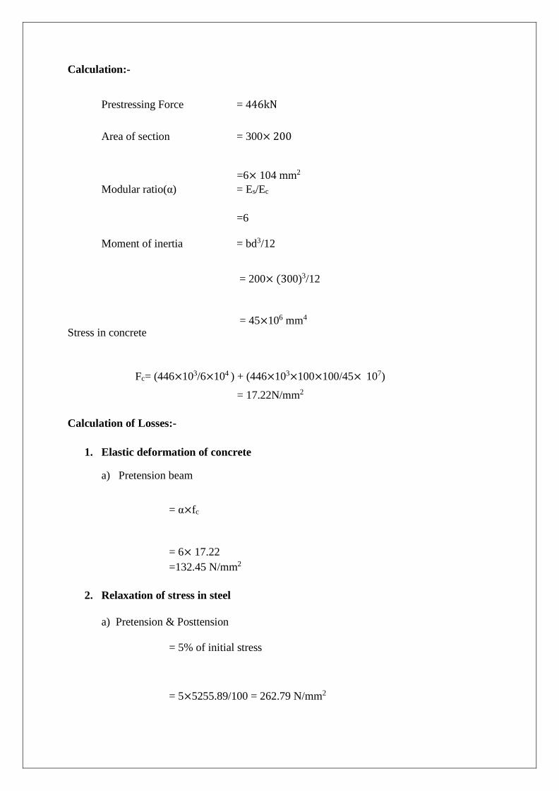
Calculation:-
Prestressing Force = 446kN
Area of section = 300× 200
=6× 104 mm2
Modular ratio(α) = Es/Ec
=6
Moment of inertia = bd3/12
= 200× (300)3/12
= 45×106 mm4 Stress in concrete
Fc= (446×103/6×104 ) + (446×103×100×100/45× 107) = 17.22N/mm2
Calculation of Losses:-
1. Elastic deformation of concrete
a) Pretension beam
= α×fc
= 6× 17.22 =132.45 N/mm2
2. Relaxation of stress in steel
a) Pretension & Posttension
= 5% of initial stress
= 5×5255.89/100 = 262.79 N/mm2
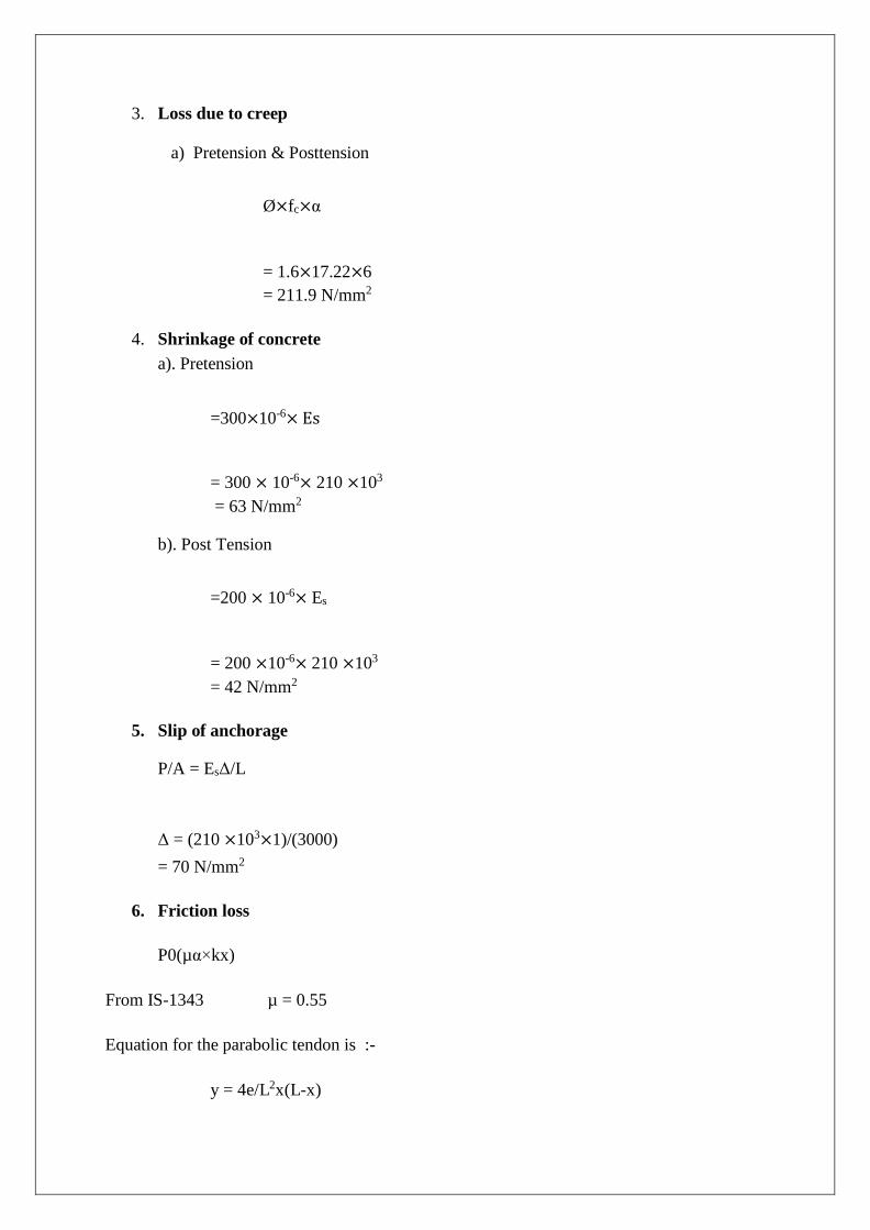
3. Loss due to creep
a) Pretension & Posttension
Ø×fc×α
= 1.6×17.22×6 = 211.9 N/mm2
4. Shrinkage of concrete
a). Pretension
=300×10-6× Es
= 300 × 10-6× 210 ×103
= 63 N/mm2
b). Post Tension
=200 × 10-6× Es
= 200 ×10-6× 210 ×103
= 42 N/mm2
5. Slip of anchorage
P/A = EsΔ/L
Δ = (210 ×103×1)/(3000) = 70 N/mm2
6. Friction loss
P0(µα×kx)
From IS-1343 µ = 0.55
Equation for the parabolic tendon is :-
y = 4e/L2x(L-x)
α= dy/dx
α= 4e/L (Calculating on starting point, x=0)
α = 0.133
µα = .055× .133 = 7.33× 10 -3
Kx= 0.0015 × 10 = 0.015
Loss due to friction = 1000 (7.33× 10⁻³ +0.015) = 54.2 N/mm2
Total loss in Pretension beam:
= ES+RS+CR+SR
= 133.8+262.7+214.08+63
= 673.58 N/mm2
Percentage loss =673.58×100/5255.89 = 12.75%
Total Loss due to Posttension beam
= RS+CR+SR+SA+FR
= 262.79+214.08+42+70+54.2
=642.98 N/mm2
Percentage Loss = 642.98× 100/5255.89 = 12.19%
3.2.2 LOSS OF PRESTRESS IN CFRP
Design Data :- Eccentricity of the tendons(e) 100mm.
Initial Pre stress load(Po) 446 kN/mm2
Length of span(L) 3m.
Modulus of Elasticity of Steel(Es) 210kN/mm2
Modulus of Elasticity of Concrete (Ec) 35kN/mm2
Relation of steel stress 5% of initial stress
Coefficient of creep(∅) 1.6 Slip Shrinkage 1 mm
Friction Coefficient(Ø) 0.0015 per m
Moment due to dead load 71.7 Nm
Calculation :-
Prestressing Force = 446 KN Area of section = 300× 200
=6× 104 mm2
Modular ratio(α) = Es/Ec =6
Moment of inertia = bd3/12
= 200× (300)3/12
= 45×106 mm4 Stress in concrete
Fc=(446×103/6×104 ) + (446×103×100×100/45× 107)-(71.7*100/6*104) = 17.344N/mm2
Calculation of Losses:-
1. Elastic deformation of concrete
a) Pretension beam
= α×fc
= 6×17.34 =67.30 N/mm2
2. Relaxation of stress in steel
a) Pretension & Posttension
= 3% of ultimate tensile strength of tendon
= .03×5255.89 = 157.67N/mm2
3. Loss due to creep
a) Pretension & Posttension
Ø×fc×α
= 1.6×17.34×6 = 134.61 N/mm2
4. Shrinkage of concrete
a). Pretension
=300×10-6× Es
= 300 × 10-6× 137.2×103
= 82 N/mm2
b). Post Tension
=200 × 10-6× Es
= 200 ×10-6× 137.2×103
= 76 N/mm2
5. Slip of anchorage
P/A = EsΔ/L
Δ = (137.2×103×1)/(3000) = 45.73 N/mm2
6. Friction loss
P0(µα×kx)
From IS-1343 µ = 0.55
Equation for the parabolic tendon is :-
y = 4e/L2x(L-x)
α= dy/dx
α= 4e/L (Calculating on starting point, x=0)
α = 0.133
µα = .055× .133 = 7.33× 10 -3
Kx= 0.0015 × 10 = 0.015
Loss due to friction = 1000 (7.33× 10⁻³ +0.015) = 5.42 N/mm2
Total loss in Pretension beam :
= ES+RS+CR+SR
= 157.67+67.3+134.61+82
= 441.58 N/mm2
Percentage loss =441.58×100/5255.89 = 8.401 %
Total Loss due to Posttension beam
= RS+CR+SR+SA+FR
= 157.67+67.3+134.61+82+45.733+54.2
=492.733 N/mm2
Percentage Loss = 492.733× 100/5255.89 = 10.31%
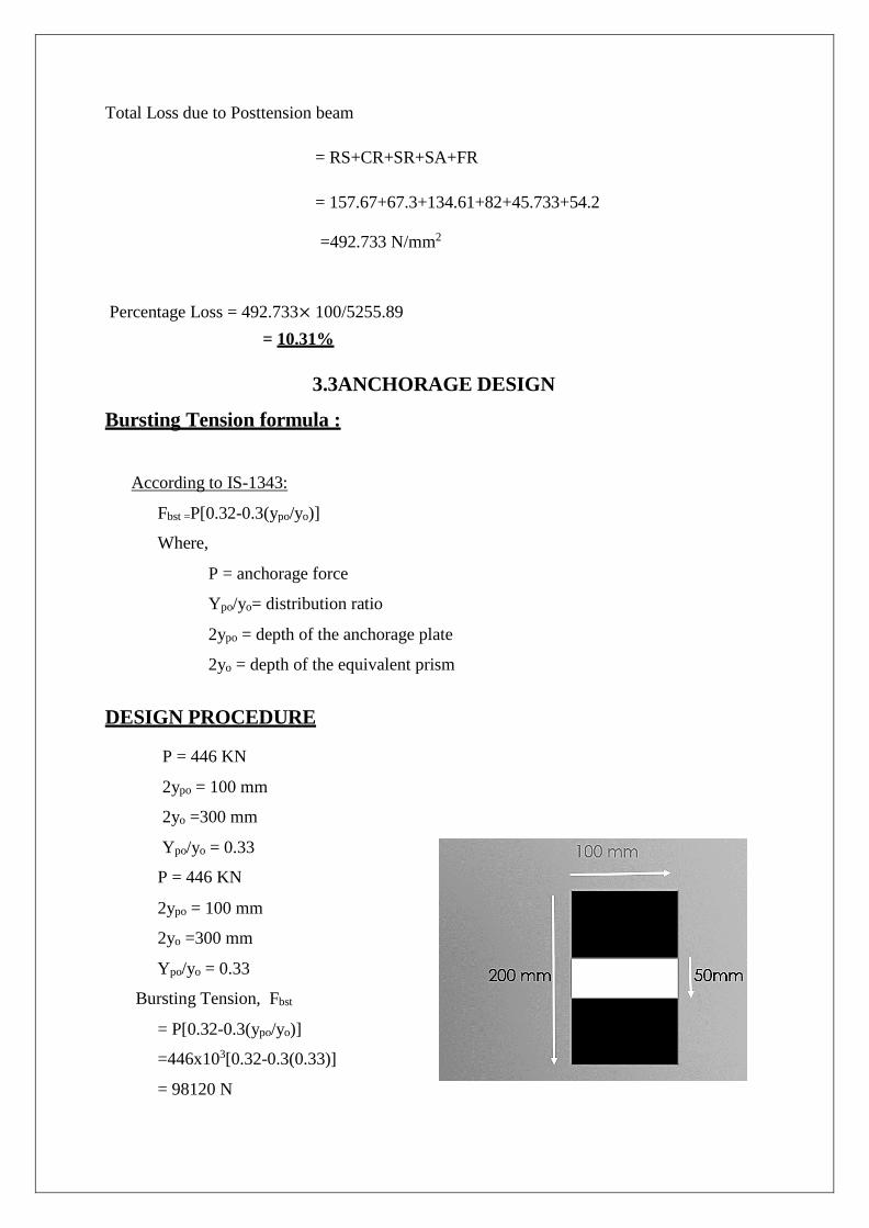
3.3ANCHORAGE DESIGN
Bursting Tension formula :
According to IS-1343:
Fbst =P[0.32-0.3(ypo/yo)]
Where,
P = anchorage force
Ypo/yo= distribution ratio
2ypo = depth of the anchorage plate
2yo = depth of the equivalent prism DESIGN PROCEDURE
P = 446 KN
2ypo = 100 mm
2yo =300 mm
Ypo/yo = 0.33
P = 446 KN
2ypo = 100 mm
2yo =300 mm
Ypo/yo = 0.33
Bursting Tension, Fbst
= P[0.32-0.3(ypo/yo)] =446x103[0.32-0.3(0.33)]
= 98120 N
CHAPTER 4
ANALYSIS RESULTS FROM ANSYS
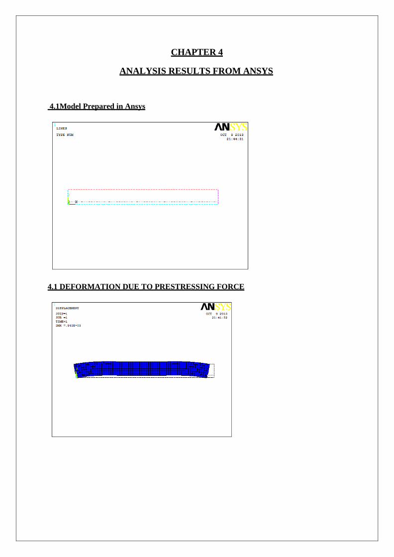
4.1Model Prepared in Ansys
4.1 DEFORMATION DUE TO PRESTRESSING FORCE
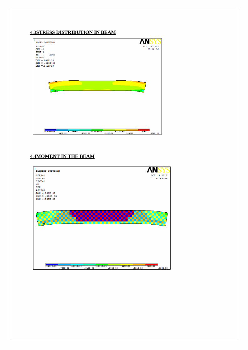
4.3STRESS DISTRIBUTION IN BEAM
4.4MOMENT IN THE BEAM
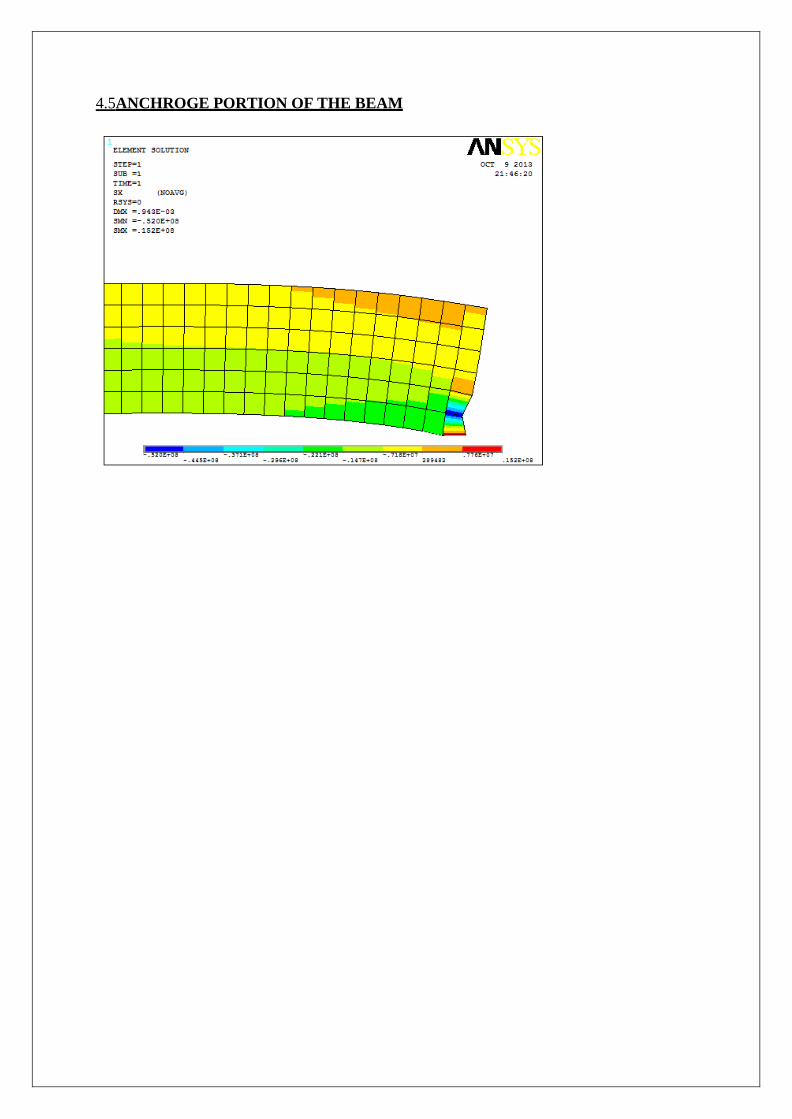
4.5ANCHROGE PORTION OF THE BEAM
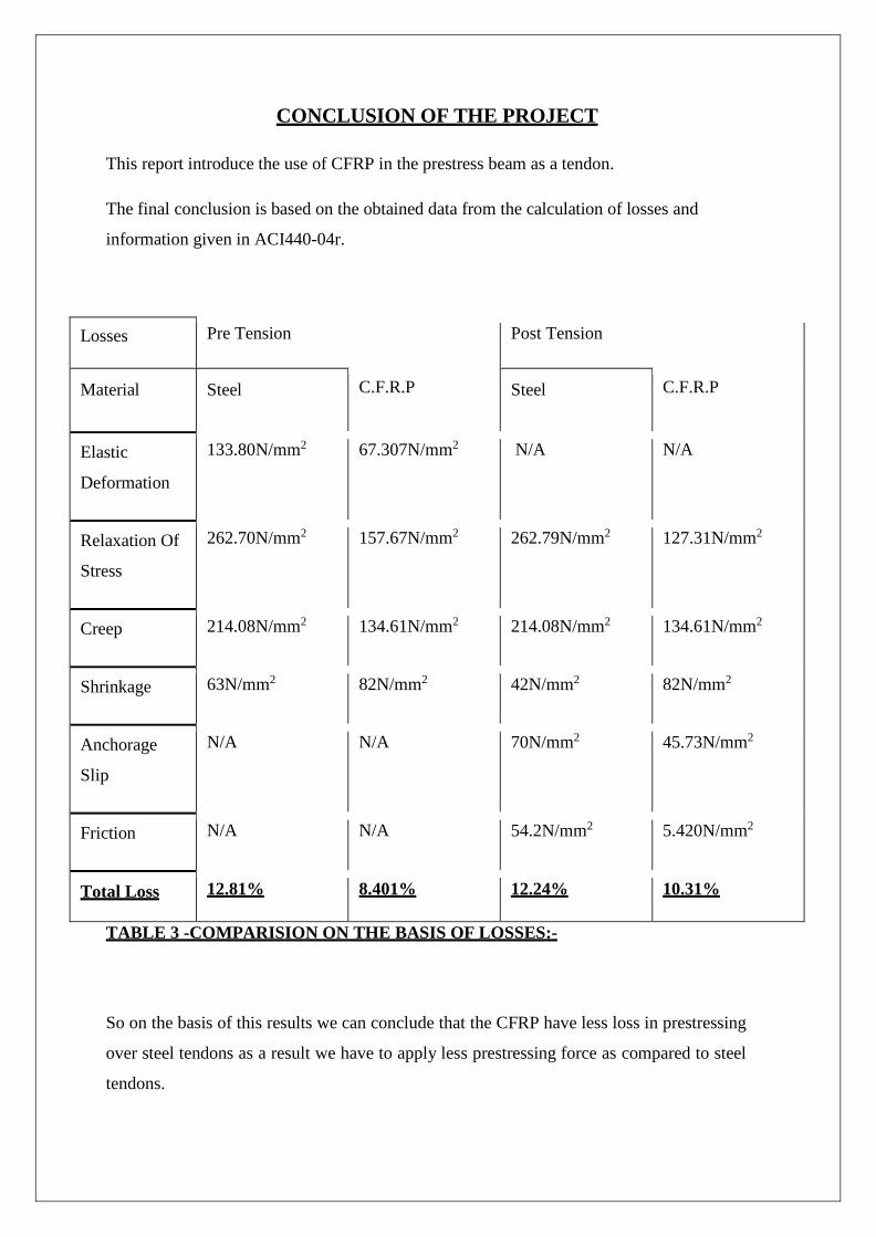
CONCLUSION OF THE PROJECT
This report introduce the use of CFRP in the prestress beam as a tendon.
The final conclusion is based on the obtained data from the calculation of losses and
information given in ACI440-04r.
Losses Pre Tension Post Tension
Material Steel C.F.R.P Steel C.F.R.P
Elastic
Deformation
133.80N/mm2 67.307N/mm2 N/A N/A
Relaxation Of
Stress
262.70N/mm2 157.67N/mm2 262.79N/mm2 127.31N/mm2
Creep 214.08N/mm2 134.61N/mm2 214.08N/mm2 134.61N/mm2
Shrinkage 63N/mm2 82N/mm2 42N/mm2 82N/mm2
Anchorage
Slip
N/A N/A 70N/mm2 45.73N/mm2
Friction N/A N/A 54.2N/mm2 5.420N/mm2
Total Loss 12.81% 8.401% 12.24% 10.31%
TABLE 3 -COMPARISION ON THE BASIS OF LOSSES:-
So on the basis of this results we can conclude that the CFRP have less loss in prestressing
over steel tendons as a result we have to apply less prestressing force as compared to steel
tendons.
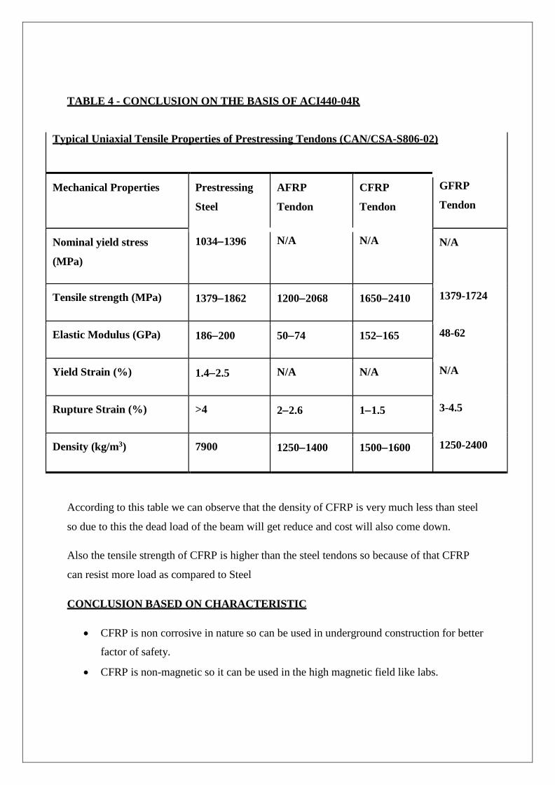
TABLE 4 - CONCLUSION ON THE BASIS OF ACI440-04R
Typical Uniaxial Tensile Properties of Prestressing Tendons (CAN/CSA-S806-02)
Mechanical Properties Prestressing
Steel
AFRP
Tendon
CFRP
Tendon
GFRP
Tendon
Nominal yield stress
(MPa)
1034−1396 N/A N/A N/A
Tensile strength (MPa) 1379−1862 1200−2068 1650−2410 1379-1724
Elastic Modulus (GPa) 186−200 50−74 152−165 48-62
Yield Strain (%) 1.4−2.5 N/A N/A N/A
Rupture Strain (%) >4 2−2.6 1−1.5 3-4.5
Density (kg/m3) 7900 1250−1400 1500−1600 1250-2400
According to this table we can observe that the density of CFRP is very much less than steel
so due to this the dead load of the beam will get reduce and cost will also come down.
Also the tensile strength of CFRP is higher than the steel tendons so because of that CFRP
can resist more load as compared to Steel
CONCLUSION BASED ON CHARACTERISTIC
• CFRP is non corrosive in nature so can be used in underground construction for better
factor of safety.
• CFRP is non-magnetic so it can be used in the high magnetic field like labs.
REFERENCES:-
1. ACI 440-04r (For Designing FRP Tendons)
2. ACI 440-06r(For FRP Properties)
3. ACI 440-01r (For FRP Anchaorage)
4. IS: 1343-1980 (For Prestressing Steel)
5. FRP tendon anchorage in post-tensioned concrete structures
J.W. Schmidt & B. TäljstenTechnical University of Denmark, Kgs. Lyngby, Denmark
A. BennitzLuleå University of Technology, Luleå, Sweden
J.W. Schmidt & H. PedersenCOWI A/S, Lyngby, Denmark
6. Prestress losses tihuang
7. Prestress Concrete by N.KrishnaRaju (For Design Procedure).
8. Anchoring Method For Prestressing Of FRP reinforcement
D Ďurech, Brno University of Technology, Czech Republic
F Girgle, Brno University of Technology, Czech Republic
D Horák, Brno University of Technology, Czech Republic
I Laníkovcá, Brno University of Technology, Czech Republic
P Štěpánek*, Brno University of Technology, Czech Republic
9. Design Recommendations For Concrete Structures Pre-stressed With FRP
Tendons,Final Report August 1, 2001 Prepared by University of Wyoming Charles W.
Dolan H.R. Hamilton III Pennsylvania State University Charles E. Bakis And
University of Missouri - Rolla Antonio Nanni
10. Google and Wikipedia (For Graphs and Images).