Embed Size (px)
Citation preview

http://www.iaeme.com/IJEET/index.asp 25 [email protected]
International Journal of Electrical Engineering & Technology (IJEET)
Volume 7, Issue 3, May–June, 2016, pp.25–39, Article ID: IJEET_07_03_003
Available online at
http://www.iaeme.com/ijeet/issues.asp?JType=IJEET&VType=7&IType=3
ISSN Print: 0976-6545 and ISSN Online: 0976-6553
Journal Impact Factor (2016): 8.1891 (Calculated by GISI) www.jifactor.com
© IAEME Publication
ANALYSIS OF VARIOUS COMPENSATION
DEVICES FOR POWER QUALITY
IMPROVEMENT IN WIND ENERGY
SYSTEM
M. Thirupathaiah and P. Venkata Prasad
Department of EEE, Chaitanya Bharathi Institute of Technology,
Gandipet, Hyderabad, India
V. Ganesh
Department of EEE, JNTUA College of Engineering,
Pulivendula, Y.S.R District, Andhra Pradesh, India
ABSTARCT
In recent trend, the renewable source of energy is increasingly used in the
electric power generation, which leads to certain power quality issues. Hence
some of the supplementary devices like capacitors, compensators or reactive
power injection devices are added to the compensation system. With the
advancement in power electronics, compensating devices such as Distribution
Static Compensator (DSTATCOM), Unified Power Quality Conditioner
(UPQC), Dynamic Voltage Restorer (DVR), Static Var Compensator (SVC)
etc. are used. In this paper, the characteristics of three important
compensating devices DVR, UPQC and DSTATCOM are analysed. Initially
these devices are modelled and their performance is analysed with common
power quality problems such as voltage sag, swell and harmonics. The overall
outcome suggests that the performance of the DSTATCOM is comparatively
better than that of the other two devices, which become the most suitable
device for power quality improvement in wind energy system.
Key words: Distribution Static Compensator (DSTATCOM), Dynamic
Voltage Restorer (DVR), Power Quality, Unified Power Quality Conditioner
(UPQC), Wind Energy System.
Cite this Article: M. Thirupathaiah, P. Venkata Prasad and V. Ganesh,
Analysis of Various Compensation Devices For Power Quality Improvement
In Wind Energy System. International Journal of Electrical Engineering &
Technology, 7(3), 2016, pp. 25–39
http://www.iaeme.com/ijeet/issues.asp?JType=IJEET&VType=7&IType=3

M. Thirupathaiah, P. Venkata Prasad and V. Ganesh
http://www.iaeme.com/IJEET/index.asp 26 [email protected]
1. INTRODUCTION
Today’s technological world completely depends on electricity; however the
availability of electric sources are low. The deficiency of electricity becomes the
breaking point for developing countries like India. Hence the electric utilities are
finding a suitable solution for providing uninterruptable electricity. In this situation
the usage of renewable energy sources are the better solution, so these renewable
energy sources are encouraged for electricity production [1, 2]. In India, the most
available renewable source is wind and solar and the research on this area is under
progress [3, 4]. The wind based energy acquisition is most encouraging research area
because of its low complexity in installation and maintenance. In wind energy
acquisition the wind turbine is used [5]. The technical challenges that a power system
integrated with a wind power requires the analysis of power quality issues such as
voltage regulation and stability [6, 7]. The wind turbine produces a continuous
variable output. In wind power system, the wind turbine has a great importance to the
power quality issues in the power system [8, 9]. The variations in the power output
are caused due to wind groom and the disturbances in the power system [10].
Therefore, the system has to manage such variations so that the power quality issues
such as voltage sag, voltage swell, flickers and harmonics can be considered w.r.to the
generation, transmission and distribution systems of wind power [11].
But, the wind generation produces turbulence into the network. An induction
generator directly connected to the grid system can be used to run a wind generation
system [12]. Due to the variations in the wind, the active power generated by an
induction generator varies which affects the reactive power absorbed by the induction
generator and its terminal voltage [13]. In order to provide the control over the active
power produced by the induction generator, the wind generation system should work
with a précised control technique [14]. At point of common coupling (PCC), a
compensator device such as Distribution Static Compensator (DSTATCOM), Unified
Power Quality Conditioner (UPQC), Dynamic Voltage Restorer (DVR) & Static Var
Compensator (SVC) etc. can be connected for improving the power quality which can
manage the challenges of wind turbines [15].
2. POWER QUALITY ISSUES IN WIND ENERGY SYSTEM
The guidelines for measurement of power quality of wind turbine are developed by
The International Electro-technical Commission (IEC) in coordination with the
Technical Committee-88.This commission explained the methodologies for
measuring the power quality characteristics of a wind turbine [16]. For grid
connection, the base for the analysis is provided by the data sheet with electrical
characteristic of wind turbine.
2.1. Power Quality Issues
2.1.1. Voltage Variations
In wind generation system, the velocity of wind and the torque developed by the
generator results in the variations in the voltage. This voltage variation results in real
and reactive power variations. The fluctuations in the wind power occur during the
normal operation of the wind turbine. The magnitude of these fluctuations depends on the impedance, phase angle, power factor of wind turbine and the strength of the grid.
Various types of voltage variations are given as follows:

Analysis of Various Compensation Devices For Power Quality Improvement In Wind Energy
System
http://www.iaeme.com/IJEET/index.asp 27 [email protected]
Voltage sag.
Voltage swells.
Voltage flicker.
Short interruptions.
Long duration voltage variation.
2.1.2. Harmonics
The harmonics in the wind power system is due to the usage of power electronic
equipment. At the connection point of the wind turbine to the system, the harmonic
voltages and currents should be within their limits. To ensure the voltage harmonics
within the limit, the current harmonics should contribute in a limited manner.
2.1.3. Wind Turbine Location & Self-Excitation of Wind Turbine
The quality of the power generated by the wind energy system depends on the way of
connecting the generation system into the network. Thus the location of the wind
turbine in power system influences the operation of the power system. In general, the
Wind Turbine Generating System (WTGS) is provided with a capacitor which results
in the risk of self excitation. The capacitor connected to the generator provides the
reactive power compensation. In Wind Turbine Generating System (WTGS), the self
excitation is provided by a synchronous generator immediately after disconnecting the
Wind Turbine Generating System (WTGS) with the load. But the major disadvantages
of self excitation are the imbalance between real and reactive power and the safety
[17].
2.2. Consequences
The issues mentioned above are the major causes to reduce the power quality of the
grid. The voltage variations such as voltage sag, swells, flickers, short and long
interruptions and harmonics causes the disoperation of the programmable logic
controllers and microprocessor based control systems. Also it results in tripping of
protective equipment such as circuit breakers, relays and contactors. Since the control
system consists of sensitive equipments like computers, microprocessors and PLCs,
the variation in the voltage leads to malfunction and sometimes even damage to this
sensitive equipment. Finally, due to this disoperation and malfunctioning of the
equipment the process may get stopped.
2.3. Grid Coordination
After the blackout in the United States in August 2003, the grid code was developed
by The American Wind Energy Association (AWEA) at the distribution level for
stable grid operation. The guidelines of grid operation of wind generating system at
the distribution system are defined as-per IEC-61400-21. The organization and
operation of interconnected system is governed by the operator of transmission grid
[18].
2.3.1. Voltage Swell/Rise
At the Point of Common Coupling (PCC), the voltage rise can be approximated as a
function of maximum apparent power maxS of the turbine, the phase angle and the
grid impedances R and X at the point of common coupling [19], given in eqn. (1).

M. Thirupathaiah, P. Venkata Prasad and V. Ganesh
http://www.iaeme.com/IJEET/index.asp 28 [email protected]
2
max sincos
U
XRSu
(1)
Where u - Voltages rise
maxS - Maximum apparent power,
- Phase difference,
U - Nominal voltage of grid.
The limiting voltage rise value is < 2 %
2.3.2. Voltage Dip/Sag
The voltage dip or sag is a sudden reduction in the voltage due to the start of wind
turbine. It is mentioned in relative percentage voltage. The decrease in voltage is
given in eqn. (2).
K
nu
S
SKd
(2)
Where d - Relative voltage change
uK - Sudden voltage reduction factor
nS - Rated apparent power
KS - Short circuit apparent power.
The limiting value of voltage dips is %3
2.3.3. Flicker
The voltage flicker measurements are done with more number of switching operations
of wind turbine, as given in eqn. (3).
K
nKlt
S
SCP (3)
Where KC - Flicker coefficient
ltP - Long term flicker
The Limiting Value for flicker coefficient is 4.0 [20]
2.3.4. Harmonics
At the point of common coupling, the harmonic distortion is measured for variable
speed turbine with an electronic power converter [21]. The total harmonic voltage
distortion of voltage is given as in eqn. (4):
%10040
2 1
2
h
nTHD
V
VV
(4)
Where, Vn - nth harmonic voltage The THD limit for voltage is < 3 % The THD of current THDI is given as in eqn. (5):

Analysis of Various Compensation Devices For Power Quality Improvement In Wind Energy
System
http://www.iaeme.com/IJEET/index.asp 29 [email protected]
%1001
I
II n
THD
(5)
Where, nI - nth
harmonic current
The THD limit for current is < 2.5 %
2.3.5. Grid Frequency
In India, the frequency of the grid is maintained in the range 0f 47.5 to 51.5 Hz for
wind power systems.
3. POWER QUALITY IMPROVEMENT IN WIND ENERGY
SYSTEM
The power quality problem can arise in many ways in the wind turbine system,
however any of the suitable compensator is well enough to solve the problems and
improve the power quality in wind based power system. The grid connected system
for improving the power quality at Point of Common Coupling (PCC) is shown in
Fig. 1. Mainly it consists of a compensation device such as Distribution Static
Compensator (DSTATCOM), Unified Power Quality Conditioner (UPQC), Dynamic
Voltage Restorer (DVR) etc., induction generator, source and a non-linear load. The
control system of the compensation device injects a harmonic free current into the
grid system. To improve the power factor, the reactive part of the load current and the
harmonics in the induction generator current are cancelled out by injecting the
inverter output current of the compensating device, thus improving the power quality
of the grid. To achieve these, the grid voltages are synchronised while generating the
current command for the inverter in the control system of the compensating device.
Figure 1 Grid connected system for improving Power Quality
Because of the cost effectiveness, robust and simplicity the induction generator is
used in this method. It can be used for constant and variable loads and also has a
natural protection against short circuits. It is assumed that the wind generators in this
configuration are working based on constant speed topography and pitch control
methods for turbine.
(DVR/UPQC/
STATCOM)
Vs, Is
Vi, Ii
VL, ILNon linear load
Induction Generator
Source
Compensation Device
3-Phase 415 V, 50 Hz

M. Thirupathaiah, P. Venkata Prasad and V. Ganesh
http://www.iaeme.com/IJEET/index.asp 30 [email protected]
3.1. Dynamic Voltage Restorer (DVR)
Dynamic Voltage Restorer (DVR) is a series compensating device, which can protect
a sensitive load from the distortions. The basic principle of Dynamic Voltage Restorer
(DVR) involves the injection of the voltage of required magnitude and frequency
which restores the load side voltage to the desired magnitude. The Dynamic Voltage
Restorer (DVR) employs GTO thyristors power electronic switches with pulse width
modulated (PWM) inverter structure. The Dynamic Voltage Restorer (DVR) injects a
set of three phase output voltages in series with the distribution feeder, which is made
of a solid state converter. At the load side the DVR can generate or absorb the real
and reactive power independently. The magnitude and the phase angle of the voltages
injected by DVR can be variable which allows the reciprocation of the real and
reactive power between the Dynamic Voltage Restorer (DVR) and the distribution
feeder system. The dc input terminal of a dynamic voltage restorer is connected to an
energy source or an energy storage device of proper capacity.
VS P+jQ
V LoadI Load
Sou
rce RT
jXT VDVR
Transformer
Low pass LC filterINVERTER
DC
Sto
rage +
-
By Pass Switch
Figure 2 Dynamic Voltage Restorer
The transfer of reactive power between the DVR and the distribution feeder
generated internally by the DVR without any AC passive reactive components. An
external energy source or an energy storage system is used for the real power
exchange at the DVR output ac terminals. The DVR structure comprises of rectifier,
inverter, filter and coupling transformer. PWM technique is used to control variable
voltage. Filter is used for eliminating harmonics generated from high switching
frequency in PWM technique. DVR system is connected in series with the distribution
feeder in the power system that supplies a sensitive load shown in Fig. 2.
In order to maintain the load voltage, reactive power must be injected by DVR
system. Upon the occurrence of the fault which may be a short circuit current flow, a
line-line-ground fault which leads to reduction in the voltage magnitude at the Point
of Common Coupling (PCC).
3.2. Unified Power Quality Conditioner (UPQC)
There are lots of problems integrated with the power system with the advancement in
complex electronics industries, and it has become mandatory to provide a dynamic
solution with fast speed of response and high degree of accuracy in order to mitigate
the power quality issues. The active power filtering has appeared as one of the best

Analysis of Various Compensation Devices For Power Quality Improvement In Wind Energy
System
http://www.iaeme.com/IJEET/index.asp 31 [email protected]
solutions for mitigation of major power quality problems [22].The UPQC which is an
integration of shunt and series APF is one of the most appropriate as well as effective
device in this concern [23]. A comprehensive review on the UPQC to enhance the
electric power quality for various type of power generation system at distribution and
transmission levels has been given in [24].
LOAD
Series
Inverter
Shunt
Inverter
UPQC
Figure 3 UPQC System Configuration
The main motive of UPQC is to solve the problems coming from both source side
and load side, such as voltage sag, voltage swell, harmonic reactive currents,
distortion in the supply voltage, etc., [25]. Using a common dc bus capacitor the
components of UPQC series and shunt inverter connected back to back. The general
block diagram representation of a UPQC based system is shown in Fig. 3.
3.3. Distribution Static Compensator (DSTATCOM)
Fig. 4 shows a typical DSTATCOM configuration. DSTATCOM is a Multiple Input
Multiple Output (MIMO) system. Thus a multivariable control approach is needed for
the DSTATCOM control design. There is one powerful tool for studying balanced
three phase system, which transform the three phase voltages and currents into
orthogonal components in a synchronous rotating frame by Park’s Transform but it is
not possible to totally decouple the system variables.

M. Thirupathaiah, P. Venkata Prasad and V. Ganesh
http://www.iaeme.com/IJEET/index.asp 32 [email protected]
Figure 4 DSTATCOM system configuration
For the decoupling method the MIMO system will be simplified. The active and
reactive components are simply the orthogonal components in the rotating frame. The
proposed approach for PID controller design and synthesis will be applied for the
decoupled control variable.
4. PERFORMANCE ANALYSIS
In this paper, the performance of various compensation devices to rectify the power
quality issues is compared. A power system is modelled using Matlab/Simulink and
the system parameter is given in Table I. The execution of the proposed wind energy
system is dissected in view of two cases: voltage sag and swell. Fig. 5 shows the pre-
fault conditions, in which the aggregate limit of generating voltage of wind turbine is
350V and the load voltage is 300V.
TABLE I System Parameters
Parameter Range
Grid Voltage 3-Phase, 300 V, 50Hz
Induction Generator
3.35 kVA, 300V, 50 Hz, P = 4
Speed = 1440rpm, Rs= 0.01 Ω,
Rr = 0.015Ω, Ls = 0.06H,
Lr = 0.06H
Series Line Inductance 0.05mH
Inverter Parameters
DC Link Voltage = 800 V
DC link Capacitor =100 µF
Switching frequency = 2 kHz
IGBT Rating
Collector Voltage = 1200 V
Forward Current = 50 A
Gate voltage = 20 V
Load parameter Non-linear Load 25kW
Vdc
C
iL
Vtc
Vtb
Vta
ia
ib
ic
LR
VscVsa Vsb
Linear/ Non linear/
Unbalanced Loads
PWM Current Controller
Control Algorithm
N
Three
Phase
Supply
Ripple Filter
Rf Cf

Analysis of Various Compensation Devices For Power Quality Improvement In Wind Energy
System
http://www.iaeme.com/IJEET/index.asp 33 [email protected]
(a) Generation Side Voltage (b) Load Side Voltage
Figure 5 Voltage measure without fault
In this paper, a nonlinear load is used; which varies independent of time, raising
the power quality problems in system. In fig. 6, the load side voltage at fault condition
is shown, in which during the time period 0 to 0.1 sec. the load voltage raises to
around 350 V, which is a voltage swell. Then in the time interval 0.1 and 0.2 sec. the
voltage level is 300 V, which is the normal level. Then in the next period from 0.2 to
0.25 sec., there is voltage sag, where the voltage falls to around 230 V.
Figure 6 Load Voltage with fault condition
However, identifying the most suitable device for the compensation of power
quality is not clearly mentioned in the previous research. Thus the proposed paper
motivated to identify the most suitable device for the compensation of power quality
issues in the wind based power system by integrating the compensation devices DVR,
UPQC and DSTATCOM into the power system and analyzing the performance of
those in order to maintain the voltage level to its normal value.

M. Thirupathaiah, P. Venkata Prasad and V. Ganesh
http://www.iaeme.com/IJEET/index.asp 34 [email protected]
4.1. Analysis with DVR
Figure 7 Simulation Diagram for DVR
Figure 8 Load Voltage after compensation using DVR
The simulation diagram of DVR for improving the power quality in wind power
system is shown in Fig. 7 and Fig. 8 demonstrates the load voltage after compensation
by using DVR. It was observed that the voltage swell is decreased to 325 V and the
sag is compensated to 250 V, and the average load voltage is around 285 V, which is
not much satisfactory in view of restoring the voltage to the normal value.
Figure 9 Harmonic Analysis using DVR
Analysis of Various Compensation Devices For Power Quality Improvement In Wind Energy
System
http://www.iaeme.com/IJEET/index.asp 35 [email protected]
Fig. 9 shows the harmonic analysis using DVR. The Total Harmonic Distortion
(THD) is found to be 2.851%.
4.2 Analysis with UPQC
Figure 10 Simulation Diagram for UPQC
Figure 11 Load Voltage after compensation by UPQC
The simulation diagram of UPQC is shown in Fig. 10 and Fig. 11 shows the load
voltage after compensation using UPQC. In this case, the voltage swell is decreased to
318 V and the sag is compensated to 265 V, and the average load voltage is around
290 V. After compensation there is a slight reduction of issues, but however still there
exists a voltage swell and sag, which needs to be improved further.
M. Thirupathaiah, P. Venkata Prasad and V. Ganesh
http://www.iaeme.com/IJEET/index.asp 36 [email protected]
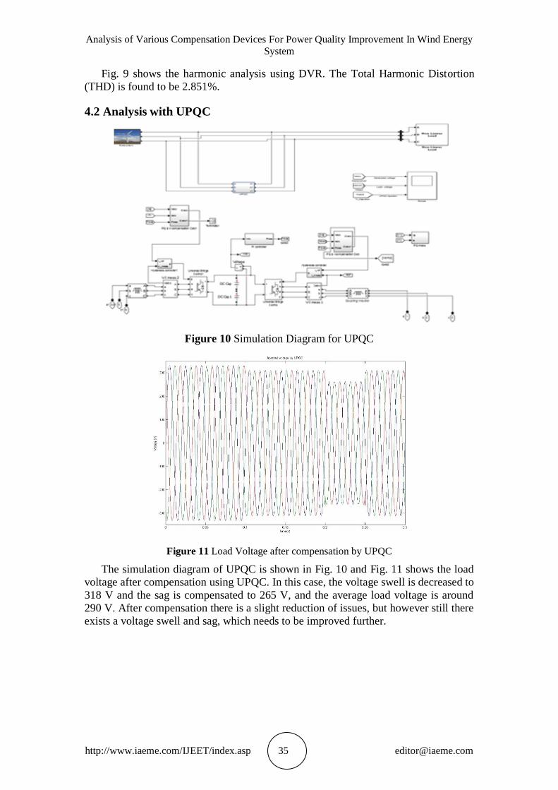
Figure 12 Harmonic Analysis using UPQC
Fig. 9 shows the harmonic analysis using UPQC and the Total Harmonic
Distortion (THD) in this case is found to be 2.281%.Here it was observed that the
voltage profile is slightly increased when compared with DVR compensation and also
the THD value is reduced slightly.
4.3. Analysis with DSTATCOM
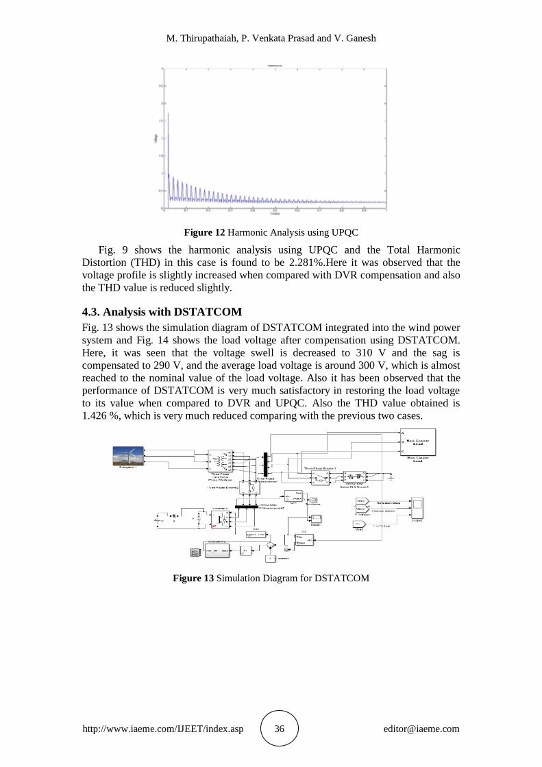
Fig. 13 shows the simulation diagram of DSTATCOM integrated into the wind power
system and Fig. 14 shows the load voltage after compensation using DSTATCOM.
Here, it was seen that the voltage swell is decreased to 310 V and the sag is
compensated to 290 V, and the average load voltage is around 300 V, which is almost
reached to the nominal value of the load voltage. Also it has been observed that the
performance of DSTATCOM is very much satisfactory in restoring the load voltage
to its value when compared to DVR and UPQC. Also the THD value obtained is
1.426 %, which is very much reduced comparing with the previous two cases.
Figure 13 Simulation Diagram for DSTATCOM

Analysis of Various Compensation Devices For Power Quality Improvement In Wind Energy
System
http://www.iaeme.com/IJEET/index.asp 37 [email protected]
Figure 14 Load Voltage after compensation by DSTATCOM
Figure 15 Harmonic Analysis using DSTATCOM
The performance of various devices for the power quality improvement is shown.
The analysis clearly shows that the performance of the DSTATCOM is comparatively
better than the other two devices in terms of improving the voltage profile to its
nominal values and reduction in harmonic levels. This performance variation clearly
shows that the DSTATCOM have better performance than the other two devices DVR
and UPQC and hence DSTATCOM is the suggested device for the power quality
improvement in the distributed power system. The numerical results of the various compensation devices are given in the Table II.
TABLE II Performance Comparison of Devices
PQ Issue At Fault
Condition
DVR
Performance
UPQC
Performance DSTATCOM
Performance
Voltage Swell 345 V 325 V 318 V 310 V
Voltage Sag 240 V 250 V 265 V 290 V
Avg. Load Voltage 270 V 285 V 290 V 300 V
THD 4.028% 2.851% 2.281% 1.426%

M. Thirupathaiah, P. Venkata Prasad and V. Ganesh
http://www.iaeme.com/IJEET/index.asp 38 [email protected]
5. CONCLUSION
The power quality improvement in the distribution system integrated with a wind
turbine is one of the recent research trends. There are many devices used for the
power quality improvement, so it is tough to identify the most suitable device for the
power quality improvement in the distribution system. Hence, this paper presented the
analysis on three major compensation devices for power quality improvement, DVR,
UPQC and DSTATCOM. These three devices are analysed on a common problem in
wind based distribution system. The power quality is analysed based on the voltage
sag and swell measures, the implementation results and its analysis clearly shows the
betterment of the DSTATCOM. So, the DSTATCOM is the most suitable device
which can be used for wind energy system for power quality improvement. In future
scope, the modification of this DSTATCOM can be done to further enhance the
performance for improving the power quality in distribution systems.
REFERENCES
[1] Wanda J. Orlikowski and Jack J. Baroudi, Studying information technology in
organizations: Research approaches and assumptions, Information systems
research, 2(1), pp. 1–28, 1991.
[2] M.S. Dresselhaus and I.L. Thomas, Alternative energy technologies, Nature, 414,
(6861) pp. 332–337, 2001.
[3] Mark Z. Jacobson and Mark A. Delucchi, Providing all global energy with wind,
water, and solar power, Part I: Technologies, energy resources, quantities and
areas of infrastructure, and materials, Energy Policy, 39(3), pp. 1154-1169, 2011.
[4] Bert JM De Vries, Detlef P. van Vuuren, and Monique M. Hoogwijk, Renewable
energy sources: Their global potential for the first-half of the 21st century at a
global level: An integrated approach, Energy policy, 35(4), pp. 2590–2610, 2007.
[5] Joanna I. Lewis, Technology acquisition and innovation in the developing world:
wind turbine development in China and India, Studies in comparative
international development, 42(3–4) pp. 208–232, 2007.
[6] Juan Manuel Carrasco, Leopoldo Garcia Franquelo, Jan T. Bialasiewicz, Eduardo
Galván, RC Portillo Guisado, Ma AM Prats, José Ignacio León, and Narciso
Moreno-Alfonso, Power- electronic systems for the grid integration of renewable
energy sources: A survey, IEEE Transactions on Industrial Electronics, 53(4), pp.
1002–1016, 2006.
[7] J.A. Lopes, N. Hatziargyriou, J. Mutale, P. Djapic, and N. Jenkins, Integrating
distributed generation into electric power systems: A review of drivers,
challenges and opportunities, Electric Power Systems Research, 77(9), pp. 1189–
1203, 2007.
[8] Carolina Vilar, Hortensia Amarís, and Julio Usaola, Assessment of flicker limits
compliance for wind energy conversion system in the frequency domain,
Renewable energy, 31(8), pp. 1089–1106, 2006.
[9] Jiyuan Fan and Stuart Borlase, The evolution of distribution, IEEE Power and
Energy Magazine, 7(2), pp. 63–68, 2009.
[10] Sharad W. Mohod and Mohan V. Aware, A STATCOM-control scheme for grid
connected wind energy system for power quality improvement, IEEE Systems
Journal, 4(3), pp. 346–352, 2010.
[11] Jos Arrillaga, Math HJ Bollen, and Neville R. Watson, Power quality following
deregulation, Proceedings of the IEEE, 88(2), pp. 246–261, 2000.

Analysis of Various Compensation Devices For Power Quality Improvement In Wind Energy
System
http://www.iaeme.com/IJEET/index.asp 39 [email protected]
[12] Rajib Datta and V. T. Ranganathan, A method of tracking the peak power points
for a variable speed wind energy conversion system, IEEE transactions on Energy
conversion, 18(1), pp. 163–168, 2003.
[13] Zhe Chen, Josep M. Guerrero, and Frede Blaabjerg, A review of the state of the
art of power electronics for wind turbines, IEEE Transactions on Power
Electronics, 24(8), pp. 1859–1875, 2009.
[14] Kelvin Tan, and Syed Islam, Optimum control strategies in energy conversion of
PMSG wind turbine system without mechanical sensors, IEEE Transactions on
Energy Conversion, 19(2), pp. 392–399, 2004.
[15] V. Yuvaraj, E. Pratheep Raj, A. Mowlidharan, and L. Thirugnanamoorthy, Power
quality improvement for grid connected wind energy system using FACTS
device, In Proceedings of IEEE Joint 3rd Int'l Workshop on Nonlinear Dynamics
and Synchronization & 16th International Symposium on Theoretical Electrical
Engineering, pp. 1–7. 2011.
[16] Wind Turbine Generating System-Part 21, International standard-IEC 61400-21,
2001.
[17] J. Manel, Power electronic system for grid integration of renewable energy
source: A survey, IEEE Trans. Ind. Electron., 53(4), pp. 1002–1014, 2006,
Carrasco.
[18] M. Tsili and S. Papathanassiou, A review of grid code technology requirements
for wind turbine, Proc. IET Renew. Power gen., 3, pp. 308–332, 2009.
[19] S. Heier, Grid Integration of Wind Energy Conversions. Hoboken, NJ: Wiley,
2007, pp. 256–259.
[20] J.J. Gutierrez, J. Ruiz, L. Leturiondo, and A. Lazkano, Flicker measurement
system for wind turbine certification, IEEE Trans. Instrum. Meas., 58(2), pp.
375–382, Feb. 2009.
[21] Indian Wind Grid Code Draft report on, Jul. 2009, pp. 15–18, C-NET.
[22] El-Habrouk M., Darwish M.K., Mehta P, Active power filters: a review, Electric
Power Applications, IEE Proceedings, 147(5), Sept. 2000, pp. 403–413.
[23] V. Khadkikar, A. Chandra, A. Barry and T.D. Nguyen, Conceptual Study of
Unified Power Quality Conditioner (UPQC), IEEE ISIE 2006, July 9–12, 2006,
Montreal, Quebec, Canada.
[24] Vinod Khadkikar, Enhancing Electric Power Quality Using UPQC: A
Comprehensive Overview, IEEE Transactions on Power Electronics, 27(5), pp.,
2012.
[25] K.Rama Lingeswara Prasad and Dr.K.Chandra Sekhar, A New Sensorless
Control Strategy For A Variable Speed PMSG Wind Energy System Connected
To Grid. International Journal of Electrical Engineering & Technology, 4(5),
2014, pp. 146–154.
[26] Aswathi.N.A, Sneha.M.L, Rashmi and Mohamed Jalaluddin, Power Quality
Improvement by Harmonic Reduction. International Journal of Electrical
Engineering & Technology, 5(8), 2015, pp. 222–232.
[27] S.Munisekhar, O.Hemakesavulu And Dr.M.Padmalalitha, Wind Energy
Conversion Systems Using Fuzzy Controlled Statcom For Power Quality
Improvement. International Journal of Electrical Engineering & Technology,
4(4), 2013, pp. 108–117.
[28] Zhang Hui, Liu Jinjun, Huang Xinming, and WANG Zhaoan, Design of A New
DC Link Voltage Controller for Universal Power Quality Controllers, IEEE
press, Applied power electronics conference, Feb. 25–March 1 2007, pp. 473–
477.