Embed Size (px)
Citation preview
Arduino TRE
Reference Documentation Beta Testing Program
Version 0.5 Status: DRAFT
Updated on 20th feb. 2015

Product description
Overview Arduino TRE, the first Arduino board manufactured in the U.S. Thanks to the 1GHz Sitara AM335x processor, Arduino developers get up to 100 times more performance with the Sitaraprocessorbased Arduino TRE than they do on the Arduino Leonardo or Uno. This performance opens the doors to more advanced Linuxpowered applications. The Sitaraprocessorbased Linux Arduino can run highperformance desktop applications, processingintensive algorithms or highspeed communications. The Arduino TRE is two Arduinos in one: the Sitaraprocessorbased Linux Arduino plus a full AVRbased Arduino. While leveraging the simplicity of the Arduino software experience, the integration of the AVR Arduino enables the Arduino TRE to use the existing shield ecosystem so that innovators can expand the Arduino TRE to develop a wide range of highperformance applications such as 3D printers, gateways for building automation and lighting automation, telemetry hubs that collect data from nearby sensors wirelessly, other connected applications that require host control plus realtime operations and much more. In addition, the Arduino TRE is partially the result of a close collaboration between Arduino and the BeagleBoard.org foundation. These open hardware pioneers share a passion for expanding open source development and making technology accessible for artists, designers and hobbyists. The Arduino TRE design builds upon the experience of both Arduino and BeagleBoard.org, combining the benefits of both community based boards.

WARNINGS
Use only a regulated 5V, positive central power supply. Any other power supply can damage the board.
Do not exceed the current limits for the Sitara processor pins or the processor can
be damaged! See here for more details.
Incompatible shields can damage the board. For any shield that is not explicitly declared to be compatible with the Arduino TRE, cut or bend the shield VIN pin header before connecing the shield to the board.
Do not (un)plug any cable or shield while the board is powered on.
The Developer Edition board is a preproduction release: the final board may differ
in any degree from the Developer Edition one.
There is no password set for the root user.
Arduino TRE does not work without Sd inserted. Please note do not insert / eject SD Card when the board is ON. Be sure to switch OFF the board before insert or eject the SD card.
DO NOT shorts all the two power jumpers behind the 5v connector.
NOTE
This document is work in progress. For any question or doubt please post your questions on the Basecamp project before trying to do something that can be harmful for the board.
Known Issues Please take a look here for the updated list.

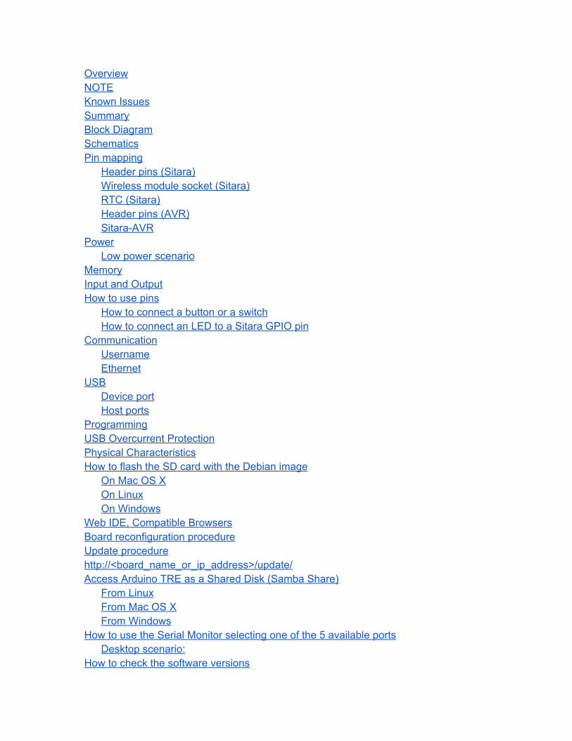
Overview NOTE Known Issues Summary Block Diagram Schematics Pin mapping
Header pins (Sitara) Wireless module socket (Sitara) RTC (Sitara) Header pins (AVR) SitaraAVR
Power Low power scenario
Memory Input and Output How to use pins
How to connect a button or a switch How to connect an LED to a Sitara GPIO pin
Communication Username Ethernet
USB Device port Host ports
Programming USB Overcurrent Protection Physical Characteristics How to flash the SD card with the Debian image
On Mac OS X On Linux On Windows
Web IDE, Compatible Browsers Board reconfiguration procedure Update procedure http://<board_name_or_ip_address>/update/ Access Arduino TRE as a Shared Disk (Samba Share)
From Linux From Mac OS X From Windows
How to use the Serial Monitor selecting one of the 5 available ports Desktop scenario:
How to check the software versions
LibArduino (Sitara Arduino Core) Appendix
USB hot plug temporary fix How to enable the fix How to disable the fix
CAN bus utilities How to install the package How to remove the package
Warnings Differences with other Arduino boards How to activate and use Web browser log System block diagram Notes
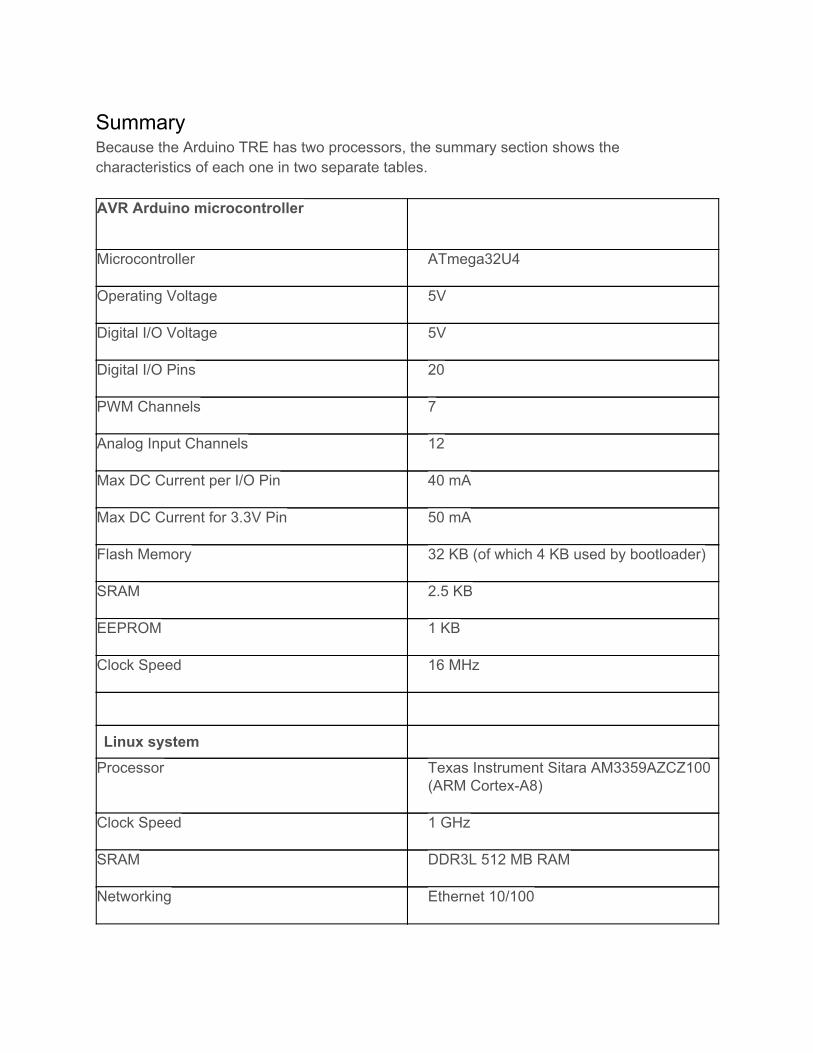
Summary Because the Arduino TRE has two processors, the summary section shows the characteristics of each one in two separate tables. AVR Arduino microcontroller
Microcontroller ATmega32U4
Operating Voltage 5V
Digital I/O Voltage 5V
Digital I/O Pins 20
PWM Channels 7
Analog Input Channels 12
Max DC Current per I/O Pin 40 mA
Max DC Current for 3.3V Pin 50 mA
Flash Memory 32 KB (of which 4 KB used by bootloader)
SRAM 2.5 KB
EEPROM 1 KB
Clock Speed 16 MHz
Linux system
Processor Texas Instrument Sitara AM3359AZCZ100 (ARM CortexA8)
Clock Speed 1 GHz
SRAM DDR3L 512 MB RAM
Networking Ethernet 10/100

USB port 1 USB 2.0 device port, 4 USB 2.0 host ports
Video HDMI (1920x1080)
Audio HDMI digital audio, stereo analog audio input and output
Digital I/O Pins (3.3V logic) 23
PWM Channels (3.3V logic) 4
Max DC Current per I/O Pin 6 mA (sink and source)
On board storage capability MicroSD card slot
LCD expansion connector FPDLink
Block Diagram [...]
Schematics EAGLE files: [TODO] Schematics: [TODO]
Pin mapping
Header pins (Sitara) Pin Number Pin Name Mapped Pin Name Notes
V15 GPIO1_21 96, YELLOW_LED
U15 GPIO1_22 97, RED_LED
V16 GPIO1_24 98, GREEN_LED, LED_BUILTIN
T15 GPIO1_23 99, BLUE_LED
U10 GPIO0_22 100 (PWM)

T10 GPIO0_23 101 (PWM)
U14 GPIO1_18 102 (PWM)
T14 GPIO1_19 103 (PWM)
U7 GPIO1_0 104
V7 GPIO1_1 105
R8 GPIO1_2 106
T8 GPIO1_3 107
U8 GPIO1_4 108
V8 GPIO1_5 109
R9 GPIO1_6 110
T9 GPIO1_7 111
T13 GPIO2_0 112
U6 GPIO2_4 113
T7 GPIO2_3 114
R7 GPIO2_2 115
T11 GPIO0_26 116
B12 GPIO3_18 117
C13 GPIO3_19 118
D13 GPIO3_20 119
U9 GPIO1_30 120
V9 GPIO1_31 121
T12 GPIO1_12 122
R12 GPIO1_13 123
V13 GPIO1_14 124
U13 GPIO1_15 125
A15 GPIO0_19 126

D14 GPIO0_20 127
A16 I2C1_SCL SCL1 4.75kOhm pullup resistor connected to 3.3Vb internal
rail
B16 I2C1_SDA SDA1 4.75kOhm pullup resistor connected to 3.3Vb internal
rail
E18 SPI1_D0 MOSI1
E17 SPI1_D1 MISO1
H16 SPI1_SCLK SCK1
C18 SPI1_CS1 SS1
U17 UART4_TXD TX1 Is it mapped?
T17 UART4_RXD RX1 Is it mapped?
L18 UART2_TXD TX2 /dev/ttyO2
K18 UART2_RXD RX2 /dev/ttyO2
Wireless module socket (Sitara) Socket Pin Number
Socket Pin Name Sitara Pin Name Notes
1 3.3V
2 TX UART1_RXD
3 RX UART1_TXD
4 n.c.
5 RESET GPIO1_20
6 n.c.
7 n.c.
8 n.c.
9 DTR GPIO2_18
10 GND
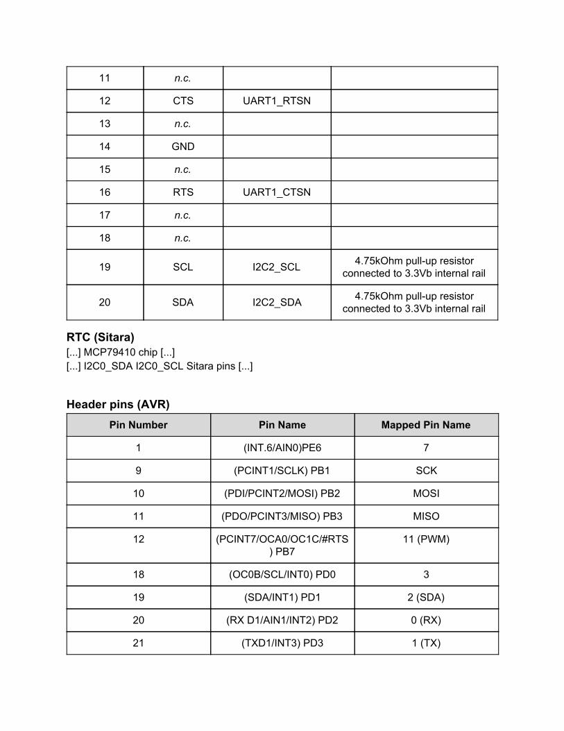
11 n.c.
12 CTS UART1_RTSN
13 n.c.
14 GND
15 n.c.
16 RTS UART1_CTSN
17 n.c.
18 n.c.
19 SCL I2C2_SCL 4.75kOhm pullup resistor connected to 3.3Vb internal rail
20 SDA I2C2_SDA 4.75kOhm pullup resistor connected to 3.3Vb internal rail
RTC (Sitara) [...] MCP79410 chip [...] [...] I2C0_SDA I2C0_SCL Sitara pins [...]
Header pins (AVR) Pin Number Pin Name Mapped Pin Name
1 (INT.6/AIN0)PE6 7
9 (PCINT1/SCLK) PB1 SCK
10 (PDI/PCINT2/MOSI) PB2 MOSI
11 (PDO/PCINT3/MISO) PB3 MISO
12 (PCINT7/OCA0/OC1C/#RTS) PB7
11 (PWM)
18 (OC0B/SCL/INT0) PD0 3
19 (SDA/INT1) PD1 2 (SDA)
20 (RX D1/AIN1/INT2) PD2 0 (RX)
21 (TXD1/INT3) PD3 1 (TX)

25 (ICP1/ADC8) PD4 4
26 (T1/#OC4D/ADC9) PD6 12
27 (T0/OC4D/ADC10) PD7 6
28 (ADC11/PCINT4) PB4 8
29 (PCINT5/OC1A/#OC4B/ADC12) PB5
9 (PWM)
30 (PCINT6/OC1B/OC4B/ADC13) PB6
10 (PWM)
31 (OC3A/#0C4A) PC6 5 (PWM)
32 (ICP3/CLK0/)C4A) PC7 13 (PWM)
36 (ADC7/TDI) PF7 A0
37 (ADC6/TDO) PF6 A1
38 (ADC5/TMS) PF5 A2
39 (ADC4/TCK) PF4 A3
40 (ADC1) PF1 A4
41 (ADC0) PF0 A5
42 AREF AREF
43 GND3 GND
44 AVCC1 AVCC
SitaraAVR Enable pins Check document posted by Biagio Montaruli https://basecamp.com/2546761/projects/5640281/todos/95781092 TODO 32U4 reset echo 65 > /sys/class/gpio/export echo out > /sys/class/gpio/gpio65/direction
echo 1 > /sys/class/gpio/gpio65/value echo 0 > /sys/class/gpio/gpio65/value echo 65 > /sys/class/gpio/unexport [...] Board/Sitara ON/OFF [...]
Power The Arduino TRE can be powered only via the DC plug connector with a 5V external power supply. The power management circuit on the board supplies power to the two processors on the board and all the other on board peripherals.
The input voltage for the power supply accepts only regulated 5V. Any different voltage can damage the board. To guarantee that the Linux system receives enough power to run correctly we suggest that you use a power supply that can provide at least 2A. If you want to use one or more of the on board USB ports, it’s best to use a 5A supply. The adapter can be connected by plugging a 2.1mm centerpositive plug into the board's power jack.
Low power scenario DO NOT shorts all the two power jumpers behind the 5v connector.
Close to the DC plug there is a jumper that allows you to select the power supply method of the Arduino TRE

When in the default position (position A in the photo) the jumper is set to power up both the processors on the board, the Sitara running the Linux system and the AVR microcontroller. Because most of power consumption is due to the Linux system, you may want to power it off when you don’t need it.
Moving the jumper to position B the AVR microcontroller is always powered on and can switch on and off the Linux system.
The Arduino TRE can be powered by a LiPo battery. [TBV]
insert Image
The power pins are as follows: VIN. Unlike the other Arduino boards this pin isn’t an input pin. You should not
connect a power supply or a battery to this pin. Is an output pin for the the 5V provided by the external power supply. On the Arduino TRE this pin is internally connected to the 5V pin when the jumper is in the B position and to 5Va pin when the jumper is in the A position.
5V. This pin outputs a regulated 5V from the regulator on the board. On the Arduino TRE this pin is internally connected to the VIN pin.
3.3V. 3.3 Volt power supply pin. The output voltage is generated by the onboard regulator. Maximum current draw is [TBV]mA.
GND. Ground pins. IOREF. This pin on the Arduino board provides the voltage reference at which the
AVR microcontroller (ATmega32U4) operates. A properly configured shield can read
the IOREF pin voltage and select the appropriate power source or enable voltage translators on the outputs for working with the 5V or 3.3V.
BATT +/. On these connectors you can solder the leads of a 3V coin backup battery for the onboard real time clock (RTC) chip (MCP79410).
BAT. This pin is the input pin where you can connect the positive lead of a LiPo battery [TBV]
BTS. This pin is the input pin for the temperature sensor of the LiPo battery [TBV] BSNS. This pin is the the input pin for a current sensor connected to the LiPo battery.
[TBV]
Memory
The ATmega32U4 has 32 KB of flash memory (with 4 KB are used for the bootloader) used to upload the sketches. It also has 2.5 KB of SRAM and 1 KB of EEPROM (which can be read and written with the EEPROM library).
The memory on the Sitara is not embedded inside the processor. The RAM and the storage memory are externally connected. The Arduino TRE has 512 MB of DDR3 RAM and doesn’t have flash memory. The Linux system and the storage memory are on the SD card. The Arduino TRE comes with a 8GB micro SD card with the preloaded Linux image based on Debian. Once inserted inside the micro SD card slot the Arduino TRE is ready to go. The Arduino TRE can’t run without the SD card preloaded with the Linux image.
Input and Output The Arduino TRE has numerous inputs, outputs and interface pins broken out on the various pin headers present on the board. The standard Arduino I/O footprint is accessible in the area marked in white in the centre of the board. These pins are connected only to the Atmega32U4 and the pin layout on these headers is the same you find on the Arduino Leonardo or Yún. All the Arduino compatible shield are stackable on this pin headers. The new Arduino pins footprint format introduced with the Arduino TRE is composed by four doublerows pin headers distributed externally on two side of the board. On this footprint both the Atmega32U4 and the Sitara pins are accessible. The pins connected to the Atmega32U4 are grouped together and marked in white. All the other pins are connected to the Sitara processor. The Sitara pins operate at 3.3V and can source and sink a maximum of 6 mA. The Sitara pins must be handled with care because they are more fragile than the AVR pins.
Atmega32U4 pins details: see Arduino YUN Sitara pins details:
RGB LED The Red, Green and Blue LEDs are accessible as digital pins as 97, 98 and 99. The Green LED is also accessible as LED_BUILTIN.
SD LED The Yellow LED that generally indicates the status of the SD card is accessible as digital pin number 96.
PWM: Pins 100 to 103 Provide 8bit PWM output with the analogWrite() function. The resolution of the PWM can be changed with the analogWriteResolution() function.
Digital I/O: Pins 104 to 127 Each of the 23 digital pins on the Arduino TRE can be used as an input or output, using pinMode(), digitalWrite(), and digitalRead() functions. They operate at 3.3 Volts. Each pin can provide (source) a current of 6 mA, or accept (sink) a current of 6 mA. They also have an internal pullup and pulldown resistors (disconnected by default) of [TBV] kOhm.
Serial: RX and TX connected to the wireless module socket
Serial1: RX1 and TX1
Serial2: RX2 and TX2
TWI1: SDA1 and SCL1
TWI2: SDA2 and SCL2 connected to the wireless module socket
SPI1: MOSI1, MISO1, SCK1 and SS1 CAN BUS: CANH, CANL, CAN5 and CGND FPDLink: CLK+, CLK, Y0+, Y0, Y1+, Y1, Y2+ and Y2 LRST: Stiara reset line (short to GND to reset the processor) BAT BTS BSNS ONOFF
How to use pins The pins on the Arduino TRE headers have limited current source and sink capability, so special care should be taken when external components are connected to the board. The following notes apply specifically to the header pins connected to the Sitara processor (lower current capability, 3.3V logic), but the same considerations are valid also for the pins connected to the AVR processor (higher current capability, 5V logic).
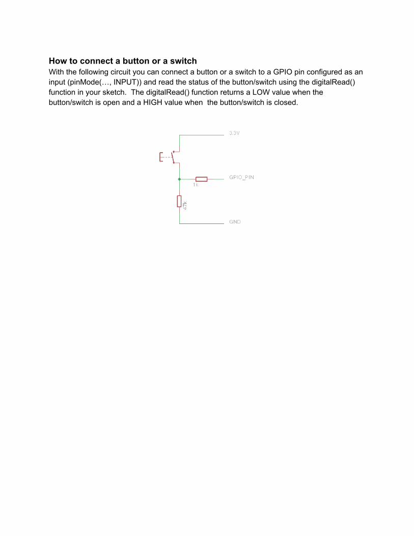
How to connect a button or a switch With the following circuit you can connect a button or a switch to a GPIO pin configured as an input (pinMode(…, INPUT)) and read the status of the button/switch using the digitalRead() function in your sketch. The digitalRead() function returns a LOW value when the button/switch is open and a HIGH value when the button/switch is closed.
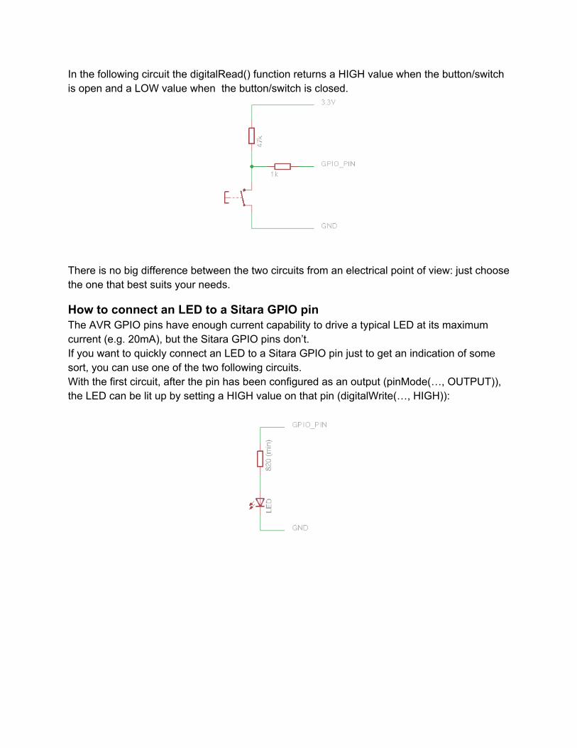
In the following circuit the digitalRead() function returns a HIGH value when the button/switch is open and a LOW value when the button/switch is closed.
There is no big difference between the two circuits from an electrical point of view: just choose the one that best suits your needs.
How to connect an LED to a Sitara GPIO pin The AVR GPIO pins have enough current capability to drive a typical LED at its maximum current (e.g. 20mA), but the Sitara GPIO pins don’t. If you want to quickly connect an LED to a Sitara GPIO pin just to get an indication of some sort, you can use one of the two following circuits. With the first circuit, after the pin has been configured as an output (pinMode(…, OUTPUT)), the LED can be lit up by setting a HIGH value on that pin (digitalWrite(…, HIGH)):
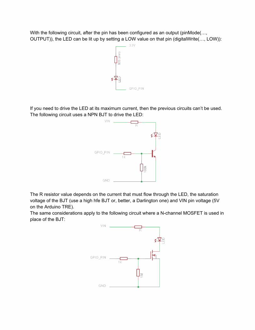
With the following circuit, after the pin has been configured as an output (pinMode(…, OUTPUT)), the LED can be lit up by setting a LOW value on that pin (digitalWrite(…, LOW)):
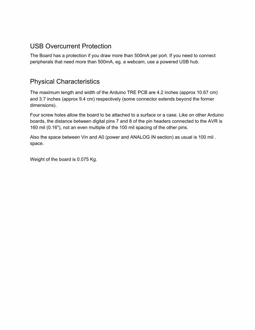
If you need to drive the LED at its maximum current, then the previous circuits can’t be used. The following circuit uses a NPN BJT to drive the LED:
The R resistor value depends on the current that must flow through the LED, the saturation voltage of the BJT (use a high hfe BJT or, better, a Darlington one) and VIN pin voltage (5V on the Arduino TRE). The same considerations apply to the following circuit where a Nchannel MOSFET is used in place of the BJT:
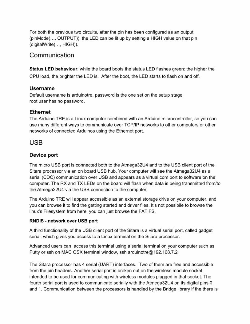
For both the previous two circuits, after the pin has been configured as an output (pinMode(…, OUTPUT)), the LED can be lit up by setting a HIGH value on that pin (digitalWrite(…, HIGH)).
Communication Status LED behaviour: while the board boots the status LED flashes green: the higher the CPU load, the brighter the LED is. After the boot, the LED starts to flash on and off.
Username Default username is arduinotre, password is the one set on the setup stage. root user has no password.
Ethernet The Arduino TRE is a Linux computer combined with an Arduino microcontroller, so you can use many different ways to communicate over TCP/IP networks to other computers or other networks of connected Arduinos using the Ethernet port.
USB
Device port
The micro USB port is connected both to the Atmega32U4 and to the USB client port of the Sitara processor via an on board USB hub. Your computer will see the Atmega32U4 as a serial (CDC) communication over USB and appears as a virtual com port to software on the computer. The RX and TX LEDs on the board will flash when data is being transmitted from/to the Atmega32U4 via the USB connection to the computer.
The Arduino TRE will appear accessible as an external storage drive on your computer, and you can browse it to find the getting started and driver files. It’s not possibile to browse the linux’s Filesystem from here. you can just browse the FAT FS.
RNDIS network over USB port
A third functionality of the USB client port of the Sitara is a virtual serial port, called gadget serial, which gives you access to a Linux terminal on the Sitara processor.
Advanced users can access this terminal using a serial terminal on your computer such as Putty or ssh on MAC OSX terminal window, ssh [email protected] The Sitara processor has 4 serial (UART) interfaces. Two of them are free and accessible from the pin headers. Another serial port is broken out on the wireless module socket, intended to be used for communicating with wireless modules plugged in that socket. The fourth serial port is used to communicate serially with the Atmega32U4 on its digital pins 0 and 1. Communication between the processors is handled by the Bridge library if the there is

an active Linux terminal on the Sitara. It can also be used as a plain serial communication port by disabling the Linux terminal. It operates at a maximum speed of [TBV]. On the board there is a wireless module socket that is connected to the Sitara using a dedicated serial interface.
A SoftwareSerial library allows for serial communication on most of the Atmega32U4 digital pins except for pins 0 and 1.
The ATmega32U4 also supports TWI and SPI communication. The Arduino software includes a Wire library to simplify use of the TWI bus; see the documentation for details. For SPI communication, use the SPI library.
The Sitara also supports TWI and SPI communication. The Arduino software includes a Wire library to simplify use of the TWI bus.
The Atmega32U4 on the Arduino TRE also appears as a generic keyboard and mouse, and can be programmed to control these input devices using the Keyboard and Mouse classes.
Host ports
The Arduino TRE has also four USB host ports where is possible to plug any USB device that can be attached to a computer.
Programming The Arduino TRE revolutionizes the way you can program an Arduino because the programming environment, called WEB IDE, is integrated inside the board, on the linux processor. The Arduino programming environment is inside the browser and you can access it by connecting the board to the local network through the Ethernet cable or either connecting the USB client port (micro usb connector) to your computer. The Arduino TRE Web IDE will let you select the target you want to program, the Sitara processor or the Atmega32U4. The Sitara processor will compile and upload the sketch directly on the board. Without the need of a phisical connected PC, you can can write a sketch, using the Arduino language, to control the pins connected to the Sitara processor. The Atmega32U4 can be also programmed with the traditional Arduino desktop IDE if the Arduino TRE is connected to the computer with the USB cable. The ATmega32U4 (the same found on Arduino Leonardo board) on the Arduino TRE comes preburned with a bootloader that allows you to upload new code to it without the use of an external hardware programmer. It communicates using the AVR109 protocol. You can also bypass the bootloader and program the microcontroller through the ICSP (InCircuit Serial Programming) header; see these instructions for details.
USB Overcurrent Protection The Board has a protection if you draw more than 500mA per port. If you need to connect peripherals that need more than 500mA, eg. a webcam, use a powered USB hub.
Physical Characteristics The maximum length and width of the Arduino TRE PCB are 4.2 inches (approx 10.67 cm) and 3.7 inches (approx 9.4 cm) respectively (some connector extends beyond the former dimensions).
Four screw holes allow the board to be attached to a surface or a case. Like on other Arduino boards, the distance between digital pins 7 and 8 of the pin headers connected to the AVR is 160 mil (0.16"), not an even multiple of the 100 mil spacing of the other pins.
Also the space between Vin and A0 (power and ANALOG IN section) as usual is 100 mil . space.
Weight of the board is 0.075 Kg.

How to flash the SD card with the Debian image
On Mac OS X For the following procedure you need to open a terminal window and use the command line tools. The purpose is to make an exact copy of the fresh Linux Debian image that you downloaded from your computer to the micro SD card. WARNING!!! THE DD COMMAND IS DANGEROUS. IF USED INCORRECTLY IT CAN WIPE OUT YOUR HDDs! BACKUP YOUR DATA FIRST! Instructions to flash the card:
Download the Linux Debian image for the Arduino TRE. Do not connect the SD card you want to flash yet. Uncompress the SD image file (for the .XZ extension you can download the free “The
Unarchiver” app from the Apple App Store) on your Mac HDD Login with a user that has administrator privileges Open a terminal window and type the following:
ls /dev/disk* and take note of the mounted disks; for example:
/dev/disk0 /dev/disk0s1 /dev/disk0s2 /dev/disk0s3 Now connect the SD card and run the ‘ls’ command again
ls /dev/disk* You should see now one new disk; for example (disk1):
/dev/disk0 /dev/disk0s1 /dev/disk0s2 /dev/disk0s3 /dev/disk1 /dev/disk1s1 /dev/disk1s2 /dev/disk1s3
Unmount every partition on the SD card, if any; in the previous example you should run diskutil umount /dev/disk1s1 diskutil umount /dev/disk1s2 diskutil umount /dev/disk1s3
Now ‘cd’ to the directory on Mac HDD where you unpacked the SD card image (e.g. arduinotredebian0.10.2.img), run this command: sudo dd if=./arduinotredebian0.0.2.img of=/dev/rdisk1 bs=1m
and wait… (you can check the progress by pressing CTRLT). At the end, eject the SD card and remove it from your Mac/computer.
On Linux [TBV] (Tested on Ubuntu 13.04, but should work with little changes in other distributions) Preliminary notes The instruction here assume full root access to the system (sudo su) and not only sudo permissions. This matters because a command like
sudo xz cd ./ubuntu13.04armhfminfs*.img.xz > /dev/sdX is actually two commands in one, and thus the sudo is elevating only the xz command to root, which we don’t need, and executing the stdout redirect (> /dev/sdX) as unelevated shell (which will produce a permission error). So before executing this guide open a root terminal (open a terminal and run sudo su). WARNING: Please be really careful in executing these actions. Your are using a root shell to perform a low level binary copy onto a specific memory device, selecting the wrong device (for example your hard drive instead of the SD memory) will permanently erase your data and corrupt your drive. This tutorial is safe but be careful. Note: You cannot operate at low level on mounted device, so be sure to unmount SD device before continuing! 1 Download the latest Arduino TRE build image 2 Discover the SD card
First step is to understand at which device the SD card is located. Run in the terminal (before inserting the SD card):
ls /dev/sd* /dev/mmc* Now insert the SD and rerun the previous command. You should now see a new device appearing with 2 partitions; on Ubuntu will it be /dev/mmcblkX (device), /dev/mmcblkXp1 (partition 1), /dev/mmcblkXp2 (partition 2). X is a progressive number indicating the number of the device (so if you have three memory block device attached will be 2, counting from 0). We are interested in the device, so in the Ubuntu example you should use /dev/mmcblkX.

3 Flash the image
To flash the image you need the xz shell utility, install it with:
aptget install xzutil Now you're ready! cd to the folder in which you have the downloaded image and run:
xz cd ./arduinotredebian0.0.2.img.xz > /dev/mmcblkX Please double check device name, this step can be REALLY dangerous This command will run xz in decompression mode and send uncompressed data to stdout; then we redirect stdout to the SD card device. No feedback is provided in whatsoever way, so you have to wait till the command ends executing. (or you can use a program to check io stats to follow the progress) When xz execution ends you have completed the process.
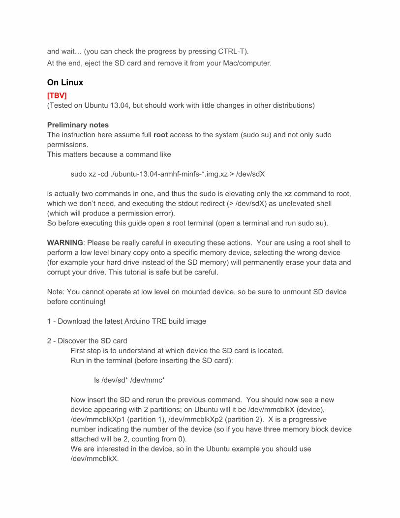
On Windows For those people having trouble with their SD Cards, use a tool called win32diskimager (http://sourceforge.net/projects/win32diskimager/) it's free to use and download. You will need administrative rights to run and use it. You will have to have your SD Card connected via an adapter or reader. The TRE image you download, extract it first using 7zip (http://www.7zip.org/download.html) this step may not be necessary but I would advise it for making the win32diskimager software do less work.
Select the appropriate letter of your SD Card under “device” dropdown, select the TRE image downloaded and click on “write” button.

Web IDE, Compatible Browsers Desktop version Safari, 6.2 onward Firefox, 30 onward Chrome, 35 onward Not compatible with Internet Explorer (any version)
Board reconfiguration procedure Eject the micro SD from your board Place the micro SD in the SD adaptor Insert the SD adaptor in your computer You will see 2 partitions showing up in your File System: Arduino_Tre and Tre_Boot Open Tre_Boot, you will find a file called configured.conf Delete configured.conf Eject both partitions Place the micro SD back in the board Plug the TRE into the power supply Connect the TRE to your computer via the micro USB cable After a couple of minutes the partition Arduino_Tre will show up in your File System Open it and run TreSetup.html one more time
Update procedure You can update your board with the latest updates using http://<board_name_or_ip_address>/update/ press update to begin the process.

Access Arduino TRE as a Shared Disk (Samba Share) [...]
From Linux [...]
From Mac OS X [...]
From Windows [...]
How to use the Serial Monitor selecting one of the 5 available ports [...]
Install a WiFi dongle You can add to the Arduino TRE the capability to connect to a WiFi network simply connecting a WiFi dongle to one of the USB ports on the board.
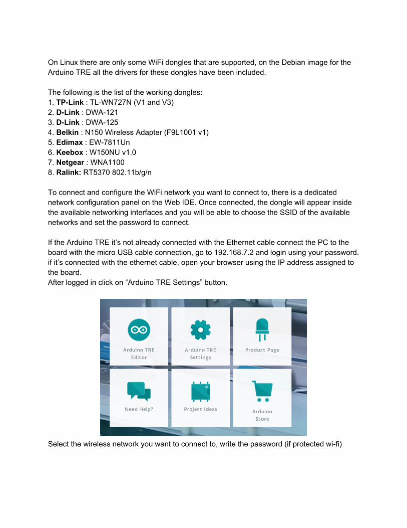
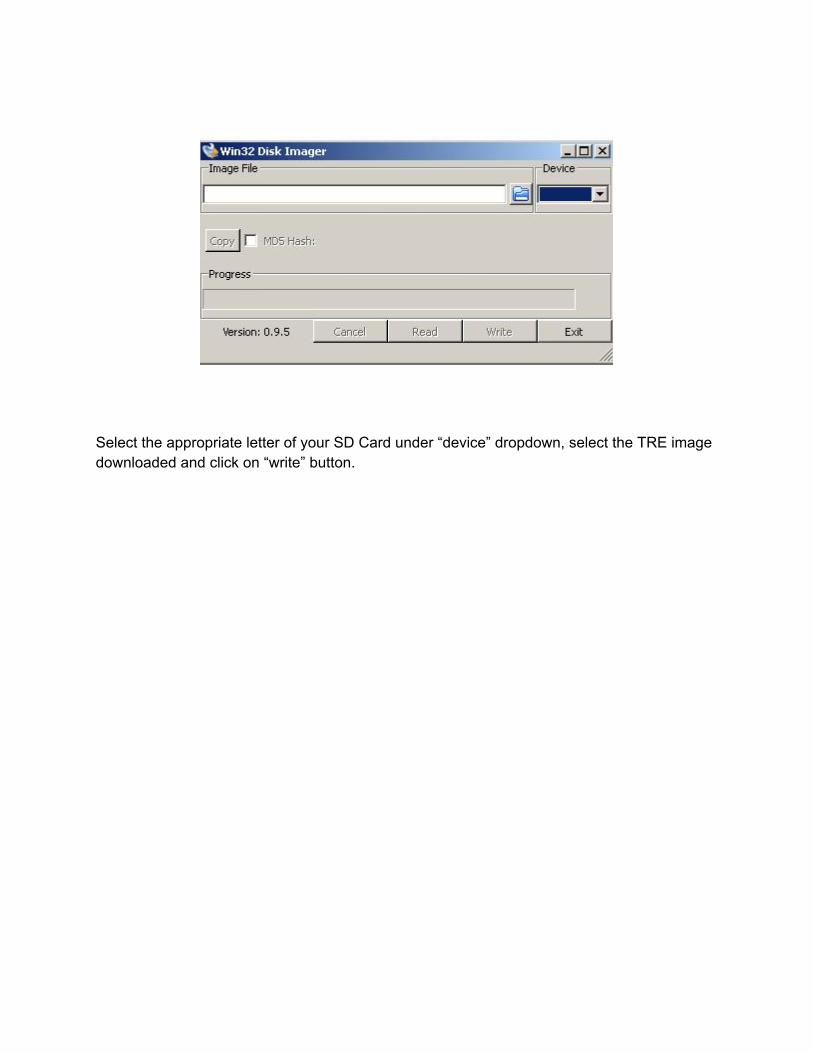
On Linux there are only some WiFi dongles that are supported, on the Debian image for the Arduino TRE all the drivers for these dongles have been included. The following is the list of the working dongles: 1. TPLink : TLWN727N (V1 and V3) 2. DLink : DWA121 3. DLink : DWA125 4. Belkin : N150 Wireless Adapter (F9L1001 v1) 5. Edimax : EW7811Un 6. Keebox : W150NU v1.0 7. Netgear : WNA1100 8. Ralink: RT5370 802.11b/g/n To connect and configure the WiFi network you want to connect to, there is a dedicated network configuration panel on the Web IDE. Once connected, the dongle will appear inside the available networking interfaces and you will be able to choose the SSID of the available networks and set the password to connect. If the Arduino TRE it’s not already connected with the Ethernet cable connect the PC to the board with the micro USB cable connection, go to 192.168.7.2 and login using your password. if it’s connected with the ethernet cable, open your browser using the IP address assigned to the board. After logged in click on “Arduino TRE Settings” button.
Select the wireless network you want to connect to, write the password (if protected wifi)
wait some time for wireless connection and IP assignment (if DHCP server is on) and you are ready to connect to your board from the ip assigned.
Desktop scenario: If your Arduino TRE is connected to a display, keyboard and mouse you can configure the WiFi network with the network manager present on the Debian distribution.
How to check the software versions You can check the current version of different part of the Arduino Tre system in various way: SSH to TRE and launch cat /etc/arduino_version command. You should expect an output like this: root@rantolino:/home/arduinotre# cat /etc/arduino_version 0.0.12 where 0.0.12 is the current image version.
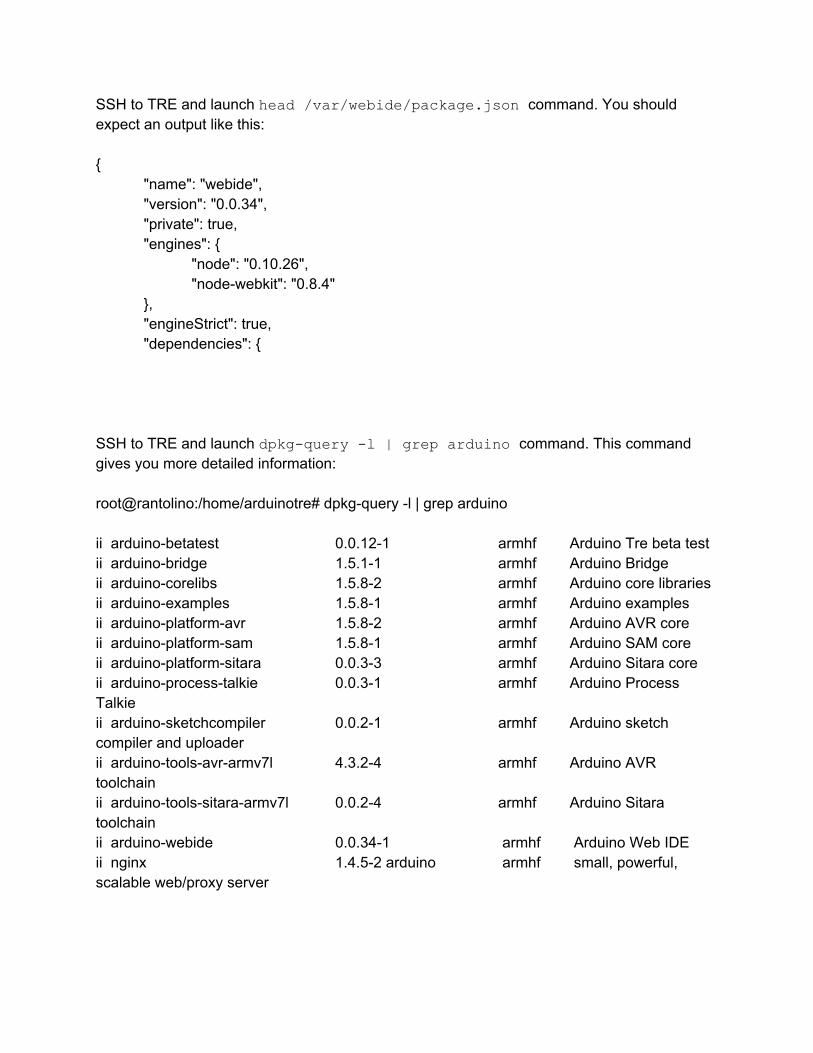
SSH to TRE and launch head /var/webide/package.json command. You should expect an output like this:
"name": "webide", "version": "0.0.34", "private": true, "engines":
"node": "0.10.26", "nodewebkit": "0.8.4"
, "engineStrict": true, "dependencies":
SSH to TRE and launch dpkgquery l | grep arduino command. This command gives you more detailed information: root@rantolino:/home/arduinotre# dpkgquery l | grep arduino ii arduinobetatest 0.0.121 armhf Arduino Tre beta test ii arduinobridge 1.5.11 armhf Arduino Bridge ii arduinocorelibs 1.5.82 armhf Arduino core libraries ii arduinoexamples 1.5.81 armhf Arduino examples ii arduinoplatformavr 1.5.82 armhf Arduino AVR core ii arduinoplatformsam 1.5.81 armhf Arduino SAM core ii arduinoplatformsitara 0.0.33 armhf Arduino Sitara core ii arduinoprocesstalkie 0.0.31 armhf Arduino Process Talkie ii arduinosketchcompiler 0.0.21 armhf Arduino sketch compiler and uploader ii arduinotoolsavrarmv7l 4.3.24 armhf Arduino AVR toolchain ii arduinotoolssitaraarmv7l 0.0.24 armhf Arduino Sitara toolchain ii arduinowebide 0.0.341 armhf Arduino Web IDE ii nginx 1.4.52 arduino armhf small, powerful, scalable web/proxy server

LibArduino (Sitara Arduino Core)
23 GPIO pins:
digitalRead()
digitalWrite()
tempi di propagazione [TBV]
4 PWM pins:
analogWrite()
analogWriteResolution()
features? possibility to change the frequency…?
TWI:
list the supported functions, for example it can work only as a master
SPI:
maximum supported speed?
how many SS pins can handle?
Serial ports:
supported speeds?
additional features in addition to the ones present for the AVRs?
Stepper:
particular care on connecting the Hbridge to the linux GPIO?
LiquidCrystal:
[...]
CAN BUS:
the library has been developed, but can’t be used on the Developer Edition board because of an hardware bug.

Appendix
USB hot plug temporary fix We are now working on a fix for the USB hot plug issue, but it’s not active by default because we are investigating on an issue: if a device is quickly plugged/unplagged or if a connected device reenumerates (e.g. when programming an external Arduino Leonardo), the USB port or the entire board get unstable.
How to enable the fix Open a shell terminal, login as root and run the following commands:
mv /etc/init.d/boot_scripts.sh /root/USBTemporaryFix/boot_scripts.sh.BAK mv /boot/uImage /root/USBTemporaryFix/uImage.BAK cp /root/USBTemporaryFix/boot_scripts.sh /etc/init.d/boot_scripts.sh cp /root/USBTemporaryFix/uImage /boot/uImage chmod a+x /etc/init.d/boot_scripts.sh poweroff
When the board is powerd on again the fix is active.
How to disable the fix Open a shell terminal, login as root and run the following commands:
mv /root/USBTemporaryFix/boot_scripts.sh.BAK /etc/init.d/boot_scripts.sh mv /root/USBTemporaryFix/uImage.BAK /boot/uImage chmod a+x /etc/init.d/boot_scripts.sh poweroff
When the board is powerd on again the fix is not active anymore.
CAN bus utilities The CAN utilities package contains some utility that is helpful for debugging the CAN bus communication.
How to install the package
Run as root the following commands:
cd /tmp
wget http://http.us.debian.org/debian/pool/main/c/canutils/canutils_0.0+git201402271_armhf.deb
dpkg i canutils_0.0+git201402271_armhf.deb
How to remove the package
Installing the package breaks some dependency, so the board update process can’t run. Removing the CAN utilities package running this command as root
dpkg r canutils

solves the issue. After the board update, the CAN utilities package can be installed again, if needed.
Warnings /etc/network/interfaces generated/overwritten by the Web IDE [...]
Differences with other Arduino boards Bridge serial port speed Pin 100103 are configured and can be used as PWM output only The DC plug specifications (electrical) Vin pin Pin current limits [...]
How to activate and use Web browser log Chrome/Chromium [...] Firefox [...] Safari [...]
System block diagram [...]
Notes All the GPIO pins are automatically exported at boot Add an high level block diagram that represents the internal/external ports/connections
with the names used to access them from the Arduino sketches or from Debian Core/libraries/build versions: 1.5.5r2 Motor shield Vin pin warning!!!