Embed Size (px)
Citation preview
Chapter 18
Comment: This chapter, when taught immediately after Chapter 7, has the advantage of im-mediately applying the fatigue information acquired in Chapter 7. We have often done itourselves. However, the disadvantage is that many of the items attached to the shaft haveto be explained sufficiently so that the influence on the shaft is understood. It is the in-structor’s call as to the best way to achieve course objectives.
This chapter is a nice note upon which to finish a study of machine elements. A verypopular first design task in the capstone design course is the design of a speed-reducer, inwhich shafts, and many other elements, interplay.
18-1 The first objective of the problem is to move from shaft attachments to influences on theshaft. The second objective is to “see” the diameter of a uniform shaft that will satisfy de-flection and distortion constraints.
(a)
dP + (80/16)dP
2= 12 in
dP = 4.000 in
W t = 63 025(50)
1200(4/2)= 1313 lbf
Wr = W t tan 25° = 1313 tan 25° = 612 lbf
W = W t
cos 25°= 1313
cos 25°= 1449 lbf
T = W t (d/2) = 1313(4/2) = 2626 lbf · in
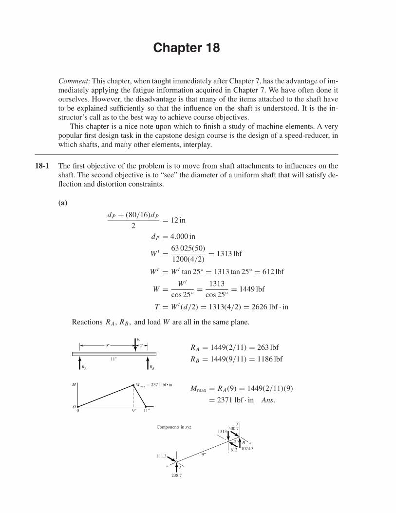
Reactions RA, RB , and load W are all in the same plane.
RA = 1449(2/11) = 263 lbf
RB = 1449(9/11) = 1186 lbf
Mmax = RA(9) = 1449(2/11)(9)
= 2371 lbf · in Ans.
2"
9"
Components in xyz
238.7
111.3
A
B
z
x
y
1074.3612
1313500.7
M
O
Mmax � 2371 lbf•in
9"0 11"
11"
9" 2"
w
RA RB
shi20396_ch18.qxd 8/28/03 4:16 PM Page 464
Chapter 18 465
(b) Using nd = 2 and Eq. (18-1)
dA =∣∣∣∣32nd Fb(b2 − l2)
3π Elθall
∣∣∣∣1/4
=∣∣∣∣32(2)(1449)(2)(22 − 112)
3π(30)(106)(11)(0.001)
∣∣∣∣1/4
= 1.625 in
A design factor of 2 means that the slope goal is 0.001/2 or 0.0005. Eq. (18-2):
dB =∣∣∣∣32nd Fa(l2 − a2)
3π Elθall
∣∣∣∣1/4
=∣∣∣∣32(2)(1449)(9)(112 − 92)
3π(30)(106)(11)(0.001)
∣∣∣∣1/4
= 1.810 in
The diameter of a uniform shaft should equal or exceed 1.810 in. Ans.
18-2 This will be solved using a deterministic approach with nd = 2. However, the reader maywish to explore the stochastic approach given in Sec. 7-17.
Table A-20: Sut = 68 kpsi and Sy = 37.5 kpsi
Eq. (7-8): S′e = 0.504(68) = 34.27 kpsi
Eq. (7-18): ka = 2.70(68)−0.265 = 0.883
Assume a shaft diameter of 1.8 in.
Eq. (7-19): kb =(
1.8
0.30
)−0.107
= 0.826
kc = kd = k f = 1
From Table 7-7 for R = 0.999, ke = 0.753.
Eq. (7-17): Se = 0.883(0.826)(1)(1)(1)(0.753)(34.27) = 18.8 kpsi
From p. 444, Kt = 2.14, Kts = 2.62
With r = 0.02 in, Figs. 7-20 and 7-21 give q = 0.60 and qs = 0.77, respectively.
Eq. (7-31): K f = 1 + 0.60(2.14 − 1) = 1.68
K f s = 1 + 0.77(2.62 − 1) = 2.25
(a) DE-elliptic from Eq. (18-21),
d =16(2)
π
[4
(1.68(2371)
18 800
)2
+ 3
(2.25(2626)
37 500
)2]1/2
1/3
= 1.725 in Ans.
shi20396_ch18.qxd 8/28/03 4:16 PM Page 465
466 Solutions Manual • Instructor’s Solution Manual to Accompany Mechanical Engineering Design
(b) DE-Gerber from Eq. (18-16),
d =16(2)(1.68)(2371)
π(18 800)
1 +
[1 + 3
(2.25(2626)(18 800)
1.68(2371)(68 000)
)2]1/2
1/3
= 1.687 in Ans.
From Prob. 18-1, deflection controls d = 1.81 in
18-3 It is useful to provide a cylindrical roller bearing as the heavily-loaded bearing and a ballbearing at the other end to control the axial float, so that the roller grooves are not subjectto thrust hunting. Profile keyways capture their key. A small shoulder can locate the pinion,and a shaft collar (or a light press fit) can capture the pinion. The key transmits the torquein either case. The student should:
• select rolling contact bearings so that the shoulder and fillet can be sized to the bearings;• build on the understanding gained from Probs. 18-1 and 18-2.
Each design will differ in detail so no solution is presented here.
18-4 One could take pains to model this shaft exactly, using say finite element software.However, for the bearings and the gear, the shaft is basically of uniform diameter, 1.875 in.The reductions in diameter at the bearings will change the results insignificantly. UseE = 30(106) psi.
To the left of the load:
θAB = Fb
6E Il(3x2 + b2 − l2)
= 1449(2)(3x2 + 22 − 112)
6(30)(106)(π/64)(1.8254)(11)
= 2.4124(10−6)(3x2 − 117)
At x = 0: θ = −2.823(10−4) rad
At x = 9 in: θ = 3.040(10−4) rad
At x = 11 in: θ = 1449(9)(112 − 92)
6(30)(106)(π/64)(1.8754)(11)
= 4.342(10−4) rad
Left bearing: Station 1
n f s = Allowable slope
Actual slope
= 0.001
0.000 282 3= 3.54
Right bearing: Station 5
n f s = 0.001
0.000 434 2= 2.30
shi20396_ch18.qxd 8/28/03 4:16 PM Page 466
Chapter 18 467
Gear mesh slope:
Section 18-2, p. 927, recommends a relative slope of 0.0005. While we don’t know the slopeon the next shaft, we know that it will need to have a larger diameter and be stiffer. At themoment we can say
n f s <0.0005
0.000 304= 1.64
Since this is the controlling location on the shaft for distortion, n f s may be much less than1.64.
All is not lost because crowning of teeth can relieve the slope constraint. If this is notan option, then use Eq. (18-4) with a design factor of say 2.
dnew = dold
∣∣∣∣n(dy/dx)old
(slope)all
∣∣∣∣1/4
= 1.875
∣∣∣∣2(0.000 304)
0.000 25
∣∣∣∣1/4
= 2.341 in
Technically, all diameters should be increased by a factor of 2.341/1.875, or about 1.25.However the bearing seat diameters cannot easily be increased and the overhang diameterneed not increase because it is straight. The shape of the neutral surface is largely controlledby the diameter between bearings.
The shaft is unsatisfactory in distortion as indicated by the slope at the gear seat. Weleave the problem here.
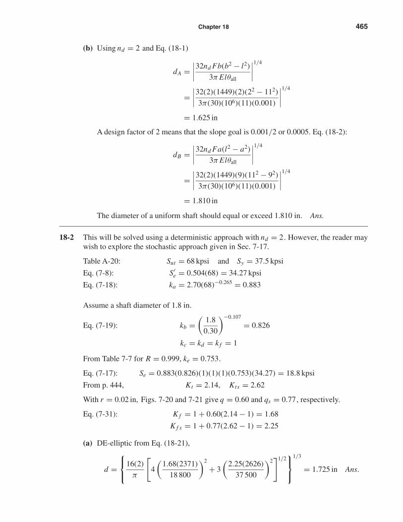
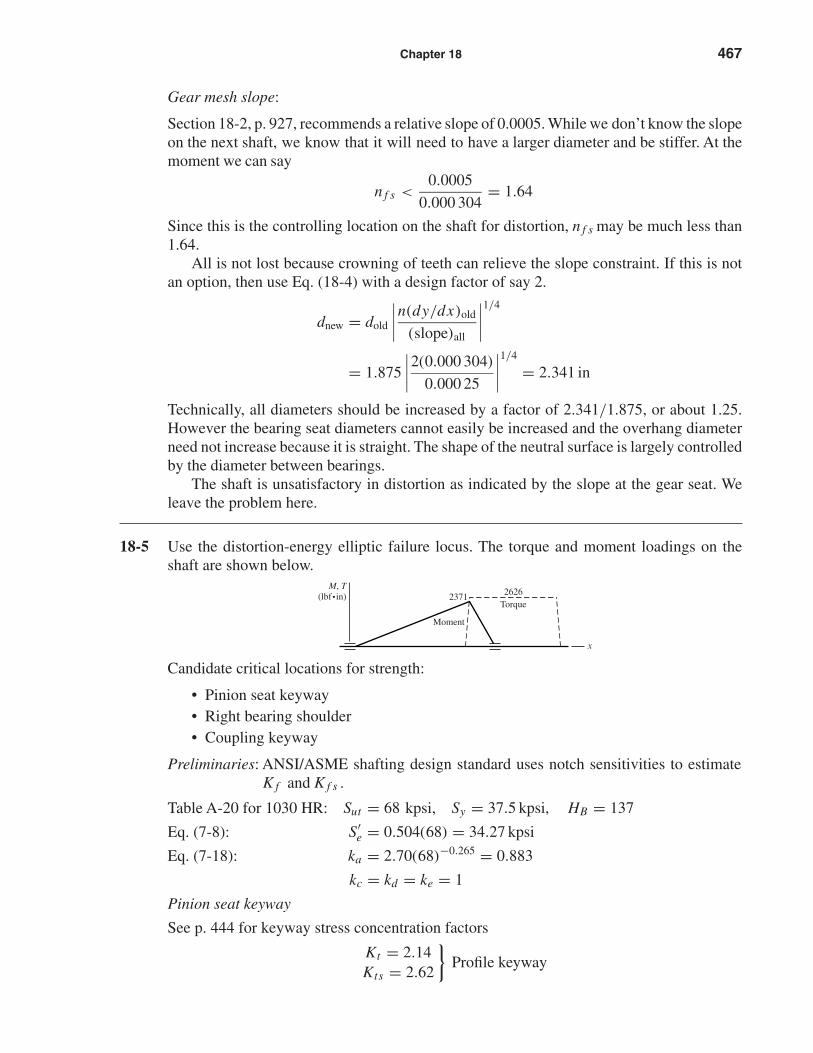
18-5 Use the distortion-energy elliptic failure locus. The torque and moment loadings on theshaft are shown below.
Candidate critical locations for strength:
• Pinion seat keyway• Right bearing shoulder• Coupling keyway
Preliminaries: ANSI/ASME shafting design standard uses notch sensitivities to estimateK f and K f s .
Table A-20 for 1030 HR: Sut = 68 kpsi, Sy = 37.5 kpsi, HB = 137
Eq. (7-8): S′e = 0.504(68) = 34.27 kpsi
Eq. (7-18): ka = 2.70(68)−0.265 = 0.883
kc = kd = ke = 1
Pinion seat keyway
See p. 444 for keyway stress concentration factors
Kt = 2.14Kts = 2.62
}Profile keyway
Moment
M, T(lbf•in)
x
2371 2626Torque
shi20396_ch18.qxd 8/28/03 4:16 PM Page 467
468 Solutions Manual • Instructor’s Solution Manual to Accompany Mechanical Engineering Design
For an end-mill profile keyway cutter of 0.010 in radius,
From Fig. 7-20: q = 0.50
From Fig. 7-21: qs = 0.65
Eq. (7-31):K f s = 1 + qs(Kts − 1)
= 1 + 0.65(2.62 − 1) = 2.05
K f = 1 + 0.50(2.14 − 1) = 1.57
Eq. (18-15):
Eq. (7-19):
A = 2K f Ma = 2(1.57)(2371) = 7445 lbf · in
B =√
3K f sTm =√
3(2.05)(2626) = 9324 lbf · in
r = σ ′a
σ ′m
= A
B= 7445
9324= 0.798
kb =(
1.875
0.30
)−0.107
= 0.822
Eq. (7-17): Se = 0.883(0.822)(0.753)(34.27) = 18.7 kpsi
Eq. (18-22):
1
n= 16
π(1.8753)
{4
[1.57(2371)
18 700
]2
+ 3
[2.05(2626)
37 500
]2}1/2
= 0.363, from which n = 2.76
Table 7-11:
Sa =√
(0.798)2(37.5)2(18.7)2
(0.798)2(37.5)2 + 18.72= 15.9 kpsi
Sm = Sa
r= 15.9
0.798= 19.9 kpsi
rcrit = 15.9
37.5 − 15.9= 0.736 < 0.7
Therefore, the threat lies in fatigue.
Right-hand bearing shoulder
The text does not give minimum and maximum shoulder diameters for 03-series bearings(roller). Use D = 1.75 in.
r
d= 0.030
1.574= 0.019,
D
d= 1.75
1.574= 1.11
From Fig. A-15-9,
Kt = 2.4From Fig. A-15-8,
Kts = 1.6
shi20396_ch18.qxd 8/28/03 4:16 PM Page 468
Chapter 18 469
From Fig. 7-20, q = 0.65
From Fig. 7-21, qs = 0.83
K f = 1 + 0.65(2.4 − 1) = 1.91
K f s = 1 + 0.83(1.6 − 1) = 1.50
M = 2371
(0.453
2
)= 537 lbf · in
Eq. (18-22):
1
n= 16
π(1.5743)
[4
(1.91(537)
18 700
)2
+ 3
(1.50(262)
37 500
)2]1/2
= 0.277, from which n = 3.61
Overhanging coupling keyway
There is no bending moment, thus Eq. (18-22) reduces to:
1
n= 16
√3K f sTm
πd3Sy= 16
√3(1.50)(2626)
π(1.53)(37 500)
= 0.275 from which n = 3.64
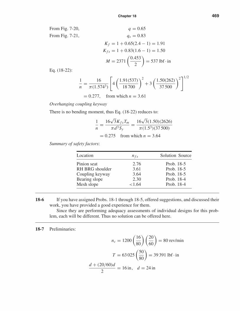
Summary of safety factors:
Location n f s Solution Source
Pinion seat 2.76 Prob. 18-5RH BRG shoulder 3.61 Prob. 18-5Coupling keyway 3.64 Prob. 18-5Bearing slope 2.30 Prob. 18-4Mesh slope <1.64 Prob. 18-4
18-6 If you have assigned Probs. 18-1 through 18-5, offered suggestions, and discussed theirwork, you have provided a good experience for them.
Since they are performing adequacy assessments of individual designs for this prob-lem, each will be different. Thus no solution can be offered here.
18-7 Preliminaries:
nc = 1200
(16
80
)(20
60
)= 80 rev/min
T = 63 025
(50
80
)= 39 391 lbf · in
d + (20/60)d
2= 16 in, d = 24 in
shi20396_ch18.qxd 8/28/03 4:16 PM Page 469
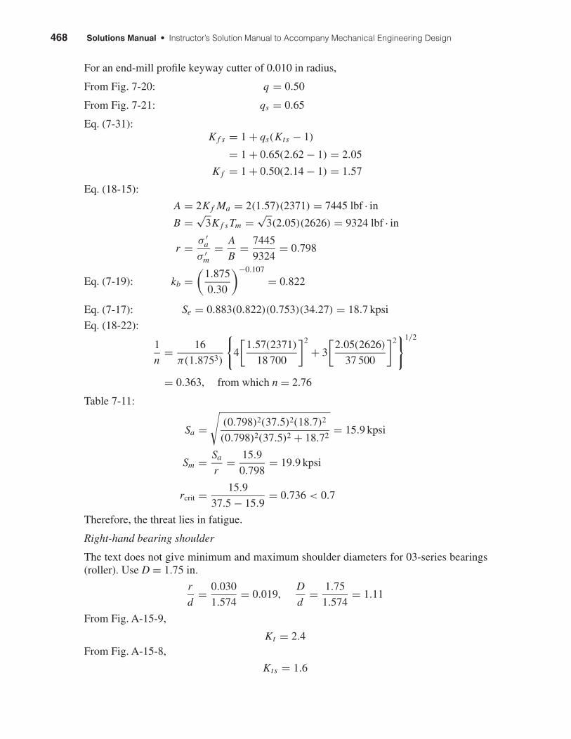
470 Solutions Manual • Instructor’s Solution Manual to Accompany Mechanical Engineering Design
W t = T
d/2= 39 391
12= 3283 lbf
Wr = 3283 tan 25° = 1531 lbf
W = W t
cos 25°= 3283
cos 25°= 3622 lbf
Loads W, R1 and R2 are all in the same plane.
R1 = 3622
(8
11
)= 2634 lbf
R2 = 3622
(3
11
)= 988 lbf
The steepest slope will be at the left bearing.
Eq. (18-1):
d =∣∣∣∣32nd Fb(b2 − l2)
3π Elθall
∣∣∣∣1/4
=∣∣∣∣32(2)(3622)(8)(82 − 112)
3π(30)(106)(11)(0.001)
∣∣∣∣1/4
= 2.414 in
The design should proceed in the same manner as Probs. 18-1 to 18-6.
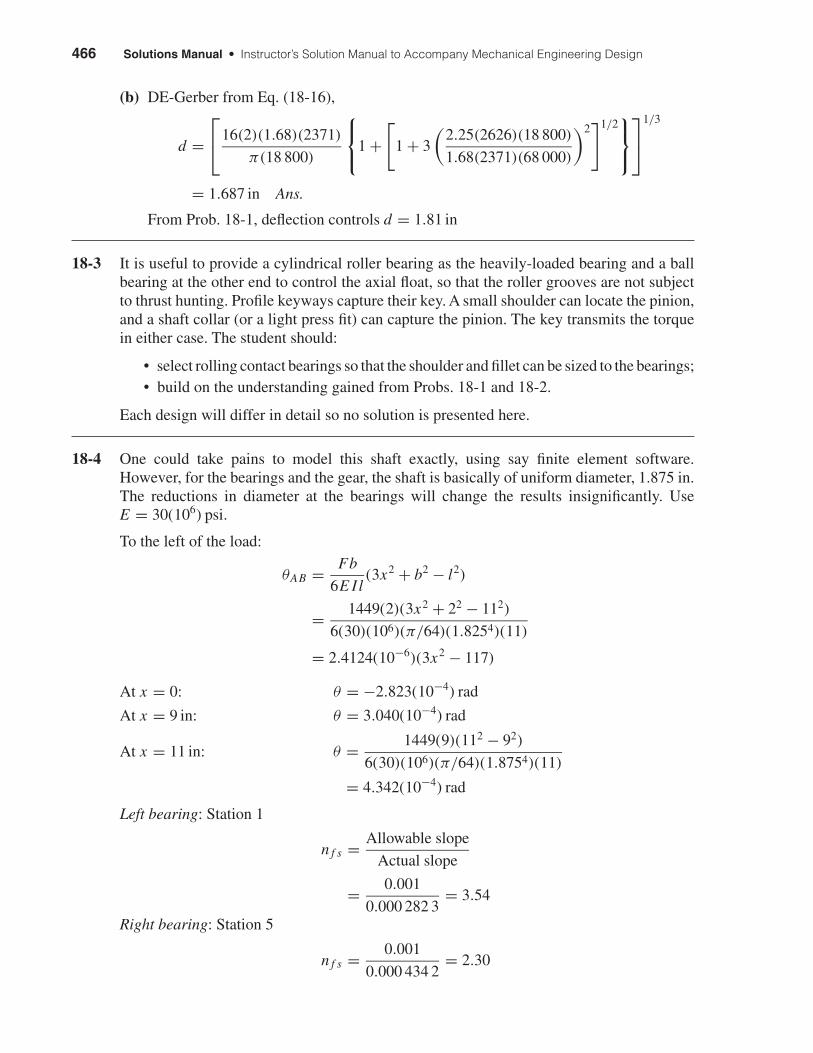
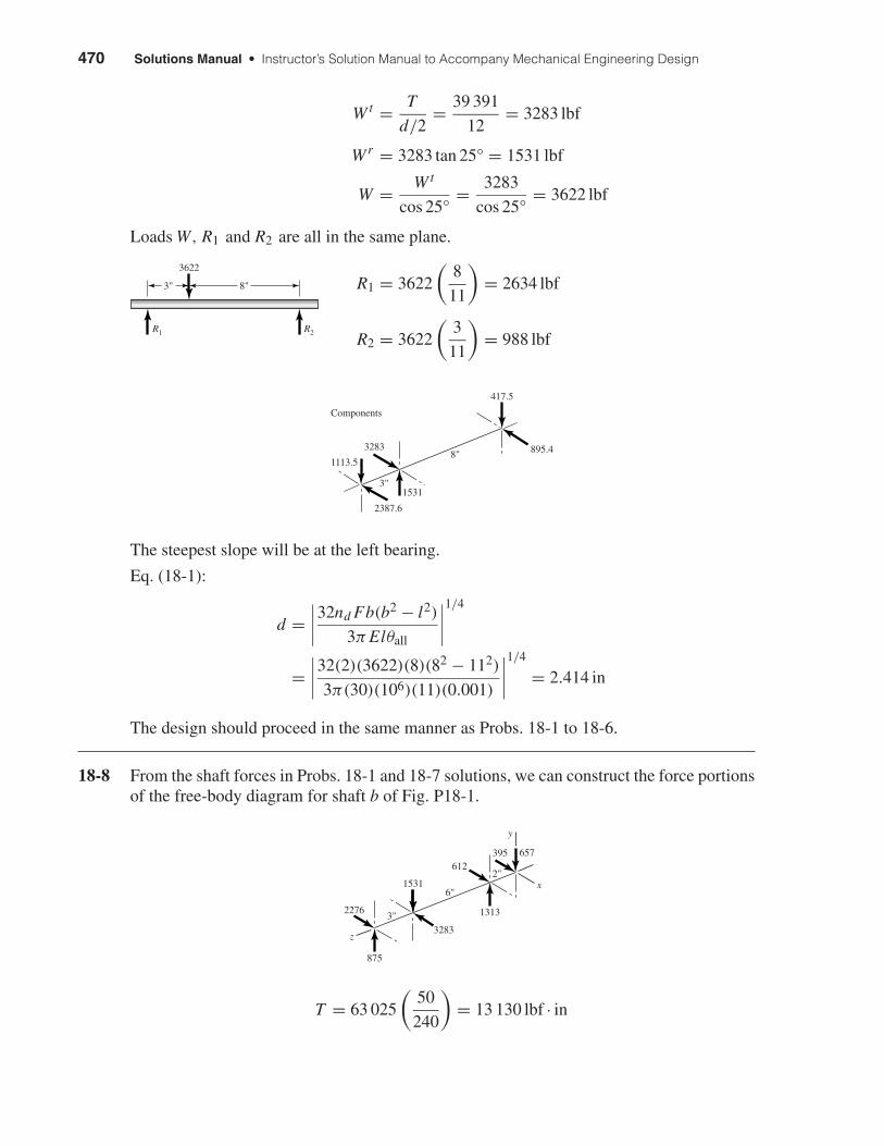
18-8 From the shaft forces in Probs. 18-1 and 18-7 solutions, we can construct the force portionsof the free-body diagram for shaft b of Fig. P18-1.
T = 63 025
(50
240
)= 13 130 lbf · in
3"
6"
2"
875
2276
1531
612395 657
1313
z
y
x
3283
3"
8"
2387.6
417.5
895.43283
Components
1113.5
1531
8"
3622
R1 R2
3"
shi20396_ch18.qxd 8/28/03 4:16 PM Page 470
Chapter 18 471
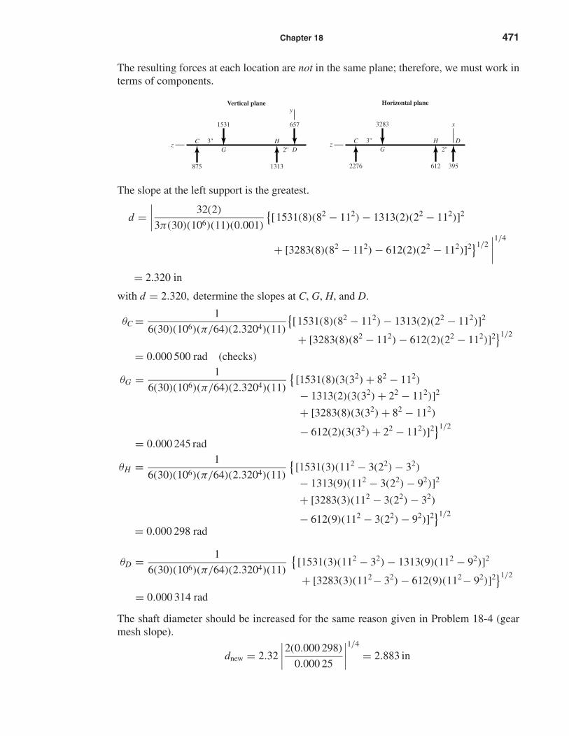
The resulting forces at each location are not in the same plane; therefore, we must work interms of components.
The slope at the left support is the greatest.
d =∣∣∣∣ 32(2)
3π(30)(106)(11)(0.001)
{[1531(8)(82 − 112) − 1313(2)(22 − 112)]2
+ [3283(8)(82 − 112) − 612(2)(22 − 112)]2}1/2∣∣∣∣1/4
= 2.320 in
with d = 2.320, determine the slopes at C, G, H, and D.
θC = 1
6(30)(106)(π/64)(2.3204)(11)
{[1531(8)(82 − 112) − 1313(2)(22 − 112)]2
+ [3283(8)(82 − 112) − 612(2)(22 − 112)]2}1/2
= 0.000 500 rad (checks)
θG = 1
6(30)(106)(π/64)(2.3204)(11)
{[1531(8)(3(32) + 82 − 112)
− 1313(2)(3(32) + 22 − 112)]2
+ [3283(8)(3(32) + 82 − 112)
− 612(2)(3(32) + 22 − 112)]2}1/2
= 0.000 245 rad
θH = 1
6(30)(106)(π/64)(2.3204)(11)
{[1531(3)(112 − 3(22) − 32)
− 1313(9)(112 − 3(22) − 92)]2
+ [3283(3)(112 − 3(22) − 32)
− 612(9)(112 − 3(22) − 92)]2}1/2
= 0.000 298 rad
θD = 1
6(30)(106)(π/64)(2.3204)(11)
{[1531(3)(112 − 32) − 1313(9)(112 − 92)]2
+ [3283(3)(112− 32) − 612(9)(112− 92)]2}1/2
= 0.000 314 rad
The shaft diameter should be increased for the same reason given in Problem 18-4 (gearmesh slope).
dnew = 2.32
∣∣∣∣2(0.000 298)
0.000 25
∣∣∣∣1/4
= 2.883 in
3"
2276 612 395
3283
Horizontal plane
x
2"C
GDH
z3"
875 1313
1531 657
2"z
CG D
H
Vertical planey
shi20396_ch18.qxd 8/28/03 4:16 PM Page 471
472 Solutions Manual • Instructor’s Solution Manual to Accompany Mechanical Engineering Design
Strength constraints
MG = 3√
8752 + 22762 = 7315 lbf · in
MH = 2√
6572 + 3952 = 1533 lbf · in
Point G is more critical. Assume d = 2.88 in.
Similar to Prob. 8-2, Sut = 68 kpsi, Sy = 37.5 kpsi and ka = 0.883
Eq. (7-19): kb = 0.91(2.88)−0.157 = 0.771
kc = kd = k f = 1
For R = 0.995, Table A-10 provides z = 2.576.
Eq. (7-28): ke = 1 − 0.08(2.576) = 0.794
Eq. (7-17): Se = 0.883(0.771)(1)(1)(0.794)(1)(0.504)(68) = 18.5 kpsi
Eq. (7-31): K f = 1.68, K f s = 2.25
Using DE-elliptic theory, Eq. (18-21)
d =16(2)
π
[4
(1.68(7315)
18 500
)2
+ 3
(2.25(13 130)
37 500
)2]1/2
1/3
= 2.687 in O.K.
Students will approach the design differently from this point on.
18-9 The bearing ensemble reliability is related to the six individual reliabilities by
R = R1 R2 R3 R4 R5 R6
For an ensemble reliability of R,the individual reliability goals are
Ri = R1/6
The radial loads at bearings A through F were found to be
A B C D E F
263 1186 2438 767 2634 988 lbf
It may be useful to make the bearings at A, D, and F one size and those at B, C, and E an-other size, to minimize the number of different parts. In such a case
R1 = RB RC RE , R2 = RA RD RF
R = R1 R2 = (RB RC RE )(RA RD RF )
where the reliabilities RA through RF are the reliabilities of Sec. 11-10, Eqs. (11-18), (11-19), (11-20), and (11-21).
A corollary to the bearing reliability description exists and is given as
R = Ra Rb Rc
In this case you can begin withRi = R1/3
shi20396_ch18.qxd 8/28/03 4:16 PM Page 472
Chapter 18 473
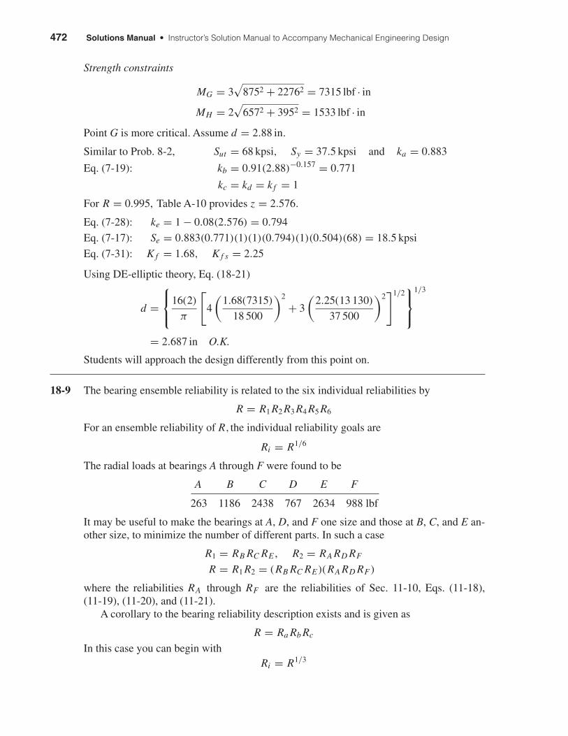
18-10 This problem is not the same as Prob. 11-9, although the figure is the same. We have adesign task of identifying bending moment and torsion diagrams which are preliminary toan industrial roller shaft design.
F yC = 30(8) = 240 lbf
FzC = 0.4(240) = 96 lbf
T = FzC (2) = 96(2) = 192 lbf · in
FzB = T
1.5= 192
1.5= 128 lbf
F yB = Fz
B tan 20° = 128 tan 20° = 46.6 lbf
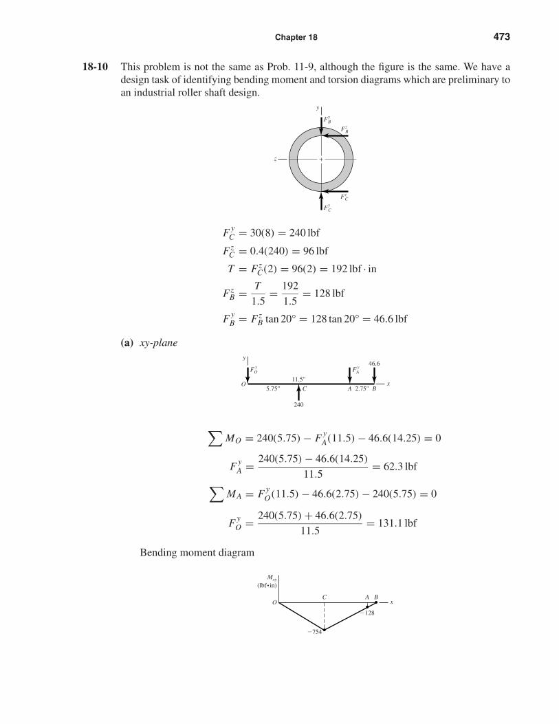
(a) xy-plane
∑MO = 240(5.75) − F y
A(11.5) − 46.6(14.25) = 0
F yA = 240(5.75) − 46.6(14.25)
11.5= 62.3 lbf
∑MA = F y
O(11.5) − 46.6(2.75) − 240(5.75) = 0
F yO = 240(5.75) + 46.6(2.75)
11.5= 131.1 lbf
Bending moment diagram
CO
�754
�128
A B
Mxy
(lbf•in)
x
11.5"
5.75" ACO
FAyFO
y
Bx
y
2.75"
240
46.6
z
y
FyB
FzB
FzC
FyC
shi20396_ch18.qxd 8/28/03 4:17 PM Page 473
474 Solutions Manual • Instructor’s Solution Manual to Accompany Mechanical Engineering Design
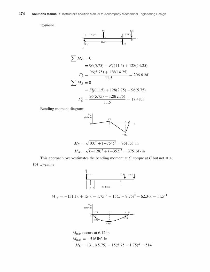
xz-plane
∑MO = 0
= 96(5.75) − FzA(11.5) + 128(14.25)
FzA = 96(5.75) + 128(14.25)
11.5= 206.6 lbf∑
MA = 0
= FzO(11.5) + 128(2.75) − 96(5.75)
FzO = 96(5.75) − 128(2.75)
11.5= 17.4 lbf
Bending moment diagram:
MC =√
1002 + (−754)2 = 761 lbf · in
MA =√
(−128)2 + (−352)2 = 375 lbf · in
This approach over-estimates the bending moment at C, torque at C but not at A.
(b) xy-plane
Mxy = −131.1x + 15〈x − 1.75〉2 − 15〈x − 9.75〉2 − 62.3〈x − 11.5〉1
Mmax occurs at 6.12 in
Mmax = −516 lbf · in
MC = 131.1(5.75) − 15(5.75 − 1.75)2 = 514
C
�514
�128�229
A B1.75O
Mxy
(lbf•in)
x
x
62.3131.1
30 lbf/in
46.6
y
C
100
�352
A BO
Mxz
(lbf•in)
x
11.5"
5.75"C A
FzAFz
O
B
z
2.75"
96 128
O x
shi20396_ch18.qxd 8/28/03 4:17 PM Page 474
Chapter 18 475
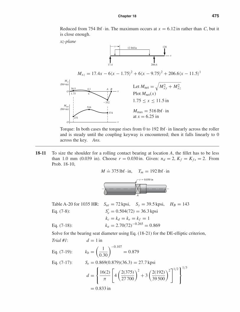
Reduced from 754 lbf · in. The maximum occurs at x = 6.12 in rather than C, but itis close enough.
xz-plane
Mxz = 17.4x − 6〈x − 1.75〉2 + 6〈x − 9.75〉2 + 206.6〈x − 11.5〉1
Let Mnet =√
M2xy + M2
xz
Plot Mnet(x)
1.75 ≤ x ≤ 11.5 in
Mmax = 516 lbf · inat x = 6.25 in
Torque: In both cases the torque rises from 0 to 192 lbf · in linearly across the rollerand is steady until the coupling keyway is encountered; then it falls linearly to 0across the key. Ans.
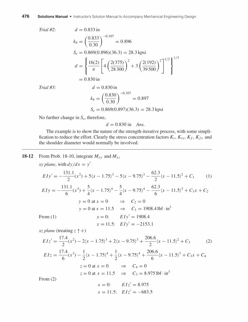
18-11 To size the shoulder for a rolling contact bearing at location A, the fillet has to be lessthan 1.0 mm (0.039 in). Choose r = 0.030 in. Given: nd = 2, K f = K f s = 2. FromProb. 18-10,
M.= 375 lbf · in, Tm = 192 lbf · in
Table A-20 for 1035 HR: Sut = 72 kpsi, Sy = 39.5 kpsi, HB = 143
Eq. (7-8): S′e = 0.504(72) = 36.3 kpsi
kc = kd = ke = k f = 1
Eq. (7-18): ka = 2.70(72)−0.265 = 0.869
Solve for the bearing seat diameter using Eq. (18-21) for the DE-elliptic criterion,
Trial #1: d = 1 in
Eq. (7-19): kb =(
1
0.30
)−0.107
= 0.879
Eq. (7-17): Se = 0.869(0.879)(36.3) = 27.7 kpsi
d =16(2)
π
[4
(2(375)
27 700
)2
+ 3
(2(192)
39 500
)2]1/2
1/3
= 0.833 in
r � 0.030 in
A
C
4.1
516
231
�352
374
O
O
A B
Mnet
(lbf •in)
x
1.75
30.5
Mxz
(lbf•in)
x
206.617.4
x
x
12812 lbf/in
shi20396_ch18.qxd 8/28/03 4:17 PM Page 475
476 Solutions Manual • Instructor’s Solution Manual to Accompany Mechanical Engineering Design
Trial #2: d = 0.833 in
kb =(
0.833
0.30
)−0.107
= 0.896
Se = 0.869(0.896)(36.3) = 28.3 kpsi
d =16(2)
π
[4
(2(375)
28 300
)2
+ 3
(2(192)
39 500
)2]1/2
1/3
= 0.830 in
Trial #3: d = 0.830 in
kb =(
0.830
0.30
)−0.107
= 0.897
Se = 0.869(0.897)(36.3) = 28.3 kpsi
No further change in Se, therefore,
d = 0.830 in Ans.
The example is to show the nature of the strength-iterative process, with some simpli-fication to reduce the effort. Clearly the stress concentration factors Kt , Kts , K f , K f s andthe shoulder diameter would normally be involved.
18-12 From Prob. 18-10, integrate Mxy and Mxz
xy plane, with dy/dx = y′
E I y′ = −131.1
2(x2) + 5〈x − 1.75〉3 − 5〈x − 9.75〉3 − 62.3
2〈x − 11.5〉2 + C1 (1)
E I y = −131.1
6(x3) + 5
4〈x − 1.75〉4 − 5
4〈x − 9.75〉4 − 62.3
6〈x − 11.5〉3 + C1x + C2
y = 0 at x = 0 ⇒ C2 = 0
y = 0 at x = 11.5 ⇒ C1 = 1908.4 lbf · in3
From (1) x = 0: E I y′ = 1908.4
x = 11.5: E I y′ = −2153.1xz plane (treating z ↑+)
E I z′ = 17.4
2(x2) − 2〈x − 1.75〉3 + 2〈x − 9.75〉3 + 206.6
2〈x − 11.5〉2 + C3 (2)
E I z = 17.4
6(x3) − 1
2〈x − 1.75〉4 + 1
2〈x − 9.75〉4 + 206.6
6〈x − 11.5〉3 + C3x + C4
z = 0 at x = 0 ⇒ C4 = 0
z = 0 at x = 11.5 ⇒ C3 = 8.975 lbf · in3
From (2)x = 0: E I z′ = 8.975
x = 11.5: E I z′ = −683.5
shi20396_ch18.qxd 8/28/03 4:17 PM Page 476
Chapter 18 477
At O: E Iθ =√
1908.42 + 8.9752 = 1908.4 lbf · in3
A: E Iθ =√
(−2153.1)2 + (−683.5)2 = 2259 lbf · in3 (dictates size)
With I = (π/64)d4,
d =[
64
π Eθ(2259)
]1/4
=[
64(2259)
π(30)(106)(0.001)
]1/4
= 1.113 in Ans.
For θ = 0.0005 rad
d =(
0.001
0.0005
)1/4
(1.113) = 1.323 in Ans.
18-13 From Prob. 18-12, Eqs. (1) and (2),
At B, x = 14.25": E I y′ = −2328 lbf · in3
E I z′ = −1167 lbf · in3
E Iθ =√
(−2328)2 + (−1167)2 = 2604 lbf · in3
d =[
64(2604)
π(30)(106)(0.0005)
]1/4
= 1.371 in Ans.
With nd = 2
d =(
2
1
)1/4
(1.371) = 1.630 in Ans.
Note: If 0.0005" is divided in the mesh to 0.000 25"/gear then for nd = 1, d = 1.630 inand for nd = 2, d = (2/1)1/4(1.630) = 1.938 in.
18-14 Similar to earlier design task; each design will differ.
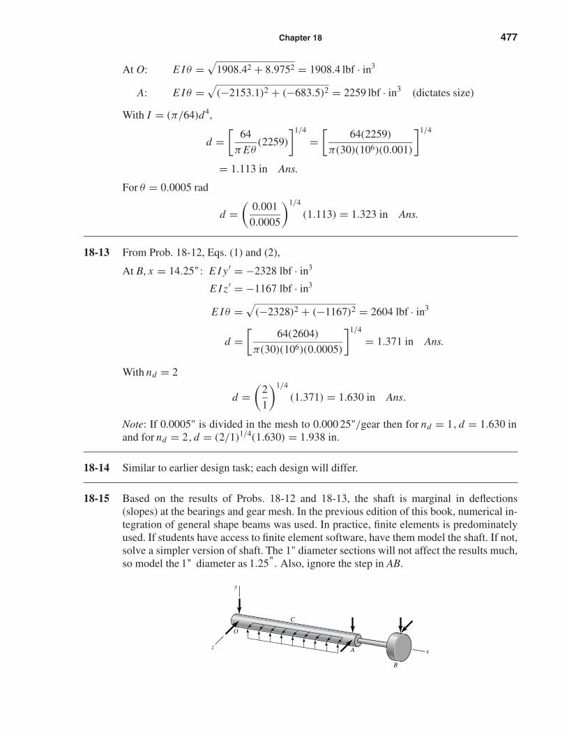
18-15 Based on the results of Probs. 18-12 and 18-13, the shaft is marginal in deflections(slopes) at the bearings and gear mesh. In the previous edition of this book, numerical in-tegration of general shape beams was used. In practice, finite elements is predominatelyused. If students have access to finite element software, have them model the shaft. If not,solve a simpler version of shaft. The 1" diameter sections will not affect the results much,so model the 1" diameter as 1.25". Also, ignore the step in AB.
Azx
y
O
C
B
shi20396_ch18.qxd 8/28/03 4:17 PM Page 477
478 Solutions Manual • Instructor’s Solution Manual to Accompany Mechanical Engineering Design
The deflection equations developed in Prob. 18-12 still apply to section OCA.
O: E Iθ = 1908.4 lbf · in3
A: E Iθ = 2259 lbf · in3 (still dictates)
θ = 2259
30(106)(π/64)(1.254)= 0.000 628 rad
n = 0.001
0.000 628= 1.59
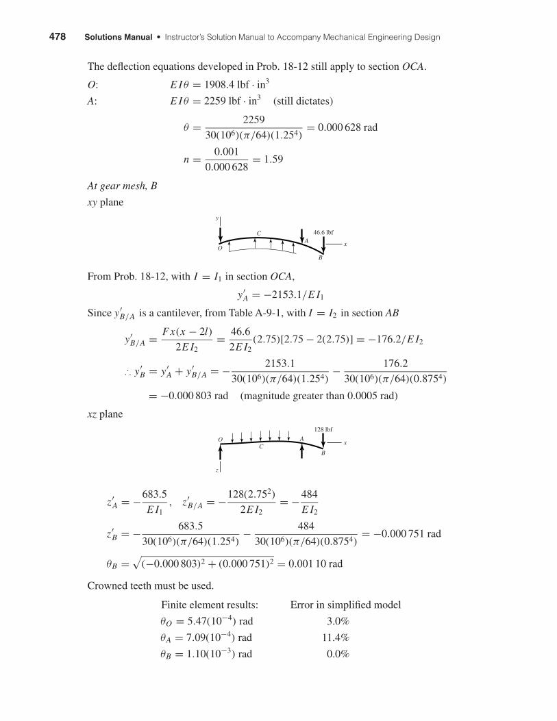
At gear mesh, B
xy plane
From Prob. 18-12, with I = I1 in section OCA,
y′A = −2153.1/E I1
Since y′B/A is a cantilever, from Table A-9-1, with I = I2 in section AB
y′B/A = Fx(x − 2l)
2E I2= 46.6
2E I2(2.75)[2.75 − 2(2.75)] = −176.2/E I2
∴ y′B = y′
A + y′B/A = − 2153.1
30(106)(π/64)(1.254)− 176.2
30(106)(π/64)(0.8754)
= −0.000 803 rad (magnitude greater than 0.0005 rad)
xz plane
z′A = −683.5
E I1, z′
B/A = −128(2.752)
2E I2= −484
E I2
z′B = − 683.5
30(106)(π/64)(1.254)− 484
30(106)(π/64)(0.8754)= −0.000 751 rad
θB =√
(−0.000 803)2 + (0.000 751)2 = 0.001 10 rad
Crowned teeth must be used.
Finite element results: Error in simplified model
θO = 5.47(10−4) rad 3.0%
θA = 7.09(10−4) rad 11.4%
θB = 1.10(10−3) rad 0.0%
z
A
B
x
128 lbf
CO
x
y
A
B
C
O
46.6 lbf
shi20396_ch18.qxd 8/28/03 4:17 PM Page 478
Chapter 18 479
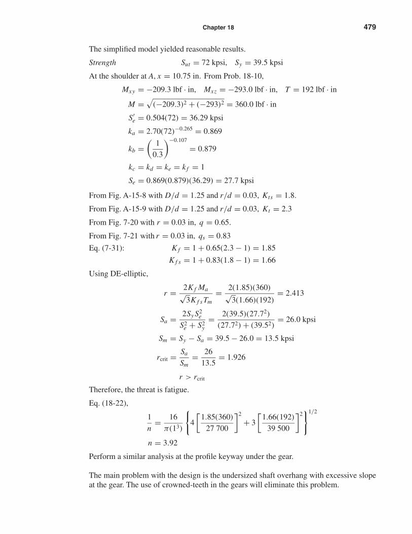
The simplified model yielded reasonable results.
Strength Sut = 72 kpsi, Sy = 39.5 kpsi
At the shoulder at A, x = 10.75 in. From Prob. 18-10,
Mxy = −209.3 lbf · in, Mxz = −293.0 lbf · in, T = 192 lbf · in
M =√
(−209.3)2 + (−293)2 = 360.0 lbf · in
S′e = 0.504(72) = 36.29 kpsi
ka = 2.70(72)−0.265 = 0.869
kb =(
1
0.3
)−0.107
= 0.879
kc = kd = ke = k f = 1
Se = 0.869(0.879)(36.29) = 27.7 kpsi
From Fig. A-15-8 with D/d = 1.25 and r/d = 0.03, Kts = 1.8.
From Fig. A-15-9 with D/d = 1.25 and r/d = 0.03, Kt = 2.3
From Fig. 7-20 with r = 0.03 in, q = 0.65.
From Fig. 7-21 with r = 0.03 in, qs = 0.83
Eq. (7-31): K f = 1 + 0.65(2.3 − 1) = 1.85
K f s = 1 + 0.83(1.8 − 1) = 1.66
Using DE-elliptic,
r = 2K f Ma√3K f sTm
= 2(1.85)(360)√3(1.66)(192)
= 2.413
Sa = 2Sy S2e
S2e + S2
y= 2(39.5)(27.72)
(27.72) + (39.52)= 26.0 kpsi
Sm = Sy − Sa = 39.5 − 26.0 = 13.5 kpsi
rcrit = Sa
Sm= 26
13.5= 1.926
r > rcrit
Therefore, the threat is fatigue.
Eq. (18-22),
1
n= 16
π(13)
{4
[1.85(360)
27 700
]2
+ 3
[1.66(192)
39 500
]2}1/2
n = 3.92
Perform a similar analysis at the profile keyway under the gear.
The main problem with the design is the undersized shaft overhang with excessive slopeat the gear. The use of crowned-teeth in the gears will eliminate this problem.
shi20396_ch18.qxd 8/28/03 4:17 PM Page 479
480 Solutions Manual • Instructor’s Solution Manual to Accompany Mechanical Engineering Design
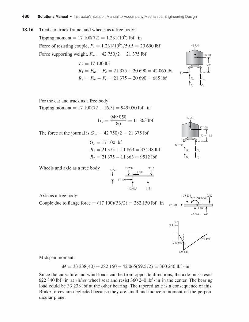
18-16 Treat car, truck frame, and wheels as a free body:
Tipping moment = 17 100(72) = 1.231(106) lbf · in
Force of resisting couple, Fc = 1.231(106)/59.5 = 20 690 lbf
Force supporting weight, Fw = 42 750/2 = 21 375 lbf
Fr = 17 100 lbf
R1 = Fw + Fc = 21 375 + 20 690 = 42 065 lbf
R2 = Fw − Fc = 21 375 − 20 690 = 685 lbf
For the car and truck as a free body:
Tipping moment = 17 100(72 − 16.5) = 949 050 lbf · in
Gc = 949 050
80= 11 863 lbf
The force at the journal is Gw = 42 750/2 = 21 375 lbf
Gr = 17 100 lbf
R1 = 21 375 + 11 863 = 33 238 lbf
R2 = 21 375 − 11 863 = 9512 lbf
Wheels and axle as a free body
Axle as a free body:
Couple due to flange force = (17 100)(33/2) = 282 150 lbf · in
Midspan moment:
M = 33 238(40) + 282 150 − 42 065(59.5/2) = 360 240 lbf · in
Since the curvature and wind loads can be from opposite directions, the axle must resist622 840 lbf · in at either wheel seat and resist 360 240 lbf · in in the center. The bearingload could be 33 238 lbf at the other bearing. The tapered axle is a consequence of this.Brake forces are neglected because they are small and induce a moment on the perpen-dicular plane.
340 690
M(lbf•in)
622 840
97 498
17 10017 100
33 238
42 065 685
9512282 150 lbf•in
17 100
17 10033�2
33 238
42 065 685
9512
Gw
Gr
Gw
Gc Gc
72 � 16.5
42 750
17 100
Fw
Fr
Fw
Fc Fc
72"
42 750
17 100
shi20396_ch18.qxd 8/28/03 4:17 PM Page 480
Chapter 18 481
18-17 Some information is brought forward from the solution of Prob. 18-16. At the wheel seat
σ ′ = 32M
πd3= 32(622 840)
π(73)= 18 496 psi
At mid-axle
σ ′ = 32(360 240)
π(5.375)3= 23 630 psi
The stress at the wheel seat consists of the bending stress plus the shrink fit compressioncombining for a higher von Mises stress.
18-18 This problem has to be done by successive trials, since Se is a function of shaft size inEq. (18-21). The material is SAE 2340 for which Sut = 1226 MPa, Sy = 1130 MPa, andHB ≥ 368.
Eq. (7-18): ka = 4.51(1226)−0.265 = 0.685
Trial #1: Choose dr = 22 mm
kb =(
22
7.62
)−0.107
= 0.893
Se = 0.685(0.893)(0.504)(1226) = 378 MPa
dr = d − 2r = 0.75D − 2D/20 = 0.65D
D = dr
0.65= 22
0.65= 33.8 mm
r = D
20= 33.8
20= 1.69 mm
Fig. A-15-14:
d = dr + 2r = 22 + 2(1.69) = 25.4 mm
d
dr= 25.4
22= 1.15
r
dr= 1.69
22= 0.077
Kt = 1.9
Fig. A-15-15: Kts = 1.5
Fig. 7-20: r = 1.69 mm, q = 0.90
Fig. 7-21: r = 1.69 mm, qs = 0.97
Eq. (7-31): K f = 1 + 0.90(1.9 − 1) = 1.81
K f s = 1 + 0.97(1.5 − 1) = 1.49
shi20396_ch18.qxd 8/28/03 4:17 PM Page 481
482 Solutions Manual • Instructor’s Solution Manual to Accompany Mechanical Engineering Design
Eq. (18-21) with d as dr ,
dr =16(2.5)
π
[4
(1.81(70)(103)
378
)2
+ 3
(1.49(45)(103)
1130
)2]1/2
1/3
= 20.5 mm
Trial #2: Choose dr = 20.5 mm
kb =(
20.5
7.62
)−0.107
= 0.900
Se = 0.685(0.900)(0.504)(1226) = 381 MPa
D = dr
0.65= 20.5
0.65= 31.5 mm
r = D
20= 31.5
20= 1.58 mm
Figs. A-15-14 and A-15-15:
d = dr + 2r = 20.5 + 2(1.58) = 23.7 mm
d
dr= 23.7
20.5= 1.16
r
dr= 1.58
20.5= 0.077
We are at the limit of readability of the figures so
Kt = 1.9, Kts = 1.5 q = 0.9, qs = 0.97
∴ K f = 1.81 K f s = 1.49
Using Eq. (18-21) produces no changes. Therefore we are done.
Decisions:
dr = 20.5
D = 20.5
0.65= 31.5 mm, d = 0.75(31.5) = 23.6 mm
Use D = 32 mm, d = 24 mm, r = 1.6 mm Ans.
18-19 Refer to Prob. 18-18. Trial #1, nd = 2.5, dr = 22 mm, Se = 378 MPa, K f = 1.81,K f s = 1.49
Eq. (18-30)
dr =32(2.5)
π
[(1.81
70(103)
(378)
)2
+(
1.4945(103)
(1130)
)2]1/2
1/3
= 20.5 mm
shi20396_ch18.qxd 8/28/03 4:17 PM Page 482
Chapter 18 483
Referring to Trial #2 of Prob. 18-18, dr = 20.5 mm and Se = 381 MPa. Substitution intoEq. (18-30) yields dr = 20.5 mm again. Solution is the same as Prob. 18-18; therefore use
D = 32 mm, d = 24 mm, r = 1.6 mm Ans.
18-20 F cos 20°(d/2) = T , F = 2T/(d cos 20°) = 2(3000)/(6 cos 20°) = 1064 lbf
MC = 1064(4) = 4257 lbf · in
(a) Static analysis using fatigue stress concentration factors and Eq. (6-45):
d ={
16n
π Sy
[4(K f M)2 + 3(K f sT )2]1/2
}1/3
={
16(2.5)
π(60 000)
[4(1.8)(4257)2 + 3(1.3)(3000)2]1/2
}1/3
= 1.526 in Ans.
(b) ka = 2.70(80)−0.265 = 0.845
Assume d = 2.00 in
kb =(
2
0.3
)−0.107
= 0.816
Se = 0.845(0.816)(0.504)(80) = 27.8 kpsi
(1) DE-Gerber, Eq. (18-16):
d =16(2.5)(1.8)(4257)
π(27 800)
1 +
{1 + 3
(1.3(3000)(27 800)
1.8(4257)(80 000)
)2}1/2
1/3
= 1.929 in
Revising kb results in d = 1.927 in Ans.
(2) DE-elliptic using d = 2 in for Se with Eq. (18-21),
d =16(2.5)
π
[4
(1.8(4257)
27 800
)2
+ 3
(1.3(3000)
60 000
)2]1/2
1/3
= 1.927 in
Revising kb results in d = 1.926 in Ans.
(3) Soderberg, Eq. (18-30):
d =32(2.5)
π
[(1.8
4257
27 800
)2
+(
1.33000
60 000
)2]1/2
1/3
= 1.932 in
Revising kb results in d = 1.930 in Ans.
(4) DE-Goodman, Eq. (18-34):
d ={
16(2.5)
π
[2
(1.8(4257)
27 800
)+
√3
(1.3(3000)
80 000
)]}1/3
= 2.008 in Ans.
shi20396_ch18.qxd 8/28/03 4:17 PM Page 483
484 Solutions Manual • Instructor’s Solution Manual to Accompany Mechanical Engineering Design
18-21 (a) DE-Gerber, Eqs. (18-13) and (18-15):
A = {4[2.2(600)]2 + 3[1.8(400)]2}1/2 = 2920 lbf · in
B = {4[2.2(500)]2 + 3[1.8(300)]2}1/2 = 2391 lbf · in
d =8(2)(2920)
π(30 000)
1 +
(1 +
[2(2391)(30 000)
2920(100 000)
]2)1/2
1/3
= 1.016 in Ans.
(b) DE-elliptic, Equation prior to Eq. (18-19):
d =(
16n
π
√A2
S2e
+ B2
S2y
)1/3
=16(2)
π
√(2920
30 000
)2
+(
2391
80 000
)2
1/3
= 1.012 in Ans.
(c) MSS-Soderberg, Eq. (18-28):
d =32(2)
π
[2.22
(500
80 000+ 600
30 000
)2
+ 1.82(
300
80 000+ 400
30 000
)2]1/2
1/3
= 1.101 in Ans.
(d) DE-Goodman: Eq. (18-32) can be shown to be
d =[
16n
π
(A
Se+ B
Sut
)]1/3
=[
16(2)
π
(2920
30 000+ 2391
100 000
)]1/3
= 1.073 in
Criterion d (in) Compared to DE-Gerber
DE-Gerber 1.016DE-elliptic 1.012 0.4% lower less conservativeMSS-Soderberg 1.101 8.4% higher more conservativeDE-Goodman 1.073 5.6% higher more conservative
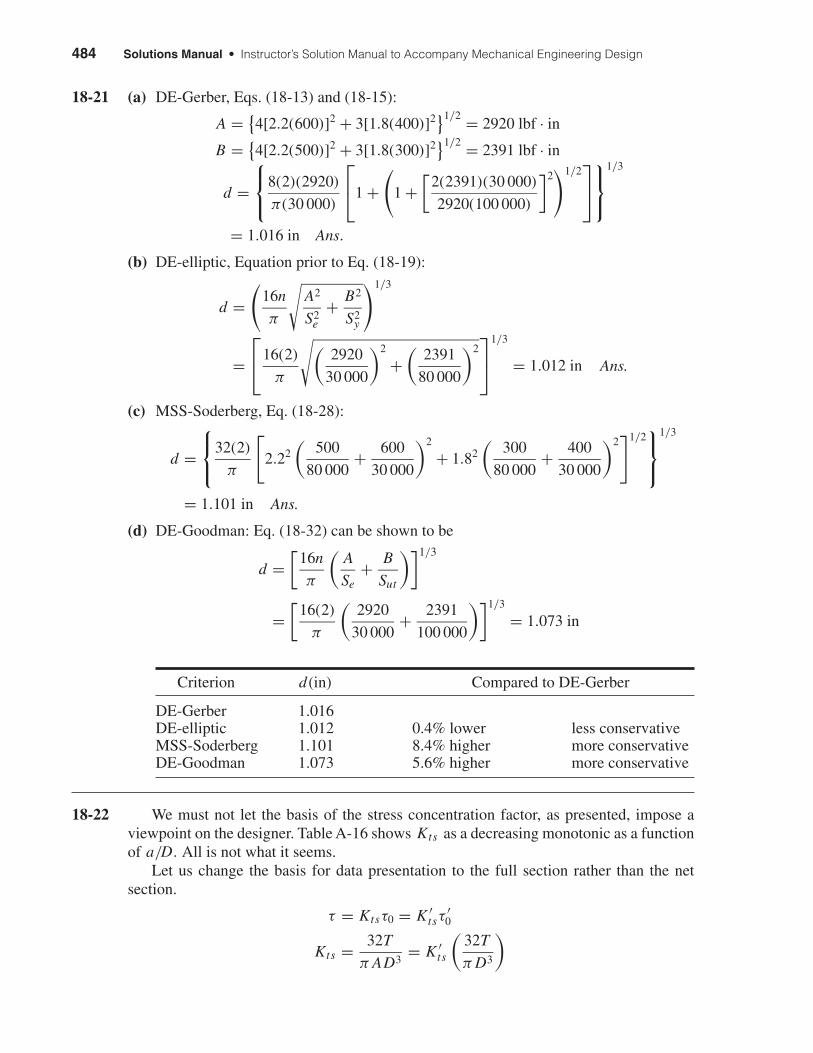
18-22 We must not let the basis of the stress concentration factor, as presented, impose aviewpoint on the designer. Table A-16 shows Kts as a decreasing monotonic as a functionof a/D. All is not what it seems.
Let us change the basis for data presentation to the full section rather than the netsection.
τ = Ktsτ0 = K ′tsτ
′0
Kts = 32T
π AD3= K ′
ts
(32T
π D3
)
shi20396_ch18.qxd 8/28/03 4:17 PM Page 484
Chapter 18 485
Therefore
K ′ts = Kts
A
Form a table:
(a/D) A Kts K ′ts
0.050 0.95 1.77 1.860.075 0.93 1.71 1.840.100 0.92 1.68 1.83 ← minimum0.125 0.89 1.64 1.840.150 0.87 1.62 1.860.175 0.85 1.60 1.880.200 0.83 1.58 1.90
K ′ts has the following attributes:
• It exhibits a minimum;
• It changes little over a wide range;
• Its minimum is a stationary point minimum at a/D.= 0.100;
• Our knowledge of the minima location is
0.075 ≤ (a/D) ≤ 0.125
We can form a design rule: in torsion, the pin diameter should be about 1/10 of the shaftdiameter, for greatest shaft capacity. However, it is not catastrophic if one forgets the rule.
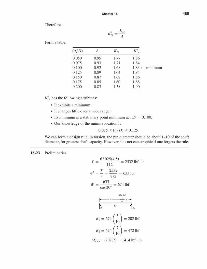
18-23 Preliminaries:
T = 63 025(4.5)
112= 2532 lbf · in
W t = T
r= 2532
8/2= 633 lbf
W = 633
cos 20°= 674 lbf
R1 = 674
(3
10
)= 202 lbf
R2 = 674
(7
10
)= 472 lbf
Mmax = 202(7) = 1414 lbf · in
R1 R2
674 lbf
7" 3"
10"
shi20396_ch18.qxd 8/28/03 4:17 PM Page 485
486 Solutions Manual • Instructor’s Solution Manual to Accompany Mechanical Engineering Design
Is the task strength-controlled or distortion-controlled? With regards to distortion usen = 2 in Eq. (18-1):
dL =∣∣∣∣32(2)(674)(3)(32 − 102)
3π(30)(106)(10)(0.001)
∣∣∣∣1/4
= 1.43 in
Eq. (18-2):
dR =∣∣∣∣32(2)(674)(7)(102 − 72)
3π(30)(106)(10)(0.001)
∣∣∣∣1/4
= 1.53 in
For the gearset, use θAB developed in Prob. 18-4 solution. To the left of the load,
θAB = Fb
6E Il(3x2 + b2 − l2)
Incorporating I = πd4/64 and nd ,
d =∣∣∣∣ 32nd Fb
3π Elθall(3x2 + b2 − l2)
∣∣∣∣1/4
At the gearset, x = 7 with θall = 0.000 25 (apportioning gearmesh slope equally).
d ≤∣∣∣∣32(2)(674)(3)[3(72) + 32 − 102]
3π(30)(106)(10)(0.000 25)
∣∣∣∣1/4
≤ 1.789 in
Since 1.789 > 1.75 in, angular deflection of the matching gear should be less than 0.000 25 rad. Crowned gears should thus be used, or nd scutinized for reduction.
Concerning strength: For K f.= 2, K f s
.= 1.5, Se.= Sut/4, Sy
.= Sut/2 in Eq. (18-1):
d3 = 16n
π
{4
[2(1414)
Sut/4
]2
+ 3
[1.5(2532)
Sut/2
]2}1/2
Solving for Sut and using n = 2 and d = 1.75 in
Sut = 16(2)
π(1.753){4[4(2)(1414)]2 + 3[2(1.5)(2532)]2}1/2 = 49 740 psi
This gives an approximate idea of the shaft material strength necessary and helps identifyan initial material.
With this perspective students can begin.
18-24 This task is a change of pace. Let s be the scale factor of the model, and subscript mdenote ‘model.’
lm = sl
σ = Mc
I, σm = σ
Mm = σm Im
cm= σ s4 I
sc= s3M Ans.
shi20396_ch18.qxd 8/28/03 4:17 PM Page 486
Chapter 18 487
The load that causes bending is related to reaction and distance.
Mm = Rmam = Fmbmam
lm
Solving for Fm gives
Fm = Mmlm
ambm= s3M(sl)
(sa)(sb)= s2 F Ans.
For deflection use Table A-9-6 for section AB,
ym = Fmbm xm
6Em Imlm
(x2
m + b2m − l2
m
)= (s2 F)(sb)(sx)
6E(s4 I )(sl)(s2x2 + s2b2 − s2l2)
= sy Ans. (as expected)
For section BC, the same is expected.
For slope, consider section AB
y′AB = θAB = Fb
6E Il(3x2 + b2 − l2)
θm = s2 F(sb)
6E(s4 I )(sl)(3s2x2 + s2b2 − s2l2) = θ
The same will apply to section BC
Summary:
Slope: y′m = y′
Deflection: ym = sy = y
2
Moment: Mm = s3M = M
8
Force: Fm = s2 F = F
4
These relations are applicable for identical materials and stress levels.
18-25 If you have a finite element program available, it is highly recommended. Beam deflec-tion programs can be implemented but this is time consuming and the programs havenarrow applications. Here we will demonstrate how the problem can be simplified andsolved using singularity functions.
Deflection: First we will ignore the steps near the bearings where the bending momentsare low. Thus let the 30 mm dia. be 35 mm. Secondly, the 55 mm dia. is very thin, 10 mm.The full bending stresses will not develop at the outer fibers so full stiffness will notdevelop either. Thus, ignore this step and let the diameter be 45 mm.
shi20396_ch18.qxd 8/28/03 4:17 PM Page 487
488 Solutions Manual • Instructor’s Solution Manual to Accompany Mechanical Engineering Design
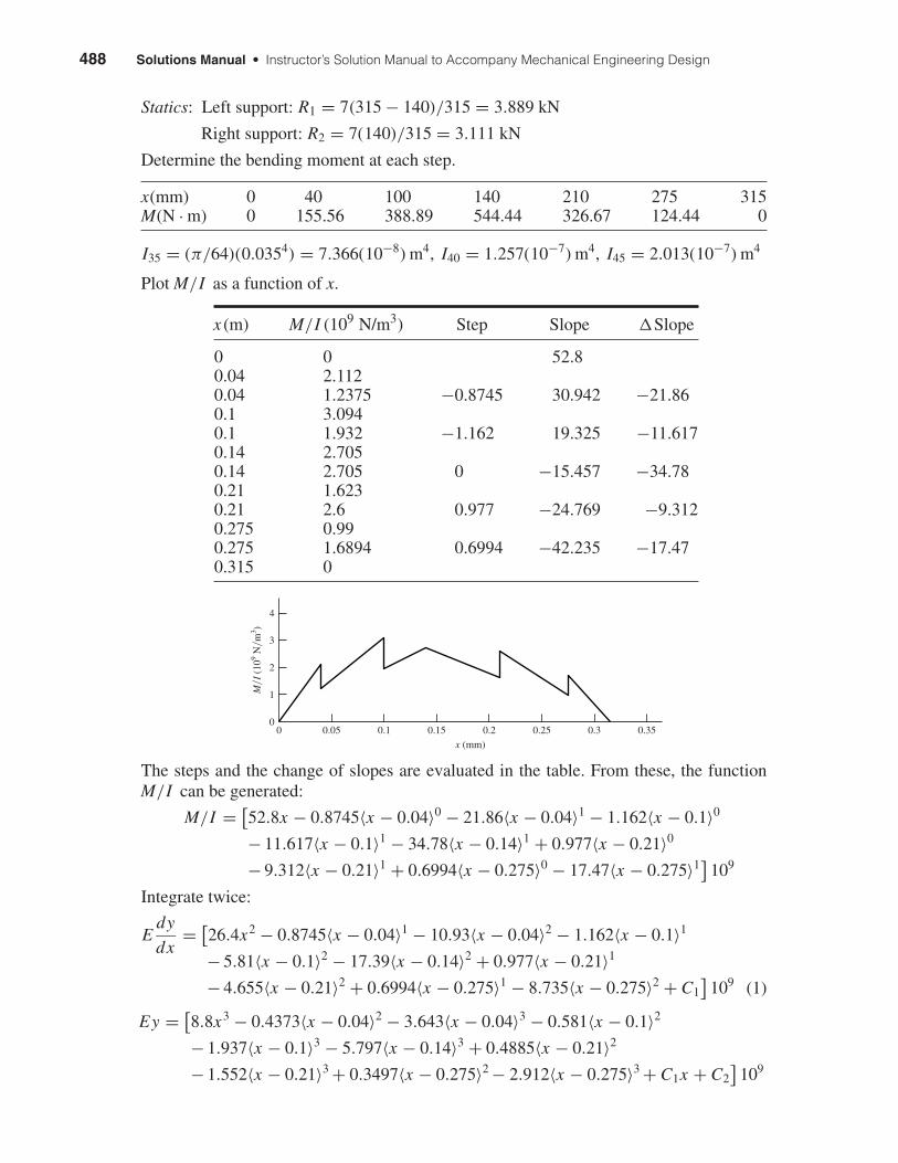
Statics: Left support: R1 = 7(315 − 140)/315 = 3.889 kN
Right support: R2 = 7(140)/315 = 3.111 kN
Determine the bending moment at each step.
x(mm) 0 40 100 140 210 275 315M(N · m) 0 155.56 388.89 544.44 326.67 124.44 0
I35 = (π/64)(0.0354) = 7.366(10−8) m4, I40 = 1.257(10−7) m4, I45 = 2.013(10−7) m4
Plot M/I as a function of x.
x(m) M/I (109 N/m3) Step Slope �Slope
0 0 52.80.04 2.1120.04 1.2375 −0.8745 30.942 −21.860.1 3.0940.1 1.932 −1.162 19.325 −11.6170.14 2.7050.14 2.705 0 −15.457 −34.780.21 1.6230.21 2.6 0.977 −24.769 −9.3120.275 0.990.275 1.6894 0.6994 −42.235 −17.470.315 0
The steps and the change of slopes are evaluated in the table. From these, the functionM/I can be generated:
M/I = [52.8x − 0.8745〈x − 0.04〉0 − 21.86〈x − 0.04〉1 − 1.162〈x − 0.1〉0
− 11.617〈x − 0.1〉1 − 34.78〈x − 0.14〉1 + 0.977〈x − 0.21〉0
− 9.312〈x − 0.21〉1 + 0.6994〈x − 0.275〉0 − 17.47〈x − 0.275〉1] 109
Integrate twice:
Edy
dx= [
26.4x2 − 0.8745〈x − 0.04〉1 − 10.93〈x − 0.04〉2 − 1.162〈x − 0.1〉1
− 5.81〈x − 0.1〉2 − 17.39〈x − 0.14〉2 + 0.977〈x − 0.21〉1
− 4.655〈x − 0.21〉2 + 0.6994〈x − 0.275〉1 − 8.735〈x − 0.275〉2 + C1]
109 (1)
Ey = [8.8x3 − 0.4373〈x − 0.04〉2 − 3.643〈x − 0.04〉3 − 0.581〈x − 0.1〉2
− 1.937〈x − 0.1〉3 − 5.797〈x − 0.14〉3 + 0.4885〈x − 0.21〉2
− 1.552〈x − 0.21〉3 + 0.3497〈x − 0.275〉2 − 2.912〈x − 0.275〉3 + C1x + C2]
109
4
0
1
2
3
0 0.350.30.250.20.15
x (mm)
M�I
(10
9 N�m
3 )
0.10.05
shi20396_ch18.qxd 8/28/03 4:17 PM Page 488
Chapter 18 489
Boundary conditions: y = 0 at x = 0 yields C2 = 0;y = 0 at x = 0.315 m yields C1 = −0.295 25 N/m2.
Equation (1) with C1 = −0.295 25 provides the slopes at the bearings and gear. Thefollowing table gives the results in the second column. The third column gives the resultsfrom a similar finite element model. The fourth column gives the result of a full modelwhich models the 35 and 55 mm diameter steps.
x (mm) θ (rad) F.E. Model Full F.E. Model
0 −0.001 4260 −0.001 4270 −0.001 4160140 −0.000 1466 −0.000 1467 −0.000 1646315 0.001 3120 0.001 3280 0.001 3150
The main discrepancy between the results is at the gear location (x = 140 mm) . Thelarger value in the full model is caused by the stiffer 55 mm diameter step. As was statedearlier, this step is not as stiff as modeling implicates, so the exact answer is somewherebetween the full model and the simplified model which in any event is a small value. Asexpected, modeling the 30 mm dia. as 35 mm does not affect the results much.
It can be seen that the allowable slopes at the bearings are exceeded. Thus, either theload has to be reduced or the shaft “beefed” up. If the allowable slope is 0.001 rad, thenthe maximum load should be Fmax = (0.001/0.001 46)7 = 4.79 kN. With a design factorthis would be reduced further.
To increase the stiffness of the shaft, increase the diameters by (0.001 46/0.001)1/4 =1.097. Form a table:
Old d, mm 20.00 30.00 35.00 40.00 45.00 55.00New ideal d, mm 21.95 32.92 38.41 43.89 49.38 60.35Rounded up d, mm 22.00 34.00 40.00 44.00 50.00 62.00
Repeating the full finite element model results in
x = 0: θ = −9.30 × 10⁻⁴ rad
x = 140 mm: θ = −1.09 × 10⁻⁴ rad
x = 315 mm: θ = 8.65 × 10⁻⁴ rad
Well within our goal. Have the students try a goal of 0.0005 rad at the bearings.
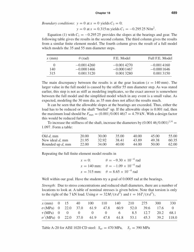
Strength: Due to stress concentrations and reduced shaft diameters, there are a number oflocations to look at. A table of nominal stresses is given below. Note that torsion is onlyto the right of the 7 kN load. Using σ = 32M/(πd3) and τ = 16T/(πd3) ,
x (mm) 0 15 40 100 110 140 210 275 300 330σ (MPa) 0 22.0 37.0 61.9 47.8 60.9 52.0 39.6 17.6 0τ (MPa) 0 0 0 0 0 6 8.5 12.7 20.2 68.1σ ′ (MPa) 0 22.0 37.0 61.9 47.8 61.8 53.1 45.3 39.2 118.0
Table A-20 for AISI 1020 CD steel: Sut = 470 MPa, Sy = 390 MPa
shi20396_ch18.qxd 8/28/03 4:17 PM Page 489
490 Solutions Manual • Instructor’s Solution Manual to Accompany Mechanical Engineering Design
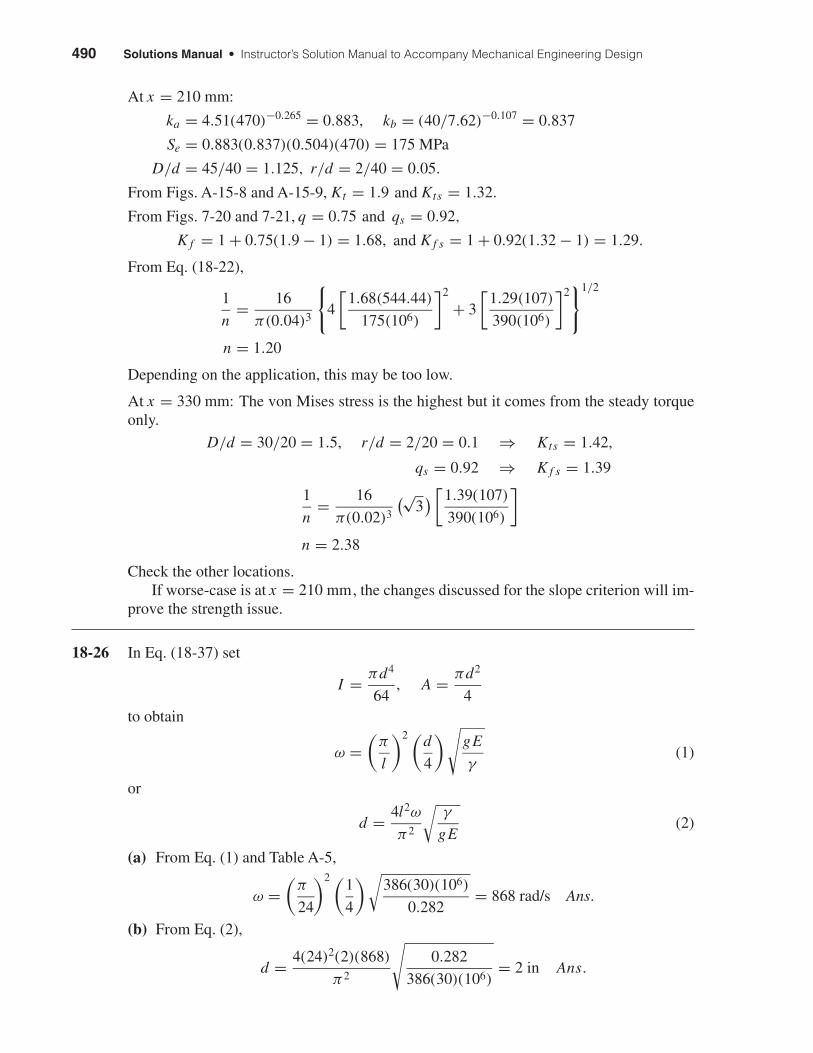
At x = 210 mm:
ka = 4.51(470)−0.265 = 0.883, kb = (40/7.62)−0.107 = 0.837
Se = 0.883(0.837)(0.504)(470) = 175 MPa
D/d = 45/40 = 1.125, r/d = 2/40 = 0.05.
From Figs. A-15-8 and A-15-9, Kt = 1.9 and Kts = 1.32.
From Figs. 7-20 and 7-21, q = 0.75 and qs = 0.92,
K f = 1 + 0.75(1.9 − 1) = 1.68, and K f s = 1 + 0.92(1.32 − 1) = 1.29.
From Eq. (18-22),
1
n= 16
π(0.04)3
{4
[1.68(544.44)
175(106)
]2
+ 3
[1.29(107)
390(106)
]2}1/2
n = 1.20
Depending on the application, this may be too low.
At x = 330 mm: The von Mises stress is the highest but it comes from the steady torqueonly.
D/d = 30/20 = 1.5, r/d = 2/20 = 0.1 ⇒ Kts = 1.42,
qs = 0.92 ⇒ K f s = 1.39
1
n= 16
π(0.02)3
(√3) [
1.39(107)
390(106)
]
n = 2.38
Check the other locations.If worse-case is at x = 210 mm, the changes discussed for the slope criterion will im-
prove the strength issue.
18-26 In Eq. (18-37) set
I = πd4
64, A = πd2
4to obtain
ω =(
π
l
)2 (d
4
)√gE
γ(1)
or
d = 4l2ω
π2
√γ
gE(2)
(a) From Eq. (1) and Table A-5,
ω =(
π
24
)2 (1
4
)√386(30)(106)
0.282= 868 rad/s Ans.
(b) From Eq. (2),
d = 4(24)2(2)(868)
π2
√0.282
386(30)(106)= 2 in Ans.
shi20396_ch18.qxd 8/28/03 4:17 PM Page 490
Chapter 18 491
(c) From Eq. (2),
lω = π2
4
d
l
√gE
γ
Since d/ l is the same regardless of the scale.
lω = constant = 24(868) = 20 832
ω = 20 832
12= 1736 rad/s Ans.
Thus the first critical speed doubles.
18-27 From Prob. 18-26, ω = 868 rad/s
A = 0.7854 in2, I = 0.04909 in4, γ = 0.282 lbf/in3 ,
E = 30(106) psi, w = Aγ l = 0.7854(0.282)(24) = 5.316 lbf
One element:
Eq. (18-37) δ11 = 12(12)(242 − 122 − 122)
6(30)(106)(0.049 09)(24)= 1.956(10−4) in/lbf
y1 = w1δ11 = 5.316(1.956)(10−4) = 1.0398(10−3) in
y21 = 1.0812(10−6)∑
wy = 5.316(1.0398)(10−3) = 5.528(10−3)∑wy2 = 5.316(1.0812)(10−6) = 5.748(10−6)
ω1 =√
g
∑wy∑wy2
=√
386
[5.528(10−3)
5.748(10−6)
]= 609 rad/s (30% low)
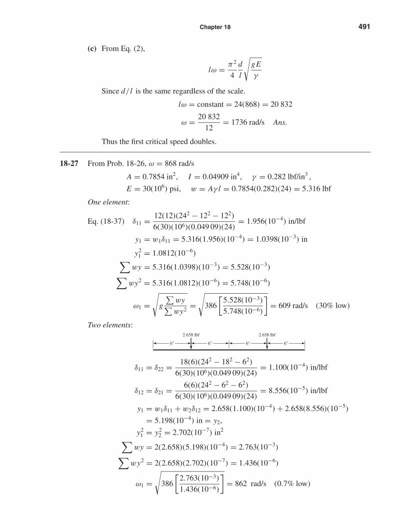
Two elements:
δ11 = δ22 = 18(6)(242 − 182 − 62)
6(30)(106)(0.049 09)(24)= 1.100(10−4) in/lbf
δ12 = δ21 = 6(6)(242 − 62 − 62)
6(30)(106)(0.049 09)(24)= 8.556(10−5) in/lbf
y1 = w1δ11 + w2δ12 = 2.658(1.100)(10−4) + 2.658(8.556)(10−5)
= 5.198(10−4) in = y2,
y21 = y2
2 = 2.702(10−7) in2∑wy = 2(2.658)(5.198)(10−4) = 2.763(10−3)∑
wy2 = 2(2.658)(2.702)(10−7) = 1.436(10−6)
ω1 =√
386
[2.763(10−3)
1.436(10−6)
]= 862 rad/s (0.7% low)
2.658 lbf2.658 lbf
6" 6" 6" 6"
shi20396_ch18.qxd 8/28/03 4:17 PM Page 491
492 Solutions Manual • Instructor’s Solution Manual to Accompany Mechanical Engineering Design
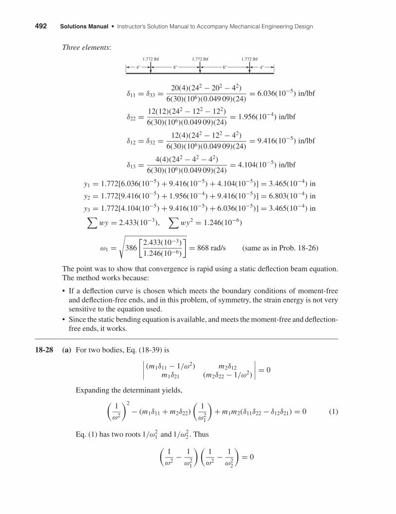
Three elements:
δ11 = δ33 = 20(4)(242 − 202 − 42)
6(30)(106)(0.049 09)(24)= 6.036(10−5) in/lbf
δ22 = 12(12)(242 − 122 − 122)
6(30)(106)(0.049 09)(24)= 1.956(10−4) in/lbf
δ12 = δ32 = 12(4)(242 − 122 − 42)
6(30)(106)(0.049 09)(24)= 9.416(10−5) in/lbf
δ13 = 4(4)(242 − 42 − 42)
6(30)(106)(0.049 09)(24)= 4.104(10−5) in/lbf
y1 = 1.772[6.036(10−5) + 9.416(10−5) + 4.104(10−5)] = 3.465(10−4) in
y2 = 1.772[9.416(10−5) + 1.956(10−4) + 9.416(10−5)] = 6.803(10−4) in
y3 = 1.772[4.104(10−5) + 9.416(10−5) + 6.036(10−5)] = 3.465(10−4) in∑wy = 2.433(10−3),
∑wy2 = 1.246(10−6)
ω1 =√
386
[2.433(10−3)
1.246(10−6)
]= 868 rad/s (same as in Prob. 18-26)
The point was to show that convergence is rapid using a static deflection beam equation.The method works because:
• If a deflection curve is chosen which meets the boundary conditions of moment-freeand deflection-free ends, and in this problem, of symmetry, the strain energy is not verysensitive to the equation used.
• Since the static bending equation is available, and meets the moment-free and deflection-free ends, it works.
18-28 (a) For two bodies, Eq. (18-39) is∣∣∣∣ (m1δ11 − 1/ω2) m2δ12m1δ21 (m2δ22 − 1/ω2)
∣∣∣∣ = 0
Expanding the determinant yields,(1
ω2
)2
− (m1δ11 + m2δ22)
(1
ω21
)+ m1m2(δ11δ22 − δ12δ21) = 0 (1)
Eq. (1) has two roots 1/ω21 and 1/ω2
2 . Thus
(1
ω2− 1
ω21
)(1
ω2− 1
ω22
)= 0
1.772 lbf1.772 lbf1.772 lbf
4"4" 8" 8"
shi20396_ch18.qxd 8/28/03 4:17 PM Page 492
Chapter 18 493
or, (1
ω2
)2
+(
1
ω21
+ 1
ω22
)(1
ω
)2
+(
1
ω21
)(1
ω22
)= 0 (2)
Equate the third terms of Eqs. (1) and (2), which must be identical.
1
ω21
1
ω22
= m1m2(δ11δ22 − δ12δ21) ⇒ 1
ω22
= ω21m1m2(δ11δ22 − δ12δ21)
and it follows that
ω2 = 1
ω1
√g2
w1w2(δ11δ22 − δ12δ21)Ans.
(b) In Ex. 18-5, Part (b) the first critical speed of the two-disk shaft (w1 = 35 lbf,w2 = 55 lbf) is ω1 = 124.7 rad/s. From part (a), using influence coefficients
ω2 = 1
124.7
√3862
35(55)[2.061(3.534) − 2.2342](10−8)= 466 rad/s Ans.
18-29 In Eq. (18-35) the term √
I/A appears. For a hollow unform diameter shaft,
√I
A=
√π
(d4
o − d4i
)/64
π(
d2o − d2
i
)/4
=√
1
16
(d2
o + d2i
)(d2
o − d2i
)d2
o − d2i
= 1
4
√d2
o + d2i
This means that when a solid shaft is hollowed out, the critical speed increases beyondthat of the solid shaft. By how much?
14
√d2
o + d2i
14
√d2
o
=√
1 +(
di
do
)2
The possible values of di are 0 ≤ di ≤ do , so the range of critical speeds is
ωs√
1 + 0 to about ωs√
1 + 1
or from ωs to √
2ωs . Ans.
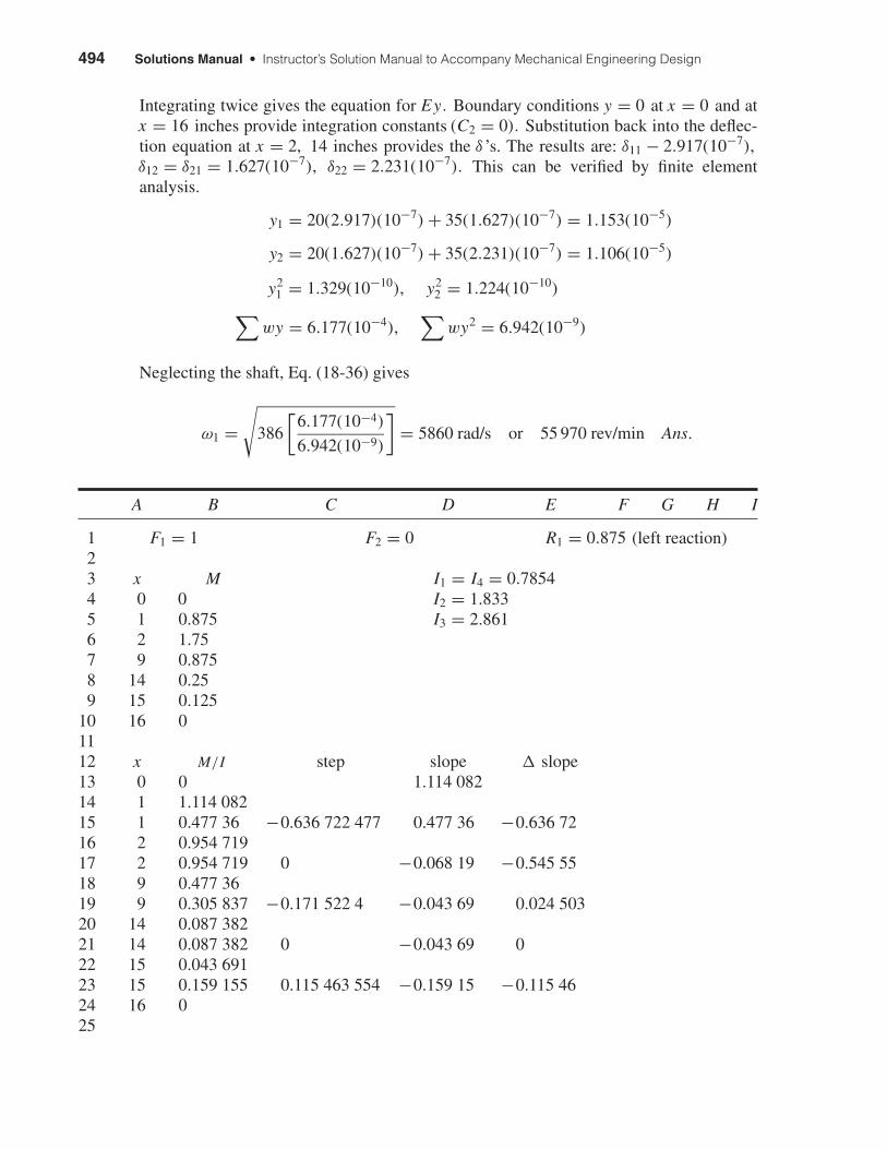
18-30 All steps will be modeled using singularity functions with a spreadsheet (see next page).Programming both loads will enable the user to first set the left load to 1, the right load to0 and calculate δ11 and δ21. Then setting left load to 0 and the right to 1 to get δ12 andδ22. The spreadsheet shown on the next page shows the δ11 and δ21 calculation. Table forM/I vs x is easy to make. The equation for M/I is:
M/I = D13x + C15〈x − 1〉0 + E15〈x − 1〉1 + E17〈x − 2〉1
+ C19〈x − 9〉0 + E19〈x − 9〉1 + E21〈x − 14〉1
+ C23〈x − 15〉0 + E23〈x − 15〉1
shi20396_ch18.qxd 8/28/03 4:17 PM Page 493
494 Solutions Manual • Instructor’s Solution Manual to Accompany Mechanical Engineering Design
Integrating twice gives the equation for Ey. Boundary conditions y = 0 at x = 0 and atx = 16 inches provide integration constants (C2 = 0). Substitution back into the deflec-tion equation at x = 2, 14 inches provides the δ ’s. The results are: δ11 − 2.917(10−7),δ12 = δ21 = 1.627(10−7), δ22 = 2.231(10−7). This can be verified by finite elementanalysis.
y1 = 20(2.917)(10−7) + 35(1.627)(10−7) = 1.153(10−5)
y2 = 20(1.627)(10−7) + 35(2.231)(10−7) = 1.106(10−5)
y21 = 1.329(10−10), y2
2 = 1.224(10−10)∑wy = 6.177(10−4),
∑wy2 = 6.942(10−9)
Neglecting the shaft, Eq. (18-36) gives
ω1 =√
386
[6.177(10−4)
6.942(10−9)
]= 5860 rad/s or 55 970 rev/min Ans.
A B C D E F G H I
1 F1 = 1 F2 = 0 R1 = 0.875 (left reaction)23 x M I1 = I4 = 0.78544 0 0 I2 = 1.8335 1 0.875 I3 = 2.8616 2 1.757 9 0.8758 14 0.259 15 0.125
10 16 01112 x M/I step slope � slope13 0 0 1.114 08214 1 1.114 08215 1 0.477 36 −0.636 722 477 0.477 36 −0.636 7216 2 0.954 71917 2 0.954 719 0 −0.068 19 −0.545 5518 9 0.477 3619 9 0.305 837 −0.171 522 4 −0.043 69 0.024 50320 14 0.087 38221 14 0.087 382 0 −0.043 69 022 15 0.043 69123 15 0.159 155 0.115 463 554 −0.159 15 −0.115 4624 16 025
shi20396_ch18.qxd 8/28/03 4:17 PM Page 494
Chapter 18 495
A B C D E F G H I
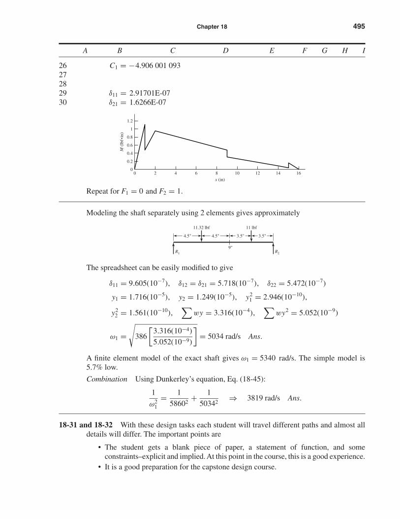
26 C1 = −4.906 001 093272829 δ11 = 2.91701E-0730 δ21 = 1.6266E-07
Repeat for F1 = 0 and F2 = 1.
Modeling the shaft separately using 2 elements gives approximately
The spreadsheet can be easily modified to give
δ11 = 9.605(10−7), δ12 = δ21 = 5.718(10−7), δ22 = 5.472(10−7)
y1 = 1.716(10−5), y2 = 1.249(10−5), y21 = 2.946(10−10),
y22 = 1.561(10−10),
∑wy = 3.316(10−4),
∑wy2 = 5.052(10−9)
ω1 =√
386
[3.316(10−4)
5.052(10−9)
]= 5034 rad/s Ans.
A finite element model of the exact shaft gives ω1 = 5340 rad/s. The simple model is5.7% low.
Combination Using Dunkerley’s equation, Eq. (18-45):
1
ω21
= 1
58602+ 1
50342⇒ 3819 rad/s Ans.
18-31 and 18-32 With these design tasks each student will travel different paths and almost alldetails will differ. The important points are
• The student gets a blank piece of paper, a statement of function, and someconstraints–explicit and implied. At this point in the course, this is a good experience.
• It is a good preparation for the capstone design course.
R1 R2
11 lbf11.32 lbf
4.5" 3.5"
9"
3.5"4.5"
0.8
1
1.2
0
0.2
0.4
0.6
0 1614121086
x (in)
M (
lbf•
in)
42
shi20396_ch18.qxd 8/28/03 4:17 PM Page 495
• The adequacy of their design must be demonstrated and possibly include a designer’snotebook.
• Many of the fundaments of the course, based on this text and this course, are useful. Thestudent will find them useful and notice that he/she is doing it.
• Don’t let the students create a time sink for themselves. Tell them how far you wantthem to go.
18-33 I used this task as a final exam when all of the students in the course had consistenttest scores going into the final examination; it was my expectation that they would notchange things much by taking the examination.
This problem is a learning experience. Following the task statement, the followingguidance was added.
• Take the first half hour, resisting the temptation of putting pencil to paper, and decidewhat the problem really is.
• Take another twenty minutes to list several possible remedies.
• Pick one, and show your instructor how you would implement it.
The students’ initial reaction is that he/she does not know much from the problemstatement. Then, slowly the realization sets in that they do know some important thingsthat the designer did not. They knew how it failed, where it failed, and that the designwasn’t good enough; it was close, though.
Also, a fix at the bearing seat lead-in could transfer the problem to the shoulder fillet,and the problem may not be solved.
To many students’s credit, they chose to keep the shaft geometry, and selected a newmaterial to realize about twice the Brinell hardness.
496 Solutions Manual • Instructor’s Solution Manual to Accompany Mechanical Engineering Design
shi20396_ch18.qxd 8/28/03 4:17 PM Page 496