Embed Size (px)
Citation preview
CCNA Security 1.2Instructor Packet Tracer Manual
This document is exclusive property of Cisco Systems, Inc. Permission is granted to print and copy this document for non-commercial distribution and exclusive use by instructors in the CCNA Security course as part of an official Cisco Networking Academy Program.
© 2014 Cisco and/or its affiliates. All rights reserved. This document is Cisco Public. Page 1 of 6
Packet Tracer - Configure Cisco Routers for Syslog, NTP, and
SSH Operations (Instructor Version) Instructor Note: Red font color or Gray highlights indicate text that appears in the instructor copy only.
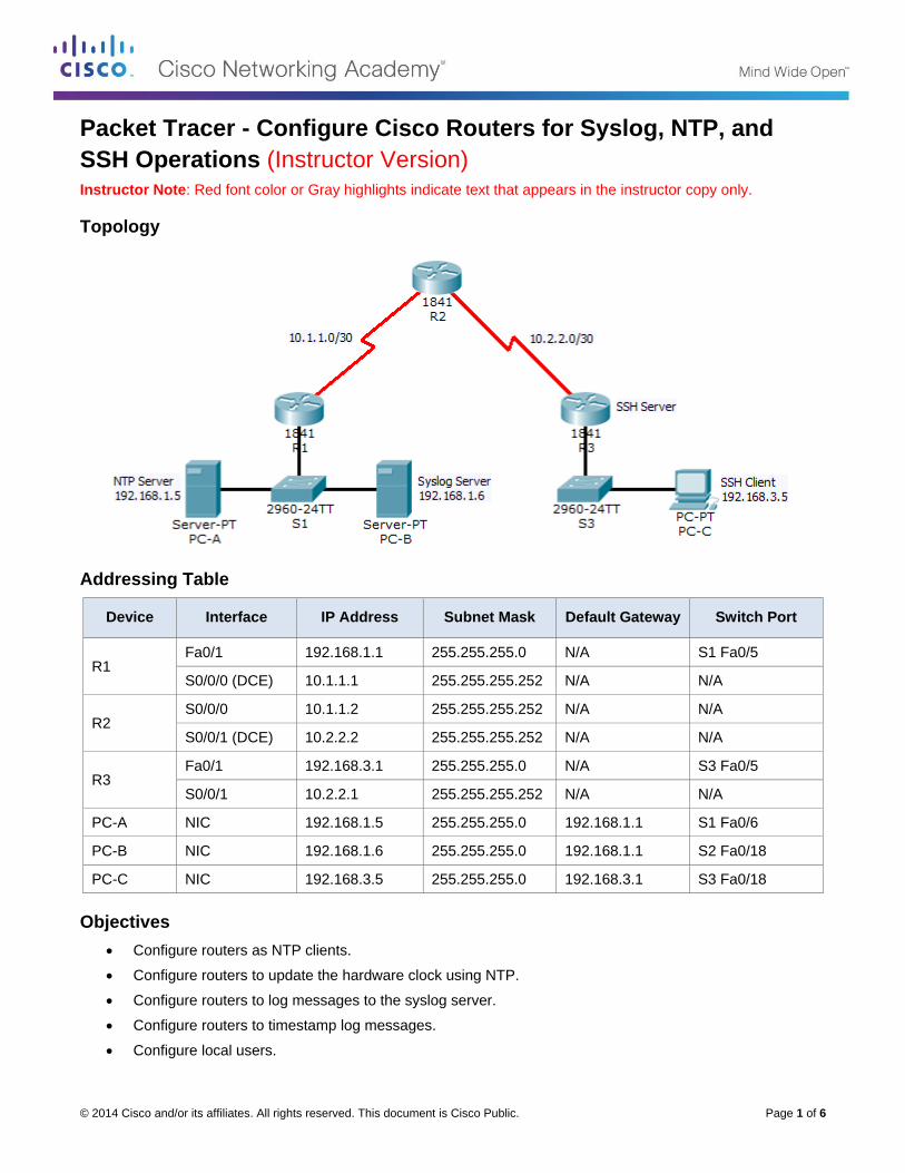
Topology
Addressing Table
Device Interface IP Address Subnet Mask Default Gateway Switch Port
R1 Fa0/1 192.168.1.1 255.255.255.0 N/A S1 Fa0/5
S0/0/0 (DCE) 10.1.1.1 255.255.255.252 N/A N/A
R2 S0/0/0 10.1.1.2 255.255.255.252 N/A N/A
S0/0/1 (DCE) 10.2.2.2 255.255.255.252 N/A N/A
R3 Fa0/1 192.168.3.1 255.255.255.0 N/A S3 Fa0/5
S0/0/1 10.2.2.1 255.255.255.252 N/A N/A
PC-A NIC 192.168.1.5 255.255.255.0 192.168.1.1 S1 Fa0/6
PC-B NIC 192.168.1.6 255.255.255.0 192.168.1.1 S2 Fa0/18
PC-C NIC 192.168.3.5 255.255.255.0 192.168.3.1 S3 Fa0/18
Objectives
Configure routers as NTP clients.
Configure routers to update the hardware clock using NTP.
Configure routers to log messages to the syslog server.
Configure routers to timestamp log messages.
Configure local users.
Packet Tracer - Configure Cisco Routers for Syslog, NTP, and SSH Operations
© 2014 Cisco and/or its affiliates. All rights reserved. This document is Cisco Public. Page 2 of 6
Configure VTY lines to accept SSH connections only.
Configure RSA key pair on SSH server.
Verify SSH connectivity from PC client and router client.
Background / Scenario
The network topology shows three routers. You will configure NTP and Syslog on all routers. You will configure SSH on R3.
Network Time Protocol (NTP) allows routers on the network to synchronize their time settings with an NTP server. A group of NTP clients that obtain time and date information from a single source have more consistent time settings and Syslog messages generated can be analyzed more easily. This can help when troubleshooting issues with network problems and attacks. When NTP is implemented in the network, it can be set up to synchronize to a private master clock, or to a publicly available NTP server on the Internet.
The NTP Server is the master NTP server in this lab. You will configure the routers to allow the software clock to be synchronized by NTP to the time server. Also, you will configure the routers to periodically update the hardware clock with the time learned from NTP. Otherwise, the hardware clock will tend to gradually lose or gain time (drift) and the software clock and hardware clock may become out of synchronization with each other.
The Syslog Server will provide message logging in this lab. You will configure the routers to identify the remote host (Syslog server) that will receive logging messages.
You will need to configure timestamp service for logging on the routers. Displaying the correct time and date in Syslog messages is vital when using Syslog to monitor a network. If the correct time and date of a message is not known, it can be difficult to determine what network event caused the message.
R2 is an ISP connected to two remote networks: R1 and R3. The local administrator at R3 can perform most router configurations and troubleshooting; however, because R3 is a managed router, the ISP needs access to R3 for occasional troubleshooting or updates. To provide this access in a secure manner, the administrators have agreed to use Secure Shell (SSH).
You use the CLI to configure the router to be managed securely using SSH instead of Telnet. SSH is a network protocol that establishes a secure terminal emulation connection to a router or other networking device. SSH encrypts all information that passes over the network link and provides authentication of the remote computer. SSH is rapidly replacing Telnet as the remote login tool of choice for network professionals.
The servers have been pre-configured for NTP and Syslog services respectively. NTP will not require authentication. The routers have been pre-configured with the following:
Enable password: ciscoenpa55
Password for vty lines: ciscovtypa55
Static routing
Part 1: Configure Routers as NTP Clients
Step 1: Test Connectivity.
Ping from PC-C to R3.
Ping from R2 to R3.
Telnet from PC-C to R3. Exit the Telnet session.
Telnet from R2 to R3. Exit the Telnet session.
Packet Tracer - Configure Cisco Routers for Syslog, NTP, and SSH Operations
© 2014 Cisco and/or its affiliates. All rights reserved. This document is Cisco Public. Page 3 of 6
Step 2: Configure R1, R2, and R3 as NTP clients.
R1(config)# ntp server 192.168.1.5
R2(config)# ntp server 192.168.1.5
R3(config)# ntp server 192.168.1.5
Verify client configuration using the command show ntp status.
Step 3: Configure routers to update hardware clock.
Configure R1, R2, and R3 to periodically update the hardware clock with the time learned from NTP.
R1(config)# ntp update-calendar
R2(config)# ntp update-calendar
R3(config)# ntp update-calendar
Verify that the hardware clock was updated using the command show clock.
Step 4: Configure routers to timestamp log messages.
Configure timestamp service for logging on the routers.
R1(config)# service timestamps log datetime msec
R2(config)# service timestamps log datetime msec
R3(config)# service timestamps log datetime msec
Part 2: Configure Routers to Log Messages to the Syslog Server
Step 1: Configure the routers to identify the remote host (Syslog Server) that will receive logging messages.
R1(config)# logging host 192.168.1.6
R2(config)# logging host 192.168.1.6
R3(config)# logging host 192.168.1.6
The router console will display a message that logging has started.
Step 2: Verify logging configuration using the command show logging.
Step 3: Examine logs of the Syslog Server.
From the Services tab of the Syslog Server’s dialogue box, select the Syslog services button. Observe the logging messages received from the routers.
Note: Log messages can be generated on the server by executing commands on the router. For example, entering and exiting global configuration mode will generate an informational configuration message.
Part 3: Configure R3 to Support SSH Connections
Step 1: Configure a domain name.
Configure a domain name of ccnasecurity.com on R3.
R3(config)# ip domain-name ccnasecurity.com
Packet Tracer - Configure Cisco Routers for Syslog, NTP, and SSH Operations
© 2014 Cisco and/or its affiliates. All rights reserved. This document is Cisco Public. Page 4 of 6
Step 2: Configure users for login to the SSH server on R3.
Create a user ID of SSHadmin with the highest possible privilege level and a secret password of ciscosshpa55.
R3(config)# username SSHadmin privilege 15 secret ciscosshpa55
Step 3: Configure the incoming VTY lines on R3.
Use the local user accounts for mandatory login and validation. Accept only SSH connections.
R3 (config)# line vty 0 4
R3 (config-line)# login local
R3(config-line)# transport input ssh
Step 4: Erase existing key pairs on R3.
Any existing RSA key pairs should be erased on the router.
R3(config)# crypto key zeroize rsa
Note: If no keys exist, you might receive this message: % No Signature RSA Keys found in
configuration.
Step 5: Generate the RSA encryption key pair for R3.
The router uses the RSA key pair for authentication and encryption of transmitted SSH data. Configure the RSA keys with a modulus of 1024. The default is 512, and the range is from 360 to 2048.
R3(config)# crypto key generate rsa
The name for the keys will be: R3.ccnasecurity.com
Choose the size of the key modulus in the range of 360 to 2048 for your
General Purpose Keys. Choosing a key modulus greater than 512 may take
a few minutes.
How many bits in the modulus [512]: 1024
% Generating 1024 bit RSA keys, keys will be non-exportable...[OK]
Note: The command to generate RSA encryption key pairs for R3 in Packet Tracer differs from those used in the lab.
Step 6: Verify the SSH configuration.
Use the show ip ssh command to see the current settings. Verify that the authentication timeout and retries are at their default values of 120 and 3.
Step 7: Configure SSH timeouts and authentication parameters.
The default SSH timeouts and authentication parameters can be altered to be more restrictive. Set the timeout to 90 seconds, the number of authentication retries to 2, and the version to 2.
R3(config)# ip ssh time-out 90
R3(config)# ip ssh authentication-retries 2
R3(config)# ip ssh version 2
Issue the show ip ssh command again to confirm that the values have been changed.
Packet Tracer - Configure Cisco Routers for Syslog, NTP, and SSH Operations
© 2014 Cisco and/or its affiliates. All rights reserved. This document is Cisco Public. Page 5 of 6
Step 8: Attempt to connect to R3 via Telnet from PC-C.
Open the Desktop of PC-C. Select the Command Prompt icon. From PC-C, enter the command to connect to R3 via Telnet.
PC> telnet 192.168.3.1
This connection should fail because R3 has been configured to accept only SSH connections on the virtual terminal lines.
Step 9: Connect to R3 using SSH on PC-C.
Open the Desktop of PC-C. Select the Command Prompt icon. From PC-C, enter the command to connect to R3 via SSH. When prompted for the password, enter the password configured for the administrator ciscosshpa55.
PC> ssh –l SSHadmin 192.168.3.1
Step 10: Connect to R3 using SSH on R2.
In order to troubleshoot and maintain R3, the administrator at the ISP must use SSH to access the router CLI. From the CLI of R2, enter the command to connect to R3 via SSH version 2 using the SSHadmin user account. When prompted for the password, enter the password configured for the administrator: ciscosshpa55.
R2# ssh –v 2 –l SSHadmin 10.2.2.1
Step 11: Check results.
Your completion percentage should be 100%. Click Check Results to view the feedback and verification of which required components have been completed.
!!!Scripts for R1 and R2!!!!
conf t
service timestamps log datetime msec
logging 192.168.1.6
ntp server 192.168.1.5
ntp update-calendar
end
!!!Scripts for R3!!!!
conf t
service timestamps log datetime msec
logging 192.168.1.6
ntp server 192.168.1.5
ntp update-calendar
ip domain-name ccnasecurity.com
username SSHadmin privilege 15 secret ciscosshpa55
line vty 0 4
login local
transport input ssh
crypto key zeroize rsa
crypto key generate rsa
1024
ip ssh time-out 90

Packet Tracer - Configure Cisco Routers for Syslog, NTP, and SSH Operations
© 2014 Cisco and/or its affiliates. All rights reserved. This document is Cisco Public. Page 6 of 6
ip ssh authentication-retries 2
ip ssh version 2
end
© 2014 Cisco and/or its affiliates. All rights reserved. This document is Cisco Public. Page 1 of 6
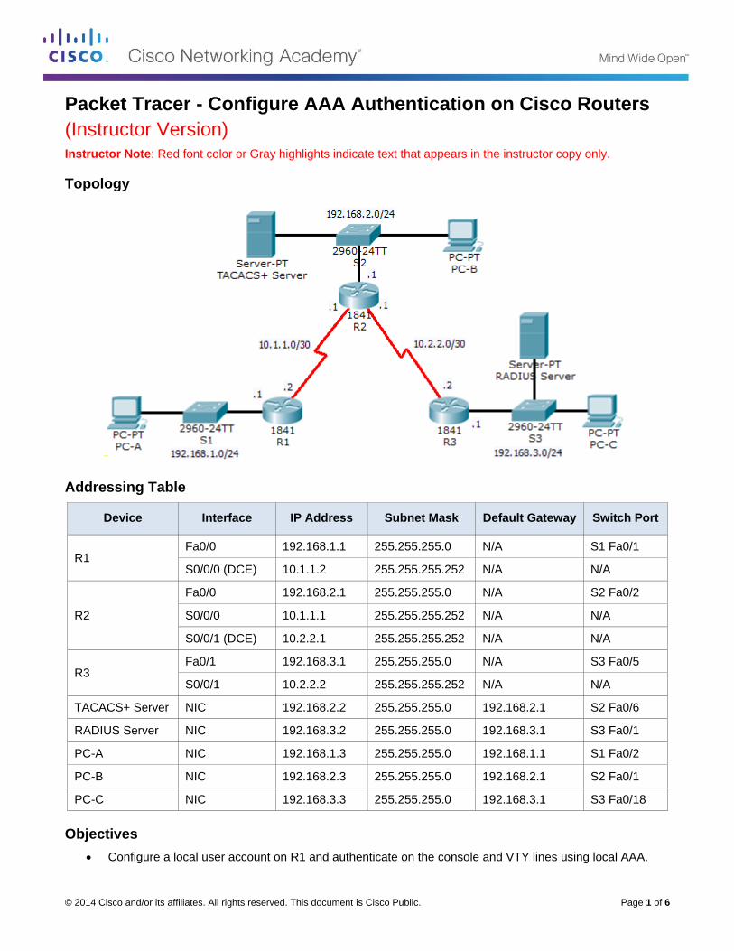
Packet Tracer - Configure AAA Authentication on Cisco Routers
(Instructor Version) Instructor Note: Red font color or Gray highlights indicate text that appears in the instructor copy only.
Topology
Addressing Table
Device Interface IP Address Subnet Mask Default Gateway Switch Port
R1 Fa0/0 192.168.1.1 255.255.255.0 N/A S1 Fa0/1
S0/0/0 (DCE) 10.1.1.2 255.255.255.252 N/A N/A
R2
Fa0/0 192.168.2.1 255.255.255.0 N/A S2 Fa0/2
S0/0/0 10.1.1.1 255.255.255.252 N/A N/A
S0/0/1 (DCE) 10.2.2.1 255.255.255.252 N/A N/A
R3 Fa0/1 192.168.3.1 255.255.255.0 N/A S3 Fa0/5
S0/0/1 10.2.2.2 255.255.255.252 N/A N/A
TACACS+ Server NIC 192.168.2.2 255.255.255.0 192.168.2.1 S2 Fa0/6
RADIUS Server NIC 192.168.3.2 255.255.255.0 192.168.3.1 S3 Fa0/1
PC-A NIC 192.168.1.3 255.255.255.0 192.168.1.1 S1 Fa0/2
PC-B NIC 192.168.2.3 255.255.255.0 192.168.2.1 S2 Fa0/1
PC-C NIC 192.168.3.3 255.255.255.0 192.168.3.1 S3 Fa0/18
Objectives
Configure a local user account on R1 and authenticate on the console and VTY lines using local AAA.
Packet Tracer - Configure AAA Authentication on Cisco Routers
© 2014 Cisco and/or its affiliates. All rights reserved. This document is Cisco Public. Page 2 of 6
Verify local AAA authentication from the R1 console and the PC-A client.
Configure a server-based AAA authentication using TACACS+.
Verify server-based AAA authentication from PC-B client.
Configure a server-based AAA authentication using RADIUS.
Verify server-based AAA authentication from PC-C client.
Background / Scenario
The network topology shows routers R1, R2 and R3. Currently all administrative security is based on knowledge of the enable secret password. Your task is to configure and test local and server-based AAA solutions.
You will create a local user account and configure local AAA on router R1 to test the console and VTY logins.
o User account: Admin1 and password admin1pa55
You will then configure router R2 to support server-based authentication using the TACACS+ protocol. The TACACS+ server has been pre-configured with the following:
o Client: R2 using the keyword tacacspa55
o User account: Admin2 and password admin2pa55
Finally, you will configure router R3 to support server-based authentication using the RADIUS protocol. The RADIUS server has been pre-configured with the following:
o Client: R3 using the keyword radiuspa55
o User account: Admin3 and password admin3pa55
The routers have also been pre-configured with the following:
o Enable secret password: ciscoenpa55
o RIP version 2
Note: The console and VTY lines have not been pre-configured.
Part 1: Configure Local AAA Authentication for Console Access on R1
Step 1: Test connectivity.
Ping from PC-A to PC-B.
Ping from PC-A to PC-C.
Ping from PC-B to PC-C.
Step 2: Configure a local username on R1.
Configure a username of Admin1 and secret password of admin1pa55.
R1(config)# username Admin1 secret admin1pa55
Step 3: Configure local AAA authentication for console access on R1.
Enable AAA on R1 and configure AAA authentication for console login to use the local database.
R1(config)# aaa new-model
R1(config)# aaa authentication login default local
Packet Tracer - Configure AAA Authentication on Cisco Routers
© 2014 Cisco and/or its affiliates. All rights reserved. This document is Cisco Public. Page 3 of 6
Step 4: Configure the line console to use the defined AAA authentication method.
Enable AAA on R1 and configure AAA authentication for console login to use the default method list.
R1(config)# line console 0
R1(config-line)# login authentication default
Step 5: Verify the AAA authentication method.
Verify the user EXEC login using the local database.
R1(config-line)# end
%SYS-5-CONFIG_I: Configured from console by console
R1# exit
R1 con0 is now available
Press RETURN to get started.
************ AUTHORIZED ACCESS ONLY *************
UNAUTHORIZED ACCESS TO THIS DEVICE IS PROHIBITED.
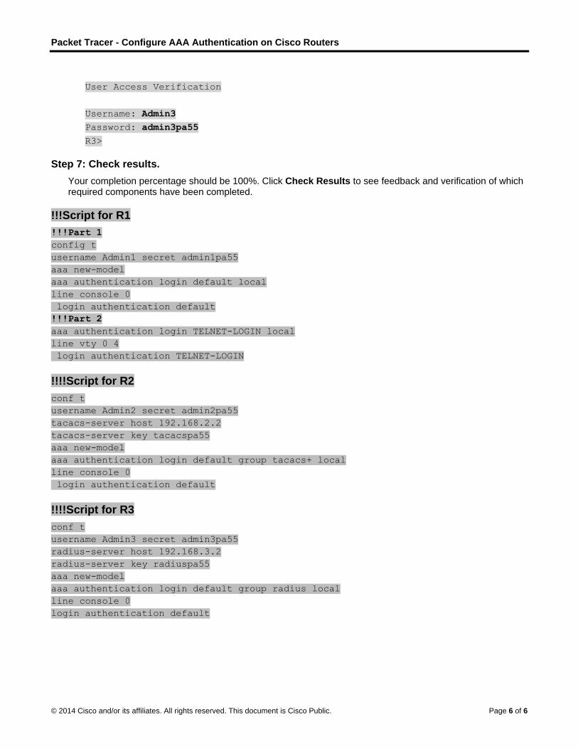
User Access Verification
Username: Admin1
Password: admin1pa55
R1>
Part 2: Configure Local AAA Authentication for VTY Lines on R1
Step 1: Configure a named list AAA authentication method for VTY lines on R1.
Configure a named list called TELNET-LOGIN to authenticate logins using local AAA.
R1(config)# aaa authentication login TELNET-LOGIN local
Step 2: Configure the VTY lines to use the defined AAA authentication method.
Configure the VTY lines to use the named AAA method.
R1(config)# line vty 0 4
R1(config-line)# login authentication TELNET-LOGIN
R1(config-line)# end
Step 3: Verify the AAA authentication method.
Verify the Telnet configuration. From the command prompt of PC-A, Telnet to R1.
PC> telnet 192.168.1.1
************ AUTHORIZED ACCESS ONLY *************
UNAUTHORIZED ACCESS TO THIS DEVICE IS PROHIBITED.
Packet Tracer - Configure AAA Authentication on Cisco Routers
© 2014 Cisco and/or its affiliates. All rights reserved. This document is Cisco Public. Page 4 of 6
User Access Verification
Username: Admin1
Password: admin1pa55
R1>
Part 3: Configure Server-Based AAA Authentication Using TACACS+ on R2
Step 1: Configure a backup local database entry called Admin.
For backup purposes, configure a local username of Admin2 and secret password of admin2pa55.
R2(config)# username Admin2 secret admin2pa55
Step 2: Verify the TACACS+ Server configuration.
Select the TACACS+ Server and from the Services tab, click on AAA. Notice that there is a Network configuration entry for R2 and a User Setup entry for Admin2.
Step 3: Configure the TACACS+ server specifics on R2.
Configure the AAA TACACS server IP address and secret key on R2.
R2(config)# tacacs-server host 192.168.2.2
R2(config)# tacacs-server key tacacspa55
Step 4: Configure AAA login authentication for console access on R2.
Enable AAA on R2 and configure all logins to authenticate using the AAA TACACS+ server and if not available, then use the local database.
R2(config)# aaa new-model
R2(config)# aaa authentication login default group tacacs+ local
Step 5: Configure the line console to use the defined AAA authentication method.
Configure AAA authentication for console login to use the default AAA authentication method.
R2(config)# line console 0
R2(config-line)# login authentication default
Step 6: Verify the AAA authentication method.
Verify the user EXEC login using the AAA TACACS+ server.
R2(config-line)# end
%SYS-5-CONFIG_I: Configured from console by console
R2# exit
R2 con0 is now available
Press RETURN to get started.
************ AUTHORIZED ACCESS ONLY *************
UNAUTHORIZED ACCESS TO THIS DEVICE IS PROHIBITED.
Packet Tracer - Configure AAA Authentication on Cisco Routers
© 2014 Cisco and/or its affiliates. All rights reserved. This document is Cisco Public. Page 5 of 6
User Access Verification
Username: Admin2
Password: admin2pa55
R2>
Part 4: Configure Server-Based AAA Authentication Using RADIUS on R3
Step 1: Configure a backup local database entry called Admin.
For backup purposes, configure a local username of Admin3 and secret password of admin3pa55.
R3(config)# username Admin3 secret admin3pa55
Step 2: Verify the RADIUS Server configuration.
Select the RADIUS Server and from the Services tab, click on AAA. Notice that there is a Network configuration entry for R3 and a User Setup entry for Admin3.
Step 3: Configure the RADIUS server specifics on R3.
Configure the AAA RADIUS server IP address and secret key on R3.
R3(config)# radius-server host 192.168.3.2
R3(config)# radius-server key radiuspa55
Step 4: Configure AAA login authentication for console access on R3.
Enable AAA on R3 and configure all logins to authenticate using the AAA RADIUS server and if not available, then use the local database.
R3(config)# aaa new-model
R3(config)# aaa authentication login default group radius local
Step 5: Configure the line console to use the defined AAA authentication method.
Configure AAA authentication for console login to use the default AAA authentication method.
R3(config)# line console 0
R3(config-line)# login authentication default
Step 6: Verify the AAA authentication method.
Verify the user EXEC login using the AAA RADIUS server.
R3(config-line)# end
%SYS-5-CONFIG_I: Configured from console by console
R3# exit
R3 con0 is now available
Press RETURN to get started.
************ AUTHORIZED ACCESS ONLY *************
UNAUTHORIZED ACCESS TO THIS DEVICE IS PROHIBITED.
Packet Tracer - Configure AAA Authentication on Cisco Routers
© 2014 Cisco and/or its affiliates. All rights reserved. This document is Cisco Public. Page 6 of 6
User Access Verification
Username: Admin3
Password: admin3pa55
R3>
Step 7: Check results.
Your completion percentage should be 100%. Click Check Results to see feedback and verification of which required components have been completed.
!!!Script for R1
!!!Part 1
config t
username Admin1 secret admin1pa55
aaa new-model
aaa authentication login default local
line console 0
login authentication default
!!!Part 2
aaa authentication login TELNET-LOGIN local
line vty 0 4
login authentication TELNET-LOGIN
!!!!Script for R2
conf t
username Admin2 secret admin2pa55
tacacs-server host 192.168.2.2
tacacs-server key tacacspa55
aaa new-model
aaa authentication login default group tacacs+ local
line console 0
login authentication default
!!!!Script for R3
conf t
username Admin3 secret admin3pa55
radius-server host 192.168.3.2
radius-server key radiuspa55
aaa new-model
aaa authentication login default group radius local
line console 0
login authentication default
© 2014 Cisco and/or its affiliates. All rights reserved. This document is Cisco Public. Page 1 of 5
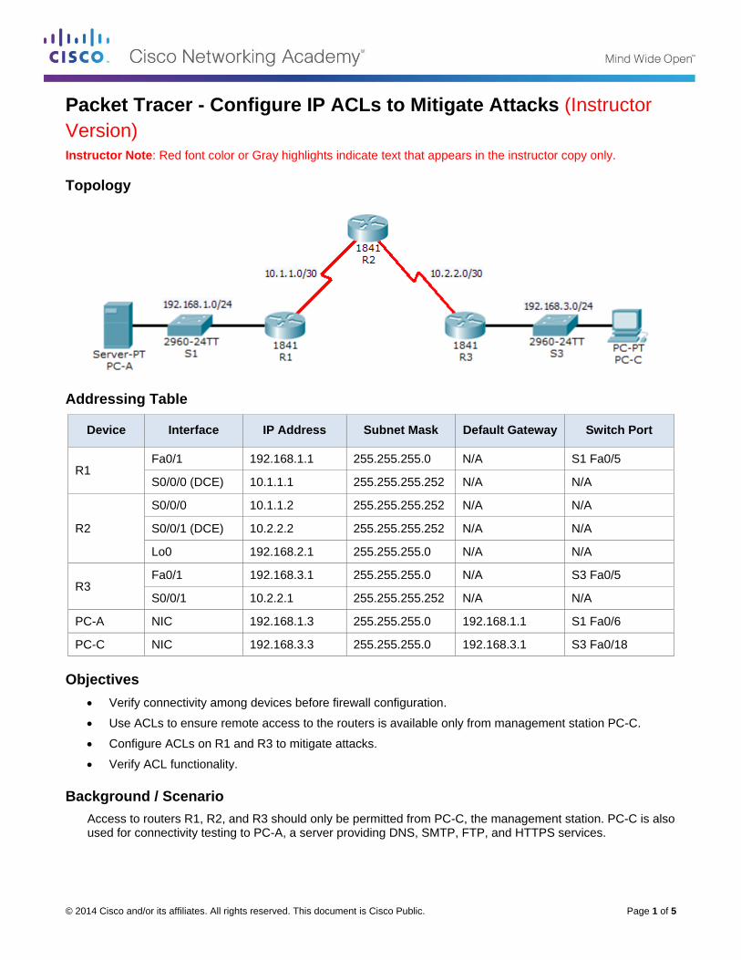
Packet Tracer - Configure IP ACLs to Mitigate Attacks (Instructor
Version) Instructor Note: Red font color or Gray highlights indicate text that appears in the instructor copy only.
Topology
Addressing Table
Device Interface IP Address Subnet Mask Default Gateway Switch Port
R1 Fa0/1 192.168.1.1 255.255.255.0 N/A S1 Fa0/5
S0/0/0 (DCE) 10.1.1.1 255.255.255.252 N/A N/A
R2
S0/0/0 10.1.1.2 255.255.255.252 N/A N/A
S0/0/1 (DCE) 10.2.2.2 255.255.255.252 N/A N/A
Lo0 192.168.2.1 255.255.255.0 N/A N/A
R3 Fa0/1 192.168.3.1 255.255.255.0 N/A S3 Fa0/5
S0/0/1 10.2.2.1 255.255.255.252 N/A N/A
PC-A NIC 192.168.1.3 255.255.255.0 192.168.1.1 S1 Fa0/6
PC-C NIC 192.168.3.3 255.255.255.0 192.168.3.1 S3 Fa0/18
Objectives
Verify connectivity among devices before firewall configuration.
Use ACLs to ensure remote access to the routers is available only from management station PC-C.
Configure ACLs on R1 and R3 to mitigate attacks.
Verify ACL functionality.
Background / Scenario
Access to routers R1, R2, and R3 should only be permitted from PC-C, the management station. PC-C is also used for connectivity testing to PC-A, a server providing DNS, SMTP, FTP, and HTTPS services.
Packet Tracer - Configure IP ACLs to Mitigate Attacks
© 2014 Cisco and/or its affiliates. All rights reserved. This document is Cisco Public. Page 2 of 5
Standard operating procedure is to apply ACLs on edge routers to mitigate common threats based on source and/or destination IP address. In this activity, you create ACLs on edge routers R1 and R3 to achieve this goal. You then verify ACL functionality from internal and external hosts.
The routers have been pre-configured with the following:
o Enable password: ciscoenpa55
o Password for console: ciscoconpa55
o Username for VTY lines: SSHadmin
o Password for VTY lines: ciscosshpa55
o IP addressing
o Static routing
Part 1: Verify Basic Network Connectivity
Verify network connectivity prior to configuring the IP ACLs.
Step 1: From PC-A, verify connectivity to PC-C and R2.
a. From the command prompt, ping PC-C (192.168.3.3).
b. From the command prompt, establish a SSH session to R2 Lo0 interface (192.168.2.1) using username SSHadmin and password ciscosshpa55. When finished, exit the SSH session.
PC> ssh -l SSHadmin 192.168.2.1
Step 2: From PC-C, verify connectivity to PC-A and R2.
a. From the command prompt, ping PC-A (192.168.1.3).
b. From the command prompt, establish a SSH session to R2 Lo0 interface (192.168.2.1) using username SSHadmin and password ciscosshpa55. Close the SSH session when finished.
PC> ssh -l SSHadmin 192.168.2.1
c. Open a web browser to the PC-A server (192.168.1.3) to display the web page. Close the browser when done.
Part 2: Secure Access to Routers
Step 1: Configure ACL 10 to block all remote access to the routers except from PC-C.
Use the access-list command to create a numbered IP ACL on R1, R2, and R3.
R1(config)# access-list 10 permit 192.168.3.3 0.0.0.0
R2(config)# access-list 10 permit 192.168.3.3 0.0.0.0
R3(config)# access-list 10 permit 192.168.3.3 0.0.0.0
Step 2: Apply ACL 10 to ingress traffic on the VTY lines.
Use the access-class command to apply the access list to incoming traffic on the VTY lines.
R1(config-line)# access-class 10 in
R2(config-line)# access-class 10 in
R3(config-line)# access-class 10 in
Packet Tracer - Configure IP ACLs to Mitigate Attacks
© 2014 Cisco and/or its affiliates. All rights reserved. This document is Cisco Public. Page 3 of 5
Step 3: Verify exclusive access from management station PC-C.
a. Establish a SSH session to 192.168.2.1 from PC-C (should be successful).
PC> ssh –l SSHadmin 192.168.2.1
b. Establish a SSH session to 192.168.2.1 from PC-A (should fail).
Part 3: Create a Numbered IP ACL 120 on R1
Permit any outside host to access DNS, SMTP, and FTP services on server PC-A, deny any outside host access to HTTPS services on PC-A, and permit PC-C to access R1 via SSH.
Step 1: Verify that PC-C can access the PC-A via HTTPS using the web browser.
Be sure to disable HTTP and enable HTTPS on server PC-A.
Step 2: Configure ACL 120 to specifically permit and deny the specified traffic.
Use the access-list command to create a numbered IP ACL.
R1(config)# access-list 120 permit udp any host 192.168.1.3 eq domain
R1(config)# access-list 120 permit tcp any host 192.168.1.3 eq smtp
R1(config)# access-list 120 permit tcp any host 192.168.1.3 eq ftp
R1(config)# access-list 120 deny tcp any host 192.168.1.3 eq 443
R1(config)# access-list 120 permit tcp host 192.168.3.3 host 10.1.1.1 eq 22
Step 3: Apply the ACL to interface S0/0/0.
Use the ip access-group command to apply the access list to incoming traffic on interface S0/0/0.
R1(config)# interface s0/0/0
R1(config-if)# ip access-group 120 in
Step 4: Verify that PC-C cannot access PC-A via HTTPS using the web browser.
Part 4: Modify An Existing ACL on R1
Permit ICMP echo replies and destination unreachable messages from the outside network (relative to R1); deny all other incoming ICMP packets.
Step 1: Verify that PC-A cannot successfully ping the loopback interface on R2.
Step 2: Make any necessary changes to ACL 120 to permit and deny the specified traffic.
Use the access-list command to create a numbered IP ACL.
R1(config)# access-list 120 permit icmp any any echo-reply
R1(config)# access-list 120 permit icmp any any unreachable
R1(config)# access-list 120 deny icmp any any
R1(config)# access-list 120 permit ip any any
Step 3: Verify that PC-A can successfully ping the loopback interface on R2.
Part 5: Create a Numbered IP ACL 110 on R3
Deny all outbound packets with source address outside the range of internal IP addresses on R3.
Packet Tracer - Configure IP ACLs to Mitigate Attacks
© 2014 Cisco and/or its affiliates. All rights reserved. This document is Cisco Public. Page 4 of 5
Step 1: Configure ACL 110 to permit only traffic from the inside network.
Use the access-list command to create a numbered IP ACL.
R3(config)# access-list 110 permit ip 192.168.3.0 0.0.0.255 any
Step 2: Apply the ACL to interface F0/1.
Use the ip access-group command to apply the access list to incoming traffic on interface F0/1.
R3(config)# interface fa0/1
R3(config-if)# ip access-group 110 in
Part 6: Create a Numbered IP ACL 100 on R3
On R3, block all packets containing the source IP address from the following pool of addresses: 127.0.0.0/8, any RFC 1918 private addresses, and any IP multicast address.
Step 1: Configure ACL 100 to block all specified traffic from the outside network.
You should also block traffic sourced from your own internal address space if it is not an RFC 1918 address (in this activity, your internal address space is part of the private address space specified in RFC 1918).
Use the access-list command to create a numbered IP ACL.
R3(config)# access-list 100 deny ip 10.0.0.0 0.255.255.255 any
R3(config)# access-list 100 deny ip 172.16.0.0 0.15.255.255 any
R3(config)# access-list 100 deny ip 192.168.0.0 0.0.255.255 any
R3(config)# access-list 100 deny ip 127.0.0.0 0.255.255.255 any
R3(config)# access-list 100 deny ip 224.0.0.0 15.255.255.255 any
R3(config)# access-list 100 permit ip any any
Step 2: Apply the ACL to interface Serial 0/0/1.
Use the ip access-group command to apply the access list to incoming traffic on interface Serial 0/0/1.
R3(config)# interface s0/0/1
R3(config-if)# ip access-group 100 in
Step 3: Confirm that the specified traffic entering interface Serial 0/0/1 is dropped.
From the PC-C command prompt, ping the PC-A server. The ICMP echo replies are blocked by the ACL since they are sourced from the 192.168.0.0/16 address space.
Step 4: Check results.
Your completion percentage should be 100%. Click Check Results to see feedback and verification of which required components have been completed.
!!!Script for R1
access-list 10 permit 192.168.3.3 0.0.0.0
line vty 0 4
access-class 10 in
access-list 120 permit udp any host 192.168.1.3 eq domain
access-list 120 permit tcp any host 192.168.1.3 eq smtp
access-list 120 permit tcp any host 192.168.1.3 eq ftp
access-list 120 deny tcp any host 192.168.1.3 eq 443
Packet Tracer - Configure IP ACLs to Mitigate Attacks
© 2014 Cisco and/or its affiliates. All rights reserved. This document is Cisco Public. Page 5 of 5
access-list 120 permit tcp host 192.168.3.3 host 10.1.1.1 eq 22
interface s0/0/0
ip access-group 120 in
access-list 120 permit icmp any any echo-reply
access-list 120 permit icmp any any unreachable
access-list 120 deny icmp any any
access-list 120 permit ip any any
!!!Script for R2
access-list 10 permit 192.168.3.3 0.0.0.0
line vty 0 4
access-class 10 in
!!!Script for R3
access-list 10 permit 192.168.3.3 0.0.0.0
line vty 0 4
access-class 10 in
access-list 100 deny ip 10.0.0.0 0.255.255.255 any
access-list 100 deny ip 172.16.0.0 0.15.255.255 any
access-list 100 deny ip 192.168.0.0 0.0.255.255 any
access-list 100 deny ip 127.0.0.0 0.255.255.255 any
access-list 100 deny ip 224.0.0.0 15.255.255.255 any
access-list 100 permit ip any any
interface s0/0/1
ip access-group 100 in
access-list 110 permit ip 192.168.3.0 0.0.0.255 any
interface fa0/1
ip access-group 110 in
© 2014 Cisco and/or its affiliates. All rights reserved. This document is Cisco Public. Page 1 of 5
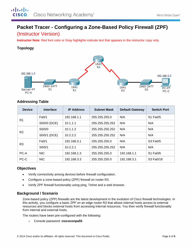
Packet Tracer - Configuring a Zone-Based Policy Firewall (ZPF)
(Instructor Version) Instructor Note: Red font color or Gray highlights indicate text that appears in the instructor copy only.
Topology
Addressing Table
Device Interface IP Address Subnet Mask Default Gateway Switch Port
R1 Fa0/1 192.168.1.1 255.255.255.0 N/A S1 Fa0/5
S0/0/0 (DCE) 10.1.1.1 255.255.255.252 N/A N/A
R2 S0/0/0 10.1.1.2 255.255.255.252 N/A N/A
S0/0/1 (DCE) 10.2.2.2 255.255.255.252 N/A N/A
R3 Fa0/1 192.168.3.1 255.255.255.0 N/A S3 Fa0/5
S0/0/1 10.2.2.1 255.255.255.252 N/A N/A
PC-A NIC 192.168.1.3 255.255.255.0 192.168.1.1 S1 Fa0/6
PC-C NIC 192.168.3.3 255.255.255.0 192.168.3.1 S3 Fa0/18
Objectives
Verify connectivity among devices before firewall configuration.
Configure a zone-based policy (ZPF) firewall on router R3.
Verify ZPF firewall functionality using ping, Telnet and a web browser.
Background / Scenario
Zone-based policy (ZPF) firewalls are the latest development in the evolution of Cisco firewall technologies. In this activity, you configure a basic ZPF on an edge router R3 that allows internal hosts access to external resources and blocks external hosts from accessing internal resources. You then verify firewall functionality from internal and external hosts.
The routers have been pre-configured with the following:
o Console password: ciscoconpa55
Packet Tracer - Configuring a Zone-Based Policy Firewall (ZPF)
© 2014 Cisco and/or its affiliates. All rights reserved. This document is Cisco Public. Page 2 of 5
o Password for vty lines: ciscovtypa55
o Enable password: ciscoenpa55
o Host names and IP addressing
o Static routing
Part 1: Verify Basic Network Connectivity
Verify network connectivity prior to configuring the zone-based policy firewall.
Step 1: From the PC-A command prompt, ping PC-C at 192.168.3.3.
Step 2: From the PC-C command prompt, telnet to the Router R2 S0/0/1 interface at 10.2.2.2. Exit the Telnet session.
Step 3: From PC-C, open a web browser to the PC-A server.
a. Click the Desktop tab and click the Web Browser application. Enter the PC-A IP address 192.168.1.3 as the URL. The Packet Tracer welcome page from the web server should be displayed.
b. Close the browser on PC-C.
Part 2: Create the Firewall Zones on Router R3
Note: For all configuration tasks, be sure to use the exact names as specified.
Step 1: Create an internal zone.
Use the zone security command to create a zone named IN-ZONE.
R3(config)# zone security IN-ZONE
Step 2: Create an external zone.
Use the zone security command to create a zone named OUT-ZONE.
R3(config-sec-zone)# zone security OUT-ZONE
R3(config-sec-zone)# exit
Part 3: Define a Traffic Class and Access List
Step 1: Create an ACL that defines internal traffic.
Use the access-list command to create extended ACL 101 to permit all IP protocols from the 192.168.3.0/24 source network to any destination.
R3(config)# access-list 101 permit ip 192.168.3.0 0.0.0.255 any
Step 2: Create a class map referencing the internal traffic ACL.
Use the class-map type inspect command with the match-all option to create a class map named IN-NET-CLASS-MAP. Use the match access-group command to match ACL 101.
R3(config)# class-map type inspect match-all IN-NET-CLASS-MAP
R3(config-cmap)# match access-group 101
R3(config-cmap)# exit
Packet Tracer - Configuring a Zone-Based Policy Firewall (ZPF)
© 2014 Cisco and/or its affiliates. All rights reserved. This document is Cisco Public. Page 3 of 5
Note: Although not supported in this Packet Tracer exercise, individual protocols (HTTP, FTP, etc.) can be specific to be matched using the match-any option in order to provide more precise control over what type of traffic is inspected.
Part 4: Specify Firewall Policies
Step 1: Create a policy map to determine what to do with matched traffic.
Use the policy-map type inspect command and create a policy map named IN-2-OUT-PMAP.
R3(config)# policy-map type inspect IN-2-OUT-PMAP
Step 2: Specify a class type of inspect and reference class map IN-NET-CLASS-MAP.
R3(config-pmap)# class type inspect IN-NET-CLASS-MAP
Step 3: Specify the action of inspect for this policy map.
The use of the inspect command invokes context-based access control (other options include pass and drop).
R3(config-pmap-c)# inspect
%No specific protocol configured in class IN-NET-CLASS-MAP for inspection. All
protocols will be inspected.
Issue the exit command twice to leave config-pmap-c mode and return to config mode.
R3(config-pmap-c)# exit
R3(config-pmap)# exit
Part 5: Apply Firewall Policies
Step 1: Create a pair of zones.
Using the zone-pair security command, create a zone pair named IN-2-OUT-ZPAIR. Specify the source and destination zones that were created in Task 1.
R3(config)# zone-pair security IN-2-OUT-ZPAIR source IN-ZONE destination OUT-
ZONE
Step 2: Specify the policy map for handling the traffic between the two zones.
Attach a policy-map and its associated actions to the zone pair using the service-policy type inspect command and reference the policy map previously created, IN-2-OUT-PMAP.
R3(config-sec-zone-pair)# service-policy type inspect IN-2-OUT-PMAP
R3(config-sec-zone-pair)# exit
R3(config)#
Step 3: Assign interfaces to the appropriate security zones.
Use the zone-member security command in interface configuration mode to assign Fa0/1 to IN-ZONE and S0/0/1 to OUT-ZONE.
R3(config)# interface fa0/1
R3(config-if)# zone-member security IN-ZONE
R3(config-if)# exit
Packet Tracer - Configuring a Zone-Based Policy Firewall (ZPF)
© 2014 Cisco and/or its affiliates. All rights reserved. This document is Cisco Public. Page 4 of 5
R3(config)# interface s0/0/1
R3(config-if)# zone-member security OUT-ZONE
R3(config-if)# exit
Step 4: Copy the running configuration to the startup configuration.
Part 6: Test Firewall Functionality from IN-ZONE to OUT-ZONE
Verify that internal hosts can still access external resources after configuring the zone-based policy firewall.
Step 1: From internal PC-C, ping the external PC-A server.
From the PC-C command prompt, ping PC-A at 192.168.1.3. The ping should succeed.
Step 2: From internal PC-C, telnet to the router R2 S0/0/1 interface.
a. From the PC-C command prompt, telnet to R2 at 10.2.2.2 and provide the vty password ciscovtypa55. The Telnet session should succeed.
b. While the Telnet session is active, issue the command show policy-map type inspect zone-pair sessions on R3 to view established sessions.
R3# show policy-map type inspect zone-pair sessions
Zone-pair: IN-ZONE-OUT-ZONE
Service-policy inspect : IN-2-OUT-PMAP
Class-map: IN-NET-CLASS-MAP (match-all)
Match: access-group 101
Inspect
Established Sessions
Session 218154328 (192.168.3.3:1025)=>(10.2.2.2:23) :tcp SIS_OPEN
Created 00:03:07, Last heard 00:02:54
Bytes sent (initiator:responder) [0:0]
Class-map: class-default (match-any)
Match: any
Drop (default action)
0 packets, 0 bytes
What is the source IP address and port number?
____________________________________________________________________________________
192.168.3.3:1025 (port 1025 is random)
What is the destination IP address and port number?
____________________________________________________________________________________
10.2.2.2:23 (Telnet = port 23)
Packet Tracer - Configuring a Zone-Based Policy Firewall (ZPF)
© 2014 Cisco and/or its affiliates. All rights reserved. This document is Cisco Public. Page 5 of 5
Step 3: From PC-C, exit the Telnet session on R2 and close the command prompt window.
Step 4: From internal PC-C, open a web browser to the PC-A server web page.
Enter the server IP address 192.168.1.3 in the browser URL field, and click Go. The HTTP session should succeed. While the HTTP session is active, issue the command show policy-map type inspect zone-pair sessions on R3 to view established sessions.
Note: If the HTTP session times out before you execute the command on R3, you will have to click the Go button on PC-C to generate a session between PC-C and PC-A.
R3# show policy-map type inspect zone-pair sessions
Zone-pair: IN-ZONE-OUT-ZONE
Service-policy inspect : IN-2-OUT-PMAP
Class-map: IN-NET-CLASS-MAP (match-all)
Match: access-group 101
Inspect
Established Sessions
Session 167029736 (192.168.3.3:1027)=>(192.168.1.3:80) :tcp SIS_OPEN
Created 00:00:01, Last heard 00:00:01
Bytes sent (initiator:responder) [0:0]
Class-map: class-default (match-any)
Match: any
Drop (default action)
0 packets, 0 bytes
What is the source IP address and port number?
_______________________________________________________________________________________
192.168.3.3:1027 (port 1027 is random)
What is the destination IP address and port number?
_______________________________________________________________________________________
192.168.1.3:80 (HTTP web = port 80)
Step 5: Close the Browser on PC-C.
Part 7: Test Firewall Functionality from OUT-ZONE to IN-ZONE
Verify that external hosts CANNOT access internal resources after configuring the zone-based policy firewall.
Step 1: From the PC-A server command prompt, ping PC-C.
From the PC-A command prompt, ping PC-C at 192.168.3.3. The ping should fail.
Step 2: From router R2, ping PC-C.
From R2, ping PC-C at 192.168.3.3. The ping should fail.
Step 3: Check results.
Your completion percentage should be 100%. Click Check Results to see feedback and verification of which required components have been completed.
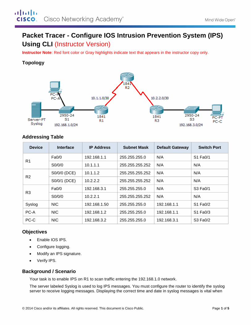
© 2014 Cisco and/or its affiliates. All rights reserved. This document is Cisco Public. Page 1 of 5
Packet Tracer - Configure IOS Intrusion Prevention System (IPS)
Using CLI (Instructor Version) Instructor Note: Red font color or Gray highlights indicate text that appears in the instructor copy only.
Topology
Addressing Table
Device Interface IP Address Subnet Mask Default Gateway Switch Port
R1 Fa0/0 192.168.1.1 255.255.255.0 N/A S1 Fa0/1
S0/0/0 10.1.1.1 255.255.255.252 N/A N/A
R2 S0/0/0 (DCE) 10.1.1.2 255.255.255.252 N/A N/A
S0/0/1 (DCE) 10.2.2.2 255.255.255.252 N/A N/A
R3 Fa0/0 192.168.3.1 255.255.255.0 N/A S3 Fa0/1
S0/0/0 10.2.2.1 255.255.255.252 N/A N/A
Syslog NIC 192.168.1.50 255.255.255.0 192.168.1.1 S1 Fa0/2
PC-A NIC 192.168.1.2 255.255.255.0 192.168.1.1 S1 Fa0/3
PC-C NIC 192.168.3.2 255.255.255.0 192.168.3.1 S3 Fa0/2
Objectives
Enable IOS IPS.
Configure logging.
Modify an IPS signature.
Verify IPS.
Background / Scenario
Your task is to enable IPS on R1 to scan traffic entering the 192.168.1.0 network.
The server labeled Syslog is used to log IPS messages. You must configure the router to identify the syslog server to receive logging messages. Displaying the correct time and date in syslog messages is vital when
Packet Tracer - Configure IOS Intrusion Prevention System (IPS) using CLI
© 2014 Cisco and/or its affiliates. All rights reserved. This document is Cisco Public. Page 2 of 5
using syslog to monitor the network. Set the clock and configure timestamp service for logging on the routers. Finally, enable IPS to produce an alert and drop ICMP echo reply packets inline.
The server and PCs have been preconfigured. The routers have also been preconfigured with the following:
o Enable password: ciscoenpa55
o Console password: ciscoconpa55
o VTY line password: ciscovtypa55
o OSPF 101
Part 1: Enable IOS IPS
Note: Within Packet Tracer, the routers already have the signature files imported and in place. They are the default xml files in flash. For this reason, it is not necessary to configure the public crypto key and complete a manual import of the signature files.
Step 1: Verify network connectivity.
a. Ping from PC-C to PC-A. The ping should be successful.
b. Ping from PC-A to PC-C. The ping should be successful.
Step 2: Create an IOS IPS configuration directory in flash.
On R1, create a directory in flash using the mkdir command. Name the directory ipsdir.
R1# mkdir ipsdir
Create directory filename [ipsdir]? <Enter>
Created dir flash:ipsdir
Step 3: Configure the IPS signature storage location.
On R1, configure the IPS signature storage location to be the directory you just created.
R1(config)# ip ips config location flash:ipsdir
Step 4: Create an IPS rule.
On R1, create an IPS rule name using the ip ips name name command in global configuration mode. Name the IPS rule iosips.
R1(config)# ip ips name iosips
Step 5: Enable logging.
IOS IPS supports the use of syslog to send event notification. Syslog notification is enabled by default. If logging console is enabled, IPS syslog messages display.
a. Enable syslog if it is not enabled.
R1(config)# ip ips notify log
b. If necessary, use the clock set command from privileged EXEC mode to reset the clock.
R1# clock set 10:20:00 10 january 2014
c. Verify that the timestamp service for logging is enabled on the router using the show run command. Enable the timestamp service if it is not enabled.
R1(config)# service timestamps log datetime msec
d. Send log messages to the syslog server at IP address 192.168.1.50.
Packet Tracer - Configure IOS Intrusion Prevention System (IPS) using CLI
© 2014 Cisco and/or its affiliates. All rights reserved. This document is Cisco Public. Page 3 of 5
R1(config)# logging host 192.168.1.50
Step 6: Configure IOS IPS to use the signature categories.
Retire the all signature category with the retired true command (all signatures within the signature release). Unretire the IOS_IPS Basic category with the retired false command.
R1(config)# ip ips signature-category
R1(config-ips-category)# category all
R1(config-ips-category-action)# retired true
R1(config-ips-category-action)# exit
R1(config-ips-category)# category ios_ips basic
R1(config-ips-category-action)# retired false
R1(config-ips-category-action)# exit
R1(config-ips-cateogry)# exit
Do you want to accept these changes? [confirm] <Enter>
Step 7: Apply the IPS rule to an interface.
Apply the IPS rule to an interface with the ip ips name direction command in interface configuration mode. Apply the rule outbound on the Fa0/0 interface of R1. After you enable IPS, some log messages will be sent to the console line indicating that the IPS engines are being initialized.
Note: The direction in means that IPS inspects only traffic going into the interface. Similarly, out means only traffic going out the interface.
R1(config)# interface fa0/0
R1(config-if)# ip ips iosips out
Part 2: Modify the Signature
Step 1: Change the event-action of a signature.
Un-retire the echo request signature (signature 2004, subsig ID 0), enable it, and change the signature action to alert and drop.
R1(config)# ip ips signature-definition
R1(config-sigdef)# signature 2004 0
R1(config-sigdef-sig)# status
R1(config-sigdef-sig-status)# retired false
R1(config-sigdef-sig-status)# enabled true
R1(config-sigdef-sig-status)# exit
R1(config-sigdef-sig)# engine
R1(config-sigdef-sig-engine)# event-action produce-alert
R1(config-sigdef-sig-engine)# event-action deny-packet-inline
R1(config-sigdef-sig-engine)# exit
R1(config-sigdef-sig)# exit
R1(config-sigdef)# exit
Do you want to accept these changes? [confirm] <Enter>
Step 2: Use show commands to verify IPS.
Use the show ip ips all command to view the IPS configuration status summary.
Packet Tracer - Configure IOS Intrusion Prevention System (IPS) using CLI
© 2014 Cisco and/or its affiliates. All rights reserved. This document is Cisco Public. Page 4 of 5
To which interfaces and in which direction is the iosips rule applied?
_______________________________________________________________________________________
Fa0/0 outbound.
Step 3: Verify that IPS is working properly.
a. From PC-C, attempt to ping PC-A. Were the pings successful? Why or why not?
____________________________________________________________________________________
____________________________________________________________________________________
The pings should fail. This is because the IPS rule for event-action of an echo request was set to “deny-packet-inline”.
b. From PC-A, attempt to ping PC-C. Were the pings successful? Why or why not?
____________________________________________________________________________________
____________________________________________________________________________________
The ping should be successful. This is because the IPS rule does not cover echo reply. When PC-A pings PC-C, PC-C responds with an echo reply.
Step 4: View the syslog messages.
a. Click the Syslog server.
b. Select the Services tab.
c. In the left navigation menu, select SYSLOG to view the log file.
Step 5: Check results.
Your completion percentage should be 100%. Click Check Results to see feedback and verification of which required components have been completed.
!!!Scritpt for R1
clock set 10:20:00 10 january 2014
mkdir ipsdir
config t
ip ips config location flash:ipsdir
ip ips name iosips
ip ips notify log
service timestamps log datetime msec
logging host 192.168.1.50
ip ips signature-category
category all
retired true
exit
category ios_ips basic
retired false
exit
exit
Packet Tracer - Configure IOS Intrusion Prevention System (IPS) using CLI
© 2014 Cisco and/or its affiliates. All rights reserved. This document is Cisco Public. Page 5 of 5
interface fa0/0
ip ips iosips out
exit
ip ips signature-definition
signature 2004 0
status
retired false
enabled true
exit
engine
event-action produce-alert
event-action deny-packet-inline
exit
exit
exit
© 2014 Cisco and/or its affiliates. All rights reserved. This document is Cisco Public. Page 1 of 6
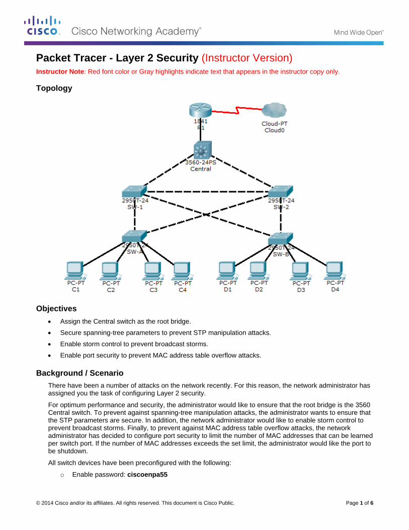
Packet Tracer - Layer 2 Security (Instructor Version) Instructor Note: Red font color or Gray highlights indicate text that appears in the instructor copy only.
Topology
Objectives
Assign the Central switch as the root bridge.
Secure spanning-tree parameters to prevent STP manipulation attacks.
Enable storm control to prevent broadcast storms.
Enable port security to prevent MAC address table overflow attacks.
Background / Scenario
There have been a number of attacks on the network recently. For this reason, the network administrator has assigned you the task of configuring Layer 2 security.
For optimum performance and security, the administrator would like to ensure that the root bridge is the 3560 Central switch. To prevent against spanning-tree manipulation attacks, the administrator wants to ensure that the STP parameters are secure. In addition, the network administrator would like to enable storm control to prevent broadcast storms. Finally, to prevent against MAC address table overflow attacks, the network administrator has decided to configure port security to limit the number of MAC addresses that can be learned per switch port. If the number of MAC addresses exceeds the set limit, the administrator would like the port to be shutdown.
All switch devices have been preconfigured with the following:
o Enable password: ciscoenpa55
Packet Tracer - Layer 2 Security
© 2014 Cisco and/or its affiliates. All rights reserved. This document is Cisco Public. Page 2 of 6
o Console password: ciscoconpa55
o VTY line password: ciscovtypa55
Part 1: Configure Root Bridge
Step 1: Determine the current root bridge.
From Central, issue the show spanning-tree command to determine the current root bridge and to see the ports in use and their status.
Which switch is the current root bridge?
_______________________________________________________________________________________
Current root is SW-1
Based on the current root bridge, what is the resulting spanning tree? (Draw the spanning-tree topology.)
Step 2: Assign Central as the primary root bridge.
Using the spanning-tree vlan 1 root primary command, assign Central as the root bridge.
Central(config)# spanning-tree vlan 1 root primary
Step 3: Assign SW-1 as a secondary root bridge.
Assign SW-1 as the secondary root bridge using the spanning-tree vlan 1 root secondary command.
SW-1(config)# spanning-tree vlan 1 root secondary
Step 4: Verify the spanning-tree configuration.
Issue the show spanning-tree command to verify that Central is the root bridge.
Which switch is the current root bridge?
_______________________________________________________________________________________
Current root is Central
Based on the new root-bridge, what is the resulting spanning tree? (Draw the spanning-tree topology.)
Part 2: Protect Against STP Attacks
Secure the STP parameters to prevent STP manipulation attacks.
Step 1: Enable PortFast on all access ports.
PortFast is configured on access ports that connect to a single workstation or server to enable them to become active more quickly. On the connected access ports of the SW-A and SW-B, use the spanning-tree portfast command.
SW-A(config)# interface range fastethernet 0/1 - 4
SW-A(config-if-range)# spanning-tree portfast
SW-B(config)# interface range fastethernet 0/1 - 4
SW-B(config-if-range)# spanning-tree portfast
Packet Tracer - Layer 2 Security
© 2014 Cisco and/or its affiliates. All rights reserved. This document is Cisco Public. Page 3 of 6
Step 2: Enable BPDU guard on all access ports.
BPDU guard is a feature that can help prevent rogue switches and spoofing on access ports. Enable BPDU guard on SW-A and SW-B access ports.
SW-A(config)# interface range fastethernet 0/1 - 4
SW-A(config-if-range)# spanning-tree bpduguard enable
SW-B(config)# interface range fastethernet 0/1 - 4
SW-B(config-if-range)# spanning-tree bpduguard enable
Note: Spanning-tree BPDU guard can be enabled on each individual port using the spanning-tree bpduguard enable command in the interface configuration mode or the spanning-tree portfast bpduguard default command in the global configuration mode. For grading purposes in this activity, please use the spanning-tree bpduguard enable command.
Step 3: Enable root guard.
Root guard can be enabled on all ports on a switch that are not root ports. It is best deployed on ports that connect to other non-root switches. Use the show spanning-tree command to determine the location of the root port on each switch.
On SW-1, enable root guard on ports Fa0/23 and Fa0/24. On SW-2, enable root guard on ports Fa0/23 and Fa0/24.
SW-1(config)# interface range fa0/23 - 24
SW-1(config-if-range)# spanning-tree guard root
SW-2(config)# interface range fa0/23 - 24
SW-2(config-if-range)# spanning-tree guard root
Part 3: Enable Storm Control
Step 1: Enable storm control for broadcasts.
a. Enable storm control for broadcasts on all ports connecting switches (trunk ports).
b. Enable storm control on interfaces connecting Central, SW-1, and SW-2. Set a 50 percent rising suppression level using the storm-control broadcast command.
SW-1(config)# interface range gi1/1 , fa0/1 , fa0/23 - 24
SW-1(config-if)# storm-control broadcast level 50
SW-2(config)# interface range gi1/1 , fa0/1 , fa0/23 - 24
SW-2(config-if)# storm-control broadcast level 50
Central(config-if)# interface range gi0/1 , gi0/2 , fa0/1
Central(config-if)# storm-control broadcast level 50
Step 2: Verify storm control configuration.
Verify your configuration with the show storm-control broadcast and the show run commands.
Packet Tracer - Layer 2 Security
© 2014 Cisco and/or its affiliates. All rights reserved. This document is Cisco Public. Page 4 of 6
Part 4: Configure Port Security and Disable Unused Ports
Step 1: Configure basic port security on all ports connected to host devices.
This procedure should be performed on all access ports on SW-A and SW-B. Set the maximum number of learned MAC address to 2, allow the MAC address to be learned dynamically, and set the violation to shutdown.
Note: A switch port must be configured as an access port to enable port security.
SW-A(config)# interface range fa0/1 - 22
SW-A(config-if-range)# switchport mode access
SW-A(config-if-range)# switchport port-security
SW-A(config-if-range)# switchport port-security maximum 2
SW-A(config-if-range)# switchport port-security violation shutdown
SW-A(config-if-range)# switchport port-security mac-address sticky
SW-B(config)# interface range fa0/1 - 22
SW-B(config-if-range)# switchport mode access
SW-B(config-if-range)# switchport port-security
SW-B(config-if-range)# switchport port-security maximum 2
SW-B(config-if-range)# switchport port-security violation shutdown
SW-B(config-if-range)# switchport port-security mac-address sticky
Why would you not want to enable port security on ports connected to other switches or routers?
_______________________________________________________________________________________
_______________________________________________________________________________________
_______________________________________________________________________________________
_______________________________________________________________________________________
_______________________________________________________________________________________
Ports connected to other switch devices and routers can, and should, have a multitude of MAC addresses learned for that single port. Limiting the number of MAC addresses that can be learned on these ports can significantly impact network functionality.
Step 2: Verify port security.
On SW-A, issue the show port-security interface fa0/1 command to verify that port security has been configured.
Step 3: Disable unused ports.
Disable all ports that are currently unused.
SW-A(config)# interface range fa0/5 - 22
SW-A(config-if-range)# shutdown
SW-B(config)# interface range fa0/5 - 22
SW-B(config-if-range)# shutdown
Packet Tracer - Layer 2 Security
© 2014 Cisco and/or its affiliates. All rights reserved. This document is Cisco Public. Page 5 of 6
Step 4: Check results.
Your completion percentage should be 100%. Click Check Results to see feedback and verification of which required components have been completed.
!!!Script for Central
conf t
spanning-tree vlan 1 root primary
interface range gi0/1 , gi0/2 , fa0/1
storm-control broadcast level 50
end
!!!Script for SW-1
conf t
spanning-tree vlan 1 root secondary
interface range fa0/23 - 24
spanning-tree guard root
interface range gi1/1 , fa0/1 , fa0/23 - 24
storm-control broadcast level 50
end
!!!Script for SW-2
conf t
interface range fa0/23 - 24
spanning-tree guard root
interface range gi1/1 , fa0/1 , fa0/23 - 24
storm-control broadcast level 50
end
!!!Script for SW-A
conf t
interface range fastethernet 0/1 - 4
spanning-tree portfast
spanning-tree bpduguard enable
interface range fa0/1 - 22
switchport mode access
switchport port-security
switchport port-security maximum 2
switchport port-security violation shutdown
switchport port-security mac-address sticky
interface range fa0/5 - 22
shutdown
end
!!!Script for SW-B
conf t
interface range fastethernet 0/1 - 4
spanning-tree portfast
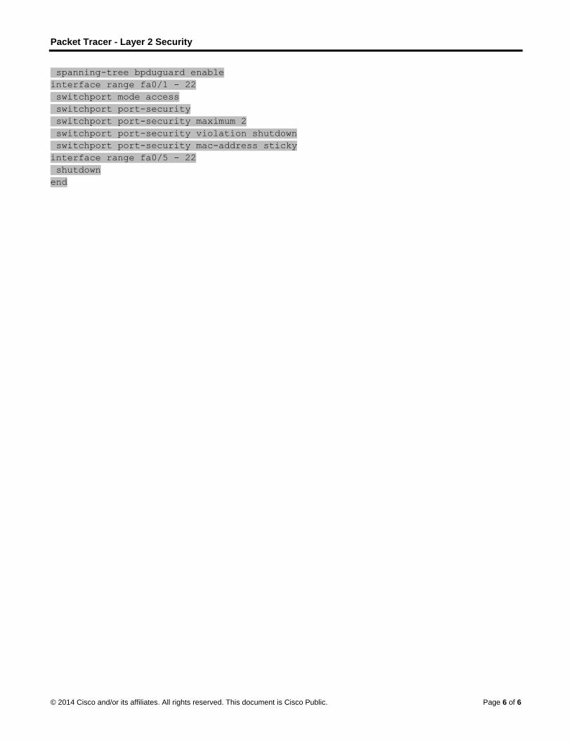
Packet Tracer - Layer 2 Security
© 2014 Cisco and/or its affiliates. All rights reserved. This document is Cisco Public. Page 6 of 6
spanning-tree bpduguard enable
interface range fa0/1 - 22
switchport mode access
switchport port-security
switchport port-security maximum 2
switchport port-security violation shutdown
switchport port-security mac-address sticky
interface range fa0/5 - 22
shutdown
end
© 2014 Cisco and/or its affiliates. All rights reserved. This document is Cisco Public. Page 1 of 6
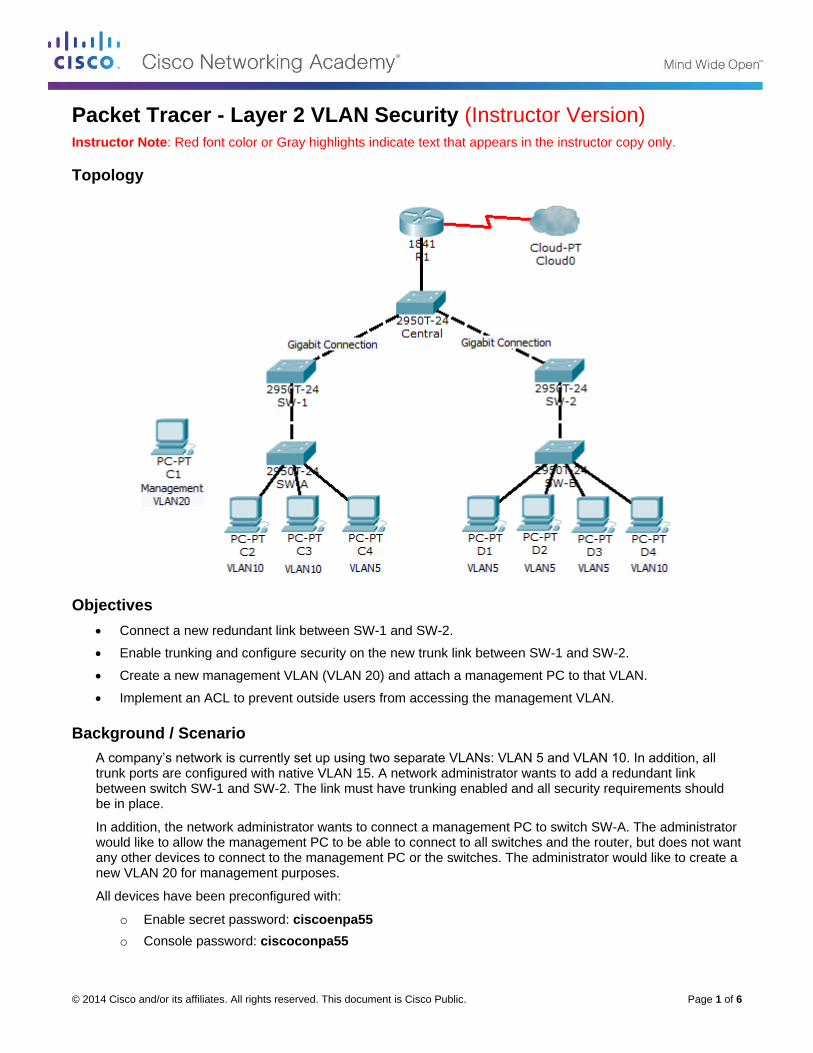
Packet Tracer - Layer 2 VLAN Security (Instructor Version) Instructor Note: Red font color or Gray highlights indicate text that appears in the instructor copy only.
Topology
Objectives
Connect a new redundant link between SW-1 and SW-2.
Enable trunking and configure security on the new trunk link between SW-1 and SW-2.
Create a new management VLAN (VLAN 20) and attach a management PC to that VLAN.
Implement an ACL to prevent outside users from accessing the management VLAN.
Background / Scenario
A company’s network is currently set up using two separate VLANs: VLAN 5 and VLAN 10. In addition, all trunk ports are configured with native VLAN 15. A network administrator wants to add a redundant link between switch SW-1 and SW-2. The link must have trunking enabled and all security requirements should be in place.
In addition, the network administrator wants to connect a management PC to switch SW-A. The administrator would like to allow the management PC to be able to connect to all switches and the router, but does not want any other devices to connect to the management PC or the switches. The administrator would like to create a new VLAN 20 for management purposes.
All devices have been preconfigured with:
o Enable secret password: ciscoenpa55
o Console password: ciscoconpa55
Packet Tracer - Layer 2 VLAN Security
© 2014 Cisco and/or its affiliates. All rights reserved. This document is Cisco Public. Page 2 of 6
o VTY line password: ciscovtypa55
Part 1: Verify Connectivity
Step 1: Verify connectivity between C2 (VLAN 10) and C3 (VLAN 10).
Step 2: Verify connectivity between C2 (VLAN 10) and D1 (VLAN 5).
Note: If using the simple PDU GUI packet, be sure to ping twice to allow for ARP.
Part 2: Create a Redundant Link Between SW-1 and SW-2
Step 1: Connect SW-1 and SW-2.
Using a crossover cable, connect port Fa0/23 on SW-1 to port Fa0/23 on SW-2.
Step 2: Enable trunking, including all trunk security mechanisms on the link between SW-1 and SW-2.
Trunking has already been configured on all pre-existing trunk interfaces. The new link must be configured for trunking, including all trunk security mechanisms. On both SW-1 and SW-2, set the port to trunk, assign native VLAN 15 to the trunk port, and disable auto-negotiation.
SW-1(config)# interface fa0/23
SW-1(config-if)# switchport mode trunk
SW-1(config-if)# switchport trunk native vlan 15
SW-1(config-if)# switchport nonegotiate
SW-1(config-if)# no shutdown
SW-2(config)# interface fa0/23
SW-2(config-if)# switchport mode trunk
SW-2(config-if)# switchport trunk native vlan 15
SW-2(config-if)# switchport nonegotiate
SW-2(config-if)# no shutdown
Part 3: Enable VLAN 20 as a Management VLAN
The network administrator wants to access all switch and routing devices using a management PC. For security, the administrator wants to ensure that all managed devices are on a separate VLAN.
Step 1: Enable a management VLAN (VLAN 20) on SW-A.
a. Enable VLAN 20 on SW-A.
SW-A(config)# vlan 20
SW-A(config-vlan)# exit
b. Create an interface VLAN 20 and assign an IP address within the 192.168.20.0/24 network.
SW-A(config)# interface vlan 20
SW-A(config-if)# ip address 192.168.20.1 255.255.255.0
Step 2: Enable the same management VLAN on all other switches.
a. Create the management VLAN on all switches: SW-B, SW-1, SW-2, and Central.
Packet Tracer - Layer 2 VLAN Security
© 2014 Cisco and/or its affiliates. All rights reserved. This document is Cisco Public. Page 3 of 6
SW-B(config)# vlan 20
SW-B(config-vlan)# exit
SW-1(config)# vlan 20
SW-1(config-vlan)# exit
SW-2(config)# vlan 20
SW-2(config-vlan)# exit
Central(config)# vlan 20
Central(config-vlan)# exit
b. Create an interface VLAN 20 on all switches and assign an IP address within the 192.168.20.0/24 network.
SW-B(config)# interface vlan 20
SW-B(config-if)# ip address 192.168.20.2 255.255.255.0
SW-1(config)# interface vlan 20
SW-1(config-if)# ip address 192.168.20.3 255.255.255.0
SW-2(config)# interface vlan 20
SW-2(config-if)# ip address 192.168.20.4 255.255.255.0
Central(config)# interface vlan 20
Central(config-if)# ip address 192.168.20.5 255.255.255.0
Step 3: Configure the management PC and connect it to SW-A port Fa0/1.
Ensure that the management PC is assigned an IP address within the 192.168.20.0/24 network. Connect the management PC to SW-A port Fa0/1.
Step 4: On SW-A, ensure the management PC is part of VLAN 20.
Interface Fa0/1 must be part of VLAN 20.
SW-A(config)# interface fa0/1
SW-A(config-if)# switchport access vlan 20
SW-A(config-if)# no shutdown
Step 5: Verify connectivity of the management PC to all switches.
The management PC should be able to ping SW-A, SW-B, SW-1, SW-2, and Central.
Part 4: Enable the Management PC to Access Router R1
Step 1: Enable a new subinterface on router R1.
a. Create subinterface Fa0/0.3 and set encapsulation to dot1q 20 to account for VLAN 20.
R1(config)# interface fa0/0.3
R1(config-subif)# encapsulation dot1q 20
Packet Tracer - Layer 2 VLAN Security
© 2014 Cisco and/or its affiliates. All rights reserved. This document is Cisco Public. Page 4 of 6
b. Assign an IP address within the 192.168.20.0/24 network.
R1(config)# interface fa0/0.3
R1(config-subif)# ip address 192.168.20.100 255.255.255.0
Step 2: Verify connectivity between the management PC and R1.
Be sure to configure the default gateway on the management PC to allow for connectivity.
Step 3: Enable security.
While the management PC must be able to access the router, no other PC should be able to access the management VLAN.
a. Create an ACL that denies any network from accessing the 192.168.20.0/24 network, but permits all other networks to access one another.
Example: (may vary from student configuration)
R1(config)# access-list 101 deny ip any 192.168.20.0 0.0.0.255
R1(config)# access-list 101 permit ip any any
b. Apply the ACL to the proper interface(s).
Example: (may vary from student configuration)
R1(config)# interface fa0/0.1
R1(config-subif)# ip access-group 101 in
R1(config-subif)# interface fa0/0.2
R1(config-subif)# ip access-group 101 in
Note: There are multiple ways in which an ACL can be created to accomplish the necessary security. For this reason, grading on this portion of the activity is based on the correct connectivity requirements. The management PC must be able to connect to all switches and the router. All other PCs should not be able to connect to any devices within the management VLAN.
Step 4: Verify security.
a. From the management PC, ping SW-A, SW-B, and R1. Were the pings successful? Explain.
____________________________________________________________________________________
____________________________________________________________________________________
____________________________________________________________________________________
The pings should have been successful because all devices within the 192.168.20.0 network should be able to ping one another. Devices within VLAN20 are not required to route through the router.
b. From D1, ping the management PC. Were the pings successful? Explain.
____________________________________________________________________________________
____________________________________________________________________________________
____________________________________________________________________________________
The ping should have failed. This is because in order for a device within a different VLAN to successfully ping a device within VLAN20, it must be routed. The router has an ACL that prevents all packets from accessing the 192.168.20.0 network.
Packet Tracer - Layer 2 VLAN Security
© 2014 Cisco and/or its affiliates. All rights reserved. This document is Cisco Public. Page 5 of 6
Step 5: Check results.
Your completion percentage should be 100%. Click Check Results to see feedback and verification of which required components have been completed.
If all components appear to be correct and the activity still shows incomplete, it could be due to the connectivity tests that verify the ACL operation.
!!! Script for SW-1
conf t
interface fa0/23
switchport mode trunk
switchport trunk native vlan 15
switchport nonegotiate
no shutdown
vlan 20
exit
interface vlan 20
ip address 192.168.20.3 255.255.255.0
!!! Script for SW-2
conf t
interface fa0/23
switchport mode trunk
switchport trunk native vlan 15
switchport nonegotiate
no shutdown
vlan 20
exit
interface vlan 20
ip address 192.168.20.4 255.255.255.0
!!! Script for SW-A
conf t
vlan 20
exit
interface vlan 20
ip address 192.168.20.1 255.255.255.0
interface fa0/1
switchport access vlan 20
no shutdown
!!! Script for SW-B
conf t
vlan 20
exit
interface vlan 20
ip address 192.168.20.2 255.255.255.0
Packet Tracer - Layer 2 VLAN Security
© 2014 Cisco and/or its affiliates. All rights reserved. This document is Cisco Public. Page 6 of 6
!!! Script for Central
conf t
vlan 20
exit
interface vlan 20
ip address 192.168.20.5 255.255.255.0
!!! Script for R1
conf t
interface fa0/0.3
encapsulation dot1q 20
ip address 192.168.20.100 255.255.255.0
access-list 101 deny ip any 192.168.20.0 0.0.0.255
access-list 101 permit ip any any
interface FastEthernet0/0.1
ip access-group 101 in
interface FastEthernet0/0.2
ip access-group 101 in
© 2014 Cisco and/or its affiliates. All rights reserved. This document is Cisco Public. Page 1 of 5
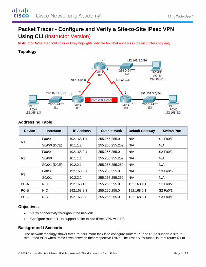
Packet Tracer - Configure and Verify a Site-to-Site IPsec VPN
Using CLI (Instructor Version) Instructor Note: Red font color or Gray highlights indicate text that appears in the instructor copy only.
Topology
Addressing Table
Device Interface IP Address Subnet Mask Default Gateway Switch Port
R1 Fa0/0 192.168.1.1 255.255.255.0 N/A S1 Fa0/1
S0/0/0 (DCE) 10.1.1.2 255.255.255.252 N/A N/A
R2
Fa0/0 192.168.2.1 255.255.255.0 N/A S2 Fa0/2
S0/0/0 10.1.1.1 255.255.255.252 N/A N/A
S0/0/1 (DCE) 10.2.2.1 255.255.255.252 N/A N/A
R3 Fa0/0 192.168.3.1 255.255.255.0 N/A S3 Fa0/5
S0/0/1 10.2.2.2 255.255.255.252 N/A N/A
PC-A NIC 192.168.1.3 255.255.255.0 192.168.1.1 S1 Fa0/2
PC-B NIC 192.168.2.3 255.255.255.0 192.168.2.1 S2 Fa0/1
PC-C NIC 192.168.3.3 255.255.255.0 192.168.3.1 S3 Fa0/18
Objectives
Verify connectivity throughout the network.
Configure router R1 to support a site-to-site IPsec VPN with R3.
Background / Scenario
The network topology shows three routers. Your task is to configure routers R1 and R3 to support a site-to-site IPsec VPN when traffic flows between their respective LANs. The IPsec VPN tunnel is from router R1 to
Packet Tracer - Configure and Verify a Site-to-Site IPsec VPN Using CLI
© 2014 Cisco and/or its affiliates. All rights reserved. This document is Cisco Public. Page 2 of 5
router R3 via R2. R2 acts as a pass-through and has no knowledge of the VPN. IPsec provides secure transmission of sensitive information over unprotected networks, such as the Internet. IPsec operates at the network layer, protecting and authenticating IP packets between participating IPsec devices (peers), such as Cisco routers.
ISAKMP Phase 1 Policy Parameters
Parameters R1 R3
Key distribution method Manual or ISAKMP ISAKMP ISAKMP
Encryption algorithm DES, 3DES, or AES AES AES
Hash algorithm MD5 or SHA-1 SHA-1 SHA-1
Authentication method Pre-shared keys or RSA pre-share pre-share
Key exchange DH Group 1, 2, or 5 DH 2 DH 2
IKE SA Lifetime 86400 seconds or less 86400 86400
ISAKMP Key vpnpa55 vpnpa55
Note: Bolded parameters are defaults. Only unbolded parameters have to be explicitly configured.
IPsec Phase 2 Policy Parameters
Parameters R1 R3
Transform Set VPN-SET VPN-SET
Peer Hostname R3 R1
Peer IP Address 10.2.2.2 10.1.1.2
Network to be encrypted 192.168.1.0/24 192.168.3.0/24
Crypto Map name VPN-MAP VPN-MAP
SA Establishment ipsec-isakmp ipsec-isakmp
The routers have been pre-configured with the following:
o Password for console line: ciscoconpa55
o Password for vty lines: ciscovtypa55
o Enable password: ciscoenpa55
o RIP version 2
Part 1: Configure IPsec Parameters on R1
Step 1: Test connectivity.
Ping from PC-A to PC-C.
Step 2: Identify interesting traffic on R1.
Configure ACL 110 to identify the traffic from the LAN on R1 to the LAN on R3 as interesting. This interesting traffic will trigger the IPsec VPN to be implemented whenever there is traffic between R1 to R3 LANs. All
Packet Tracer - Configure and Verify a Site-to-Site IPsec VPN Using CLI
© 2014 Cisco and/or its affiliates. All rights reserved. This document is Cisco Public. Page 3 of 5
other traffic sourced from the LANs will not be encrypted. Because of the implicit deny all, there is no need to configure a deny any any statement.
R1(config)# access-list 110 permit ip 192.168.1.0 0.0.0.255 192.168.3.0
0.0.0.255
Step 3: Configure the ISAKMP Phase 1 properties on R1.
Configure the crypto ISAKMP policy 10 properties on R1 along with the shared crypto key vpnpa55. Refer to the ISAKMP Phase 1 table for the specific parameters to configure. Default values do not have to be configured; therefore, only the encryption, key exchange method, and DH method must be configured.
R1(config)# crypto isakmp policy 10
R1(config-isakmp)# encryption aes
R1(config-isakmp)# authentication pre-share
R1(config-isakmp)# group 2
R1(config-isakmp)# exit
R1(config)# crypto isakmp key vpnpa55 address 10.2.2.2
Step 4: Configure the ISAKMP Phase 2 properties on R1.
a. Create the transform-set VPN-SET to use esp-3des and esp-sha-hmac.
R1(config)# crypto ipsec transform-set VPN-SET esp-3des esp-sha-hmac
b. Create the crypto map VPN-MAP that binds all of the Phase 2 parameters together. Use sequence number 10 and identify it as an ipsec-isakmp map.
R1(config)# crypto map VPN-MAP 10 ipsec-isakmp
R1(config-crypto-map)# description VPN connection to R3
R1(config-crypto-map)# set peer 10.2.2.2
R1(config-crypto-map)# set transform-set VPN-SET
R1(config-crypto-map)# match address 110
R1(config-crypto-map)# exit
Step 5: Configure the crypto map on the outgoing interface.
Bind the VPN-MAP crypto map to the outgoing Serial 0/0/0 interface.
R1(config)# interface S0/0/0
R1(config-if)# crypto map VPN-MAP
Part 2: Configure IPsec Parameters on R3
Step 1: Configure router R3 to support a site-to-site VPN with R1.
Now configure reciprocating parameters on R3. Configure ACL 110 identifying the traffic from the LAN on R3 to the LAN on R1 as interesting.
R3(config)# access-list 110 permit ip 192.168.3.0 0.0.0.255 192.168.1.0
0.0.0.255
Step 2: Configure the ISAKMP Phase 1 properties on R3.
Configure the crypto ISAKMP policy 10 properties on R3 along with the shared crypto key vpnpa55.
R3(config)# crypto isakmp policy 10
R3(config-isakmp)# encryption aes
Packet Tracer - Configure and Verify a Site-to-Site IPsec VPN Using CLI
© 2014 Cisco and/or its affiliates. All rights reserved. This document is Cisco Public. Page 4 of 5
R3(config-isakmp)# authentication pre-share
R3(config-isakmp)# group 2
R3(config-isakmp)# exit
R3(config)# crypto isakmp key vpnpa55 address 10.1.1.2
Step 3: Configure the ISAKMP Phase 2 properties on R1.
a. Like you did on R1, create the transform-set VPN-SET to use esp-3des and esp-sha-hmac.
R3(config)# crypto ipsec transform-set VPN-SET esp-3des esp-sha-hmac
b. Create the crypto map VPN-MAP that binds all of the Phase 2 parameters together. Use sequence number 10 and identify it as an ipsec-isakmp map.
R3(config)# crypto map VPN-MAP 10 ipsec-isakmp
R3(config-crypto-map)# description VPN connection to R1
R3(config-crypto-map)# set peer 10.1.1.2
R3(config-crypto-map)# set transform-set VPN-SET
R3(config-crypto-map)# match address 110
R3(config-crypto-map)# exit
Step 4: Configure the crypto map on the outgoing interface.
Bind the VPN-MAP crypto map to the outgoing Serial 0/0/1 interface. Note: This is not graded.
R3(config)# interface S0/0/1
R3(config-if)# crypto map VPN-MAP
Part 3: Verify the IPsec VPN
Step 1: Verify the tunnel prior to interesting traffic.
Issue the show crypto ipsec sa command on R1. Notice that the number of packets encapsulated, encrypted, decapsulated and decrypted are all set to 0.
Step 2: Create interesting traffic.
From PC-A, ping PC-C.
Step 3: Verify the tunnel after interesting traffic.
On R1, re-issue the show crypto ipsec sa command. Now notice that the number of packets is more than 0 indicating that the IPsec VPN tunnel is working.
Step 4: Create uninteresting traffic.
From PC-A, ping PC-B.
Step 5: Verify the tunnel.
On R1, re-issue the show crypto ipsec sa command. Notice that the number of packets has not changed verifying that uninteresting traffic is not encrypted.
Step 6: Check results.
Your completion percentage should be 100%. Click Check Results to see feedback and verification of which required components have been completed.
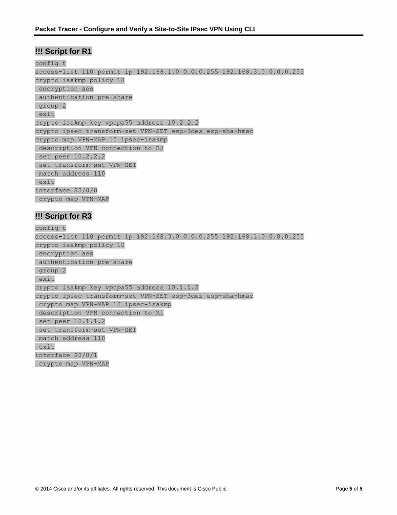
Packet Tracer - Configure and Verify a Site-to-Site IPsec VPN Using CLI
© 2014 Cisco and/or its affiliates. All rights reserved. This document is Cisco Public. Page 5 of 5
!!! Script for R1
config t
access-list 110 permit ip 192.168.1.0 0.0.0.255 192.168.3.0 0.0.0.255
crypto isakmp policy 10
encryption aes
authentication pre-share
group 2
exit
crypto isakmp key vpnpa55 address 10.2.2.2
crypto ipsec transform-set VPN-SET esp-3des esp-sha-hmac
crypto map VPN-MAP 10 ipsec-isakmp
description VPN connection to R3
set peer 10.2.2.2
set transform-set VPN-SET
match address 110
exit
interface S0/0/0
crypto map VPN-MAP
!!! Script for R3
config t
access-list 110 permit ip 192.168.3.0 0.0.0.255 192.168.1.0 0.0.0.255
crypto isakmp policy 10
encryption aes
authentication pre-share
group 2
exit
crypto isakmp key vpnpa55 address 10.1.1.2
crypto ipsec transform-set VPN-SET esp-3des esp-sha-hmac
crypto map VPN-MAP 10 ipsec-isakmp
description VPN connection to R1
set peer 10.1.1.2
set transform-set VPN-SET
match address 110
exit
interface S0/0/1
crypto map VPN-MAP
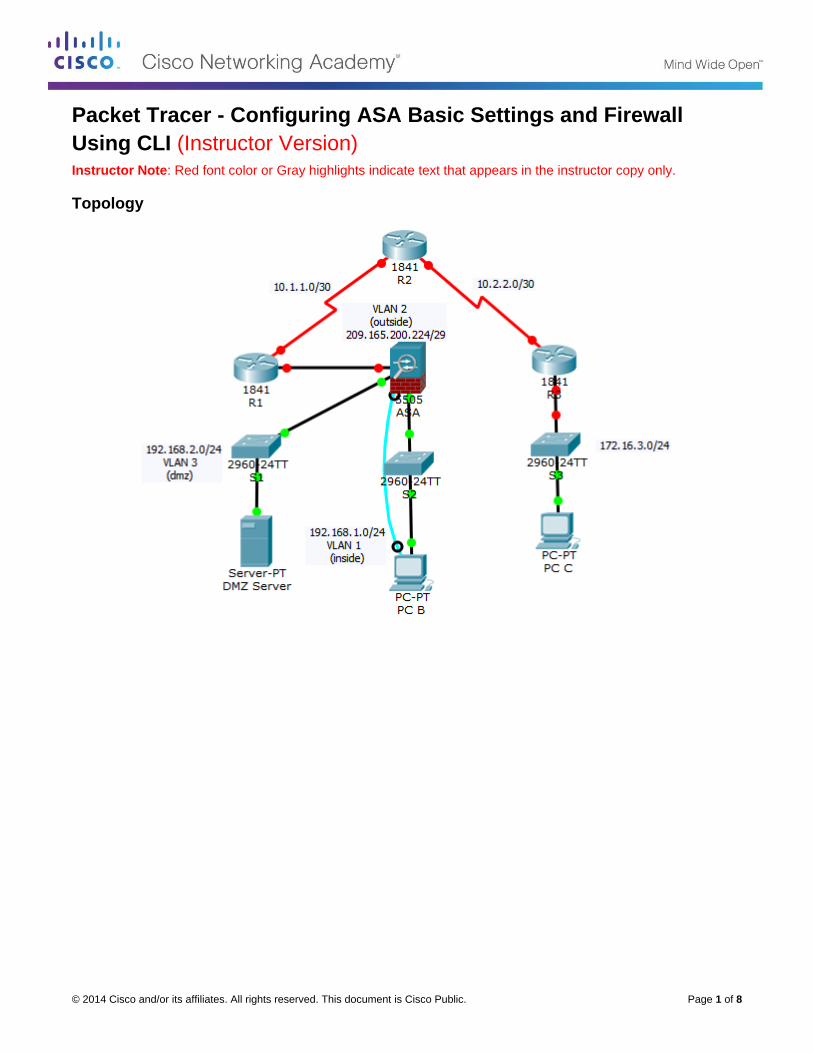
© 2014 Cisco and/or its affiliates. All rights reserved. This document is Cisco Public. Page 1 of 8
Packet Tracer - Configuring ASA Basic Settings and Firewall
Using CLI (Instructor Version) Instructor Note: Red font color or Gray highlights indicate text that appears in the instructor copy only.
Topology
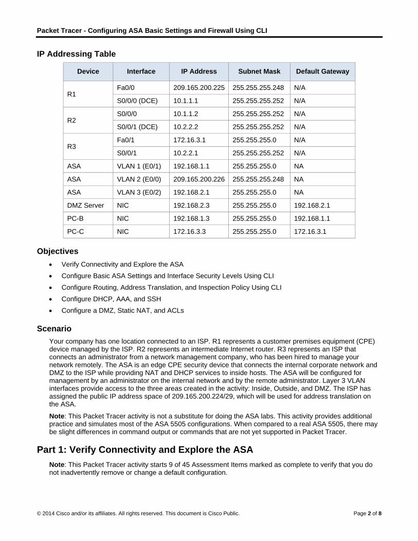
Packet Tracer - Configuring ASA Basic Settings and Firewall Using CLI
© 2014 Cisco and/or its affiliates. All rights reserved. This document is Cisco Public. Page 2 of 8
IP Addressing Table
Device Interface IP Address Subnet Mask Default Gateway
R1 Fa0/0 209.165.200.225 255.255.255.248 N/A
S0/0/0 (DCE) 10.1.1.1 255.255.255.252 N/A
R2 S0/0/0 10.1.1.2 255.255.255.252 N/A
S0/0/1 (DCE) 10.2.2.2 255.255.255.252 N/A
R3 Fa0/1 172.16.3.1 255.255.255.0 N/A
S0/0/1 10.2.2.1 255.255.255.252 N/A
ASA VLAN 1 (E0/1) 192.168.1.1 255.255.255.0 NA
ASA VLAN 2 (E0/0) 209.165.200.226 255.255.255.248 NA
ASA VLAN 3 (E0/2) 192.168.2.1 255.255.255.0 NA
DMZ Server NIC 192.168.2.3 255.255.255.0 192.168.2.1
PC-B NIC 192.168.1.3 255.255.255.0 192.168.1.1
PC-C NIC 172.16.3.3 255.255.255.0 172.16.3.1
Objectives
Verify Connectivity and Explore the ASA
Configure Basic ASA Settings and Interface Security Levels Using CLI
Configure Routing, Address Translation, and Inspection Policy Using CLI
Configure DHCP, AAA, and SSH
Configure a DMZ, Static NAT, and ACLs
Scenario
Your company has one location connected to an ISP. R1 represents a customer premises equipment (CPE) device managed by the ISP. R2 represents an intermediate Internet router. R3 represents an ISP that connects an administrator from a network management company, who has been hired to manage your network remotely. The ASA is an edge CPE security device that connects the internal corporate network and DMZ to the ISP while providing NAT and DHCP services to inside hosts. The ASA will be configured for management by an administrator on the internal network and by the remote administrator. Layer 3 VLAN interfaces provide access to the three areas created in the activity: Inside, Outside, and DMZ. The ISP has assigned the public IP address space of 209.165.200.224/29, which will be used for address translation on the ASA.
Note: This Packet Tracer activity is not a substitute for doing the ASA labs. This activity provides additional practice and simulates most of the ASA 5505 configurations. When compared to a real ASA 5505, there may be slight differences in command output or commands that are not yet supported in Packet Tracer.
Part 1: Verify Connectivity and Explore the ASA
Note: This Packet Tracer activity starts 9 of 45 Assessment Items marked as complete to verify that you do not inadvertently remove or change a default configuration.
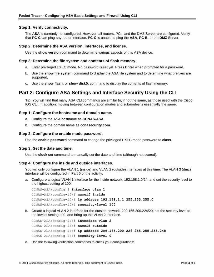
Packet Tracer - Configuring ASA Basic Settings and Firewall Using CLI
© 2014 Cisco and/or its affiliates. All rights reserved. This document is Cisco Public. Page 3 of 8
Step 1: Verify connectivity.
The ASA is currently not configured. However, all routers, PCs, and the DMZ Server are configured. Verify that PC-C can ping any router interface. PC-C is unable to ping the ASA, PC-B, or the DMZ Server.
Step 2: Determine the ASA version, interfaces, and license.
Use the show version command to determine various aspects of this ASA device.
Step 3: Determine the file system and contents of flash memory.
a. Enter privileged EXEC mode. No password is set yet. Press Enter when prompted for a password.
b. Use the show file system command to display the ASA file system and to determine what prefixes are supported.
c. Use the show flash: or show disk0: command to display the contents of flash memory.
Part 2: Configure ASA Settings and Interface Security Using the CLI
Tip: You will find that many ASA CLI commands are similar to, if not the same, as those used with the Cisco IOS CLI. In addition, moving between configuration modes and submodes is essentially the same.
Step 1: Configure the hostname and domain name.
a. Configure the ASA hostname as CCNAS-ASA.
b. Configure the domain name as ccnasecurity.com.
Step 2: Configure the enable mode password.
Use the enable password command to change the privileged EXEC mode password to class.
Step 3: Set the date and time.
Use the clock set command to manually set the date and time (although not scored).
Step 4: Configure the inside and outside interfaces.
You will only configure the VLAN 1 (inside) and VLAN 2 (outside) interfaces at this time. The VLAN 3 (dmz) interface will be configured in Part 6 of the activity.
a. Configure a logical VLAN 1 interface for the inside network, 192.168.1.0/24, and set the security level to the highest setting of 100.
CCNAS-ASA(config)# interface vlan 1
CCNAS-ASA(config-if)# nameif inside
CCNAS-ASA(config-if)# ip address 192.168.1.1 255.255.255.0
CCNAS-ASA(config-if)# security-level 100
b. Create a logical VLAN 2 interface for the outside network, 209.165.200.224/29, set the security level to the lowest setting of 0, and bring up the VLAN 2 interface.
CCNAS-ASA(config-if)# interface vlan 2
CCNAS-ASA(config-if)# nameif outside
CCNAS-ASA(config-if)# ip address 209.165.200.226 255.255.255.248
CCNAS-ASA(config-if)# security-level 0
c. Use the following verification commands to check your configurations:
Packet Tracer - Configuring ASA Basic Settings and Firewall Using CLI
© 2014 Cisco and/or its affiliates. All rights reserved. This document is Cisco Public. Page 4 of 8
1) Use the show interface ip brief command to display the status for all ASA interfaces. Note: This command is different from the IOS command show ip interface brief. If any of the physical or logical interfaces previously configured are not up/up, troubleshoot as necessary before continuing.
Tip: Most ASA show commands, including ping, copy, and others, can be issued from within any configuration mode prompt without the do command required with the IOS CLI.
2) Use the show ip address command to display the information for the Layer 3 VLAN interfaces.
3) Use the show switch vlan command to display the inside and outside VLANs configured on the ASA and to display the assigned ports.
Step 5: Test connectivity to the ASA.
a. You should be able to ping from PC-B to the ASA inside interface address (192.168.1.1). If the pings fail, troubleshoot the configuration as necessary.
b. From PC-B, ping the VLAN 2 (outside) interface at IP address 209.165.200.226. You should not be able to ping this address.
Part 3: Configure Routing, Address Translation, and Inspection Policy
Using the CLI
Step 1: Configure a static default route for the ASA.
To enable the ASA to reach external networks, you will configure a default static route on the ASA outside interface.
a. Create a “quad zero” default route using the route command, associate it with the ASA outside interface, and point to the R1 Fa0/0 IP address 209.165.200.225 as the gateway of last resort.
CCNAS-ASA(config)# route outside 0.0.0.0 0.0.0.0 209.165.200.225
b. Issue the show route command to verify the static default route is in the ASA routing table.
c. Verify the ASA can ping the R1 S0/0/0 IP address 10.1.1.1. If the ping is unsuccessful, troubleshoot, as necessary.
Step 2: Configure address translation using PAT and network objects.
a. Create network object inside-net and assign attributes to it using the subnet and nat commands.
CCNAS-ASA(config)# object network inside-net
CCNAS-ASA(config-network-object)# subnet 192.168.1.0 255.255.255.0
CCNAS-ASA(config-network-object)# nat (inside,outside) dynamic interface
CCNAS-ASA(config-network-object)# end
b. The ASA splits the configuration into the object portion that defines the network to be translated and the actual nat command parameters. These appear in two different places in the running configuration. Display the NAT object configuration using the show run command.
c. From PC-B attempt to ping the R1 Fa0/0 interface at IP address 209.165.200.225. The pings should fail.
d. Issue the show nat command on the ASA to see the translated and untranslated hits. Notice that, of the pings from PC-B, four were translated and four were not. The outgoing pings (echos) were translated and sent to the destination. The returning echo replies were blocked by the firewall policy. You will configure the default inspection policy to allow ICMP in the next step.
Packet Tracer - Configuring ASA Basic Settings and Firewall Using CLI
© 2014 Cisco and/or its affiliates. All rights reserved. This document is Cisco Public. Page 5 of 8
Step 3: Modify the default MPF application inspection global service policy.
For application layer inspection and other advanced options, the Cisco Modular Policy Framework (MPF) is available on ASAs.
The Packet Tracer ASA device does not have an MPF policy map in place, by default; therefore, as a modification, we can create the default policy map that will perform the inspection on inside-to-outside traffic. When configured correctly only traffic initiated from the inside is allowed back in to the outside interface. You will need to add ICMP to the inspection list.
a. Create the class-map, policy-map, and service-policy. Add the inspection of ICMP traffic to the policy map list using the following commands:
CCNAS-ASA(config)# class-map inspection_default
CCNAS-ASA(config-cmap)# match default-inspection-traffic
CCNAS-ASA(config-cmap)# exit
CCNAS-ASA(config)# policy-map global_policy
CCNAS-ASA(config-pmap)# class inspection_default
CCNAS-ASA(config-pmap-c)# inspect icmp
CCNAS-ASA(config-pmap-c)# exit
CCNAS-ASA(config)# service-policy global_policy global
b. From PC-B, attempt to ping the R1 Fa0/0 interface at IP address 209.165.200.225. The pings should be successful this time because ICMP traffic is now being inspected and legitimate return traffic is being allowed. If the pings fail, troubleshoot your configurations.
Part 4: Configure DHCP, AAA, and SSH
Step 1: Configure the ASA as a DHCP server.
a. Configure a DHCP address pool and enable it on the ASA inside interface.
CCNAS-ASA(config)# dhcpd address 192.168.1.5-192.168.1.36 inside
b. (Optional) Specify the IP address of the DNS server to be given to clients.
CCNAS-ASA(config)# dhcpd dns 209.165.201.2 interface inside
c. Enable the DHCP daemon within the ASA to listen for DHCP client requests on the enabled interface (inside).
CCNAS-ASA(config)# dhcpd enable inside
d. Change PC-B from a static IP address to a DHCP client, and verify that it receives IP addressing information. Troubleshoot, as necessary, to resolve any problems.
Step 2: Configure AAA to use the local database for authentication.
a. Define a local user named admin by entering the username command. Specify a password of cisco123.
CCNAS-ASA(config)# username admin password cisco123
b. Configure AAA to use the local ASA database for Telnet and SSH user authentication.
CCNAS-ASA(config)# aaa authentication ssh console LOCAL
CCNAS-ASA(config)# aaa authentication telnet console LOCAL
Packet Tracer - Configuring ASA Basic Settings and Firewall Using CLI
© 2014 Cisco and/or its affiliates. All rights reserved. This document is Cisco Public. Page 6 of 8
Step 3: Configure remote access to the ASA.
You can configure the ASA to accept connections from a single host or a range of hosts on the inside or outside network. In this step, hosts from the outside network can only use SSH to communicate with the ASA. SSH and Telnet sessions can be used access the ASA from the inside network.
a. Generate an RSA key pair, which is required to support SSH connections. Because the ASA device has RSA keys already in place, enter no when prompted to replace them.
CCNAS-ASA(config)# crypto key generate rsa modulus 1024
WARNING: You have a RSA keypair already defined named <Default-RSA-Key>.
Do you really want to replace them? [yes/no]: no
ERROR: Failed to create new RSA keys named <Default-RSA-Key>
b. Configure the ASA to allow Telnet connection from any host on the inside network 192.168.1.0/24. Set the Telnet session timeout to 10 minutes.
CCNAS-ASA(config)# telnet 192.168.1.0 255.255.255.0 inside
CCNAS-ASA(config)# telnet timeout 10
c. Configure the ASA to allow SSH connections from any host on the inside network 192.168.1.0/24 and from the remote management host at the branch office (172.16.3.3) on the outside network. Set the SSH timeout to 10 minutes (the default is 5 minutes).
CCNAS-ASA(config)# ssh 192.168.1.0 255.255.255.0 inside
CCNAS-ASA(config)# ssh 172.16.3.3 255.255.255.255 outside
CCNAS-ASA(config)# ssh timeout 10
Part 5: Configure a DMZ, Static NAT, and ACLs
R1 Fa0/0 and the ASA outside interface already use 209.165.200.225 and .226, respectively. You will use public address 209.165.200.227 and static NAT to provide address translation access to the server.
Step 1: Configure the DMZ interface VLAN 3 on the ASA.
a. Configure DMZ VLAN 3, which is where the public access web server will reside. Assign it IP address 192.168.2.1/24, name it dmz, and assign it a security level of 70. Because the server does not need to initiate communication with the inside users, disable forwarding to interface VLAN 1.
CCNAS-ASA(config)# interface vlan 3
CCNAS-ASA(config-if)# ip address 192.168.2.1 255.255.255.0
CCNAS-ASA(config-if)# no forward interface vlan 1
CCNAS-ASA(config-if)# nameif dmz
INFO: Security level for "dmz" set to 0 by default.
CCNAS-ASA(config-if)# security-level 70
b. Assign ASA physical interface E0/2 to DMZ VLAN 3 and enable the interface.
CCNAS-ASA(config-if)# interface Ethernet0/2
CCNAS-ASA(config-if)# switchport access vlan 3
c. Use the following verification commands to check your configurations:
1) Use the show interface ip brief command to display the status for all ASA interfaces.
2) Use the show ip address command to display the information for the Layer 3 VLAN interfaces.
Packet Tracer - Configuring ASA Basic Settings and Firewall Using CLI
© 2014 Cisco and/or its affiliates. All rights reserved. This document is Cisco Public. Page 7 of 8
3) Use the show switch vlan command to display the inside and outside VLANs configured on the ASA and to display the assigned ports.
Step 2: Configure static NAT to the DMZ server using a network object.
Configure a network object named dmz-server and assign it the static IP address of the DMZ server (192.168.2.3). While in object definition mode, use the nat command to specify that this object is used to translate a DMZ address to an outside address using static NAT, and specify a public translated address of 209.165.200.227.
CCNAS-ASA(config)# object network dmz-server
CCNAS-ASA(config-network-object)# host 192.168.2.3
CCNAS-ASA(config-network-object)# nat (dmz,outside) static 209.165.200.227
CCNAS-ASA(config-network-object)# exit
Step 3: Configure an ACL to allow access to the DMZ server from the Internet.
Configure a named access list OUTSIDE-DMZ that permits the TCP protocol on port 80 from any external host to the internal IP address of the DMZ server. Apply the access list to the ASA outside interface in the “IN” direction.
CCNAS-ASA(config)# access-list OUTSIDE-DMZ permit icmp any host 192.168.2.3
CCNAS-ASA(config)# access-list OUTSIDE-DMZ permit tcp any host 192.168.2.3 eq
80
CCNAS-ASA(config)# access-group OUTSIDE-DMZ in interface outside
Note: Unlike IOS ACLs, the ASA ACL permit statement must permit access to the internal private DMZ address. External hosts access the server using its public static NAT address, and the ASA translates it to the internal host IP address and applies the ACL.
Step 4: Test access to the DMZ server.
At the time this Packet Tracer activity was created, the ability to successfully test outside access to the DMZ web server was not in place; therefore, successful testing is not required.
Step 5: Check results.
Your completion percentage should be 100%. Click Check Results to see feedback and verification of which required components have been completed.
Scripts
ASA
enable
!<Enter> for password
conf t
hostname CCNAS-ASA
domain-name ccnasecurity.com
enable password class
clock set 13:12:51 June 30 2014
interface vlan 1
nameif inside
ip address 192.168.1.1 255.255.255.0
security-level 100
interface vlan 2
Packet Tracer - Configuring ASA Basic Settings and Firewall Using CLI
© 2014 Cisco and/or its affiliates. All rights reserved. This document is Cisco Public. Page 8 of 8
nameif outside
ip address 209.165.200.226 255.255.255.248
security-level 0
route outside 0.0.0.0 0.0.0.0 209.165.200.225
object network inside-net
subnet 192.168.1.0 255.255.255.0
nat (inside,outside) dynamic interface
class-map inspection_default
match default-inspection-traffic
exit
policy-map global_policy
class inspection_default
inspect icmp
exit
service-policy global_policy global
dhcpd address 192.168.1.5-192.168.1.36 inside
dhcpd dns 209.165.201.2 interface inside
dhcpd enable inside
username admin password cisco123
aaa authentication ssh console LOCAL
aaa authentication telnet console LOCAL
crypto key generate rsa modulus 1024
no
telnet 192.168.1.0 255.255.255.0 inside
telnet timeout 10
ssh 192.168.1.0 255.255.255.0 inside
ssh 172.16.3.3 255.255.255.255 outside
ssh timeout 10
interface vlan 3
ip address 192.168.2.1 255.255.255.0
no forward interface vlan 1
nameif dmz
security-level 70
interface Ethernet0/2
switchport access vlan 3
object network dmz-server
host 192.168.2.3
nat (dmz,outside) static 209.165.200.227
access-list OUTSIDE-DMZ permit icmp any host 192.168.2.3
access-list OUTSIDE-DMZ permit tcp any host 192.168.2.3 eq 80
access-group OUTSIDE-DMZ in interface outside
PC-B
-Change from static to DHCP addressing
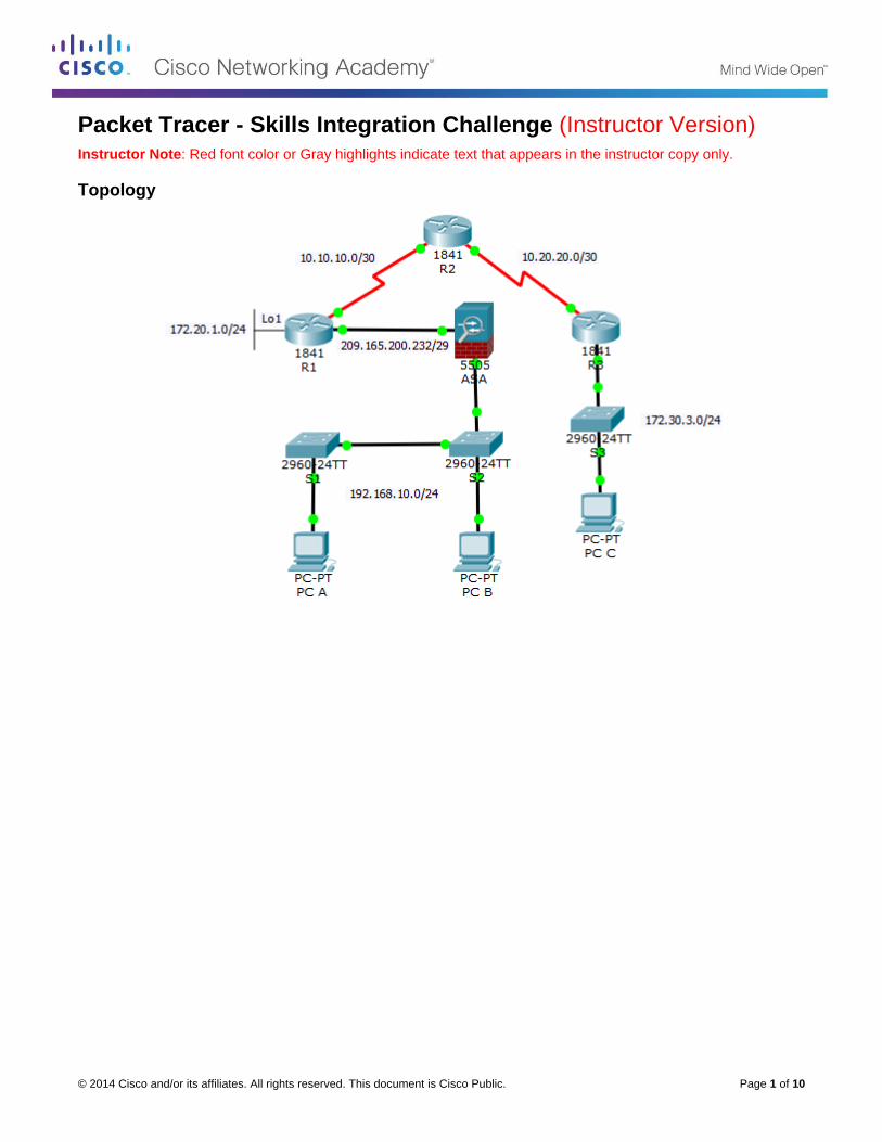
© 2014 Cisco and/or its affiliates. All rights reserved. This document is Cisco Public. Page 1 of 10
Packet Tracer - Skills Integration Challenge (Instructor Version) Instructor Note: Red font color or Gray highlights indicate text that appears in the instructor copy only.
Topology
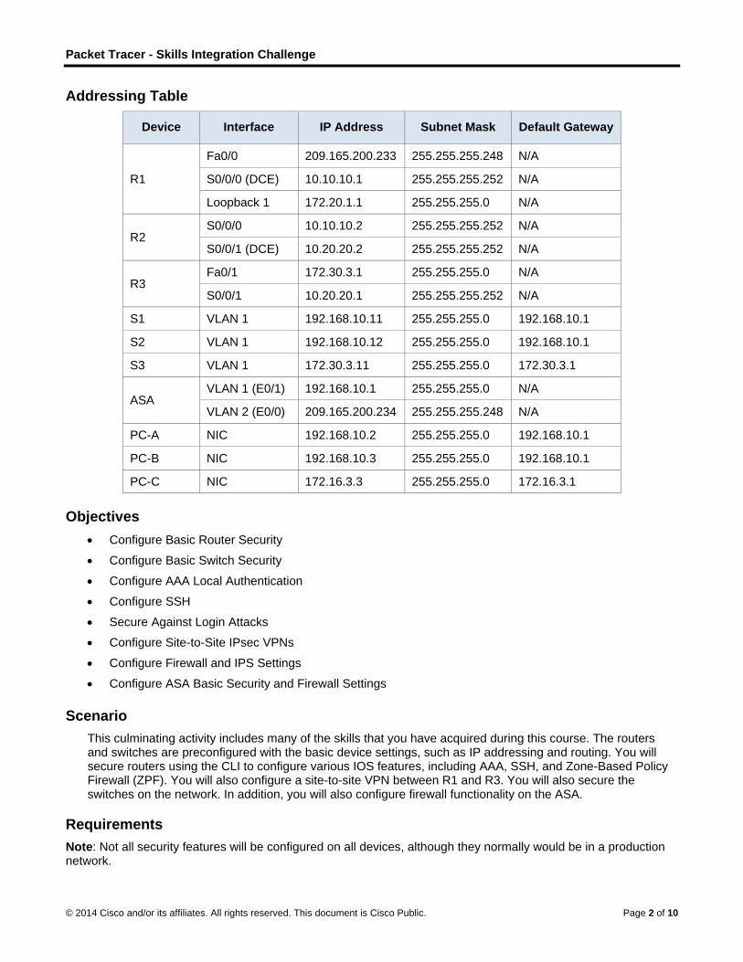
Packet Tracer - Skills Integration Challenge
© 2014 Cisco and/or its affiliates. All rights reserved. This document is Cisco Public. Page 2 of 10
Addressing Table
Device Interface IP Address Subnet Mask Default Gateway
R1
Fa0/0 209.165.200.233 255.255.255.248 N/A
S0/0/0 (DCE) 10.10.10.1 255.255.255.252 N/A
Loopback 1 172.20.1.1 255.255.255.0 N/A
R2 S0/0/0 10.10.10.2 255.255.255.252 N/A
S0/0/1 (DCE) 10.20.20.2 255.255.255.252 N/A
R3 Fa0/1 172.30.3.1 255.255.255.0 N/A
S0/0/1 10.20.20.1 255.255.255.252 N/A
S1 VLAN 1 192.168.10.11 255.255.255.0 192.168.10.1
S2 VLAN 1 192.168.10.12 255.255.255.0 192.168.10.1
S3 VLAN 1 172.30.3.11 255.255.255.0 172.30.3.1
ASA VLAN 1 (E0/1) 192.168.10.1 255.255.255.0 N/A
VLAN 2 (E0/0) 209.165.200.234 255.255.255.248 N/A
PC-A NIC 192.168.10.2 255.255.255.0 192.168.10.1
PC-B NIC 192.168.10.3 255.255.255.0 192.168.10.1
PC-C NIC 172.16.3.3 255.255.255.0 172.16.3.1
Objectives
Configure Basic Router Security
Configure Basic Switch Security
Configure AAA Local Authentication
Configure SSH
Secure Against Login Attacks
Configure Site-to-Site IPsec VPNs
Configure Firewall and IPS Settings
Configure ASA Basic Security and Firewall Settings
Scenario
This culminating activity includes many of the skills that you have acquired during this course. The routers and switches are preconfigured with the basic device settings, such as IP addressing and routing. You will secure routers using the CLI to configure various IOS features, including AAA, SSH, and Zone-Based Policy Firewall (ZPF). You will also configure a site-to-site VPN between R1 and R3. You will also secure the switches on the network. In addition, you will also configure firewall functionality on the ASA.
Requirements
Note: Not all security features will be configured on all devices, although they normally would be in a production network.
Packet Tracer - Skills Integration Challenge
© 2014 Cisco and/or its affiliates. All rights reserved. This document is Cisco Public. Page 3 of 10
Configure Basic Router Security
Configure the following on R1:
o Minimum password length is 10 characters.
o Encrypt plaintext passwords.
o Privileged EXEC mode secret password is ciscoenapa55.
o Console line password is ciscoconpa55, timeout is 15 minutes, and console messages should not
interrupt command entry.
o A message-of-the-day (MOTD) banner should include the word unauthorized.
Configure the following on R2:
o Privileged EXEC mode secret password is ciscoenapa55.
o Password for the vty lines is ciscovtypa55, timeout is 15 minutes, and login is required.
Configure Basic Switch Security
Configure the following on S1:
o Encrypt plaintext passwords.
o Privileged EXEC mode secret password is ciscoenapa55.
o Console line password is ciscoconpa55, timeout is 5 minutes, and consoles messages should not
interrupt command entry.
o Password for the vty lines is ciscovtypa55, timeout is 5 minutes, and login is required.
o A MOTD banner should include the word unauthorized.
Configure trunking between S1 and S2 with the following settings:
o Set the mode to trunk and assign VLAN 99 as the native VLAN.
o Disable the generation of DTP frames.
o Enable storm control for broadcasts to a 50 percent suppression level.
Configure the S1 with the following port settings:
o Fa0/6 should only allow access mode, set to PortFast, and enable BPDU guard.
o Fa0/6 uses basic default port security with dynamically learned MAC addresses added to the running
configuration.
o All other ports should be disabled.
Note: Although not all ports are checked, your instructor may want to verify that all unused ports are disabled.
Configure AAA Local Authentication
Configure the following on R1:
o Create a local user account of Admin01, a secret password of Admin01pa55, and a privilege level of
15.
o Enable AAA services.
o Implement AAA services using the local database as the first option and then the enable password
as the backup option.
Configure SSH
Configure the following on R1:
Note: The RSA key is already generated.
Packet Tracer - Skills Integration Challenge
© 2014 Cisco and/or its affiliates. All rights reserved. This document is Cisco Public. Page 4 of 10
o The domain name is ccnasecurity.com
o The RSA key should be generated with a 1024 modulus bits.
o Only SSH version 2 is allowed.
o Only SSH is allowed on vty lines.
Verify that PC-C can remotely access R1 (209.165.200.233) using SSH.
Secure Against Login Attacks
Configure the following on R1:
o If a user fails to log in twice within a 30-second time span, then disable logins for one minute.
o Log all failed login attempts.
Configure Site-to-Site IPsec VPNs
Note: Some VPN configurations are not scored. However, you should be able to verify connectivity across the IPsec VPN tunnel.
Instructor Note: Packet Tracer 6.1.0.0110 is crashes if any observables in the “IKE > Crypto Map Sets” branch are checked off and then the activity is tested.
Configure the following on R1:
o Create an access-list to identify interesting traffic on R1.
Configure ACL 101 to allow traffic from the R1 Lo1 network to the R3 Fa0/1 LAN.
Explicitly deny all other traffic.
o Configure the crypto isakmp policy 10 Phase 1 properties on R1 along with the shared crypto key
ciscovpnpa55. Use the following parameters:
Key distribution method: ISAKMP
Encryption: aes 256
Hash: sha-1
Authentication method: pre-shared
Key exchange: DH Group 5
IKE SA lifetime: 3600
ISAKMP key: ciscovpnpa55
o Create the transform set VPN-SET to use esp-aes 256 and esp-sha-hmac. Then create the crypto
map CMAP that binds all of the Phase 2 parameters together. Use sequence number 10 and identify
it as an ipsec-isakmp map. Use the following parameters:
Transform Set: VPN-SET
Transform Encryption: esp-aes 256
Transform Authentication: esp-sha-hmac
Perfect Forward Secrecy (PFS): group5
Crypto Map name: CMAP
SA Establishment: ipsec-isakmp
o Bind the crypto map CMAP to the outgoing interface.
Repeat the site-to-site VPN configurations on R3 so that they mirror all configurations from R1.
Ping the Lo1 interface (172.20.1.1) on R1 from PC-C. Then on R3, use the show crypto ipsec sa
command to verify the number of packets is more than 0, indicating that the IPsec VPN tunnel is working.
Configure Firewall and IPS Settings
Configure a ZPF on R3 using the following requirements:
Packet Tracer - Skills Integration Challenge
© 2014 Cisco and/or its affiliates. All rights reserved. This document is Cisco Public. Page 5 of 10
o Create zones named IN-ZONE and OUT-ZONE.
o Create an ACL number 110 that defines internal traffic, permitting all IP protocols from the
172.30.3.0/24 source network to any destination. Explicitly deny all other traffic.
o Create a class map named INTERNAL-CLASS-MAP that uses the match-all option and ACL 110.
o Create a policy map named IN-2-OUT-PMAP that uses the class map INTERNAL-CLASS-MAP to
inspect all matched traffic.
o Create a zone pair named IN-2-OUT-ZPAIR that identifies IN-ZONE as the source zone and OUT-
ZONE as the destination zone.
o Specify that the IN-2-OUT-PMAP policy map is to be used to inspect traffic between the two zones.
o Assign Fa0/1 as an IN-ZONE member and S0/0/1 as an OUT-ZONE member.
Configure an IPS on R3 using the following requirements:
Note: Within Packet Tracer, the routers already have the signature files imported and in place. They are the default XML files in flash. For this reason, it is not necessary to configure the public crypto key and complete a manual import of the signature files.
o Create a directory in flash named ipsdir and set it as the location for IPS signature storage.
o Create an IPS rule named IPS-RULE.
o Retire the all signature category with the retired true command (all signatures within the signature
release).
o Unretire the IOS_IPS Basic category with the retired false command.
o Apply the rule inbound on the S0/0/1 interface.
Configure ASA Basic Security and Firewall Settings
Configure VLAN interfaces with the following settings:
o For the VLAN 1 interface, configure the addressing to use 192.168.10.1/24.
o For the VLAN 2 interface, remove the default DHCP setting and configure the addressing to use
209.165.200.234/29.
Configure hostname, domain name, enable password, and Telnet console password using the following
settings:
o The ASA hostname is CCNAS-ASA.
o The domain name is ccnasecurity.com.
o The enable mode password is ciscoenapa55.
Create a user and configure AAA to use the local database for remote authentication.
o Create a local user account of Admin01 with a secret password of Admin01pa55 and a privilege
level of 15.
o Configure a local user account named admin with the password adminpa55. Do not use the
encrypted attribute.
o Configure AAA to use the local ASA database for Telnet and SSH user authentication.
Configure Telnet for local ASA console access and SSH for remote ASA console access.
o Allow Telnet access from the inside 192.168.10.0/24 network with a timeout of 10 minutes.
o Allow SSH access from the outside host 172.30.3.3 with a timeout of 10 minutes.
Configure the ASA as a DHCP server using the following settings:
o Assign IP addresses to inside DHCP clients from 192.168.10.5 to 192.168.10.30.
Packet Tracer - Skills Integration Challenge
© 2014 Cisco and/or its affiliates. All rights reserved. This document is Cisco Public. Page 6 of 10
o Enable DHCP to listen for DHCP client requests.
Configure static routing and NAT.
o Create a static default route to the next hop router (R1) IP address.
o Create a network object named inside-net and assign attributes to it using the subnet and nat
commands.
o Create a dynamic NAT translation to the outside interface.
Modify the Cisco Modular Policy Framework (MPF) on the ASA using the following settings:
o Configure class-map inspection_default to match default-inspection-traffic, and then exit to
global configuration mode.
o Configure the policy-map list, global_policy. Enter the class inspection_default and enter the
command to inspect icmp. Then exit to global config mode.
o Configure the MPF service-policy to make the global_policy apply globally.
Step-by-Step Scripts
!-------------------------------
!Configure Basic Router Security
!-------------------------------
!R1
conf t
security passwords min-length 10
enable secret ciscoenapa55
service password-encryption
line console 0
password ciscoconpa55
exec-timeout 15 0
login
logging synchronous
banner motd $Unauthorized access strictly prohibited and prosecuted to the full
extent of the law!$
end
!R2
conf t
enable secret ciscoenapa55
line vty 0 4
password ciscovtypa55
exec-timeout 15 0
login
end
!-------------------------
!Configure Switch Security
!-------------------------
!S1
conf t
service password-encryption
enable secret ciscoenapa55
Packet Tracer - Skills Integration Challenge
© 2014 Cisco and/or its affiliates. All rights reserved. This document is Cisco Public. Page 7 of 10
line console 0
password ciscoconpa55
exec-timeout 5 0
login
logging synchronous
line vty 0 4
password ciscovtypa55
exec-timeout 5 0
login
banner motd $Unauthorized access strictly prohibited and prosecuted to the full
extent of the law!$
end
!Trunking
!S1 and S2
conf t
interface FastEthernet 0/1
switchport mode trunk
switchport trunk native vlan 99
switchport nonegotiate
storm-control broadcast level 50
end
!S1 Port Security
conf t
interface FastEthernet 0/6
switchport mode access
spanning-tree portfast
spanning-tree bpduguard enable
shutdown
switchport port-security
switchport port-security mac-address sticky
no shutdown
interface range Fa0/2 – 5 , Fa0/7 – 24 , G0/1 - 2
shutdown
end
!----------------------------------
!Configure AAA Local Authentication
!----------------------------------
!R1
conf t
username Admin01 privilege 15 secret Admin01pa55
aaa new-model
aaa authentication login default local enable
end
!-------------------------
!Configure SSH
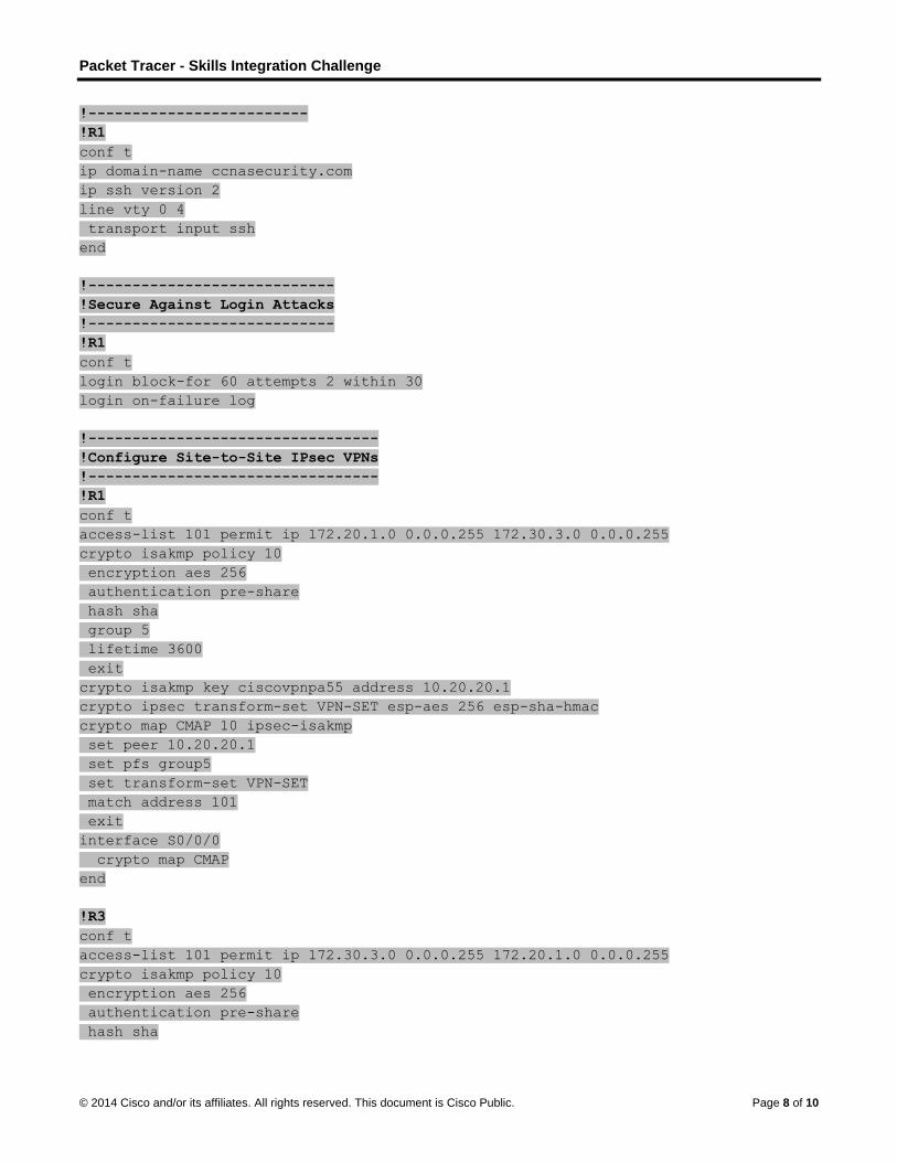
Packet Tracer - Skills Integration Challenge
© 2014 Cisco and/or its affiliates. All rights reserved. This document is Cisco Public. Page 8 of 10
!-------------------------
!R1
conf t
ip domain-name ccnasecurity.com
ip ssh version 2
line vty 0 4
transport input ssh
end
!----------------------------
!Secure Against Login Attacks
!----------------------------
!R1
conf t
login block-for 60 attempts 2 within 30
login on-failure log
!---------------------------------
!Configure Site-to-Site IPsec VPNs
!---------------------------------
!R1
conf t
access-list 101 permit ip 172.20.1.0 0.0.0.255 172.30.3.0 0.0.0.255
crypto isakmp policy 10
encryption aes 256
authentication pre-share
hash sha
group 5
lifetime 3600
exit
crypto isakmp key ciscovpnpa55 address 10.20.20.1
crypto ipsec transform-set VPN-SET esp-aes 256 esp-sha-hmac
crypto map CMAP 10 ipsec-isakmp
set peer 10.20.20.1
set pfs group5
set transform-set VPN-SET
match address 101
exit
interface S0/0/0
crypto map CMAP
end
!R3
conf t
access-list 101 permit ip 172.30.3.0 0.0.0.255 172.20.1.0 0.0.0.255
crypto isakmp policy 10
encryption aes 256
authentication pre-share
hash sha
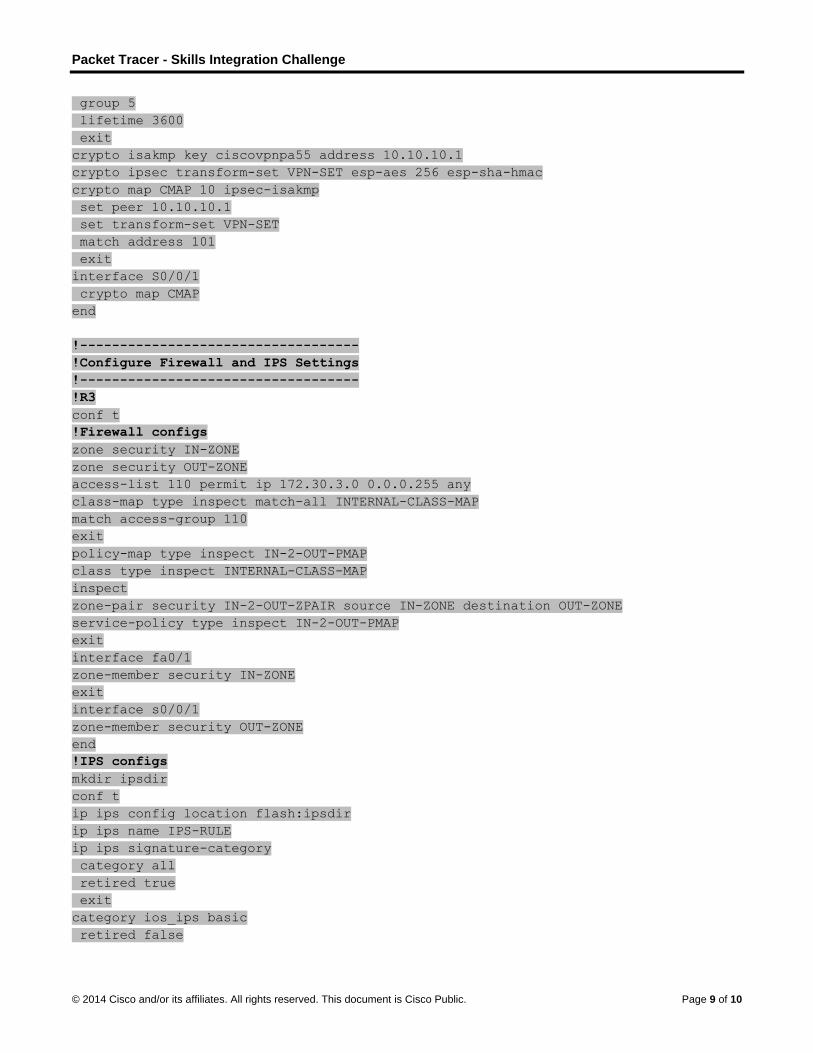
Packet Tracer - Skills Integration Challenge
© 2014 Cisco and/or its affiliates. All rights reserved. This document is Cisco Public. Page 9 of 10
group 5
lifetime 3600
exit
crypto isakmp key ciscovpnpa55 address 10.10.10.1
crypto ipsec transform-set VPN-SET esp-aes 256 esp-sha-hmac
crypto map CMAP 10 ipsec-isakmp
set peer 10.10.10.1
set transform-set VPN-SET
match address 101
exit
interface S0/0/1
crypto map CMAP
end
!-----------------------------------
!Configure Firewall and IPS Settings
!-----------------------------------
!R3
conf t
!Firewall configs
zone security IN-ZONE
zone security OUT-ZONE
access-list 110 permit ip 172.30.3.0 0.0.0.255 any
class-map type inspect match-all INTERNAL-CLASS-MAP
match access-group 110
exit
policy-map type inspect IN-2-OUT-PMAP
class type inspect INTERNAL-CLASS-MAP
inspect
zone-pair security IN-2-OUT-ZPAIR source IN-ZONE destination OUT-ZONE
service-policy type inspect IN-2-OUT-PMAP
exit
interface fa0/1
zone-member security IN-ZONE
exit
interface s0/0/1
zone-member security OUT-ZONE
end
!IPS configs
mkdir ipsdir
conf t
ip ips config location flash:ipsdir
ip ips name IPS-RULE
ip ips signature-category
category all
retired true
exit
category ios_ips basic
retired false
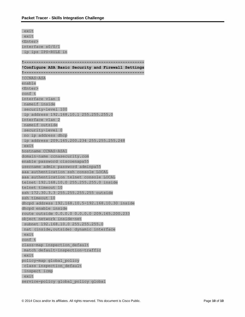
Packet Tracer - Skills Integration Challenge
© 2014 Cisco and/or its affiliates. All rights reserved. This document is Cisco Public. Page 10 of 10
exit
exit
<Enter>
interface s0/0/1
ip ips IPS-RULE in
!--------------------------------------------------
!Configure ASA Basic Security and Firewall Settings
!--------------------------------------------------
!CCNAS-ASA
enable
<Enter>
conf t
interface vlan 1
nameif inside
security-level 100
ip address 192.168.10.1 255.255.255.0
interface vlan 2
nameif outside
security-level 0
no ip address dhcp
ip address 209.165.200.234 255.255.255.248
exit
hostname CCNAS-ASA1
domain-name ccnasecurity.com
enable password ciscoenapa55
username admin password adminpa55
aaa authentication ssh console LOCAL
aaa authentication telnet console LOCAL
telnet 192.168.10.0 255.255.255.0 inside
telnet timeout 10
ssh 172.30.3.3 255.255.255.255 outside
ssh timeout 10
dhcpd address 192.168.10.5-192.168.10.30 inside
dhcpd enable inside
route outside 0.0.0.0 0.0.0.0 209.165.200.233
object network inside-net
subnet 192.168.10.0 255.255.255.0
nat (inside,outside) dynamic interface
exit
conf t
class-map inspection_default
match default-inspection-traffic
exit
policy-map global_policy
class inspection_default
inspect icmp
exit
service-policy global_policy global