Embed Size (px)
Citation preview
The Essential Differences Between Commercial & Industrial UPS Systems Page 1 of 8
version14b - Page 1
Working definitions of terms: Commercial vs. Industrial UPS Systems:
On-Line, Uninterruptible Power Systems (abbreviated: UPS) have been available for almost 40 years.The UPS market for On-line UPS covering capacities between: 5 – 150 kVA is still growing at 12%annual rate as Business and Industry become more dependent on the continuous flow of digital data.
According to Frost & Sullivan, almost 8 out of 10 UPS systems (>80%) produced now are designedfor Information Technology applications. It is not surprising that Industrial UPS specifiers have a diffi-cult time identifying the critical differences between Commercial and Industrial UPS equipment.In general, the application universe for On-Line UPS systems can be broken into three (3) broadsegments:
(1.) Information Technology (formerly called Electronic Data Processing) - The term Com-mercial UPS has become associated with Information Technology (IT) because the UPS andcomputer room are often purchased as a package from construction contractors. The bid-ding specifications for IT UPS equipment are not technically demanding and typically requireonly safety certification to UL or CSA. The Data Centers in banks, hospitals and insurancecompanies are examples of typical IT UPS applications. The interruption of AC power maydisrupt data processing and telecommunications, but does not create an inherent risk of in-jury to people or property.
(Note: There are specific UL safety standards for safety-related UPS such as emergencylighting UPS or medical diagnostic equipment, but the UL standards are primarily safety fo-cused and do not address UPS performance testing or designing for reliability.)
(2.) Critical Process Control - Over the years, UPS systems designed for Critical ProcessControl applications have earned the name: Industrial UPS. In these types of applications,the interruption of AC power may cause dangerous chemical process instability, or causeexpensive damage to the processing systems. Petrochemical Complexes and ElectricalPower Generation Plants are good examples of operations that use chemical or steam proc-esses that can become dangerous if control power is interrupted. Because of the risk re-sulting from the loss of control power, UPS systems intended for Industrial applications mustbe designed and performance tested to a more rigorous level than commercial equipment.
(3.) General Process Control - There are applications that fall into a middle ground that wewill label as Light Industrial. These types of applications have processes that are not inher-ently dangerous, even if AC power is interrupted during process operation. However, inthese processes, the failure of the UPS to supply continuous AC power may result in loss offinished products or in hundreds of man-hours resetting the production equipment. Pharma-ceuticals and the Food & Beverage Industries would be examples of Light Industrial classifi-cations.

The Essential Differences Between Commercial & Industrial UPS Systems Page 2 of 8
version14b - Page 2
Some of the major application-driven differences between the IT UPS (Commercial) and ProcessControl UPS (Industrial) are summarized in Table 1:
Evaluation Factors IT – Commercial UPS Industrial UPS
A Electrical – Surge Levels & EMI/RFI
a1 On the AC Mains to Rectifier/Charger Low Levels in IT Data Centers Surge & EMI/RFI Levels can be higha2 On the UPS Static Bypass Input Low Levels in IT Data Centers Surge & EMI/RFI Levels can be higha3 On the DC Input - Battery Dedicated Inverter Battery,
no external connectionPower Gen. UPS often connected toStation Battery High DC Transients
a4 Input Isolation Transformer Not usually specified for IT use Usually Specified in Industrial setting
B Physical Environment – UPS Area
b1 Ambient temperature range 25 – 35 Degrees Celsius 15 – 55 Degrees Celsiusb2 Air Humidity 10 – 55 % RH 10 – 95 % RHb3 Air Contaminants Very Low Levels found in
Office Buildings & Data CentersOften very dusty, sometimes corrosive air contaminants also
C UPS Static Switch Design
c1 Full Electronic vs. Hybrid Configuration Hybrid - electromechanical Full Electronic – SCR devices inboth Inverter & Bypass poles
c2 Sustained Load Fault Clearing on By-pass
Damage to static switch underfault at critical load
SCR devices are sized for worst-case bypass fault current.
D UPS Failure Contingency
d1 Static Switch Power Supply failure May drop critical loads Static Switch Fails to Bypass Sourced2 Control Microprocessor Failure May drop critical loads Static Switch Fails to Bypass Sourced3 Spare parts & Obsolescence generally – 5 to 7 yr. Product Life 15 –25 yr. support required
E Manual Bypass Scheme
e1 Drum Switch vs. Circuit Breaker Circuit Breaker Only Drum Switch – zero breake2 Independence from Static Switch Needs Static Switch for zero-
break transferIndependent of Static switch
F UPS Battery
f1 Design Life VRLA – 5 years VRLA & Flooded – 20 yearsf2 Support time Range 15 – 30 minutes 60 – 480 minutesf3 Depth of Discharge / End Voltage 90% - 1.65 volts per cell 60 -80%, minimum 1.75 vpc
Battery Re-charge Time to 90%of Original Capacity
Not usually specified, becausebattery time is less than 1 hour
Battery Chargers are sized toachieve 8 hour recharge
G 100 % Performance Testing Not usually required. Typetest data submittal accepted
Certified Test Data per NEMA PE-1,NEMA PE-5, IEE-944, IEC-146
H Equipment Design Life 5 – 7 Years in IT Data Centers 10 - 15 Years in Petrochemical15 – 30 Years in Power Gen.
I Inverter Technologies PWM Inverters Dominate Split between Ferroresonant andPWM Inverters

The Essential Differences Between Commercial & Industrial UPS Systems Page 3 of 8
version14b - Page 3
EMI/RFI & Electrical Surge Levels – IT Applications vs. Industrial:
A typical IT Data Center is represented above in Fig. 1. We can see from the diagram that IT DataCenters are EMI/RFI-Surge protected environments. The IEEE Orange & Emerald Books recom-mend not only Lightning Arrestors, but also Delta-Wye transformer isolation on the UPS mains. Thedesign of the Data Center’s AC power distribution system protects the UPS from the effects of in-coming EMI/RFI (electromagnetic & radio frequency interference) on the AC Mains and Bypass Inputfeeders.
The use of dedicated input power feeders, with the isolation transformers, not only reduces EMI/RFI,but also reduces the available fault current at the UPS AC mains. Competitive pricing pressure andthe protected IT electrical environment sometimes justify the omission of the input isolation trans-former in the rectifier section. The Specifying Engineer should carefully evaluate the UPS electricalenvironment, particularly in an industrial application, to make sure that a rectifier input isolation trans-former is not required.
Fig. 2 below shows the Industrial UPS rectifier section with an input isolation transformer. In someIndustrial applications, the UPS AC input power is fed from Switchgear or Motor Control Centers(MCC) and often shares bus connections with electrically noisy loads such as variable speed drives.An input isolation transformer may be necessary the Industrial UPS environment to protect the UPSfrom the effects of power feeder surges and RFI/EMI.
Fig. 2 - UPS with an Rectifier Section Isolation Transformer
The Essential Differences Between Commercial & Industrial UPS Systems Page 4 of 8
version14b - Page 4
UPS Environmental Considerations are often driven by the Application:
Many Industrial UPS environments, particularly those in Power Generation applications, have higherambient temperatures, (i.e. > 30OC.) and particulate contamination of the air. Industrial UPS equip-ment is designed to tolerate moderate amounts of non-conductive dust and high ambient air tem-peratures of at least 40 C. and usually has an optional design for 50OC. ambient temperature.
Geothermal Power plants often produce as a process byproduct sulfur dioxide gas. Sulfur dioxide gasforms dilute sulfuric acid when combined with moist air. Industrial UPS systems designed for Geo-thermal Power applications will have epoxy-coated or nickel-plated copper bus bar, special anti-corrosion terminal connections, and acid resistant metal surface coatings. In extreme cases, thecooling air to the UPS cabinets is brought in from a clean (or scrubbed) source at a positive pressureand exhausted out of the cabinet tops to keep atmospheric pollutants out of the UPS interior spaces.
In contrast, the IT UPS environment is almost always temperature controlled at 30OC. and kept veryclean. The service life of any UPS system is reduced by operation in high ambient temperatures.The critical UPS component most affected by high ambient temperatures is the UPS battery, but otherinternal UPS components, such as DC bus filtering capacitors, may have their service life shortenedby high ambient temperatures unless special high-temp capacitors are selected.
In the IT UPS applications, the UPS Specifier may not require long UPS service life, but in critical pro-cess control, a UPS service life of 15-20 years is often specified. Industrial UPS systems have built-indesign margins to preserve the operation life in less than perfect environments. In addition, IndustrialUPS equipment will also have predictive parts replacement programs to insure high UPS MTBF overthe entire 15-20 year service life.
UPS Static Switch Designs – Hybrid vs. Full Electronic Static Switch Types:
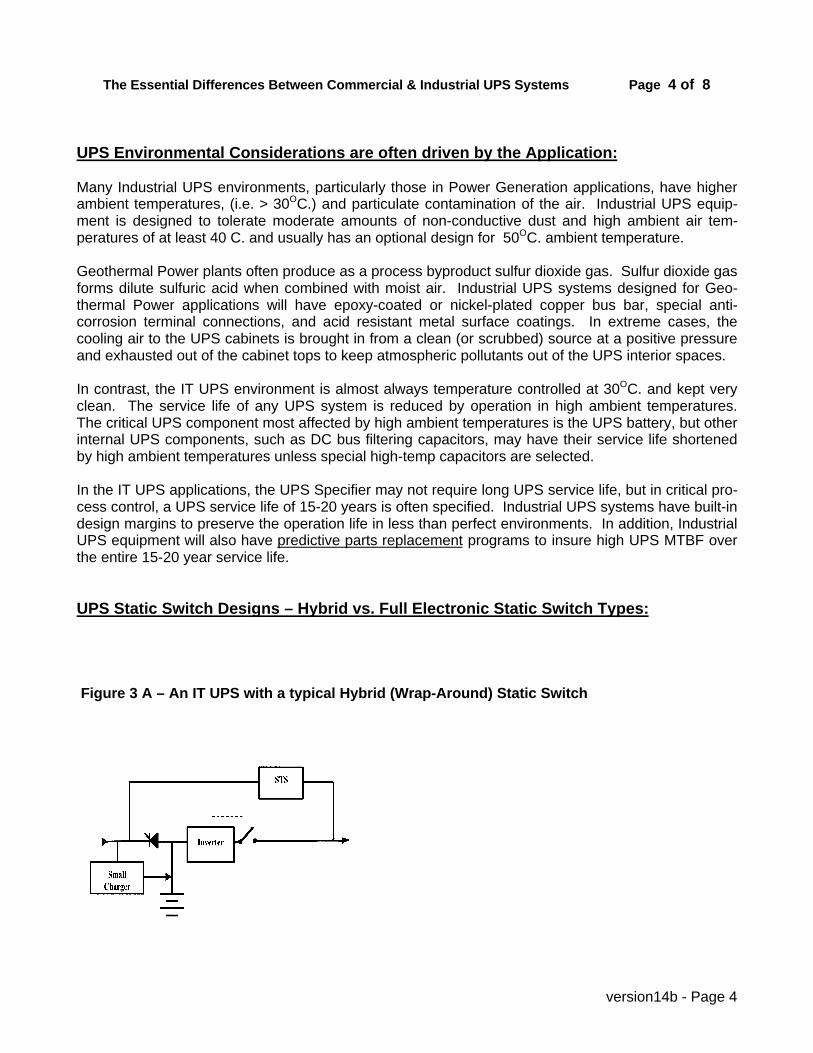
Figure 3 A – An IT UPS with a typical Hybrid (Wrap-Around) Static Switch
The Essential Differences Between Commercial & Industrial UPS Systems Page 5 of 8
version14b - Page 5
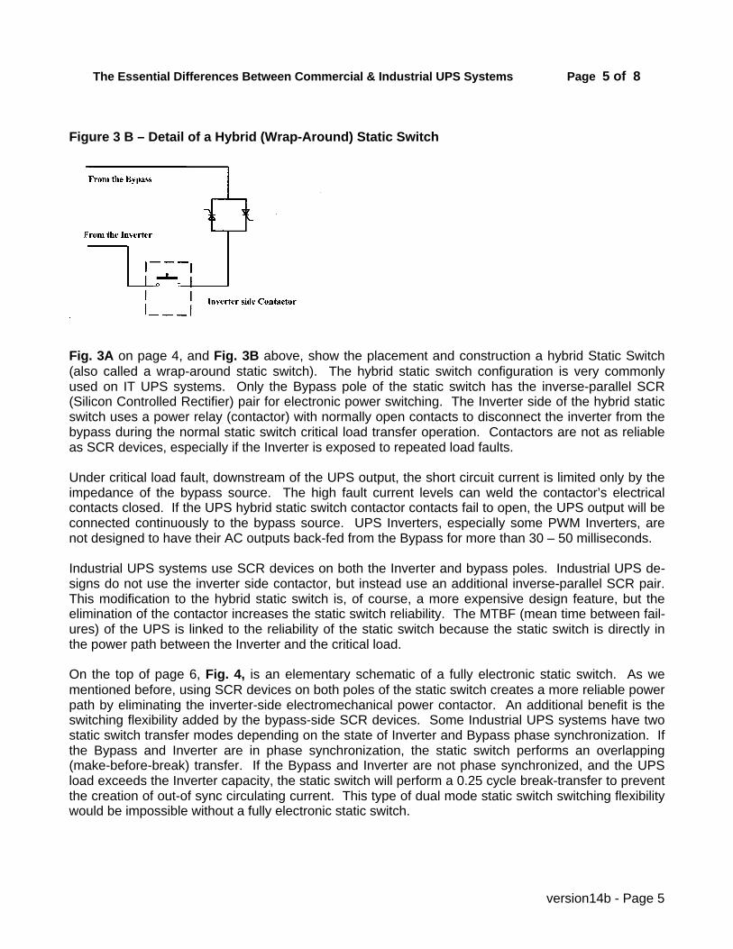
Figure 3 B – Detail of a Hybrid (Wrap-Around) Static Switch
Fig. 3A on page 4, and Fig. 3B above, show the placement and construction a hybrid Static Switch(also called a wrap-around static switch). The hybrid static switch configuration is very commonlyused on IT UPS systems. Only the Bypass pole of the static switch has the inverse-parallel SCR(Silicon Controlled Rectifier) pair for electronic power switching. The Inverter side of the hybrid staticswitch uses a power relay (contactor) with normally open contacts to disconnect the inverter from thebypass during the normal static switch critical load transfer operation. Contactors are not as reliableas SCR devices, especially if the Inverter is exposed to repeated load faults.
Under critical load fault, downstream of the UPS output, the short circuit current is limited only by theimpedance of the bypass source. The high fault current levels can weld the contactor’s electricalcontacts closed. If the UPS hybrid static switch contactor contacts fail to open, the UPS output will beconnected continuously to the bypass source. UPS Inverters, especially some PWM Inverters, arenot designed to have their AC outputs back-fed from the Bypass for more than 30 – 50 milliseconds.
Industrial UPS systems use SCR devices on both the Inverter and bypass poles. Industrial UPS de-signs do not use the inverter side contactor, but instead use an additional inverse-parallel SCR pair.This modification to the hybrid static switch is, of course, a more expensive design feature, but theelimination of the contactor increases the static switch reliability. The MTBF (mean time between fail-ures) of the UPS is linked to the reliability of the static switch because the static switch is directly inthe power path between the Inverter and the critical load.
On the top of page 6, Fig. 4, is an elementary schematic of a fully electronic static switch. As wementioned before, using SCR devices on both poles of the static switch creates a more reliable powerpath by eliminating the inverter-side electromechanical power contactor. An additional benefit is theswitching flexibility added by the bypass-side SCR devices. Some Industrial UPS systems have twostatic switch transfer modes depending on the state of Inverter and Bypass phase synchronization. Ifthe Bypass and Inverter are in phase synchronization, the static switch performs an overlapping(make-before-break) transfer. If the Bypass and Inverter are not phase synchronized, and the UPSload exceeds the Inverter capacity, the static switch will perform a 0.25 cycle break-transfer to preventthe creation of out-of sync circulating current. This type of dual mode static switch switching flexibilitywould be impossible without a fully electronic static switch.

The Essential Differences Between Commercial & Industrial UPS Systems Page 6 of 8
version14b - Page 6
Figure 4 – Fully Electronic, Industrial Static Switch
UPS Contingency Design Analysis:
Contingency Design analysis is the examination of how the UPS behaves when the unexpected hap-pens? For example: Suppose the internal power supply to the static switch control board fails. Is thestatic switch fail safe? Specifically, will the static switch transfer smoothly to the bypass source upona static switch control board power supply failure? In many IT UPS systems, the answer is: No! If thepower supply fails, the static switch, if it is not a true fail-safe design, can not transfer the critical UPSload because the SCR gate drive no longer has the power necessary to operate correctly.
Few IT UPS systems use fail-safe static switch designs. Very commonly the SCR gating circuits inthe hybrid static switch are triggered by opto-couplers which require external power to develop theSCR gate trigger pulses.
In a fail-safe static switch design, the static switch SCR devices derive their gating power from theload current. SCR gate drive reed relays with magnetic bias are set up so that the Bypass side SCRdevices are gated on by the normally closed reed relay contacts. In a fail-safe static switch, a powersupply failure will force the UPS to transfer the critical load from the Inverter to the Bypass.
The Essential Differences Between Commercial & Industrial UPS Systems Page 7 of 8
version14b - Page 7
It is common these days for UPS equipment to use microprocessor control. Unfortunately, unlesscareful thought is given as to how to limit the scope of microprocessor control, single point failuremode creates a problem if the microprocessor fails. In UPS designs that have not considered singlepoint failure modes, the failure of the microprocessor results not only in the sudden loss of UPS out-put, but also the failure of the static switch to transfer of the critical load to the bypass.
In an Industrial UPS design, single point failure modes are carefully considered and eliminated if at allpossible. In a well designed, microprocessor-controlled UPS, both internal and external watchdog cir-cuits monitor the microprocessor’s calculations continuously. If a microprocessor error is detected,the Industrial UPS, with its independent and fail-safe static switch, immediately transfers the criticalUPS load to the Bypass.
The Manual Bypass Switch (MBS) gives the maintenance personnel the ability to place the criticalUPS load on the Bypass source intentionally for UPS service. In an IT UPS, the manual bypass func-tion is usually performed with a circuit breaker. The load to bypass transfer is first accomplished viathe static switch and then sealed or jumpered by closing the manual bypass breaker. While thisseems like a simple bypass method, it depends entirely on the proper operation of the UPS staticswitch. If the static switch is not operational, the manual bypass operation via the manual bypassbreaker will not work as intended.
The Industrial UPS uses a make-before-break rotary drum switch. The manual bypass switching iscompletely independent of the static switch operation. In some Industrial UPS designs, the manualbypass switch has additional power switching contacts that isolate the static switch from the Bypassand Inverter to facilitate maintenance access.
UPS Batteries & Chargers:
In general, IT UPS applications specify valve-regulated, lead-acid batteries in the 10 – 30 minuteranges. Because the IT UPS Battery support times are usually not as long as those used in Industrialapplications, charger capacity is usually not given much attention. The UPS battery chargers in the ITmarketplace are typically sized to re-charge a 15 -30 minute lead-acid UPS battery to 95% capacity in8-10 hours.
In contrast, in Industrial applications, the charger capacity often has to be much larger because thebattery support times can range from 60 minutes to 8 hours or more. The UPS specifier needs tocheck to make sure the UPS system being considered has enough battery re-charge capacity builtinto the Charger, especially in Industrial applications like Power generation that typically use 4-8 hourUPS Batteries.
It is common in IT UPS applications to discharge the lead-acid UPS Batteries more deeply, usually tothe end of discharge voltage of 1.65 volts per cell. In contrast, Industrial UPS systems will use ahigher end voltage of 1.75 volts per cell. Discharging the UPS Batteries to a lower end voltage willremove more energy from the cells and result in a smaller UPS battery. Keep in mind that deeper celldischarge reduces the service life of the UPS batteries. Lead-acid cells, especially the less expensive5-10 year service life cells, are very sensitive to depth of discharge. The UPS specifier needs tocarefully weigh the consequences of reduced battery service life when lead-acid UPS batteries aredischarged below 1.75 vpc.

The Essential Differences Between Commercial & Industrial UPS Systems Page 8 of 8
version14b - Page 8
Equipment Design Life – matching UPS service life to the critical process service life:
Industrial UPS equipment will have design margins built into its components so that the UPS systemwill have >100,000 hours of MTBF when operated in typical Industrial environments. There are com-ponents like cooling fans and DC capacitors that degrade with time, even with conservative designpractices. Industrial UPS users such as Power Generation plants commonly specify UPS servicelives in the 20 – 30 year life spans. Petrochemical UPS specifiers have a shorter time horizon usuallyin the 10 –15 year range, but, in general, the Industrial UPS specifier is looking for a longer UPSservice life because the process drives the decision.
Industrial UPS suppliers will have documented component replacement schedules – components likecooling fans and DC capacitors – so that the UPS MTBF can be maintained over the 20-30 yearservice life. True Industrial UPS suppliers will have spare parts replacement programs that supportolder UPS equipment in the field. Industrial UPS suppliers, because they have to support their olderUPS equipment, will have field data available to support their UPS MTBF figures in their data sheets.
Industrial UPS suppliers will keep UPS models around for longer intervals and tend to avoid productobsolescence because they are geared to support the older UPS systems in the field. Backwardcompatibility of UPS components is always an important design issue with an Industrial UPS supplier.
In the Commercial UPS marketplace, UPS models tend to become obsolete in 5 years. Today, thelongevity of a typical Data Center -driven mostly by data technology change - is less than 5 years. ITUPS suppliers who know their marketplace very well, tend to concentrate their design efforts on mak-ing next year’s model cheaper, smaller, and more efficient. Rapid IT UPS product obsolescencemakes long term support of older UPS equipment in the field very difficult.
The Industrial UPS specifier should be aware of the long-term support issues when selecting a sup-plier. When one considers the life-cycle costs of a UPS, especially in large process applications,an Industrial UPS design, with a scheduled critical parts replacement program, is a much lower costsolution that UPS replacement.
Inverter Technologies – Ferroresonant & PWM
Ferroresonant Inverters have been used in Industrial applications for almost 40 years. These Invert-ers are still preferred for the really demanding UPS applications (such as in nuclear power) becauseof their power circuit simplicity and inherent fail-safe design. Please refer to the Solidstate Controlsapplication paper: Sizing a UPS System for Non-Linear Loads for more information about Ferro-resonant & PWM Inverter technologies.
PWM (Pulse-Width-Modulated) Inverters have become more acceptable to Industrial UPS Specifiersover the last decade due to improvements in the reliability and switching speed of the IGBT powertransistors. Please note that regardless of the Inverter technology selected, Industrial UPS equipmentwill always be more expensive than Commercial UPS equipment because their applications, as wehave explored in this paper, are very different.