Embed Size (px)
Citation preview

EXPERIMENT N o. 1
EXPERIMENT NO. 01
Name of Experiment : Generation of Line using DDA and Bresnham’s Principle (Derivation, Algorithm, Flow Chart, C-
Programme and its Output)
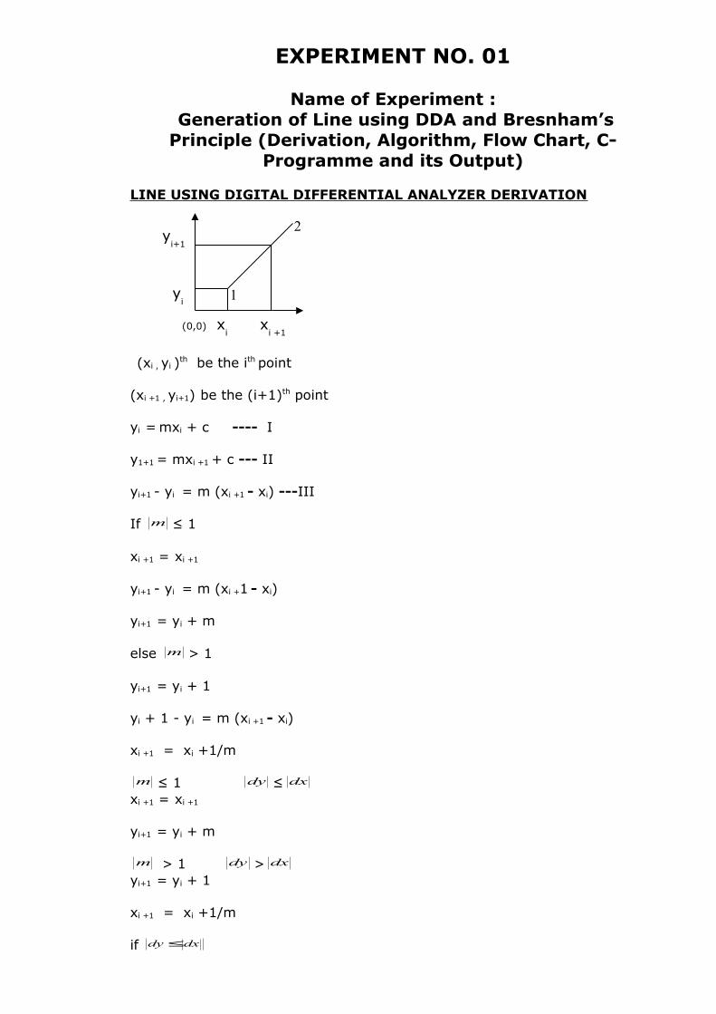
LINE USING DIGITAL DIFFERENTIAL ANALYZER DERIVATION
(xi , yi )th be the ith point
(xi +1 , yi+1) be the (i+1)th point
yi = mxi + c ---- I
y1+1 = mxi +1 + c --- II
yi+1 - yi = m (xi +1 - xi) ---III
If m ≤ 1
xi +1 = xi +1
yi+1 - yi = m (xi +1 - xi)
yi+1 = yi + m
else m > 1
yi+1 = yi + 1
yi + 1 - yi = m (xi +1 - xi)
xi +1 = xi +1/m
m ≤ 1 dy ≤ dxxi +1 = xi +1
yi+1 = yi + m
m > 1 dy > dxyi+1 = yi + 1
xi +1 = xi +1/m
if dxdy≤
(0,0) xi
xi +1
yi+1
yi 1
2
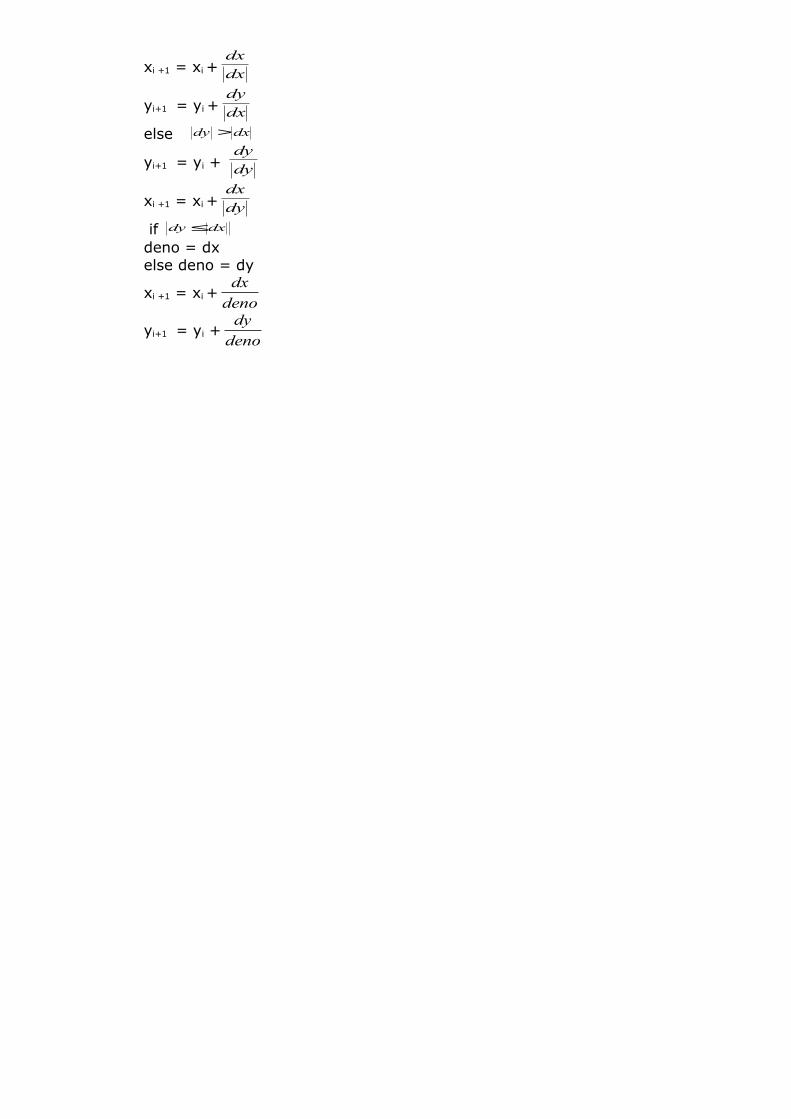
xi +1 = xi + dxdx
yi+1 = yi + dxdy
else dxdy >
yi+1 = yi + dydy
xi +1 = xi + dydx
if dxdy≤
deno = dxelse deno = dy
xi +1 = xi +deno
dx
yi+1 = yi +deno
dy
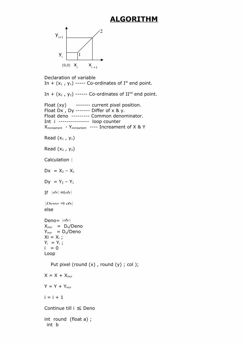
ALGORITHM
Declaration of variableIn + (x1 , y1) ----- Co-ordinates of Ist end point.
In + (x2 , y2) ------ Co-ordinates of IInd end point.
Float (xy) ------- current pixel position.Float Dx , Dy ------- Differ of x & y.Float deno --------- Common denominator.Int i --------------- loop counterXincreament - Yincreament ---- Increament of X & Y
Read (x1 , y1)
Read (x2 , y2)
Calculation :
Dx = X2 – X1
Dy = Y2 – Y1
If dydx ≤
=Deno dx
else Deno= dyXincr = Dx/DenoYincr = Dy/DenoXi = Xi ;Yi = Yi ;i = 0Loop Put pixel (round (x) , round (y) ; col );
X = X + Xincr
Y = Y + Yincr
i = i + 1
Continue till i ≤ Deno
int round (float a) ;int b
(0,0) xi
xi +1
yi+1
yi 1
2
b = a+ 0.5 ;return b ;
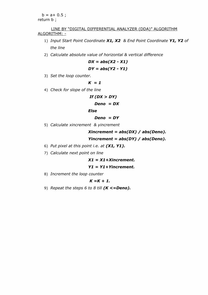
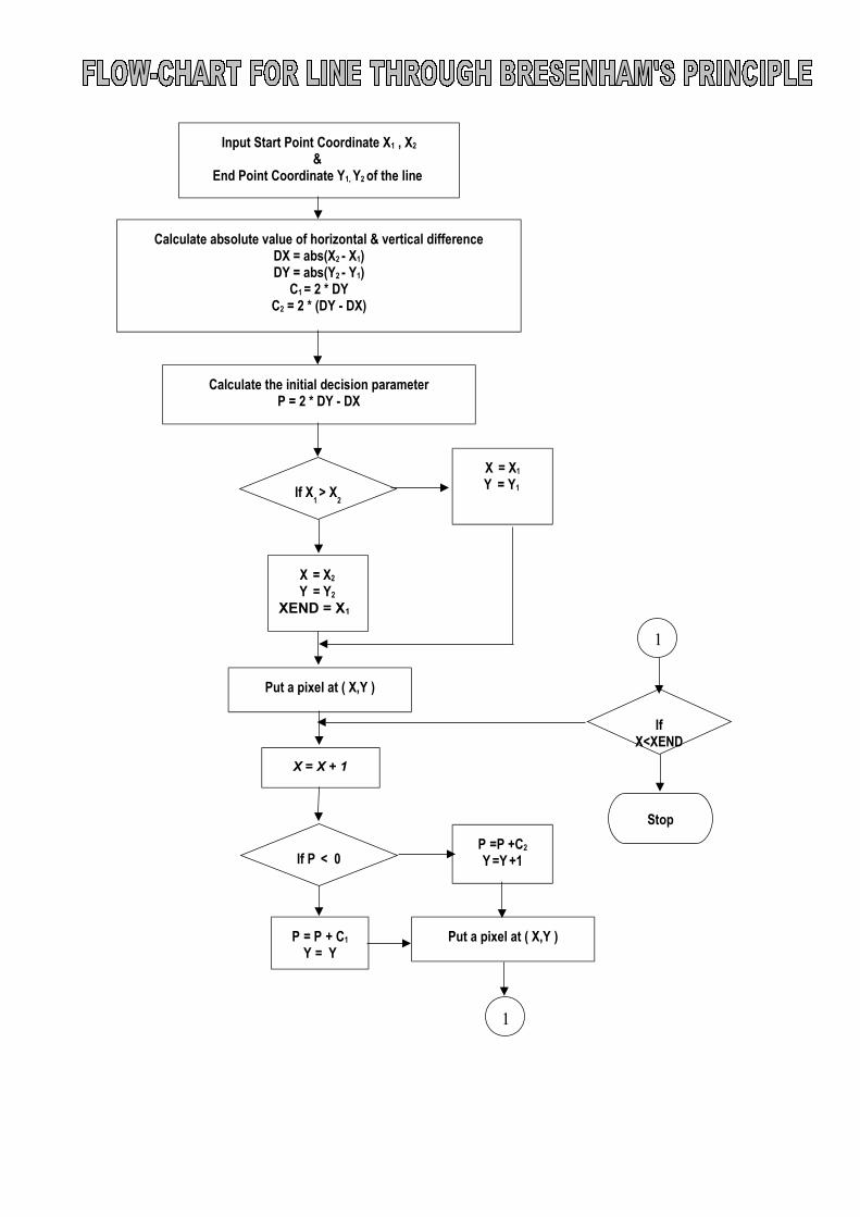
LINE BY “DIGITAL DIFFERENTIAL ANALYZER (DDA)” ALGORITHMALGORITHM: -
1) Input Start Point Coordinate X1, X2 & End Point Coordinate Y1, Y2 of
the line
2) Calculate absolute value of horizontal & vertical difference
DX = abs(X2 - X1)
DY = abs(Y2 - Y1)
3) Set the loop counter.
K = 1
4) Check for slope of the line
If (DX > DY)
Deno = DX
Else
Deno = DY
5) Calculate xincrement & yincrement
Xincrement = abs(DX) / abs(Deno).
Yincrement = abs(DY) / abs(Deno).
6) Put pixel at this point i.e. at (X1, Y1).
7) Calculate next point on line
X1 = X1+Xincrement.
Y1 = Y1+Yincrement.
8) Increment the loop counter
K =K + 1.
9) Repeat the steps 6 to 8 till (K <=Deno).
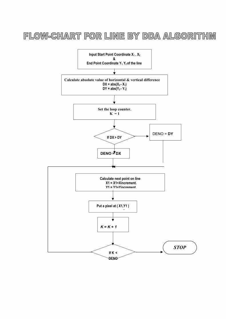
Calculate absolute value of horizontal & vertical differenceDX = abs(X2 - X1)DY = abs(Y2 - Y1)
Set the loop counter.K = 1
K = K + 1
If K <
DENO
Put a pixel at ( X1,Y1 )
Input Start Point Coordinate X1 , X2
& End Point Coordinate Y1, Y2 of the line
If DX > DY
DENO = DX
DENO = DY
Calculate next point on lineX1 = X1+Xincrement.Y1 = Y1+Yincrement.
STOP
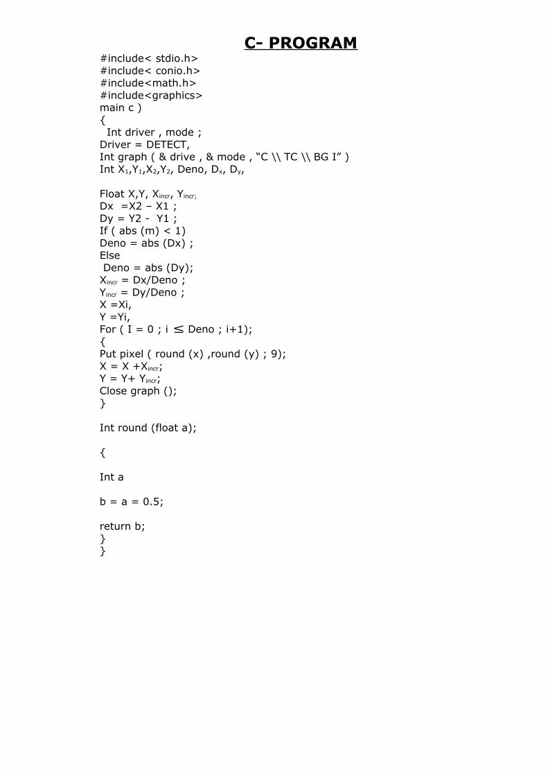
C- PROGRAM#include< stdio.h>#include< conio.h>#include<math.h>#include<graphics>main c ){ Int driver , mode ;Driver = DETECT,Int graph ( & drive , & mode , “C \\ TC \\ BG I” )Int X1,Y1,X2,Y2, Deno, Dx, Dy,
Float X,Y, Xincr, Yincr;
Dx =X2 – X1 ;Dy = Y2 - Y1 ;If ( abs (m) < 1)Deno = abs (Dx) ;Else Deno = abs (Dy);Xincr = Dx/Deno ;Yincr = Dy/Deno ;X =Xi,Y =Yi,For ( I = 0 ; i ≤ Deno ; i+1);{Put pixel ( round (x) ,round (y) ; 9);X = X +Xincr;Y = Y+ Yincr;Close graph ();}
Int round (float a);
{ Int a b = a = 0.5;
return b;}}
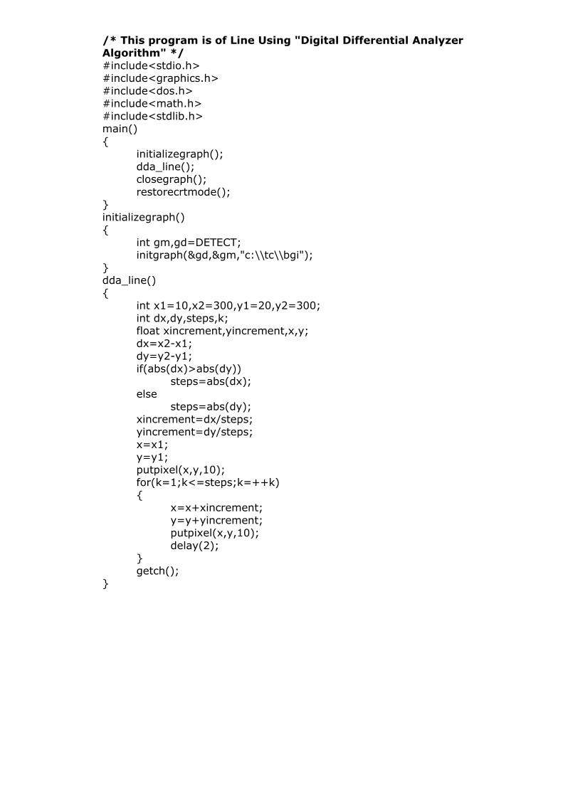
/* This program is of Line Using "Digital Differential Analyzer Algorithm" */#include<stdio.h>#include<graphics.h>#include<dos.h>#include<math.h>#include<stdlib.h>main(){
initializegraph();dda_line();closegraph();restorecrtmode();
}initializegraph(){
int gm,gd=DETECT;initgraph(&gd,&gm,"c:\\tc\\bgi");
}dda_line(){
int x1=10,x2=300,y1=20,y2=300;int dx,dy,steps,k;float xincrement,yincrement,x,y;dx=x2-x1;dy=y2-y1;if(abs(dx)>abs(dy))
steps=abs(dx);else
steps=abs(dy);xincrement=dx/steps;yincrement=dy/steps;x=x1;y=y1;putpixel(x,y,10);for(k=1;k<=steps;k=++k){
x=x+xincrement;y=y+yincrement;putpixel(x,y,10);delay(2);
}getch();
}
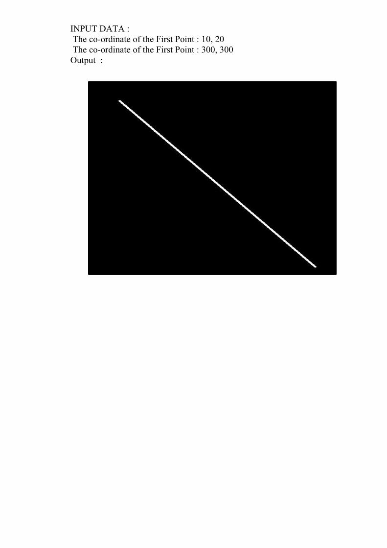
INPUT DATA : The co-ordinate of the First Point : 10, 20 The co-ordinate of the First Point : 300, 300Output :
Generation of Line using Bresenham’s Principle (Derivation, Algorithm, Flow Chart, C-Programme and its
Output)
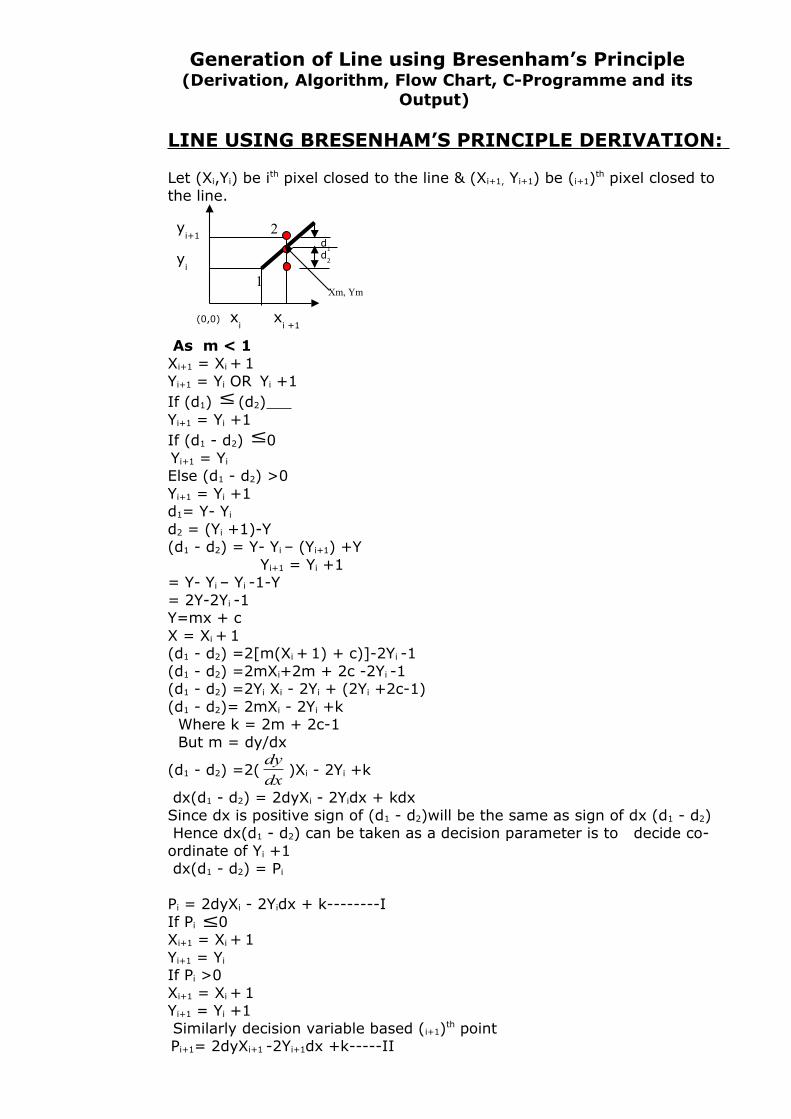
LINE USING BRESENHAM’S PRINCIPLE DERIVATION:
Let (Xi,Yi) be ith pixel closed to the line & (Xi+1, Yi+1) be (i+1)th pixel closed to the line.
As m < 1 Xi+1 = Xi + 1Yi+1 = Yi OR Yi +1If (d1) ≤ (d2) Yi+1 = Yi +1If (d1 - d2) ≤0 Yi+1 = Yi
Else (d1 - d2) >0Yi+1 = Yi +1d1= Y- Yi
d2 = (Yi +1)-Y(d1 - d2) = Y- Yi – (Yi+1) +Y Yi+1 = Yi +1= Y- Yi – Yi -1-Y= 2Y-2Yi -1Y=mx + cX = Xi + 1(d1 - d2) =2[m(Xi + 1) + c)]-2Yi -1(d1 - d2) =2mXi+2m + 2c -2Yi -1(d1 - d2) =2Yi Xi - 2Yi + (2Yi +2c-1)(d1 - d2)= 2mXi - 2Yi +k Where k = 2m + 2c-1 But m = dy/dx
(d1 - d2) =2(dx
dy)Xi - 2Yi +k
dx(d1 - d2) = 2dyXi - 2Yidx + kdxSince dx is positive sign of (d1 - d2)will be the same as sign of dx (d1 - d2) Hence dx(d1 - d2) can be taken as a decision parameter is to decide co-ordinate of Yi +1 dx(d1 - d2) = Pi
Pi = 2dyXi - 2Yidx + k--------IIf Pi ≤0Xi+1 = Xi + 1Yi+1 = Yi
If Pi >0Xi+1 = Xi + 1Yi+1 = Yi +1 Similarly decision variable based (i+1)th point Pi+1= 2dyXi+1 -2Yi+1dx +k-----II
(0,0) xi
xi +1
yi+1
yi
1
2d
1d
2
Xm, Ym
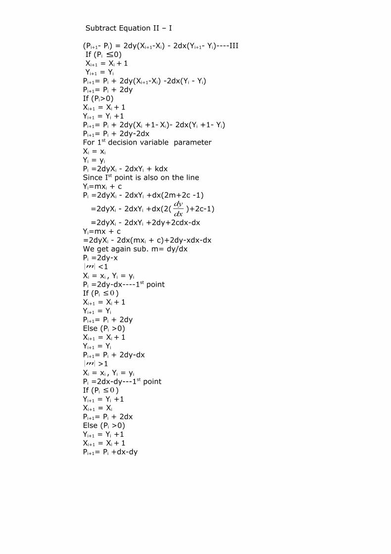
Subtract Equation II – I
(Pi+1- Pi) = 2dy(Xi+1-Xi) - 2dx(Yi+1- Yi)----III If (Pi ≤0) Xi+1 = Xi + 1 Yi+1 = Yi
Pi+1= Pi + 2dy(Xi+1-Xi) -2dx(Yi - Yi) Pi+1= Pi + 2dyIf (Pi>0)Xi+1 = Xi + 1Yi+1 = Yi +1Pi+1= Pi + 2dy(Xi +1- Xi)- 2dx(Yi +1- Yi)Pi+1= Pi + 2dy-2dxFor 1st decision variable parameterXi = xi
Yi = yi
Pi =2dyXi - 2dxYi + kdxSince Ist point is also on the lineYi=mxi + cPi =2dyXi - 2dxYi +dx(2m+2c -1)
=2dyXi - 2dxYi +dx(2(dx
dy)+2c-1)
=2dyXi - 2dxYi +2dy+2cdx-dxYi=mx + c=2dyXi - 2dx(mxi + c)+2dy-xdx-dxWe get again sub. m= dy/dxPi =2dy-xm <1
Xi = xi , Yi = yi
Pi =2dy-dx----1st pointIf (Pi 0≤ )Xi+1 = Xi + 1Yi+1 = Yi
Pi+1= Pi + 2dyElse (Pi >0)Xi+1 = Xi + 1Yi+1 = Yi
Pi+1= Pi + 2dy-dxm >1
Xi = xi , Yi = yi
Pi =2dx-dy---1st pointIf (Pi 0≤ )Yi+1 = Yi +1Xi+1 = Xi
Pi+1= Pi + 2dxElse (Pi >0)Yi+1 = Yi +1Xi+1 = Xi + 1Pi+1= Pi +dx-dy
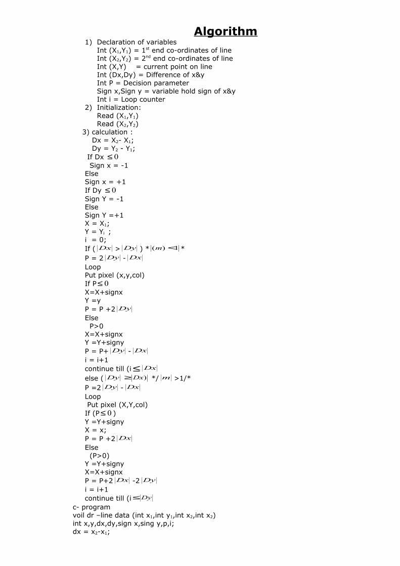
Algorithm1) Declaration of variables
Int (X1,Y1) = 1st end co-ordinates of lineInt (X2,Y2) = 2nd end co-ordinates of lineInt (X,Y) = current point on lineInt (Dx,Dy) = Difference of x&yInt P = Decision parameter Sign x,Sign y = variable hold sign of x&yInt i = Loop counter
2) Initialization:Read (X1,Y1) Read (X2,Y2)
3) calculation : Dx = X2- X1; Dy = Y2 - Y1; If Dx 0≤ Sign x = -1Else Sign x = +1If Dy 0≤Sign Y = -1Else Sign Y =+1X = X1;Y = Yi ;i = 0;If ( Dx > Dy ) * 1)( <m *P = 2 Dy - DxLoop Put pixel (x,y,col)If P 0≤X=X+signxY =yP = P +2 DyElse P>0X=X+signxY =Y+signyP = P+ Dy - Dxi = i+1continue till (i ≤ Dxelse ( Dy )Dx≥ */ m >1/*P =2 Dy - Dx Loop Put pixel (X,Y,col)If (P 0≤ )Y =Y+signyX = x;P = P +2 DxElse (P>0)Y =Y+signyX=X+signxP = P+2 Dx -2 Dyi = i+1continue till (i Dy≤
c- programvoil dr –line data (int x1,int y1,int x2,int x2)int x,y,dx,dy,sign x,sing y,p,i;dx = x2-x1;
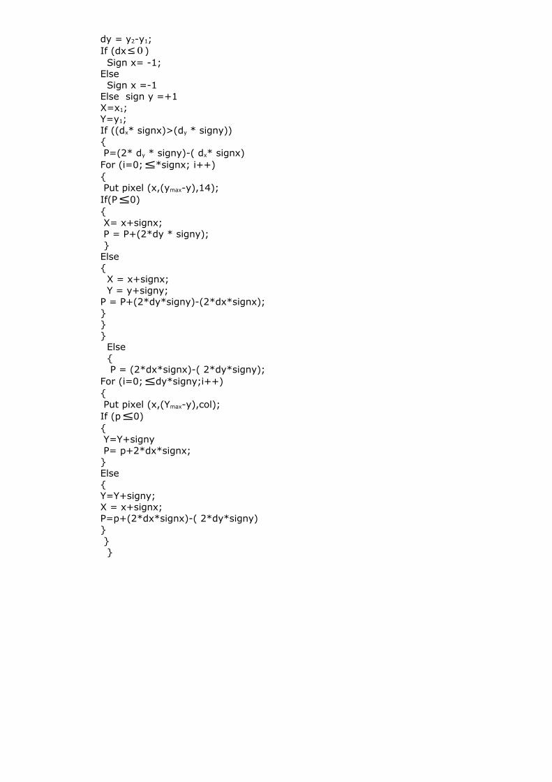
dy = y2-y1;If (dx 0≤ ) Sign x= -1;Else Sign x =-1Else sign y =+1X=x1;Y=y1;If ((dx* signx)>(dy * signy)){ P=(2* dy * signy)-( dx* signx)For (i=0; ≤*signx; i++){ Put pixel (x,(ymax-y),14);If(P ≤0){ X= x+signx; P = P+(2*dy * signy); }Else{ X = x+signx; Y = y+signy;P = P+(2*dy*signy)-(2*dx*signx);}}} Else { P = (2*dx*signx)-( 2*dy*signy);For (i=0; ≤dy*signy;i++){ Put pixel (x,(Ymax-y),col);If (p ≤0){ Y=Y+signy P= p+2*dx*signx;}Else{Y=Y+signy;X = x+signx;P=p+(2*dx*signx)-( 2*dy*signy)} } }
Calculate absolute value of horizontal & vertical differenceDX = abs(X2 - X1)DY = abs(Y2 - Y1)
C1 = 2 * DYC2 = 2 * (DY - DX)
Calculate the initial decision parameterP = 2 * DY - DX
P =P +C2
Y =Y +1
X = X + 1
If P < 0
Put a pixel at ( X,Y )
P = P + C1
Y = Y
If X<XEND
Stop
Input Start Point Coordinate X1 , X2
& End Point Coordinate Y1, Y2 of the line
If X1 > X
2
X = X2
Y = Y2
XEND = X1
X = X1
Y = Y1
XEND =
Put a pixel at ( X,Y )
1
1
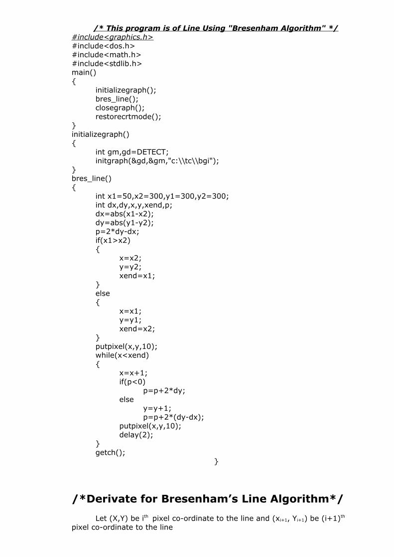
/* This program is of Line Using "Bresenham Algorithm" */#include<graphics.h>#include<dos.h>#include<math.h>#include<stdlib.h>main(){
initializegraph();bres_line();closegraph();restorecrtmode();
}initializegraph(){
int gm,gd=DETECT;initgraph(&gd,&gm,"c:\\tc\\bgi");
}bres_line(){
int x1=50,x2=300,y1=300,y2=300;int dx,dy,x,y,xend,p;dx=abs(x1-x2);dy=abs(y1-y2);p=2*dy-dx;if(x1>x2){
x=x2;y=y2;xend=x1;
}else{
x=x1;y=y1;xend=x2;
}putpixel(x,y,10);while(x<xend){
x=x+1;if(p<0)
p=p+2*dy;else
y=y+1;p=p+2*(dy-dx);
putpixel(x,y,10);delay(2);
}getch();
}
/*Derivate for Bresenham’s Line Algorithm*/
Let (X,Y) be ith pixel co-ordinate to the line and (xi+1, Yi+1) be (i+1)th pixel co-ordinate to the line
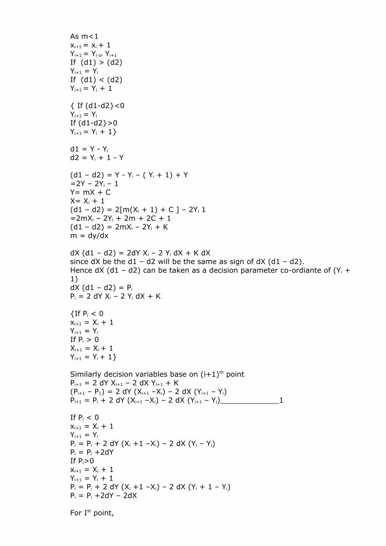
As m<1xi+1 = xi + 1Yi+1 = Yi or Yi+1
If (d1) > (d2)Yi+1 = Yi If (d1) < (d2)Yi+1 = Yi + 1
{ If (d1-d2}<0Yi+1 = Yi If (d1-d2}>0Yi+1 = Yi + 1}
d1 = Y - Yi
d2 = Yi + 1 - Y
(d1 – d2) = Y - Yi – ( Yi + 1) + Y=2Y – 2Yi – 1Y= mX + CX= Xi + 1(d1 – d2) = 2[m(Xi + 1) + C ] – 2Yi 1=2mXi – 2Yi + 2m + 2C + 1(d1 – d2) = 2mXi – 2Yi + Km = dy/dx
dX (d1 – d2) = 2dY Xi – 2 Yi dX + K dXsince dX be the d1 – d2 will be the same as sign of dX (d1 – d2).Hence dX (d1 – d2) can be taken as a decision parameter co-ordiante of (Yi + 1)dX (d1 – d2) = Pi Pi = 2 dY Xi – 2 Yi dX + K
{If Pi < 0xi+1 = Xi + 1Yi+1 = Yi If Pi > 0 Xi+1 = Xi + 1Yi+1 = Yi + 1}
Similarly decision variables base on (i+1)th point Pi+1 = 2 dY Xi+1 – 2 dX Yi+1 + K(Pi+1 – P1) = 2 dY (Xi+1 –Xi) – 2 dX (Yi+1 – Yi)Pi+1 = Pi + 2 dY (Xi+1 –Xi) – 2 dX (Yi+1 – Yi)_____________1
If Pi < 0xi+1 = Xi + 1Yi+1 = Yi Pi = Pi + 2 dY (Xi +1 –Xi) – 2 dX (Yi – Yi)Pi = Pi +2dYIf Pi>0xi+1 = Xi + 1Yi+1 = Yi + 1Pi = Pi + 2 dY (Xi +1 –Xi) – 2 dX (Yi + 1 – Yi)Pi = Pi +2dY – 2dX
For Ist point,
Xi = Xi
Yi = Yi Pi = 2 dY Xi – 2 dX Yi + K dXSince Ist point also on the lineYi = mXi + C Pi = 2 dY Xi – 2 dX Yi + dX (2m + 2C – 1)Pi = 2 dY – dX
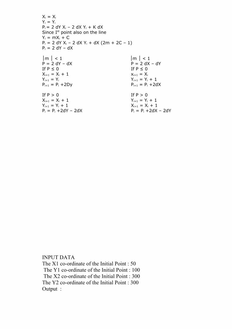
│m < 1 m < 1│ │ │P = 2 dY – dX P = 2 dX – dY If P ≤ 0 If P ≤ 0 Xi+1 = Xi + 1 xi+1 = Xi Yi+1 = Yi Yi+1 = Yi + 1Pi+1 = Pi +2Dy Pi+1 = Pi +2dX
If P > 0 If P > 0 Xi+1 = Xi + 1 Yi+1 = Yi + 1Yi+1 = Yi + 1 Xi+1 = Xi + 1Pi = Pi +2dY – 2dX Pi = Pi +2dX – 2dY
INPUT DATAThe X1 co-ordinate of the Initial Point : 50 The Y1 co-ordinate of the Initial Point : 100 The X2 co-ordinate of the Initial Point : 300The Y2 co-ordinate of the Initial Point : 300Output :

EXPERIMENT N o. 2
Experiment No. 02
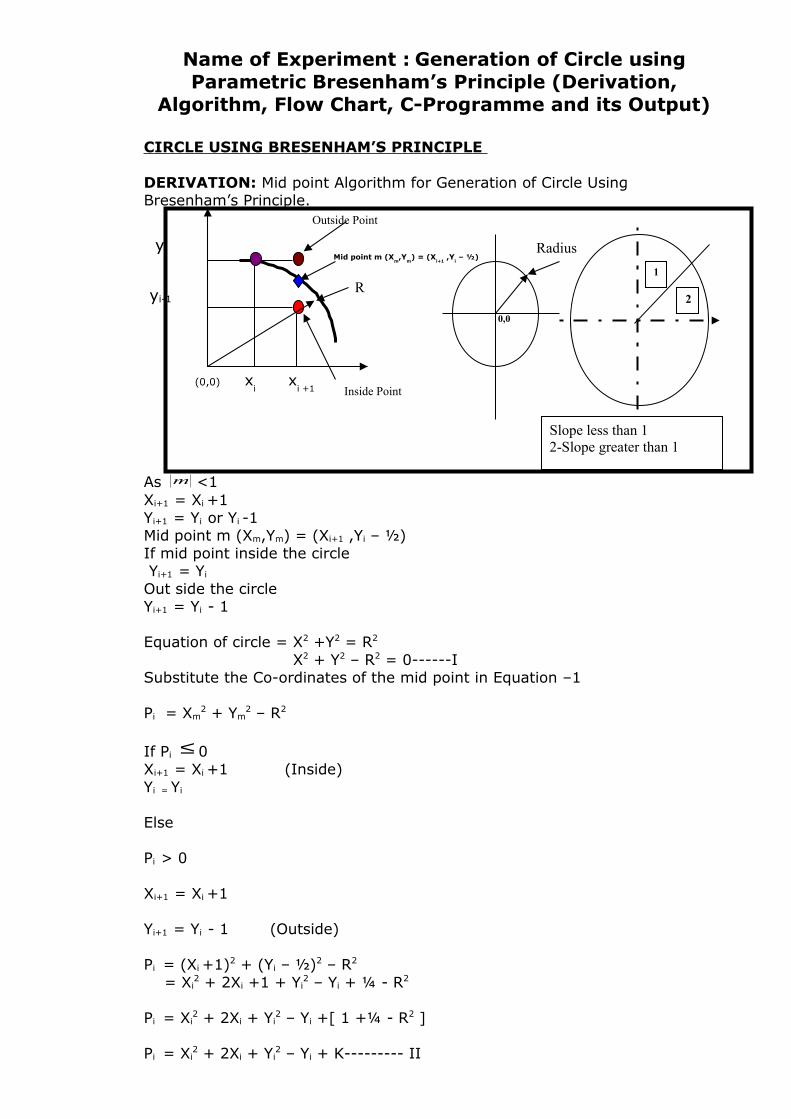
Name of Experiment : Generation of Circle using Parametric Bresenham’s Principle (Derivation,
Algorithm, Flow Chart, C-Programme and its Output)
CIRCLE USING BRESENHAM’S PRINCIPLE
DERIVATION: Mid point Algorithm for Generation of Circle Using Bresenham’s Principle.
As m <1Xi+1 = Xi +1Yi+1 = Yi or Yi -1Mid point m (Xm,Ym) = (Xi+1 ,Yi – ½)If mid point inside the circle Yi+1 = Yi
Out side the circleYi+1 = Yi - 1
Equation of circle = X2 +Y2 = R2
X2 + Y2 – R2 = 0------ISubstitute the Co-ordinates of the mid point in Equation –1 Pi = Xm
2 + Ym2 – R2
If Pi ≤ 0Xi+1 = Xi +1 (Inside)Yi = Yi
Else
Pi > 0
Xi+1 = Xi +1
Yi+1 = Yi - 1 (Outside)
Pi = (Xi +1)2 + (Yi – ½)2 – R2 = Xi
2 + 2Xi +1 + Yi2 – Yi + ¼ - R2
Pi = Xi2 + 2Xi + Yi
2 – Yi +[ 1 +¼ - R2 ]
Pi = Xi2 + 2Xi + Yi
2 – Yi + K--------- II
(0,0) xi
xi +1
R
0,0
Radius
Outside Point
Mid point m (Xm,Y
m) = (X
i+1 ,Y
i – ½)
Inside Point
1
2
Slope less than 12-Slope greater than 1
yi
yi-1
Where K = 1 +¼ - R2
.
. . Decision based Variable based on (i+1)th point
Pi+1 = (Xi +1)2 + 2(Xi +1) +( Yi+1 ) - Yi+1 +K----III
Subs tract III-II
Pi+1 - Pi = [(Xi +1)2 - Xi2] + 2 [(Xi +1) - Xi] + [Yi+1
2] – [Yi+1 - Yi]
Pi+1 = Pi + --------------------------------IV If Pi ≤ 0
Xi +1 = Xi +1
Yi+1 = Yi
Substitute in Equation IV ,We get
Pi+1 = Pi +[(Xi +1)2 - Xi2] + 2 (Xi +1 - Xi) + Yi
2 - Yi2] – [Yi - Yi]
= Pi + [ Xi2 + 2Xi +1- Xi
2 +2] = Pi +2Xi +1+2Pi+1 = Pi +2Xi + 3------------------------V
If P > 0Xi +1 = Xi +1Yi+1 = Yi - 1 Substitute in Equation IV,We get
Pi+1= Pi+[(Xi +1)2 - Xi2] + 2 [(Xi +1 - Xi)] + [(Yi - 1)2 - Yi
2 )]- [Yi -1- Yi]
= Pi+[ Xi2 + 2Xi +1- Xi
2 +2]+[ Yi2 - 2 Yi +1- Yi
2]+1 = Pi+[2Xi+3] + [-2Yi +2]
Pi+1= Pi+2Xi -2 Yi +5For finding Ist decision variable point (0,R) Xi=0 , Yi = RPi = Xm
2 + Ym2 – R2
=(Xi +1)2 + (Yi – ½)2 – R2
= (0+1)2 + (R-1/2)2 – R2
= 1 + R2 – R +1/4 – R2
P = 5/4 – R
P ≈ 1-R
Circle with Centre (Xc,Yc) X = X + Xc
Y = Y + Yc
ALGORITHM
1) Declaration of variables: Int (Xc,Yc)- Co-ordinate of Centre of circle Int R – Radius of Circle
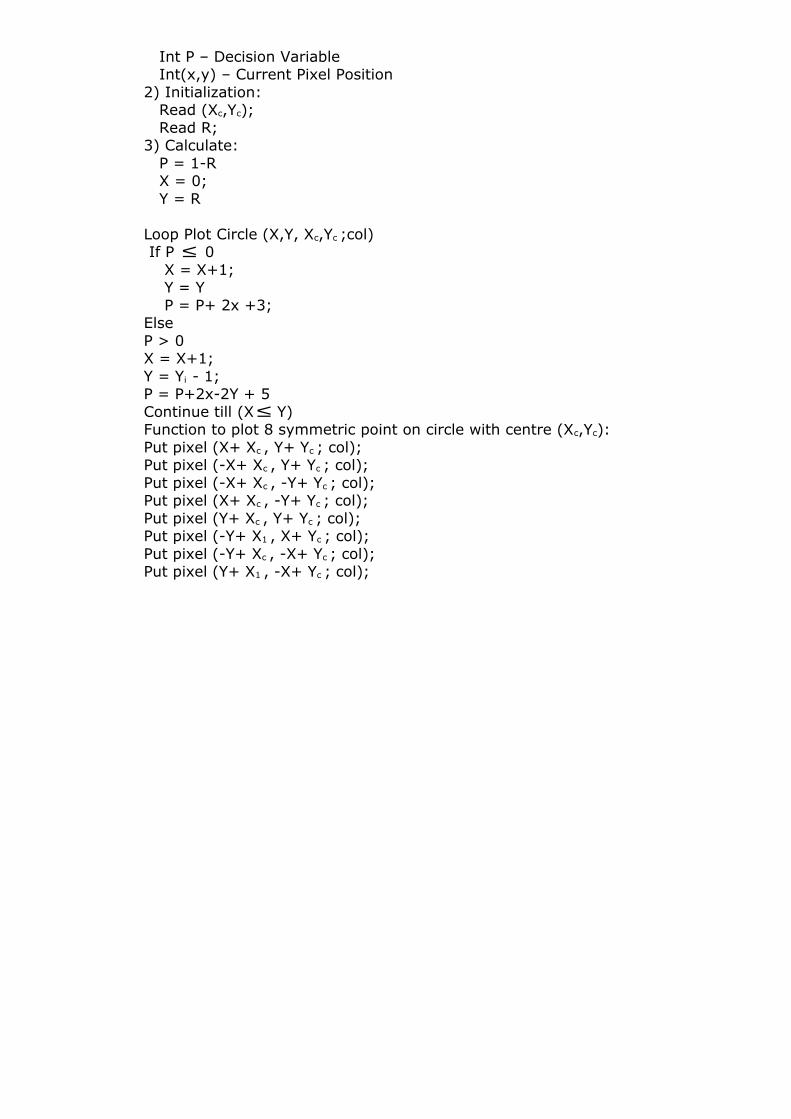
Int P – Decision Variable Int(x,y) – Current Pixel Position2) Initialization: Read (Xc,Yc); Read R;3) Calculate: P = 1-R X = 0; Y = R
Loop Plot Circle (X,Y, Xc,Yc ;col) If P ≤ 0 X = X+1; Y = Y P = P+ 2x +3;ElseP > 0X = X+1;Y = Yi - 1;P = P+2x-2Y + 5Continue till (X≤ Y)Function to plot 8 symmetric point on circle with centre (Xc,Yc):Put pixel (X+ Xc , Y+ Yc ; col);Put pixel (-X+ Xc , Y+ Yc ; col);Put pixel (-X+ Xc , -Y+ Yc ; col);Put pixel (X+ Xc , -Y+ Yc ; col);Put pixel (Y+ Xc , Y+ Yc ; col);Put pixel (-Y+ X1 , X+ Yc ; col);Put pixel (-Y+ Xc , -X+ Yc ; col);Put pixel (Y+ X1 , -X+ Yc ; col);
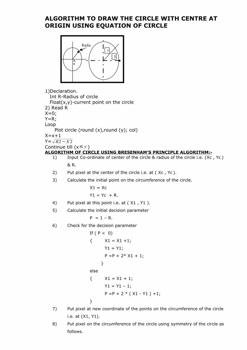
ALGORITHM TO DRAW THE CIRCLE WITH CENTRE AT ORIGIN USING EQUATION OF CIRCLE
1)Declaration. Int R-Radius of circle Float(x,y)-current point on the circle2) Read RX=0;Y=R;Loop Plot circle (round (x),round (y); col)X=x+1Y= 22 XR −Continue till (x y≤ )ALGORITHM OF CIRCLE USING BRESENHAM’S PRINCIPLE ALGORITHM:-
1) Input Co-ordinate of center of the circle & radius of the circle i.e. (Xc , Yc )
& R.
2) Put pixel at the center of the circle i.e. at ( Xc , Yc ).
3) Calculate the initial point on the circumference of the circle.
X1 = Xc
Y1 = Yc + R.
4) Put pixel at this point i.e. at ( X1 , Y1 ).
5) Calculate the initial decision parameter
P = 1 – R.
6) Check for the decision parameter
If ( P < 0)
{ X1 = X1 +1;
Y1 = Y1;
P =P + 2* X1 + 1;
}
else
{ X1 = X1 + 1;
Y1 = Y1 – 1;
P =P + 2 * ( X1 - Y1 ) +1;
}
7) Put pixel at new coordinate of the points on the circumference of the circle
i.e. at (X1, Y1).
8) Put pixel on the circumference of the circle using symmetry of the circle as
follows.
0,0
Radius 1
2
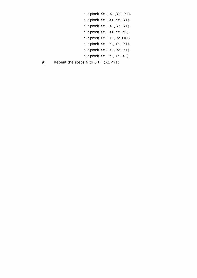
put pixel( Xc + X1 ,Yc +Y1).
put pixel( Xc – X1, Yc +Y1).
put pixel( Xc + X1, Yc –Y1).
put pixel( Xc – X1, Yc –Y1).
put pixel( Xc + Y1, Yc +X1).
put pixel( Xc – Y1, Yc +X1).
put pixel( Xc + Y1, Yc –X1).
put pixel( Xc – Y1, Yc –X1).
9) Repeat the steps 6 to 8 till (X1<Y1)
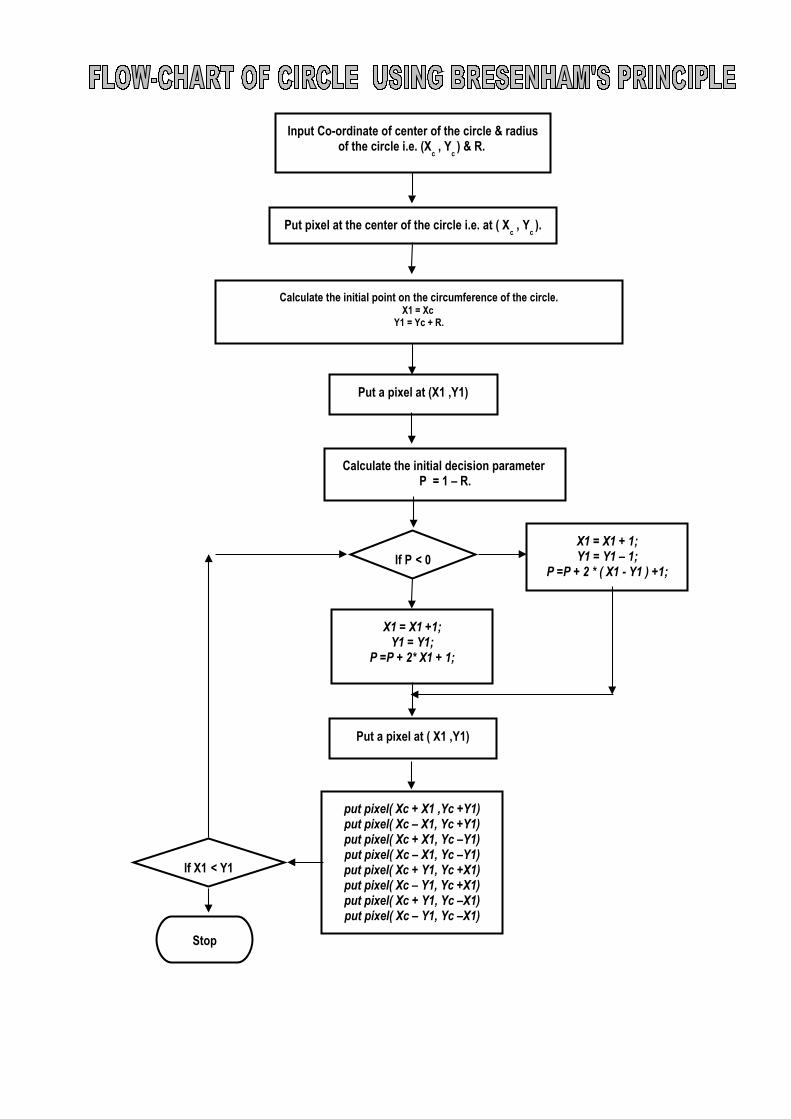
Put pixel at the center of the circle i.e. at ( Xc , Y
c ).
Calculate the initial point on the circumference of the circle.X1 = Xc
Y1 = Yc + R.
Input Co-ordinate of center of the circle & radius of the circle i.e. (X
c , Y
c ) & R.
Calculate the initial decision parameter P = 1 – R.
If P < 0
Put a pixel at (X1 ,Y1)
put pixel( Xc + X1 ,Yc +Y1)put pixel( Xc – X1, Yc +Y1)put pixel( Xc + X1, Yc –Y1)put pixel( Xc – X1, Yc –Y1)put pixel( Xc + Y1, Yc +X1)put pixel( Xc – Y1, Yc +X1)put pixel( Xc + Y1, Yc –X1)put pixel( Xc – Y1, Yc –X1)
Stop
X1 = X1 +1;Y1 = Y1;
P =P + 2* X1 + 1;
Put a pixel at ( X1 ,Y1)
X1 = X1 + 1;Y1 = Y1 – 1;
P =P + 2 * ( X1 - Y1 ) +1;
If X1 < Y1
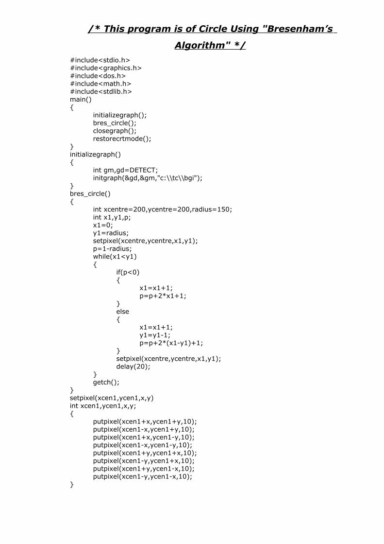
/* This program is of Circle Using "Bresenham’s
Algorithm" */
#include<stdio.h>#include<graphics.h>#include<dos.h>#include<math.h>#include<stdlib.h>main(){
initializegraph();bres_circle();closegraph();restorecrtmode();
}initializegraph(){
int gm,gd=DETECT;initgraph(&gd,&gm,"c:\\tc\\bgi");
}bres_circle(){
int xcentre=200,ycentre=200,radius=150;int x1,y1,p;x1=0;y1=radius;setpixel(xcentre,ycentre,x1,y1);p=1-radius;while(x1<y1){
if(p<0){
x1=x1+1;p=p+2*x1+1;
}else{
x1=x1+1;y1=y1-1;p=p+2*(x1-y1)+1;
}setpixel(xcentre,ycentre,x1,y1);delay(20);
}getch();
}setpixel(xcen1,ycen1,x,y)int xcen1,ycen1,x,y;{
putpixel(xcen1+x,ycen1+y,10);putpixel(xcen1-x,ycen1+y,10);putpixel(xcen1+x,ycen1-y,10);putpixel(xcen1-x,ycen1-y,10);putpixel(xcen1+y,ycen1+x,10);putpixel(xcen1-y,ycen1+x,10);putpixel(xcen1+y,ycen1-x,10);putpixel(xcen1-y,ycen1-x,10);
}
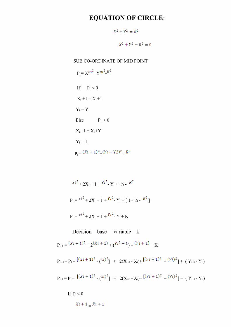
EQUATION OF CIRCLE:
SUB CO-ORDINATE OF MID POINT
Pi = X +Y -
If PI < 0
Xi +1 = Xi +1
Yi = Y
Else Pi > 0
Xi +1 = Xi +Y
Yi = 1
Pi = + -
+ 2Xi + 1 + - Yi + ¼ -
Pi = + 2Xi + 1 + - Yi + [ 1+ ¼ - ]
Pi = + 2Xi + 1 + - Yi + K
Decision base variable k
Pi+1 = + 2 + ( ) – + K
Pi +1 – P1 = - ( ] + 2(Xi+1 - Xi)+ – ] + ( Yi+1 - Yi )
Pi+1 = Pi + - ( ] + 2(Xi+1 - Xi)+ – ] + ( Yi+1 - Yi )
If Pi < 0
=
= Y
Pi+1 = Pi + 2Xi + 1 + 2
Pi+1 = Pi + 2Xi + 3
If P > 0
=
= Y – 1
= Pi+ 2Xi – 2yi + 5
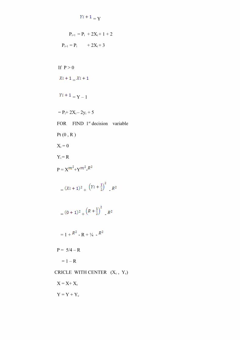
FOR FIND 1st decision variable
Pt (0 , R )
Xi = 0
Yi = R
P = X +Y -
= + -
= + -
= 1 + - R + ¼ -
P = 5/4 – R
= 1 – R
CRICLE WITH CENTER (Xc , Yc)
X = X+ Xc
Y = Y + Yc

INPUT DATA:The Radius of Circle : 150.The X coordinate center of circle : 200. The Y coordinate center of circle : 200.
Output :
EXPERIMENT N o. 3
Experiment No. 03
Name of Experiment: Generation of Ellipse and arc using parametric Equation and Bresenham’s Principle (Derivation, Algorithm, Flow Chart, C-Programme and its Output)
ELLIPSE USING BRESENHAM’S PRINCIPLE
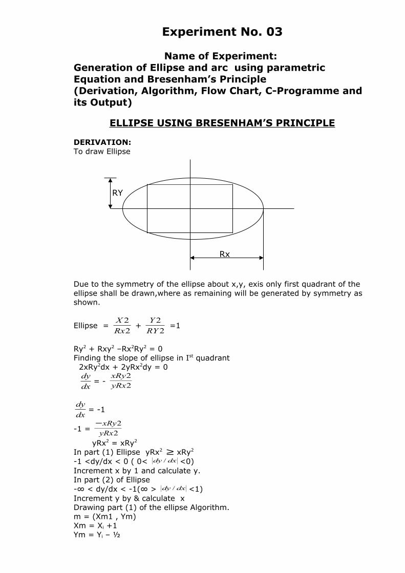
DERIVATION:To draw Ellipse
Due to the symmetry of the ellipse about x,y, exis only first quadrant of the ellipse shall be drawn,where as remaining will be generated by symmetry as shown.
Ellipse = 2
2
Rx
X +
2
2
RY
Y =1
Ry2 + Rxy2 –Rx2Ry2 = 0Finding the slope of ellipse in Ist quadrant 2xRy2dx + 2yRx2dy = 0
dx
dy= -
2
2
yRx
xRy
dx
dy= -1
-1 = 2
2
yRx
xRy−
yRx2 = xRy2
In part (1) Ellipse yRx2 ≥ xRy2
-1 <dy/dx < 0 ( 0< dxdy / <0)Increment x by 1 and calculate y.In part (2) of Ellipse-∞ < dy/dx < -1(∞ > dxdy / <1)Increment y by & calculate xDrawing part (1) of the ellipse Algorithm.m = (Xm1 , Ym)Xm = Xi +1Ym = Yi – ½
Rx
RY
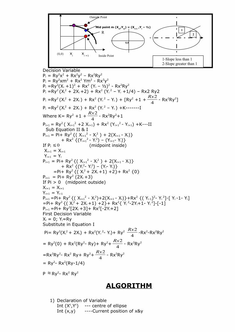
Decision VariablePi = Ry2x2 + Rx2y2 – Rx2Ry2
Pi = Ry2xm2 + Rx2 Ym2 - Rx2y2
Pi =Ry2(Xi +1)2 + Rx2 (Yi – ½)2 - Rx2Ry2
Pi =Ry2 (Xi2 + 2Xi
+2) + Rx2 (Yi 2 – Yi +1/4) – Rx2 Ry2
Pi =Ry2 (Xi2 + 2Xi ) + Rx2 (Yi
2 – Yi ) + [Ry2 +1 +4
2Rx- Rx2Ry2]
Pi =Ry2 (Xi2 + 2Xi ) + Rx2 (Yi
2 – Yi ) +K-------I
Where K= Ry2 +1 +4
2Rx- Rx2Ry2+1
Pi+1 = Ry2 ( Xi+12 +2 Xi+1) + Rx2 (Yi+1
2 - Yi+1) +K---II Sub Equation II & IPi+1 = Pi+ Ry2 {( Xi+1
2 - Xi2 ) + 2(Xi+1 - Xi)}
+ Rx2 {(Yi+12 - Yi
2) – (Yi+1- Yi)}If Pi 0≤ (midpoint inside) Xi+1 = Xi+1
Yi+1 = Yi
Pi+1 = Pi+ Ry2 {( Xi+12 - Xi
2 ) + 2(Xi+1 - Xi)} + Rx2 {(Yi
2- Yi2) – (Yi- Yi)}
=Pi+ Ry2 {( Xi2 + 2Xi +1) +2}+ Rx2 {0}
Pi+1 = Pi+ Ry2 (2Xi +3)If Pi > 0 (midpoint outside)Xi+1 = Xi+1
Yi+1 = Yi-1
Pi+1 =Pi+ Ry2 {( Xi+12 - Xi
2)+2(Xi+1 - Xi)}+Rx2 {( Yi-1)2- Yi 2]-[ Yi
-1- Yi]=Pi+ Ry2 {( Xi
2 + 2Xi +1) +2}+ Rx2{ Yi 2-2Yi+1- Yi
2]-[-1]Pi+1 =Pi+ Ry2[2Xi +3]+ Rx2[-2Yi+2]First Decision VariableXi = 0; Yi=RySubstitute in Equation I
Pi= Ry2(Xi2 + 2Xi) + Rx2(Yi
2- Yi)+ Ry2 4
2Rx-Rx2-Rx2Ry2
= Ry2(0) + Rx2(Ry2- Ry)+ Ry2+4
2Rx- Rx2Ry2
=Rx2Ry2- Rx2 Ry+ Ry2+4
2Rx- Rx2Ry2
= Ry2- Rx2(Ry-1/4)
P ≈ Ry2- Rx2 Ry2
ALGORITHM
1) Declaration of VariableInt (Xc,Yc) --- centre of ellipseInt (x,y) ----Current position of x&y
(0,0) xi
xi +1
R
0,0
Outside Point
Mid point m (Xm,Y
m) = (X
i+1 ,Y
i – ½)
Inside Point
1
2
1-Slope less than 12-Slope greater than 1
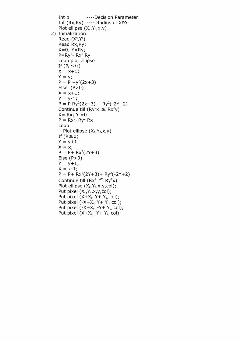
Int p ----Decision ParameterInt (Rx,Ry) ---- Radius of X&YPlot ellipse (Xc,Yc,x,y)
2) InitializationRead (Xc,Yc) Read Rx,Ry;X=0; Y=Ry;P=Ry2- Rx2 RyLoop plot ellipseIf (Pi 0≤ )X = x+1;Y = y;P = P +y2(2x+3)Else (P>0)X = x+1;Y = y-1;P = P Ry2(2x+3) + Ry2(-2Y+2)Continue tiil (Ry2x ≤ Rx2y)X= Rx; Y =0P = Rx2- Ry2 RxLoop Plot ellipse (Xc,Yc,x,y)If (P≤0)Y = y+1;X = x;P = P+ Rx2(2Y+3)Else (P>0)Y = y+1;X = x-1;P = P+ Rx2(2Y+3)+ Ry2(-2Y+2)Continue till (Rx2 ≤ Ry2x)Plot ellipse (Xc,Yc,x,y,col);Put pixel (Xc,Yc,x,y,col);Put pixel (X+Xc, Y+ Yc, col);Put pixel (-X+Xc, Y+ Yc, col);Put pixel (-X+Xc, -Y+ Yc, col);Put pixel (X+Xc, -Y+ Yc, col);

/* This program is of ELLIPSE Using "Bresenham Algorithm" */
Function to draw ellipseVoid draw ellipse (int Xc ,int Yc,int Rx,int Ry){Int x,y;Float p;Long Sx,Rx,Sy,Ry ;SqRx=Rx*Rx;SqRy=Ry*RyP=SqRy-SqRx*Ry+SqRx/4For(x=1;(SqRy*x) <= (SqRx*y); x++)(Plotellipse (Xc,Yc,X,Y)If(p<=0)P=p+SqRy*(2*x+3) ;Else{y--;p=p+SqRy*(2*x+3)}}X=rx;Y=0;P=SqRx-SqRy*Rx+SqRy*(2-2xy)For(y=1;(SqRx*y)<=(SqRy*x);y++){Plotellipse (Xc,Yc,x,y)If(p<=0)P=p+SqRx*(2*y+3) ;{Elsex-- ;p=p+SqRx*(2*y+3)+SqRx*(2-2*x) ;}}
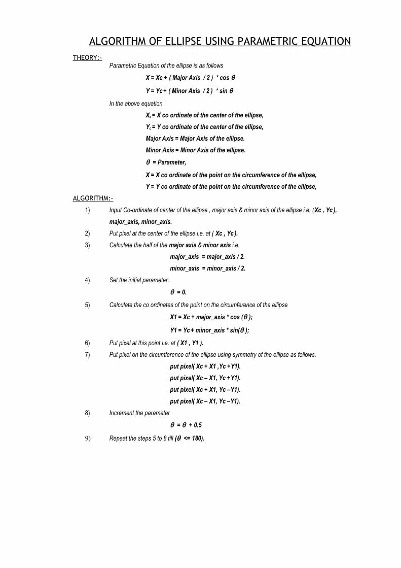
ALGORITHM OF ELLIPSE USING PARAMETRIC EQUATIONTHEORY:-
Parametric Equation of the ellipse is as follows
X = Xc + ( Major Axis / 2 ) * cos θ
Y = Yc + ( Minor Axis / 2 ) * sin θ
In the above equation
Xc = X co ordinate of the center of the ellipse,
Yc = Y co ordinate of the center of the ellipse,
Major Axis = Major Axis of the ellipse.
Minor Axis = Minor Axis of the ellipse.
θ = Parameter,
X = X co ordinate of the point on the circumference of the ellipse,
Y = Y co ordinate of the point on the circumference of the ellipse,
ALGORITHM:-
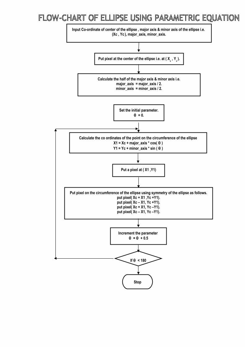
1) Input Co-ordinate of center of the ellipse , major axis & minor axis of the ellipse i.e. (Xc , Yc ),
major_axis, minor_axis.
2) Put pixel at the center of the ellipse i.e. at ( Xc , Yc ).
3) Calculate the half of the major axis & minor axis i.e.
major_axis = major_axis / 2.
minor_axis = minor_axis / 2.
4) Set the initial parameter.
θ = 0.
5) Calculate the co ordinates of the point on the circumference of the ellipse
X1 = Xc + major_axis * cos (θ );
Y1 = Yc + minor_axis * sin(θ );
6) Put pixel at this point i.e. at ( X1 , Y1 ).
7) Put pixel on the circumference of the ellipse using symmetry of the ellipse as follows.
put pixel( Xc + X1 ,Yc +Y1).
put pixel( Xc – X1, Yc +Y1).
put pixel( Xc + X1, Yc –Y1).
put pixel( Xc – X1, Yc –Y1).
8) Increment the parameter
θ = θ + 0.5
9) Repeat the steps 5 to 8 till (θ <= 180).
Put pixel at the center of the ellipse i.e. at ( Xc , Y
c ).
Calculate the half of the major axis & minor axis i.e.major_axis = major_axis / 2.minor_axis = minor_axis / 2.
Input Co-ordinate of center of the ellipse , major axis & minor axis of the ellipse i.e. (Xc , Yc
), major_axis, minor_axis.
Set the initial parameter.θ = 0.
Increment the parameter θ = θ + 0.5
Stop
Put pixel on the circumference of the ellipse using symmetry of the ellipse as follows.put pixel( Xc + X1 ,Yc +Y1).put pixel( Xc – X1, Yc +Y1).put pixel( Xc + X1, Yc –Y1).put pixel( Xc – X1, Yc –Y1).
Put a pixel at ( X1 ,Y1)
Calculate the co ordinates of the point on the circumference of the ellipseX1 = Xc + major_axis * cos( θ )Y1 = Yc + minor_axis * sin ( θ )
If θ < 180
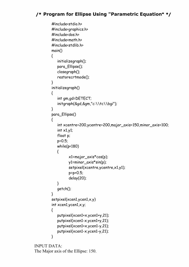
/* Program for Ellipse Using "Parametric Equation" */
#include<stdio.h>#include<graphics.h>#include<dos.h>#include<math.h>#include<stdlib.h>main(){
initializegraph();para_Ellipse();closegraph();restorecrtmode();
}initializegraph(){
int gm,gd=DETECT;initgraph(&gd,&gm,"c:\\tc\\bgi");
}para_Ellipse(){
int xcentre=200,ycentre=200,major_axis=150,minor_axis=100;int x1,y1;float p;p=0.5;while(p<180){
x1=major_axis*cos(p);y1=minor_axis*sin(p);setpixel(xcentre,ycentre,x1,y1);p=p+0.5;delay(20);
}getch();
}setpixel(xcen1,ycen1,x,y)int xcen1,ycen1,x,y;{
putpixel(xcen1+x,ycen1+y,21);putpixel(xcen1-x,ycen1+y,21);putpixel(xcen1+x,ycen1-y,21);putpixel(xcen1-x,ycen1-y,21);
}
INPUT DATA:The Major axis of the Ellipse: 150.
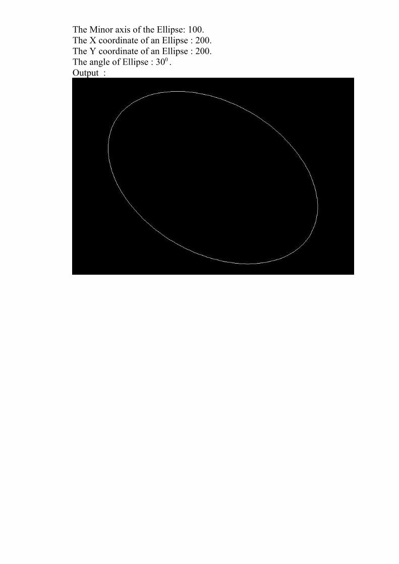
The Minor axis of the Ellipse: 100.The X coordinate of an Ellipse : 200.The Y coordinate of an Ellipse : 200.The angle of Ellipse : 300 .Output :

EXPERIMENT N o. 4
Experiment No.:04
Name of Experiment:Generation of Hyperbola using Parametric and
Bresnham’s Principle
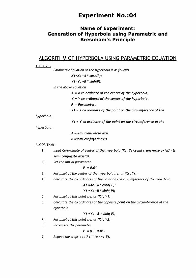
ALGORITHM OF HYPERBOLA USING PARAMETRIC EQUATIONTHEORY: -
Parametric Equation of the hyperbola is as follows
X1=Xc +A * cosh(P);
Y1=Yc +B * sinh(P);
In the above equation
Xc = X co ordinate of the center of the hyperbola,
Yc = Y co ordinate of the center of the hyperbola,
P = Parameter,
X1 = X co ordinate of the point on the circumference of the
hyperbola,
Y1 = Y co ordinate of the point on the circumference of the
hyperbola,
A =semi transverse axis
B =semi conjugate axis
ALGORITHM: -
1) Input Co-ordinate of center of the hyperbola (Xc, Yc),semi transverse axis(A) &
semi conjugate axis(B).
2) Set the initial parameter.
P = 0.01
3) Put pixel at the center of the hyperbola i.e. at (Xc, Yc).
4) Calculate the co ordinates of the point on the circumference of the hyperbola
X1 =Xc +A * cosh( P);
Y1 =Yc +B * sinh( P);
5) Put pixel at this point i.e. at (X1, Y1).
6) Calculate the co ordinates of the opposite point on the circumference of the
hyperbola
Y1 =Yc – B * sinh( P);
7) Put pixel at this point i.e. at (X1, Y2).
8) Increment the parameter
P = p + 0.01.
9) Repeat the steps 4 to 7 till (p <=1.5).
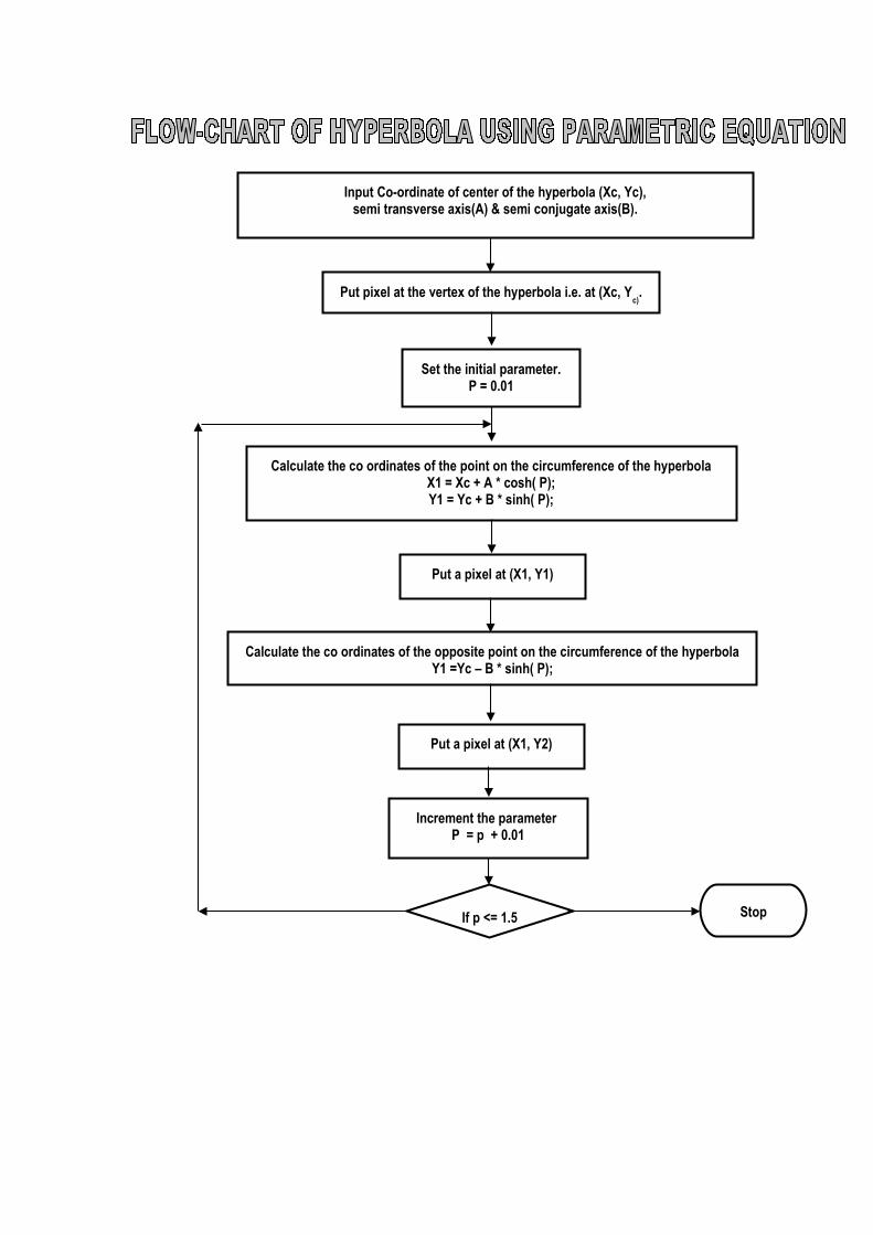
Put pixel at the vertex of the hyperbola i.e. at (Xc, Yc).
Input Co-ordinate of center of the hyperbola (Xc, Yc),semi transverse axis(A) & semi conjugate axis(B).
Set the initial parameter.P = 0.01
Increment the parameter P = p + 0.01
Stop
Calculate the co ordinates of the opposite point on the circumference of the hyperbolaY1 =Yc – B * sinh( P);
Put a pixel at (X1, Y1)
Calculate the co ordinates of the point on the circumference of the hyperbolaX1 = Xc + A * cosh( P);Y1 = Yc + B * sinh( P);
If p <= 1.5
Put a pixel at (X1, Y2)
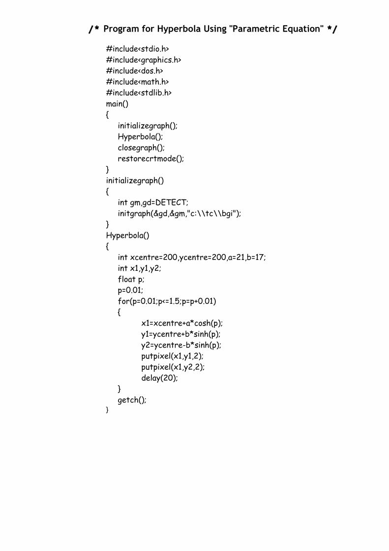
/* Program for Hyperbola Using "Parametric Equation" */
#include<stdio.h>#include<graphics.h>#include<dos.h>#include<math.h>#include<stdlib.h>main(){
initializegraph();Hyperbola();closegraph();restorecrtmode();
}initializegraph(){
int gm,gd=DETECT;initgraph(&gd,&gm,"c:\\tc\\bgi");
}Hyperbola(){
int xcentre=200,ycentre=200,a=21,b=17;int x1,y1,y2;float p;p=0.01;for(p=0.01;p<=1.5;p=p+0.01){
x1=xcentre+a*cosh(p);y1=ycentre+b*sinh(p);y2=ycentre-b*sinh(p);putpixel(x1,y1,2);putpixel(x1,y2,2);delay(20);
}getch();
}
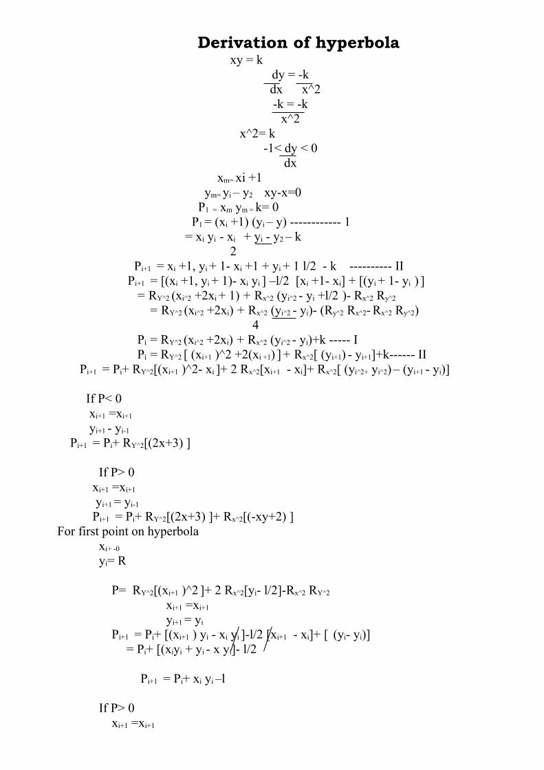
Derivation of hyperbola xy = k
dy = -k dx x^2
-k = -kx^2
x^2= k-1< dy < 0
dx xm= xi +1 ym= yi – y2 xy-x=0 P1 = xm ym = k= 0 P1 = (xi +1) (yi – y) ------------ 1 = xi yi - xi + yi - y2 – k 2
Pi+1 = xi +1, yi + 1- xi +1 + yi + 1 l/2 - k ---------- II Pi+1 = [(xi +1, yi + 1)- xi yi ] –l/2 [xi +1- xi] + [(yi + 1- yi ) ]
= RY^2 (xi^2 +2xi + 1) + Rx^2 (yi^2 - yi +l/2 )- Rx^2 Ry^2
= RY^2 (xi^2 +2xi) + Rx^2 (yi^2 - yi)- (Ry^2 Rx^2- Rx^2 Ry^2) 4 Pi = RY^2 (xi^2 +2xi) + Rx^2 (yi^2 - yi)+k ----- I Pi = RY^2 [ (xi+1 )^2 +2(xi +1) ] + Rx^2[ (yi+1) - yi+1]+k------ II Pi+1 = Pi+ RY^2[(xi+1 )^2- xi ]+ 2 Rx^2[xi+1 - xi]+ Rx^2[ (yi^2+ yi^2) – (yi+1 - yi)] If P< 0 xi+1 =xi+1
yi+1 - yi-1
Pi+1 = Pi+ RY^2[(2x+3) ]
If P> 0 xi+1 =xi+1
yi+1 = yi-1
Pi+1 = Pi+ RY^2[(2x+3) ]+ Rx^2[(-xy+2) ] For first point on hyperbola
xi+ -0
yi= R P= RY^2[(xi+1 )^2 ]+ 2 Rx^2[yi- l/2]-Rx^2 RY^2
xi+1 =xi+1
yi+1 = yi
Pi+1 = Pi+ [(xi+1 ) yi - xi yi ]-l/2 [xi+1 - xi]+ [ (yi- yi)] = Pi+ [(xiyi + yi - x yi]- l/2
Pi+1 = Pi+ xi yi –l If P> 0
xi+1 =xi+1
yi+1 = yi-1
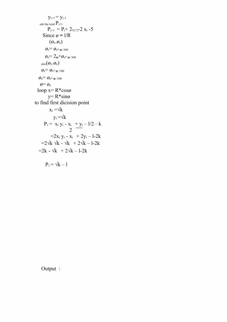
sub the total Pi+1
Pi+1 = Pi+ 2Yi^2-2 xi -5 Since ø = l/R (øs>øe) øs= øs* /360
øe= 2+øe* /360
also(øs<øe) øs= øs* /100
øe= øe* /100
ø= øs
loop x= R*cosø
y= R*sinø
to find first dicision point xi =√k
yi =√k P1 = xi yi - xi + yi – l/2 – k 2 =2xi yi - xi + 2yi – l-2k
=2√k √k - √k + 2√k – l-2k
=2k - √k + 2√k – l-2k
P1 = √k – l
Output :
EXPERIMENT N o. 5
Experiment No.:05
Name of Experiment:Generation of Parabola using Parametric and
Bresnhm’s Algorithm
ALGORITHM OF PARABOLA USING PARAMETRIC EQUATIONTHEORY:-
Parametric Equation of the parabola is as follows
X = Xc + (distance between focus & vertex * p * p)
Y = Yc + ( 2 * distance between focus & vertex * p)
In the above equation
Xc = X co ordinate of the vertex of the parabola,
Yc = Y co ordinate of the vertex of the parabola,
p = Parameter,
X = X co ordinate of the point on the circumference of the parabola,
Y = Y co ordinate of the point on the circumference of the parabola,
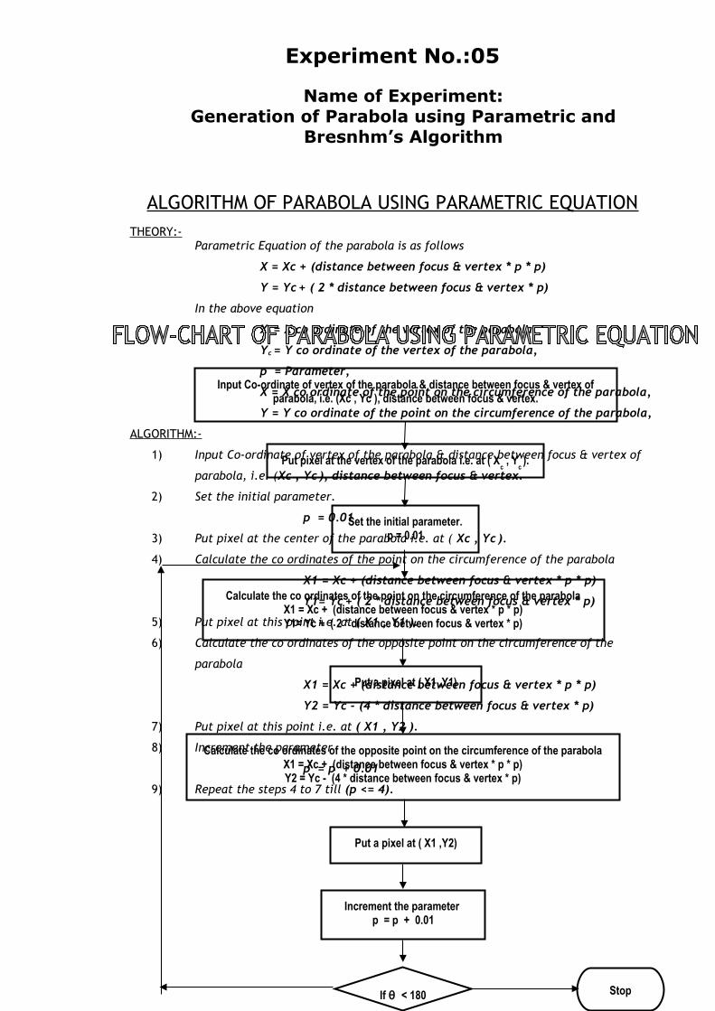
ALGORITHM:-
1) Input Co-ordinate of vertex of the parabola & distance between focus & vertex of
parabola, i.e. (Xc , Yc ), distance between focus & vertex.
2) Set the initial parameter.
p = 0.01
3) Put pixel at the center of the parabola i.e. at ( Xc , Yc ).
4) Calculate the co ordinates of the point on the circumference of the parabola
X1 = Xc + (distance between focus & vertex * p * p)
Y1= Yc + ( 2 * distance between focus & vertex * p)
5) Put pixel at this point i.e. at ( X1 , Y1 ).
6) Calculate the co ordinates of the opposite point on the circumference of the
parabola
X1 = Xc + (distance between focus & vertex * p * p)
Y2 = Yc - (4 * distance between focus & vertex * p)
7) Put pixel at this point i.e. at ( X1 , Y2 ).
8) Increment the parameter
p = p + 0.01
9) Repeat the steps 4 to 7 till (p <= 4).
Put pixel at the vertex of the parabola i.e. at ( Xc , Y
c ).
Input Co-ordinate of vertex of the parabola & distance between focus & vertex of parabola, i.e. (Xc , Yc ), distance between focus & vertex.
Set the initial parameter.p = 0.01
Increment the parameter p = p + 0.01
Stop
Calculate the co ordinates of the opposite point on the circumference of the parabolaX1 = Xc + (distance between focus & vertex * p * p)Y2 = Yc - (4 * distance between focus & vertex * p)
Put a pixel at ( X1 ,Y1)
Calculate the co ordinates of the point on the circumference of the parabolaX1 = Xc + (distance between focus & vertex * p * p)Y1= Yc + ( 2 * distance between focus & vertex * p)
If θ < 180
Put a pixel at ( X1 ,Y2)

/* Program for Parabola Using "Parametric Equation" */
#include<stdio.h>#include<graphics.h>#include<dos.h>#include<math.h>#include<stdlib.h>main(){
initializegraph();parabola();closegraph();restorecrtmode();
}initializegraph(){
int gm,gd=DETECT;initgraph(&gd,&gm,"c:\\tc\\bgi");
}parabola(){
int xcentre=200,ycentre=200,distance_between_focus_and_vertex=20;
int x1,y1;float p;p=0.01;for(p=0.01;p<=4;p=p+0.01){
x1=xcentre+(distance_between_focus_and_vertex*p*p);y1=ycentre+(2*distance_between_focus_and_vertex*p);putpixel(x1,y1,2);putpixel(x1,y1-
(4*distance_between_focus_and_vertex*p),2);delay(20);
}getch();
}
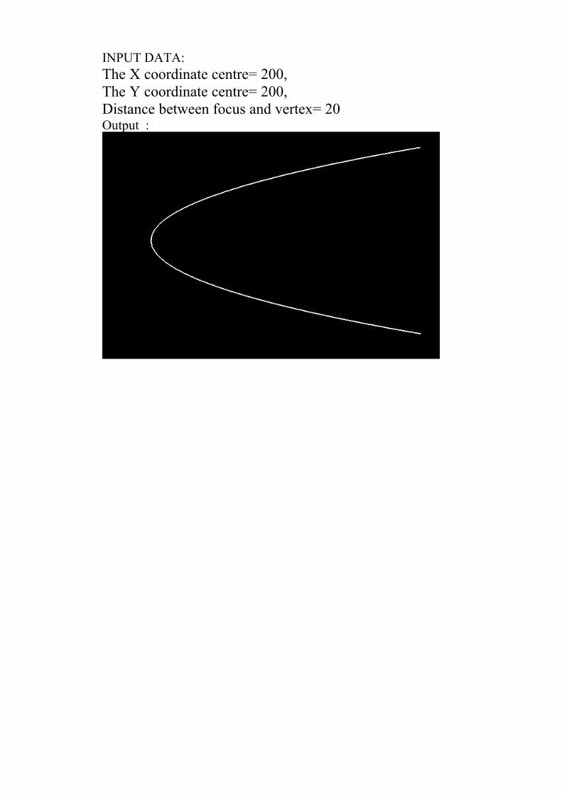
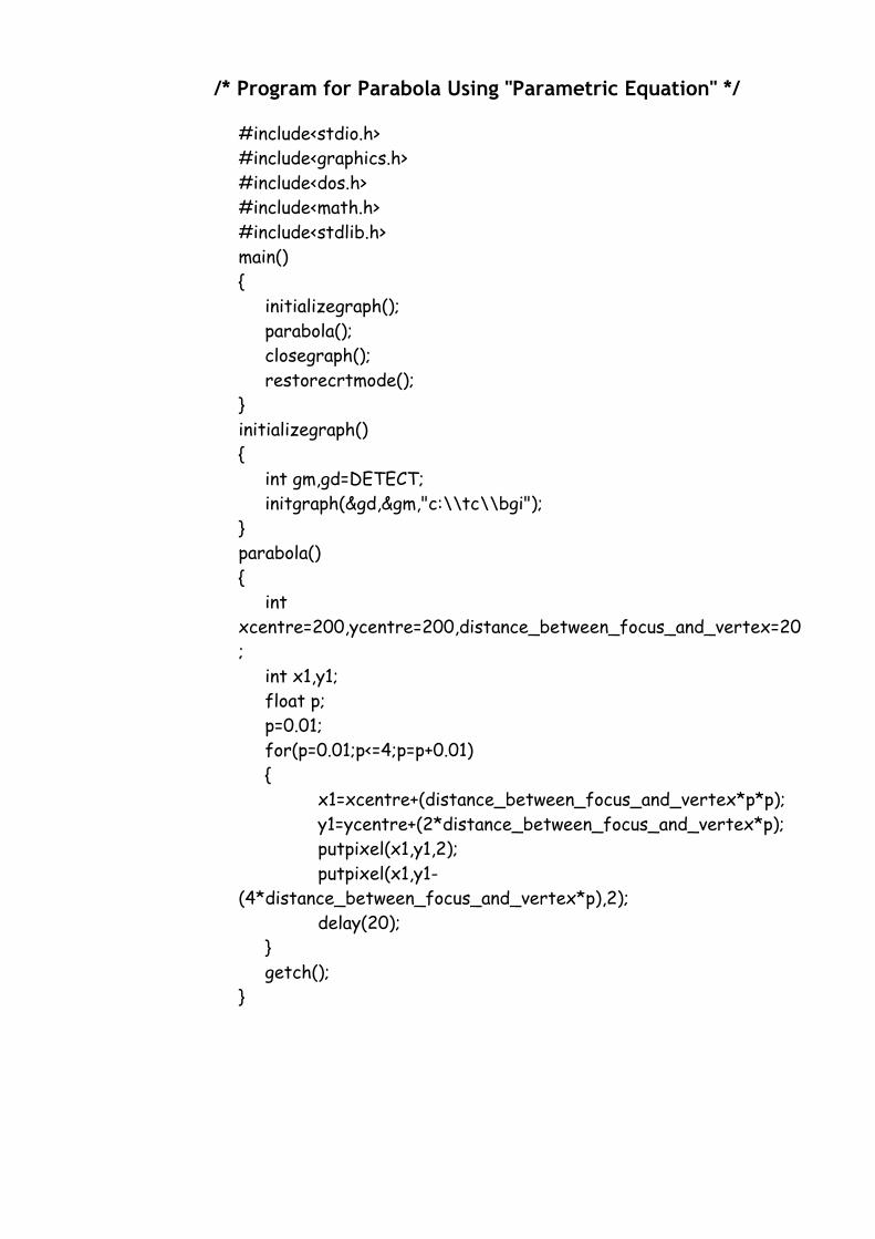
INPUT DATA:The X coordinate centre= 200,The Y coordinate centre= 200,Distance between focus and vertex= 20Output :
EXPERIMENT N o. 6
Experiment No.:06
Name of Experiment:Generation of Synthetic Curves (Bezier and B-Spline)
ALGORITHM FOR B-SPLINE CURVES
ALGORITHM: -
1) Initialization of all the required parameters.
2) Enter the co-ordinates of four control point Px(4) and Py(4).
3) For four control points degree (n) is three.
4) Calculate the knot vector as:
0 j<k
Uj = j-k+1 k j n
n-k+2 j>n
where,
0 j n +k
for the range of u,
0 u n – k + 2
5) Calculate the B-spline function for the four control points as
Ni,k(u) = (u-uj) Ni,k-1(u)/(ui,k+1-ui) + (ui+k-u) Ni+1,k-1(u)/(ui+k-ui-1)
Where,
Ni,j = 1, ui u ui+1
O, otherwise
Considering 0/0 = 0 if the denominator in above equation becomes
zero
6) Calculate the corresponding four control points on the B-Spline curve as
P(u)x = Px[0]*N0,4+Px[1]*N1,4+Px[2]*N2,4+Px[3]*N3,4 for 0 u 1
P(u)y = Py[0]*N0,4+Py[1]*N1,4+Py[2]*N2,4+Py[3]*N3,4 for 0 u 1
By incrementing u in small step.
7) Graphics Initilisation.
8) Plot the co-ordinates
/* Program for "B-Spline" */
#include<math.h>#include<graphics.h>#include<stdlib.h>#include<stdio.h>#include<conio.h> void main(void){
int i,j,n,m,m1,k,x,s,k1; float Umax,Umin,u,Uk[10],N[20][20],px[4],py[4]={0},X[4]={0},Y[4]={0}; float num1=0,num2=0,deno1=0,deno2=0,Ax[4]={0},Ay[4]={0},sumX=0,sumY=0; int gdriver = DETECT, gmode, errorcode; clrscr(); printf("\nEnter the number of control point "); scanf("%d",&k); printf("\nEnter the coordinate of control point "); for(i=0;i<=k-1;i++)
{ scanf("%f",&px[i]); scanf("%f",&py[i]);}
k1=k;n=k-1;Umin=0;Umax=n-k+2;s=n+k;for(j=0;j<=n+k;j++){
if(j<k) Uk[j]=0;
else{
if(j>=k&&j<=n) Uk[j]=j-k+1;else{ if(j>n) Uk[j]=n-k+2;}}}for(i=0;i<=n;i++) { for(k=1;k<=n;k++) { if((i+k)>s) continue; else { if(Uk[i+k-1]-Uk[i]==0&&Uk[i+k]-Uk[i+1]==0){ N[i][k]=0;} }}}for(i=0;i<=n;i++){ if(u>=Uk[i]||u<=Uk[i+1]) N[i][1]=1;else N[i][1]=0; }
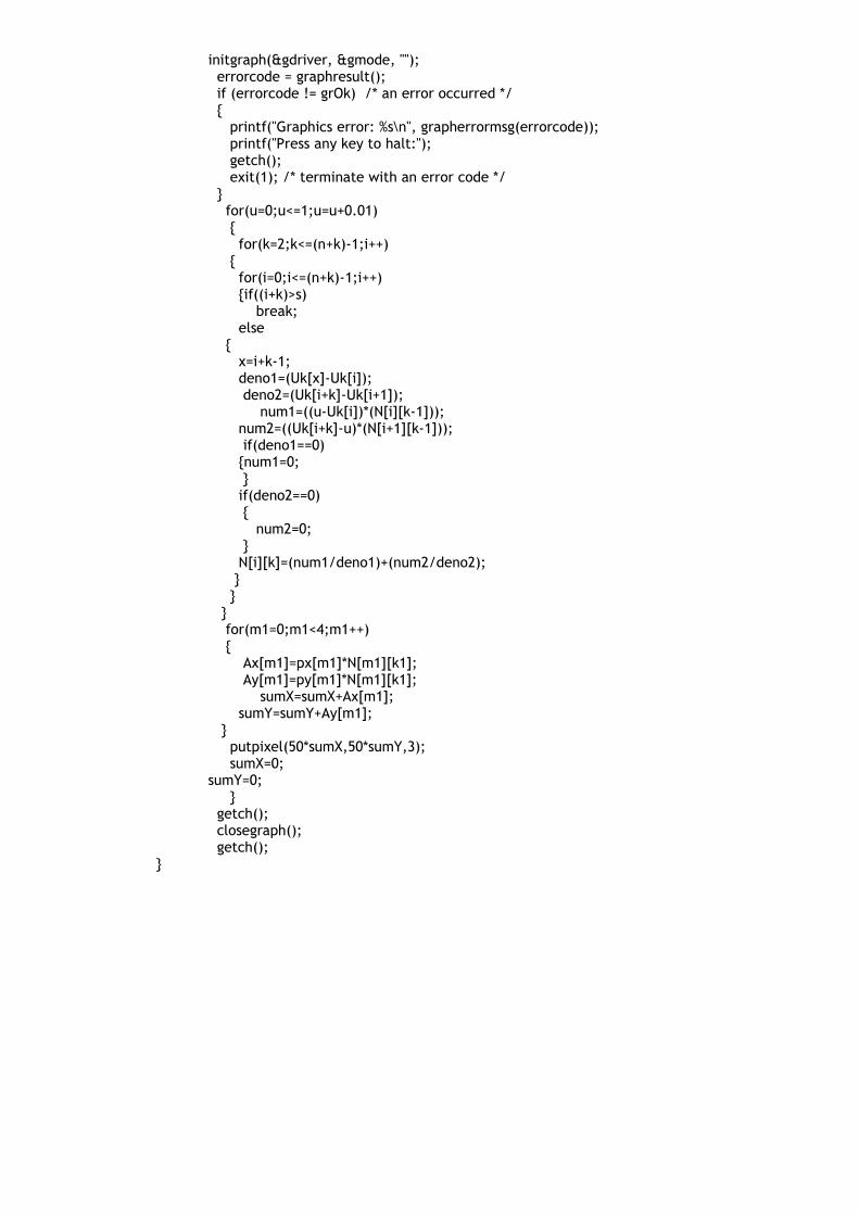
initgraph(&gdriver, &gmode, ""); errorcode = graphresult(); if (errorcode != grOk) /* an error occurred */ { printf("Graphics error: %s\n", grapherrormsg(errorcode)); printf("Press any key to halt:"); getch(); exit(1); /* terminate with an error code */ } for(u=0;u<=1;u=u+0.01) { for(k=2;k<=(n+k)-1;i++) { for(i=0;i<=(n+k)-1;i++) {if((i+k)>s) break; else { x=i+k-1; deno1=(Uk[x]-Uk[i]); deno2=(Uk[i+k]-Uk[i+1]);
num1=((u-Uk[i])*(N[i][k-1])); num2=((Uk[i+k]-u)*(N[i+1][k-1])); if(deno1==0) {num1=0; } if(deno2==0) { num2=0; } N[i][k]=(num1/deno1)+(num2/deno2); } } } for(m1=0;m1<4;m1++) { Ax[m1]=px[m1]*N[m1][k1]; Ay[m1]=py[m1]*N[m1][k1];
sumX=sumX+Ax[m1]; sumY=sumY+Ay[m1]; } putpixel(50*sumX,50*sumY,3); sumX=0;sumY=0; } getch(); closegraph(); getch();
}

EXPERIMENT N o. 7
Experiment No.:07
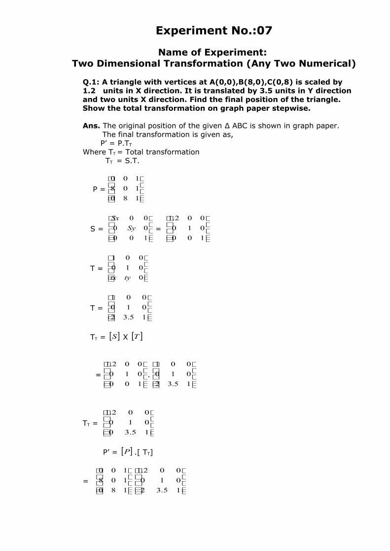
Name of Experiment: Two Dimensional Transformation (Any Two Numerical)
Q.1: A triangle with vertices at A(0,0),B(8,0),C(0,8) is scaled by 1.2 units in X direction. It is translated by 3.5 units in Y direction and two units X direction. Find the final position of the triangle. Show the total transformation on graph paper stepwise.
Ans. The original position of the given ∆ ABC is shown in graph paper. The final transformation is given as, P’ = P.TT Where TT = Total transformation TT = S.T.
P =
180
108
100
S =
100
00
00
Sy
Sx
=
100
010
002.1
T =
0
010
001
tytx
T =
15.32
010
001
TT = [ ]S X [ ]T
=
100
010
002.1
.
15.32
010
001
TT =
15.30
010
002.1
P’ = [ ]P .[ TT]
=
180
108
100
15.32
010
002.1
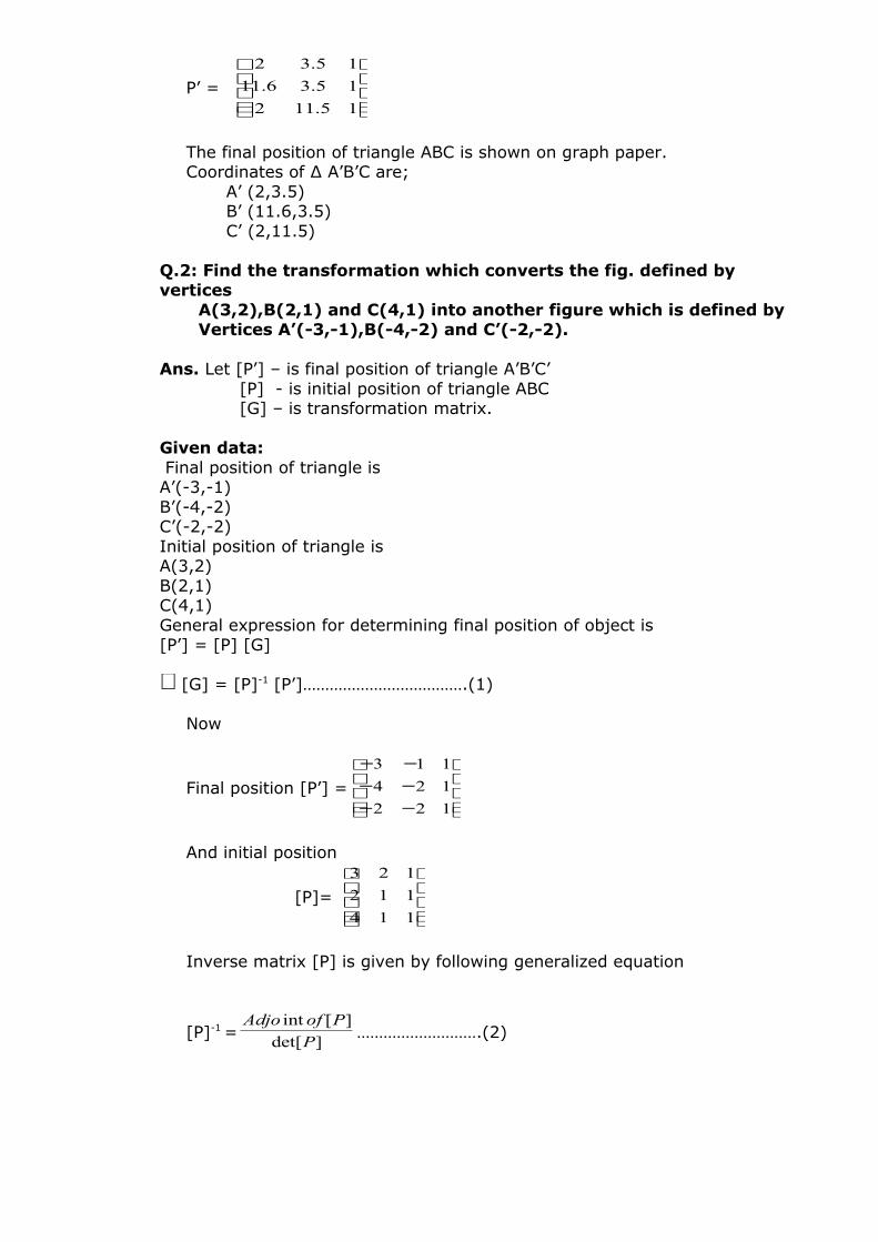
P’ =
15.112
15.36.11
15.32
The final position of triangle ABC is shown on graph paper.Coordinates of ∆ A’B’C are; A’ (2,3.5) B’ (11.6,3.5) C’ (2,11.5)
Q.2: Find the transformation which converts the fig. defined by vertices A(3,2),B(2,1) and C(4,1) into another figure which is defined by Vertices A’(-3,-1),B(-4,-2) and C’(-2,-2).
Ans. Let [P’] – is final position of triangle A’B’C’ [P] - is initial position of triangle ABC [G] – is transformation matrix. Given data: Final position of triangle isA’(-3,-1)B’(-4,-2)C’(-2,-2)Initial position of triangle is A(3,2)B(2,1)C(4,1)General expression for determining final position of object is [P’] = [P] [G]
∴[G] = [P]-1 [P’]……………………………….(1)
Now
Final position [P’] =
−−−−−−
122
124
113
And initial position
[P]=
114
112
123
Inverse matrix [P] is given by following generalized equation
[P]-1 =]det[
][int
P
PofAdjo……………………….(2)
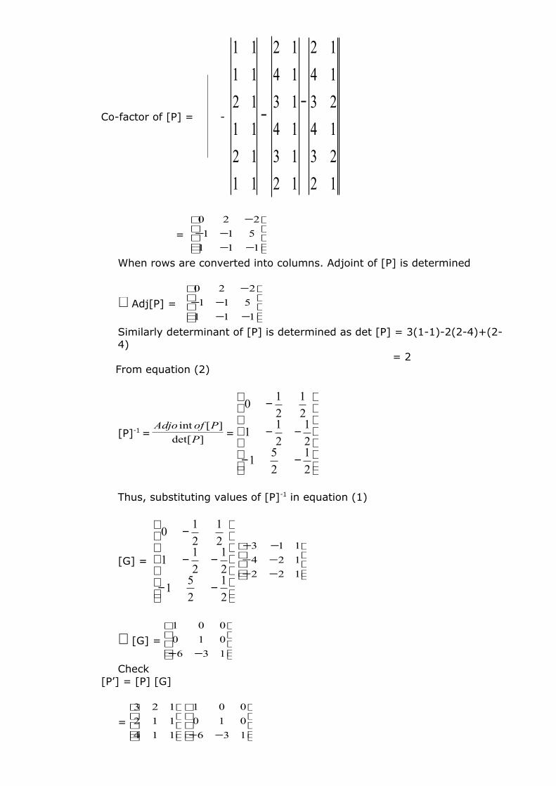
Co-factor of [P] = -
12
23
14
23
14
12
12
13
14
13
14
12
11
12
11
12
11
11
−−
=
−−−−
−
111
511
220
When rows are converted into columns. Adjoint of [P] is determined
∴Adj[P] =
−−−−
−
111
511
220
Similarly determinant of [P] is determined as det [P] = 3(1-1)-2(2-4)+(2-4) = 2
From equation (2)
[P]-1 =]det[
][int
P
PofAdjo=
−−
−−
−
2
1
2
51
2
1
2
11
2
1
2
10
Thus, substituting values of [P]-1 in equation (1)
[G] =
−−
−−
−
2
1
2
51
2
1
2
11
2
1
2
10
−−−−−−
122
124
113
∴[G] =
−− 136
010
001
Check [P’] = [P] [G]
=
114
112
123
−− 136
010
001
=
−−−−−−
122
124
113
Hence verified.Problem No. 3 :
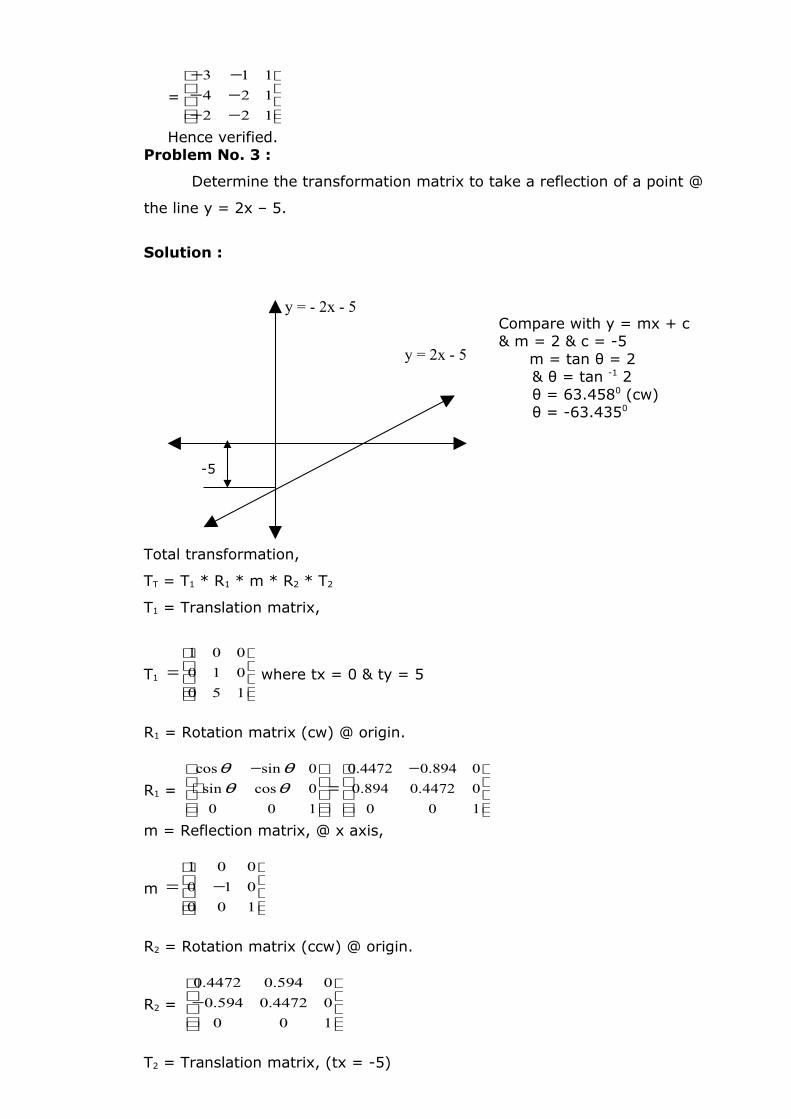
Determine the transformation matrix to take a reflection of a point @
the line y = 2x – 5.
Solution :
Compare with y = mx + c & m = 2 & c = -5
m = tan θ = 2& θ = tan -1 2θ = 63.4580 (cw)θ = -63.4350
Total transformation,
TT = T1 * R1 * m * R2 * T2
T1 = Translation matrix,
T1
=
150
010
001
where tx = 0 & ty = 5
R1 = Rotation matrix (cw) @ origin.
R1 =
−=
+
−
100
04472.0894.0
0894.04472.0
100
0cossin
0sincos
θθθθ
m = Reflection matrix, @ x axis,
m
−=
100
010
001
R2 = Rotation matrix (ccw) @ origin.
R2 =
−
100
04472.0594.0
0594.04472.0
T2 = Translation matrix, (tx = -5)
-5
y = - 2x - 5
y = 2x - 5
T2 =
− 150
010
001
TT =
−∗
−∗
−∗
−∗
150
010
001
000
04472.0894.0
0894.04472.0
100
010
001
100
04472.0894.0
0894.04472.0
150
010
001
TT =
−
−
1005.2995.3
0599.0799.0
0799.0599.0
reqd. total transformation matrix.
Problem 4:An equilateral ∆ ABC with length of side to units is to be transformed
into an isosceles ∆ ABC. With attitude 2.5 times the altitude of equilateral
triangle co-ordinate of pt1. A (10,5).
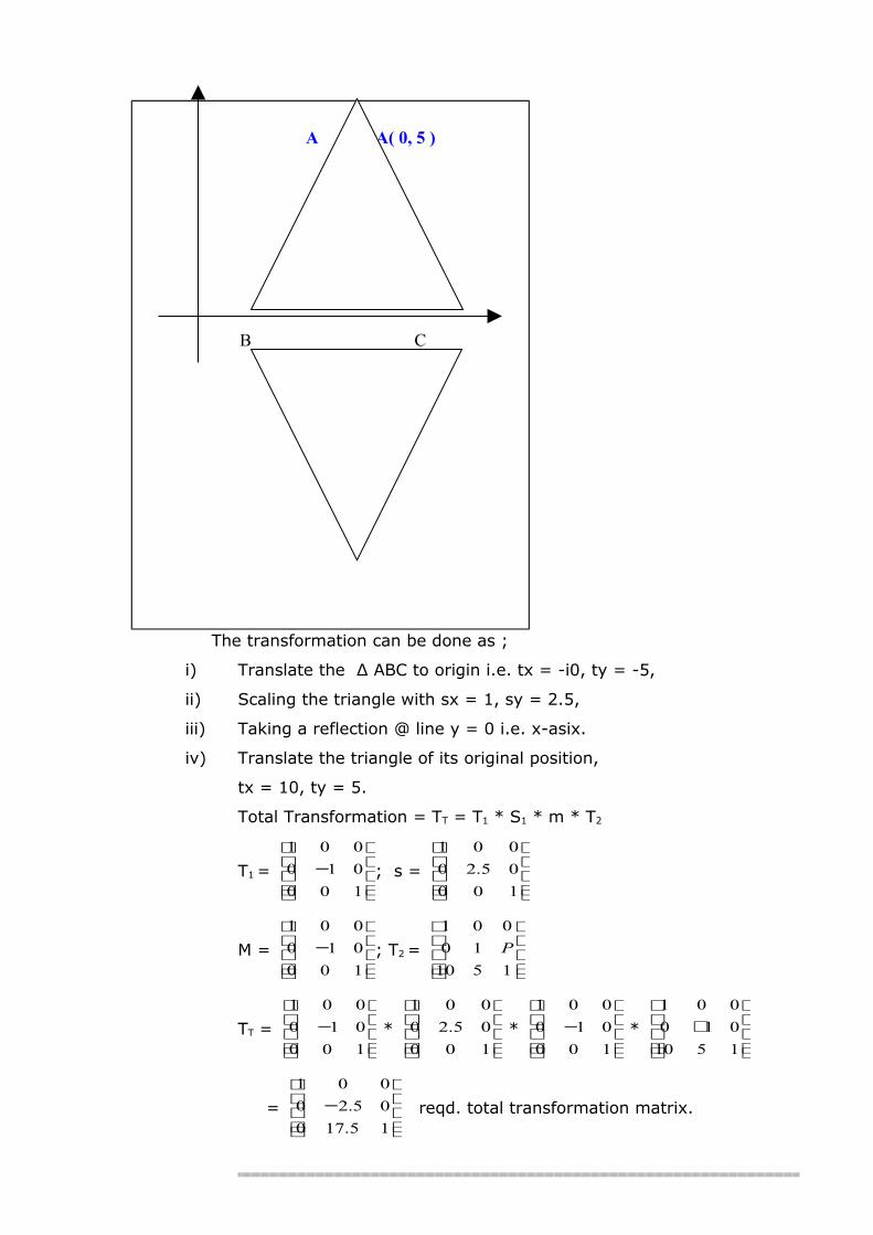
Solution :
The transformation can be done as ;
i) Translate the ∆ ABC to origin i.e. tx = -i0, ty = -5,
ii) Scaling the triangle with sx = 1, sy = 2.5,
iii) Taking a reflection @ line y = 0 i.e. x-asix.
iv) Translate the triangle of its original position,
tx = 10, ty = 5.
Total Transformation = TT = T1 * S1 * m * T2
T1 =
−
100
010
001
; s =
100
05.20
001
M =
−
100
010
001
; T2 =
1510
10
001
P
TT =
−
100
010
001
*
100
05.20
001
*
−
100
010
001
*
+
1510
010
001
=
−
15.170
05.20
001
reqd. total transformation matrix.
A A( 0, 5 )
B C
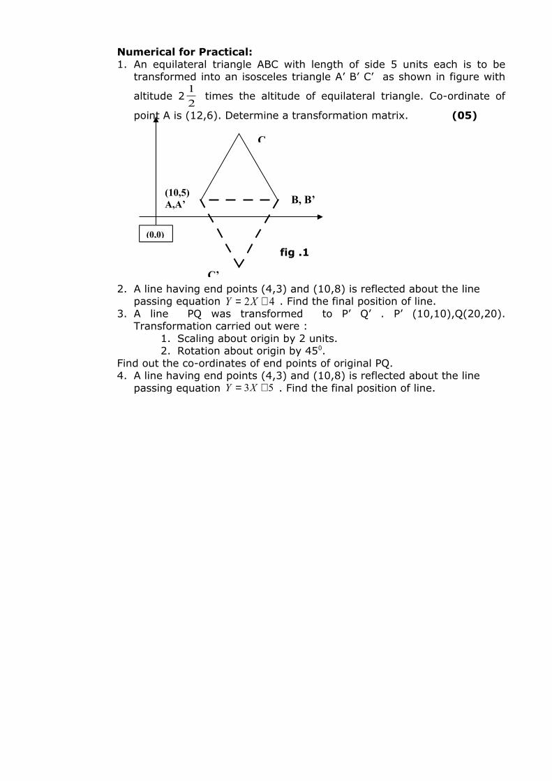
Numerical for Practical:1. An equilateral triangle ABC with length of side 5 units each is to be
transformed into an isosceles triangle A’ B’ C’ as shown in figure with
altitude 22
1 times the altitude of equilateral triangle. Co-ordinate of
point A is (12,6). Determine a transformation matrix. (05)
2. A line having end points (4,3) and (10,8) is reflected about the line passing equation 42 += XY . Find the final position of line.
3. A line PQ was transformed to P’ Q’ . P’ (10,10),Q(20,20). Transformation carried out were :
1. Scaling about origin by 2 units.2. Rotation about origin by 450.
Find out the co-ordinates of end points of original PQ. 4. A line having end points (4,3) and (10,8) is reflected about the line
passing equation 53 += XY . Find the final position of line.
fig .1
C
B, B’(10,5)A,A’
C’
(0,0)
EXPERIMENT N o. 8
Experiment No.:08
Name of Experiment:Three Dimensional Transformation (Any Two Numerical)
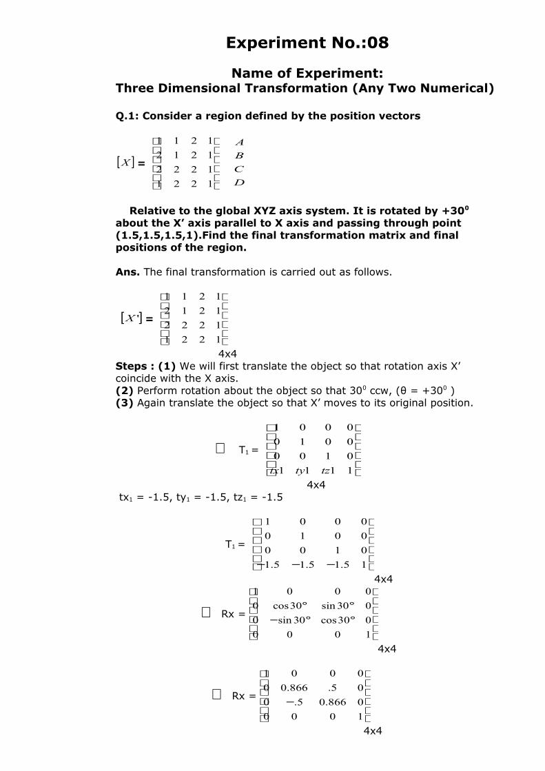
Q.1: Consider a region defined by the position vectors
[ ]X =
1221
1222
1212
1211
D
C
B
A
Relative to the global XYZ axis system. It is rotated by +300 about the X’ axis parallel to X axis and passing through point (1.5,1.5,1.5,1).Find the final transformation matrix and final positions of the region.
Ans. The final transformation is carried out as follows.
[ ]'X =
1221
1222
1212
1211
4x4Steps : (1) We will first translate the object so that rotation axis X’ coincide with the X axis.(2) Perform rotation about the object so that 300 ccw, (θ = +300 )(3) Again translate the object so that X’ moves to its original position.
∴ T1 =
1111
0100
0010
0001
tztytx
4x4 tx1 = -1.5, ty1 = -1.5, tz1 = -1.5
T1 =
−−− 15.15.15.1
0100
0010
0001
4x4
∴ Rx =
°°−°°
1000
030cos30sin0
030sin30cos0
0001
4x4
∴ Rx =
−1000
0866.05.0
05.866.00
0001
4x4
T2 =
15.15.15.1
0100
0010
0001
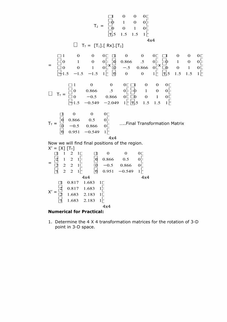
4x4 ∴ TT = [T1].[ Rx].[T2]
=
−−− 15.15.15.1
0100
0010
0001
x
−1000
0866.05.0
05.866.00
0001
x
15.15.15.1
0100
0010
0001
∴ TT =
−−−−
1049.2549.05.1
0866.05.00
05.866.00
0001
15.15.15.1
0100
0010
0001
TT =
−−
1549.0951.00
0866.05.00
05.0866.00
0001
…..Final Transformation Matrix
4x4 Now we will find final positions of the region.X’ = [X] [TT]
=
1221
1222
1212
1211
−−
1549.0951.00
0866.05.00
05.0866.00
0001
4x4 4x4
X’ =
1183.2683.11
1183.2683.12
1683.1817.02
1683.1817.01
4x4Numerical for Practical:
1. Determine the 4 X 4 transformation matrices for the rotation of 3-D point in 3-D space.
EXPERIMENT N o. 9
Experiment No.:09
Name of Experiment:Algorithm and C-Program to generate machine
components
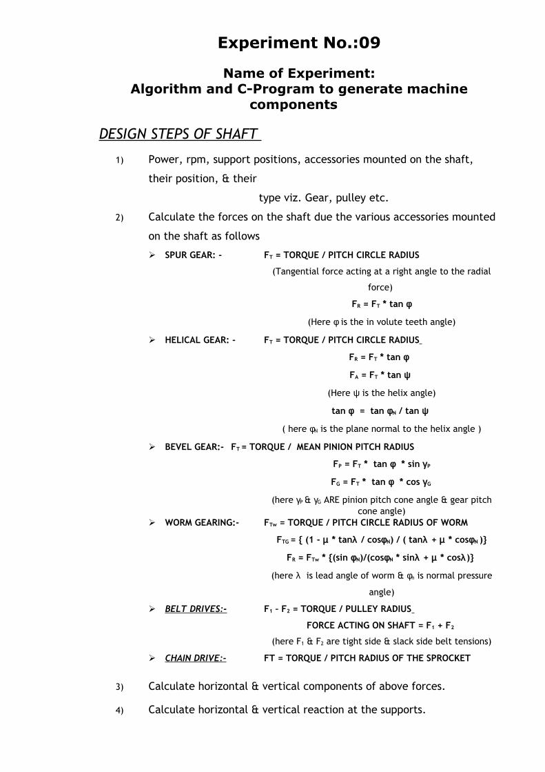
DESIGN STEPS OF SHAFT
1) Power, rpm, support positions, accessories mounted on the shaft,
their position, & their
type viz. Gear, pulley etc.
2) Calculate the forces on the shaft due the various accessories mounted
on the shaft as follows
SPUR GEAR: - FT = TORQUE / PITCH CIRCLE RADIUS
(Tangential force acting at a right angle to the radial
force)
FR = FT * tan φ
(Here φ is the in volute teeth angle)
HELICAL GEAR: - FT = TORQUE / PITCH CIRCLE RADIUS
FR = FT * tan φ
FA = FT * tan ψ
(Here ψ is the helix angle)
tan φ = tan φN / tan ψ
( here φN is the plane normal to the helix angle )
BEVEL GEAR:- FT = TORQUE / MEAN PINION PITCH RADIUS
FP = FT * tan φ * sin γP
FG = FT * tan φ * cos γG
(here γP & γG ARE pinion pitch cone angle & gear pitch cone angle)
WORM GEARING:- FTw = TORQUE / PITCH CIRCLE RADIUS OF WORM
FTG = { (1 - µ * tanλ / cosφN) / ( tanλ + µ * cosφN )}
FR = FTw * {(sin φN)/(cosφN * sinλ + µ * cosλ)}
(here λ is lead angle of worm & φn is normal pressure
angle)
BELT DRIVES:- F1 – F2 = TORQUE / PULLEY RADIUS
FORCE ACTING ON SHAFT = F1 + F2
(here F1 & F2 are tight side & slack side belt tensions)
CHAIN DRIVE:- FT = TORQUE / PITCH RADIUS OF THE SPROCKET
3) Calculate horizontal & vertical components of above forces.
4) Calculate horizontal & vertical reaction at the supports.
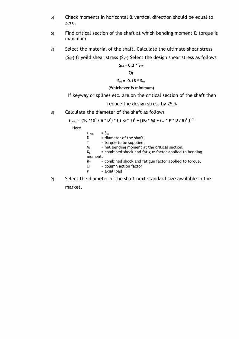
5) Check moments in horizontal & vertical direction should be equal to zero.
6) Find critical section of the shaft at which bending moment & torque is maximum.
7) Select the material of the shaft. Calculate the ultimate shear stress
(SUT) & yeild shear stress (SYT) Select the design shear stress as follows
SDS = 0.3 * SYT
Or
SDS = 0.18 * SUT
(Whichever is minimum)
If keyway or splines etc. are on the critical section of the shaft then
reduce the design stress by 25 %
8) Calculate the diameter of the shaft as follows
τ max = (16 *103 / π * D3) * { ( KT * T)2 + [(KB * M) + (∝ * P * D / 8)2 }1/2
Here τ max = SDS D = diameter of the shaft.T = torque to be supplied.M = net bending moment at the critical section.KB = combined shock and fatigue factor applied to bending moment.KT = combined shock and fatigue factor applied to torque.∝ = column action factorP = axial load
9) Select the diameter of the shaft next standard size available in the
market.
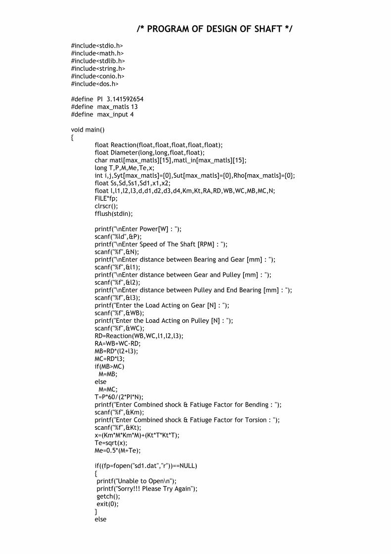
/* PROGRAM OF DESIGN OF SHAFT */
#include<stdio.h>#include<math.h>#include<stdlib.h>#include<string.h>#include<conio.h>#include<dos.h>
#define PI 3.141592654#define max_matls 13#define max_input 4
void main(){
float Reaction(float,float,float,float,float);float Diameter(long,long,float,float);char matl[max_matls][15],matl_in[max_matls][15];long T,P,M,Me,Te,x;int i,j,Syt[max_matls]={0},Sut[max_matls]={0},Rho[max_matls]={0};float Ss,Sd,Ss1,Sd1,x1,x2;float l,l1,l2,l3,d,d1,d2,d3,d4,Km,Kt,RA,RD,WB,WC,MB,MC,N;FILE*fp;clrscr();fflush(stdin);
printf("\nEnter Power[W] : ");scanf("%ld",&P);printf("\nEnter Speed of The Shaft [RPM] : ");scanf("%f",&N);printf("\nEnter distance between Bearing and Gear [mm] : ");scanf("%f",&l1);printf("\nEnter distance between Gear and Pulley [mm] : ");scanf("%f",&l2);printf("\nEnter distance between Pulley and End Bearing [mm] : ");scanf("%f",&l3);printf("Enter the Load Acting on Gear [N] : ");scanf("%f",&WB);printf("Enter the Load Acting on Pulley [N] : ");scanf("%f",&WC);RD=Reaction(WB,WC,l1,l2,l3);RA=WB+WC-RD;MB=RD*(l2+l3);MC=RD*l3;if(MB>MC) M=MB;else M=MC;T=P*60/(2*PI*N);printf("Enter Combined shock & Fatiuge Factor for Bending : ");scanf("%f",&Km);printf("Enter Combined shock & Fatiuge Factor for Torsion : ");scanf("%f",&Kt);x=(Km*M*Km*M)+(Kt*T*Kt*T);Te=sqrt(x);Me=0.5*(M+Te);
if((fp=fopen("sd1.dat","r"))==NULL){ printf("Unable to Open\n"); printf("Sorry!!! Please Try Again"); getch(); exit(0);}else
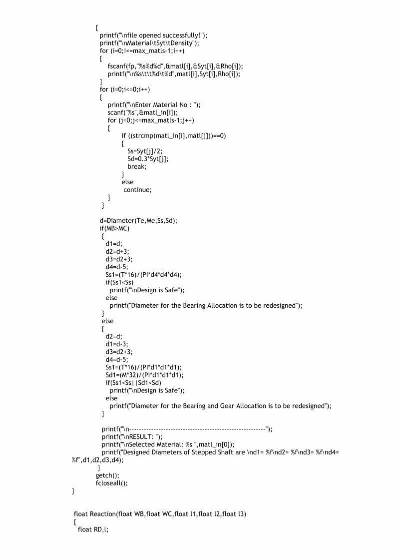
{ printf("\nfile opened successfully!"); printf("\nMaterial\tSyt\tDensity"); for (i=0;i<=max_matls-1;i++) { fscanf(fp,"%s%d%d",&matl[i],&Syt[i],&Rho[i]); printf("\n%s\t\t%d\t%d",matl[i],Syt[i],Rho[i]); } for (i=0;i<=0;i++) { printf("\nEnter Material No : "); scanf("%s",&matl_in[i]); for (j=0;j<=max_matls-1;j++) {
if ((strcmp(matl_in[i],matl[j]))==0) { Ss=Syt[j]/2; Sd=0.3*Syt[j]; break; } else continue;
} }
d=Diameter(Te,Me,Ss,Sd); if(MB>MC) { d1=d; d2=d+3; d3=d2+3; d4=d-5; Ss1=(T*16)/(PI*d4*d4*d4); if(Ss1<Ss) printf("\nDesign is Safe"); else printf("Diameter for the Bearing Allocation is to be redesigned"); } else { d2=d; d1=d-3; d3=d2+3; d4=d-5; Ss1=(T*16)/(PI*d1*d1*d1); Sd1=(M*32)/(PI*d1*d1*d1); if(Ss1<Ss||Sd1<Sd) printf("\nDesign is Safe"); else printf("Diameter for the Bearing and Gear Allocation is to be redesigned"); }
printf("\n--------------------------------------------------------"); printf("\nRESULT: "); printf("\nSelected Material: %s ",matl_in[0]); printf("Designed Diameters of Stepped Shaft are \nd1= %f\nd2= %f\nd3= %f\nd4=
%f",d1,d2,d3,d4); }getch();fcloseall();
}
float Reaction(float WB,float WC,float l1,float l2,float l3) { float RD,l;

l=l1+l2+l3; RD=(WC*(l1+l2)+(WB*l1))/l; return(RD); }
float Diameter(long Te,long Me,float Ss,float Sd) { float d1,d2,x1,x2; x1=(Te*16)/(PI*Ss); d1=pow(x1,0.3334); x2=(Me*32)/(PI*Sd); d2=pow(x2,0.3334); if(d1>=d2) return(d1); else return(d2); }
DESIGN STEPS OF SLIDING CONTACT BEARING
DATA INPUT FOR SLIDING CONTACT BEARING DESIGN :-
1) Diameter of the journal
2) Load on the journal
3) Speed of rotation
4) Type of machinery
5) Allowable temperature rise in lubricating oil if any
DESIGN STEPS FOR SLIDING CONTACT BEARIGN :-
1) Select the recommended values of the following as per the application
Range of L/d ratio Maximum bearing pressure (PMAX) Minimum bearing modulus (Z * N / P) Suitable Viscosity (Z) Range of P * V
2) Calculate the rubbing velocity V in m/min.
3) Choose suitable value for the length of the journal L, so that all the three criteria given
below are satisfied
The L/d ratio is within the recommended range. The bearing pressure is within the recommended range. P * V value within the given range.
4) Select the suitable bearing material
5) Select the suitable radial clearance C.
6) Select suitable Z * N/P depending upon the variability of load and speed.
7) Calculate the value of Z and select suitable lubricating oil.
8) Calculate the dimensionless value of the Summerfield no.
9) Calculate the coefficient of friction μ.
10) Select the suitable radial clearance C.
11) Calculate the heat generated Hg.
12) Calculate the temperature rise of the oil equating Hg to the heat dissipating capacity
Hd.
13) Calculate the oil temp. Toil & check the value within the given range.
14) Calculate minimum film thickness hmin, & select suitable surface finish for the journal
and the bushing.
15) Calculate the amount of side flow of the lubricant. This is the quantity of oil to be
supplied to the bearing to maintain the fluid flow.
OUTPUT DATA FROM THE PROGRAM :-
1) Length of bearing
2) Bearing material
3) Lubrication oil to be used
4) Quantity of oil to be supplied for maintaining the fluid film
/* Design for Sliding Contact Bearing */
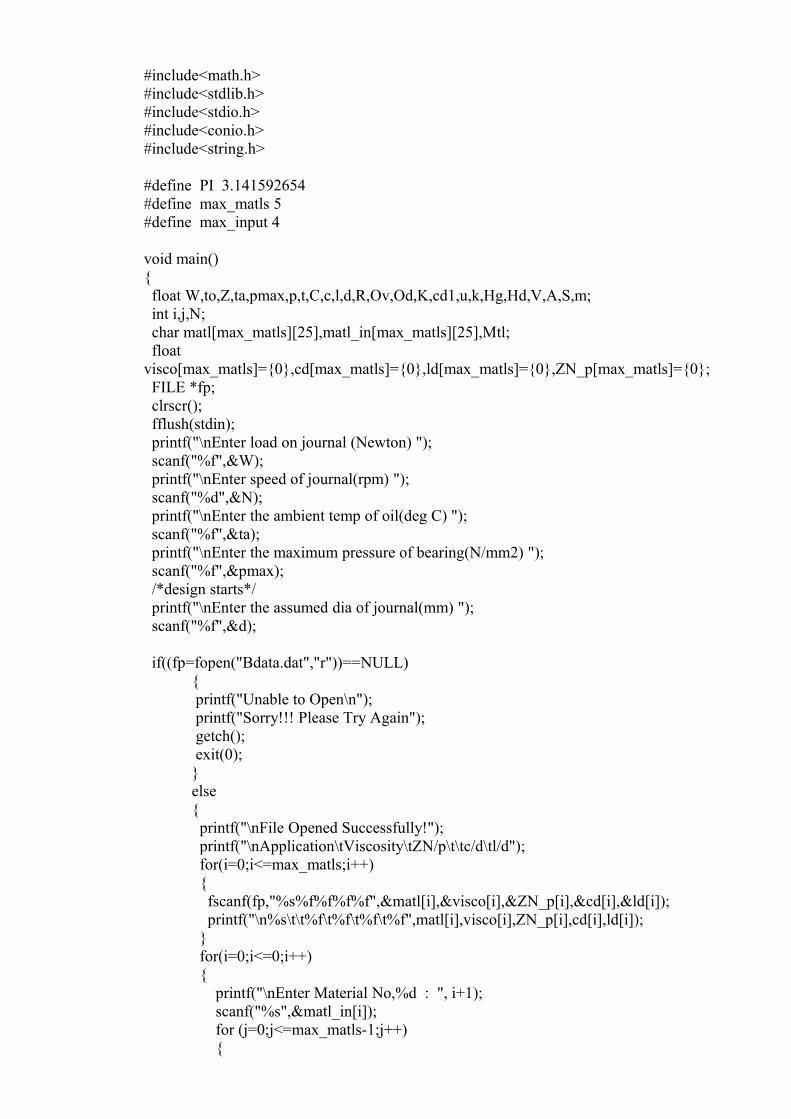
#include<math.h>#include<stdlib.h>#include<stdio.h>#include<conio.h>#include<string.h>
#define PI 3.141592654#define max_matls 5#define max_input 4
void main(){ float W,to,Z,ta,pmax,p,t,C,c,l,d,R,Ov,Od,K,cd1,u,k,Hg,Hd,V,A,S,m; int i,j,N; char matl[max_matls][25],matl_in[max_matls][25],Mtl; float visco[max_matls]={0},cd[max_matls]={0},ld[max_matls]={0},ZN_p[max_matls]={0}; FILE *fp; clrscr(); fflush(stdin); printf("\nEnter load on journal (Newton) "); scanf("%f",&W); printf("\nEnter speed of journal(rpm) "); scanf("%d",&N); printf("\nEnter the ambient temp of oil(deg C) "); scanf("%f",&ta); printf("\nEnter the maximum pressure of bearing(N/mm2) "); scanf("%f",&pmax); /*design starts*/ printf("\nEnter the assumed dia of journal(mm) "); scanf("%f",&d);
if((fp=fopen("Bdata.dat","r"))==NULL){ printf("Unable to Open\n"); printf("Sorry!!! Please Try Again"); getch(); exit(0);}else{ printf("\nFile Opened Successfully!"); printf("\nApplication\tViscosity\tZN/p\t\tc/d\tl/d"); for(i=0;i<=max_matls;i++) { fscanf(fp,"%s%f%f%f%f",&matl[i],&visco[i],&ZN_p[i],&cd[i],&ld[i]); printf("\n%s\t\t%f\t%f\t%f\t%f",matl[i],visco[i],ZN_p[i],cd[i],ld[i]); } for(i=0;i<=0;i++) { printf("\nEnter Material No,%d : ", i+1); scanf("%s",&matl_in[i]); for (j=0;j<=max_matls-1;j++) {
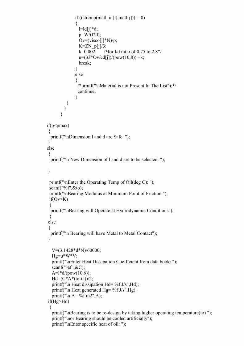
if ((strcmp(matl_in[i],matl[j]))==0) { l=ld[j]*d; p=W/(l*d); Ov=(visco[j]*N)/p; K=ZN_p[j]/3; k=0.002; /*for l/d ratio of 0.75 to 2.8*/ u=(33*Ov/cd[j])/(pow(10,8)) +k; break; } else { /*printf("\nMaterial is not Present In The List");*/ continue; }
} } }
if(p<pmax) { printf("\nDimension l and d are Safe: "); } else { printf("\n New Dimension of l and d are to be selected: ");
}
printf("\nEnter the Operating Temp of Oil(deg C): "); scanf("%f",&to); printf("\nBearing Modulus at Minimum Point of Friction "); if(Ov>K) { printf("\nBearing will Operate at Hydrodynamic Conditions"); } else { printf("\n Bearing will have Metal to Metal Contact"); }
V=(3.1428*d*N)/60000; Hg=u*W*V; printf("\nEnter Heat Dissipation Coefficient from data book: "); scanf("%f",&C); A=l*d/(pow(10,6)); Hd=(C*A*(to-ta))/2; printf("\n Heat dissipation Hd= %f J/s",Hd); printf("\n Heat generated Hg= %f J/s",Hg); printf("\n A= %f m2",A); if(Hg>Hd) { printf("\nBearing is to be re-design by taking higher operating temperature(to) "); printf("\nor Bearing should be cooled artificially"); printf("\nEnter specific heat of oil: ");
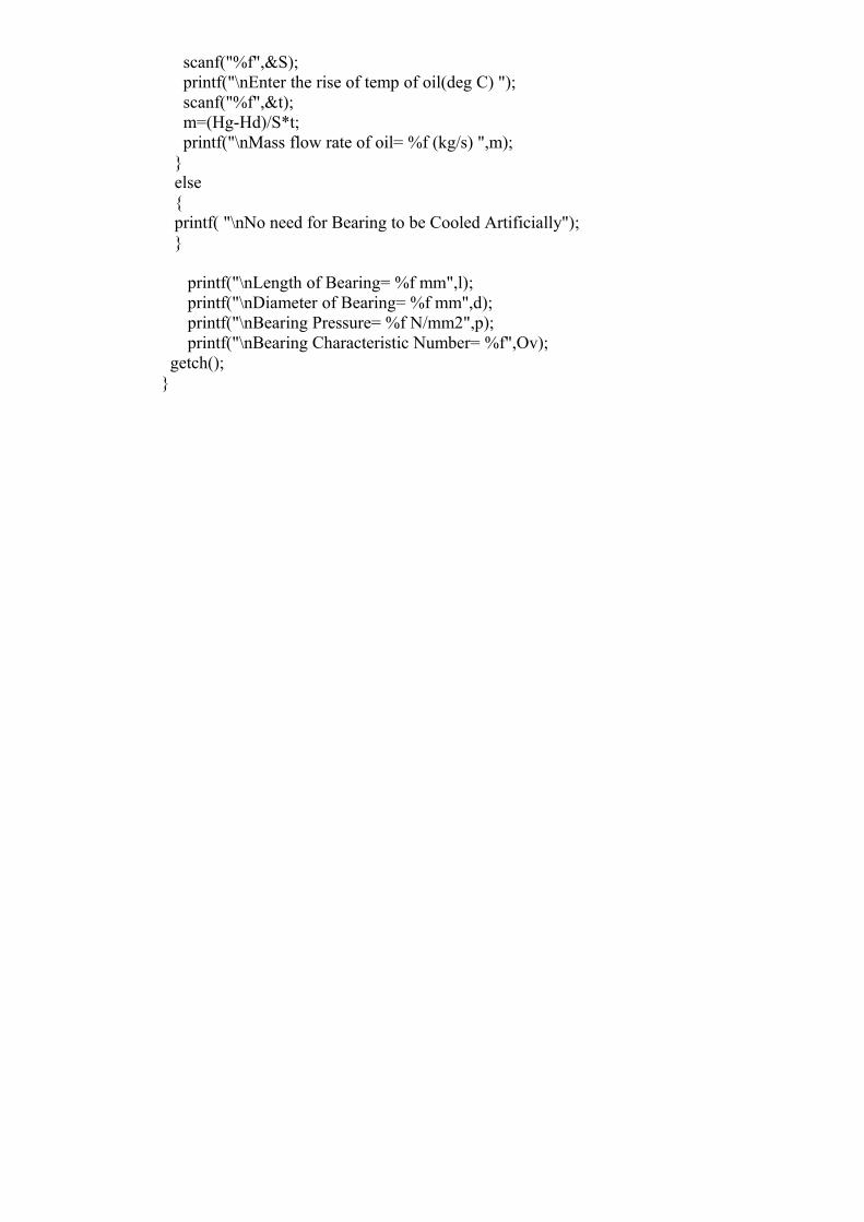
scanf("%f",&S); printf("\nEnter the rise of temp of oil(deg C) "); scanf("%f",&t); m=(Hg-Hd)/S*t; printf("\nMass flow rate of oil= %f (kg/s) ",m); } else { printf( "\nNo need for Bearing to be Cooled Artificially"); }
printf("\nLength of Bearing= %f mm",l); printf("\nDiameter of Bearing= %f mm",d); printf("\nBearing Pressure= %f N/mm2",p); printf("\nBearing Characteristic Number= %f",Ov); getch(); }
DESIGN STEPS OF FLYWHEEL
DATA INPUT FOR FLYWHEEL DESIGN :-
1) Data related to fluctuation of speed & energy
2) Material of flywheel
3) Space constraint & Type of application
DESIGN STEPS FOR FLYWHEEL :-
A) Calculate the fluctuation of energy ΔΕ from the given data.
B) Calculate the fluctuation of speed otherwise select the fluctuation of speed as per the
driven machinery & type of the driven arrangement (Ks).
C) Calculate the required moment of inertia as
ΔΕ = I * Ks * ωm2
Here,I = moment of inertiaKs = speed fluctuation coefficientωm = mean velocity in rad/sec.
# If the construction of the flywheel is rimmed then 5% of inertia is contributed by the
hub & rim, the remaining inertia is provided by the rim.
D) Calculate the mean diameter of the rim with the help of allowable surface speed (Vs)
Vs = π * Do * N
Here,N = the r.p.m. of flywheel Do = mean dia.Vs =surface speed
E) Calculate the mass of the rim
I = m * K2
Here,K = radius of gyrationm = mass of rim
F) Calculate height & width of rim as ratio of width & height is
B/H = 0.65 To 2.0
G) Decide the type of construction; cross-section of arms & number of arms
H) Calculate the centrifugal stresses, bending stresses & the resultant stresses in the rim
for the safe range by altering the value of B & H.
I) Calculate the hub diameter, hub length & arm dimensions.
OUTPUT DATA FROM THE PROGRAM :-
1) Width & height of the flywheel rim
2) Type of construction for the flywheel
3) Hub diameter & its length
4) Arm dimensions
/* Program to Design Flywheel */
#include<stdio.h>#include<math.h>#include<stdlib.h>#include<string.h>#include<conio.h>#include<dos.h>
#define PI 3.141592654#define max_matls 13#define max_input 4
void main(void){ float m,t,b,rho,FS,Syt,Sd,DE,Cs,D,Rad,k; char matl[max_matls][15],matl_in[max_matls][15]; float Rho[max_matls]={0}; int syt[max_matls]={0}; int N,i,j; FILE *fp; clrscr(); fflush(stdin);
printf("Enter The Speed of the Shaft (RPM) : "); scanf("%d",&N); /*printf("Enter the Ultimate Stress in Tension of Material Selected (N/m2) : "); scanf("%f",&Syt); printf("Enter the Density of Material Selected (kg/m3) : "); scanf("%f",&rho);*/ printf("Enter the Factor of Safty For The Material Selected : "); scanf("%f",&FS); printf("Enter the Coefficient of Fluctuation of Speed : "); scanf("%f",&Cs); printf("Enter the Fluctuation of Energy : "); scanf("%f",&DE);
if((fp=fopen("sd1.dat","r"))==NULL){ printf("Unable to Open\n"); printf("Sorry!!! Please Try Again"); getch(); exit(0);}else{ printf("File Opened Successfully!"); printf("\nMatl. \tsyt\trho"); for(i=0;i<=max_matls;i++) { fscanf(fp,"%s %d %f",&matl[i],&syt[i],&Rho[i]); printf("\n %s \t%d\t%f",matl[i],syt[i],Rho[i]); }for(i=0;i<=0;i++) { printf("\nEnter Material No,%d : ", i+1); scanf("%s",&matl_in[i]); for(j=0;j<=max_matls-1;j++) {
if((strcmp(matl_in[i],matl[j]))==0) { Syt=syt[j]; Sd=Syt*1000000/FS; D=(Sd*3600)/(Rho[j]*PI*PI*N*N); Rad=(2*PI*N)/60;
m=(4*DE)/(D*D*Rad*Rad*Cs); k=m/(2*PI*D*Rho[j]*4); t=sqrt(k); b=4*t; break; } else { /*printf("\nMaterial is not Present In The List"); break;*/ continue; }
} }}
clrscr(); printf("You have Selected the Material as %s",matl[0]); printf("\nFor the Entered Data : \nDiameter Of The Flywheel is : %f m",D); printf("\nMass of The Flywheel is : %f kg",m); printf("\nThickness of The Flywheel is : %f m",t); printf("\nWidth of The Flywheel is : %f m",b); getch();}
DESGIN PROCEDURE OF SPUR GEAR
DATA INPUT FOR SPUR GEAR DESIGN :-
1) Power to be transmitted
2) Gear ratio
3) Space availability
4) Type of application
DESGIN STEPS FOR SPUR GEAR :-
1) CALCULATE THE GEOMETRY OF THE GEAR PINION :-
A) Design power (Pd)Pd = Pr * Kl
Here,Pr = Rated PowerKl = Load Factor
B) Select the proper tooth profile
Tooth profile of the gear selected as
(a) Commonly used profile is 20o full depths.(b) For low space availability 20o stub form is used. (c) If noise level is to be kept low & there is no space constraint, 14.5o
full depth form is used.C) Select the number of teeth on pinion (Tp)
Numbers of teeth on pinion is selected for good balance in strength &
wear for hard steel
D) Calculate the Number of teeth on gear (Tg)
Gear Ratio = Tg / Tp
E) Calculate the pitch circle diameter (Dp)Assume the module of teeth as ‘m’ mm & calculate the pitch circle diameter of
pinion as follows
Dp = Tp * m
F) Calculate the pitch line velocity (Vp)
Vp = π * Dp * Np
Here, Np is the revolution of pinion
G) Calculate the tangential tooth load (Ft)
Ft = Pd / Vp
H) Select the suitable material for the pinion & the corresponding basic stress (So).
I) Select the velocity factor (Cv) Velocity factor Cv is as per
Cv = 0.40 for pinion speed up to 1000 rpm.Cv = 0.30 for pinion speed in between 1000 – 2000 rpm.Cv = 0.25 for pinion speed above 2000 rpm.
J) Takethe trial of the face width in terms of module as b = 10m
K) Calculate the modified Lewis factor (γ) as per type of tooth profile
L) Calculate the Bending strength of Gear tooth (FB) as modified Lewis equation as follows in
terms of module.
FB = S0 * Cv * b * γ * ms
M) Calculate the module m by equating tangential load FT & bending strength FB
FT = FB
N) Select the next standard module (m) available.
O) Calculate the actual value of Dp with the new module from step N
Dp = 2d + 25 for keyed pinion
Dp = d + 25 for internal pinion
Use the above equation if the shaft diameter is given otherwise
Dp = m * Tp & select Dp such that it should
have higher value.
P) Calculate the actual value of
I. Pitch line velocity (Vp)II. Velocity fact (Cv)III. Tangential tooth load (Ft )IV. Bending strength (FB)
Q) Select the material for the gear & calculate the value of (S0 * γ ) for both pinion
& gear.
R) Take the smaller value of (S0 * γ ) for calculating the face width (b).
S) Calculate face width (b) from the modified Lewis equation.
T) Calculate the face width (minimum) from standard proportion as
b = 8.5 * m
select the bigger value of face width from step S & T
2) DESIGN CHECK FOR DYNAMIC LOAD & LIMITING WEAR STRENGTH.
A) Calculate the dynamic load (Fd)
a) Find out the permissible error in profile as per the pitch line velocity.b) Decide the class of manufacturing process as the permissible error found
in step a.c) Find out the probable error in the teeth profile as per module.d) Calculate the deformation factor “C”. This depends upon the material
of the gear & pinion along with the type of teeth profile.
Deformation factor
C = a / (1 / Ep + 1 / Eg )Here,
a is constant ratio as per teeth profile as,a = 0.107 for 14.50 full depth.a = 0.107 for 20.00 full depth.a = 0.107 for 20.00 stub.Ep = Young’s modulus of PinionEg = Young’s modulus of Gear.
e) Calculate the dynamic load (Fd) as
Fd = Ft + {[21* Vp * (C * e * b + Ft)] / [21 * Vp + ( C * e * b + Ft )½
]}Here,
Ft = tangential tooth loadVp = pitch line velocityC =deformation factorE = probable error in tooth cuttingB = face widthFd = dynamic load
B) Calculate the limiting wear strength Fw :-
a) Calculate size factor
Q = 2 * Tp * Tg / (Tp + Tg ) for external gear
Q = 2 * Tp * Tg / (Tp - Tg ) for internal gear
b) Limiting wear strength is as
Fw = Dp * b * K * Q
c) Calculate the load stress factor by equating Fw & Fd
d) Select the suitable hardness as load stress factor
C) Calculate the endurance strength Fen
a) Select the endurance strength as per the material of gear & pinion &
hartness.
b) Calculate the endurance strength Fen
Fen = Seb * b * y * m
D) Check that endurance strength should be more than the dynamic load. If not
then increase the
face width with in the allowable range i.e.
8.5 * m < b < 12.5 * m
Other wise change the material & the material & the hear treatment.
3) DESIGN OF THE GEAR BLANK
A) Construction of gear blank is of three types as
i) Solid construction if
Dp < or = 15 * m + 60 mm
ii) Web construction if
Dp < or = 24 * m + 80 mm
In this case thickness of web is as
W = 1.5 * m + 3
iii) Arms construction if
Dp >24 * m + 80 mm
B) Rim thickness (T) is given as
T = 1.5 * m to 2.0 * m
C) Hub length & hub diameter is calculated as per the type of service & material of
construction.
OUTPUT DATA FROM THE PROGRAM :-
1) Tooth profile
2) Number of teeth on gear
3) Pitch circle diameter of gear & pinion
4) Material of gear & pinion & hardness
5) Face width, module
6) Construction of gear blank.
/* Programme to Design Spur Gear */
#include<stdio.h>#include<math.h>#include<stdlib.h>#include<string.h>#include<conio.h>#include<dos.h>
#define PI 3.141592654#define max_matls 13
#define max_input 4
main(){ float Yp,Yg,P,VR,fop,fog,Tp,Tg,b,V,Cs,fes,fe,Ep,Eg,Cv,Wt,Ws,Wd,Ww; float fp,fg,phi,Ks,C,Wi,K,e,Y,Q,m,Dp,Dg,temp; int Np; clrscr(); printf("\nEnter The Speed of the pinion (RPM) : "); scanf("%d",&Np); printf("\nEnter The Power to be Transmitted : "); scanf("%f",&P); printf("\nEnter The Service factor for the Gear (From the Databook) : "); scanf("%f",&Cs); /*printf("\nEnter The Speed of the Gear : "); scanf("%f",&V);*/ printf("\nEnter The number of Teeth On Gear : "); scanf("%f",&Tg); printf("\nEnter The number of Teeth On Pinion : "); scanf("%f",&Tp); Yp=0.154-(0.912/Tp); Yg=0.154-(0.912/Tg); printf("\nAllowable Static Streses for Gear : "); scanf("%f",&fog); printf("\nAllowable Static Streses for Pinion : "); scanf("%f",&fop); clrscr(); fp=fog*Yp; fg=fog*Yg;
V=(PI*Tp*Np)/60; Wt=(P*Cs)/V; Cv=4.5/(4.5+V); if(fp<fg) { printf("\nDesign will be based on the Pinion");
temp=(Wt/(fop*Cv*14*PI*Yp)); printf("Yp=%f",Yp); printf("V=%f",V); printf("Temp=%f",temp); m=pow(temp,0.333334); printf("The Module Is = %f",m); Y=Yp; b=14*m; Dp=m*Tp; Dg=m*Tg; printf("\nThe module of gear & Pinion: %f",m); printf("\nThe Diameter of Gear: %f",Dg); printf("\nThe Diameter of Pinion: %f",Dp); } /*else { printf("Design will be based on the Gear"); m=sqrt(Wt/(fog*Cv*14*PI*Yg)); Y=Yg; b=14*m; Dp=m*Tp; Dg=m*Tg; printf("\nThe module of gear & pinion: %f",m); printf("\nThe Diameter of Gear: %f",Dg); printf("\nThe Diameter of Pinion: %f",Dp); } printf("\nthe Face Width Of The Gear & Pinion is : %f",b);
printf("\nCheking these Dimensoin for Wear and Endurence Strength"); */
/* Check for wear & endurance strength*//* printf("Enter the Modulus of Elasticity Of the Gear"); scanf("%f",&Eg); printf("Enter the Modulus of Elasticity Of the Pinion"); scanf("%f",&Ep); printf("Enter the Pressure angle for the Gear/Pinion"); scanf("%f",&phi); printf("Enter the Surface Endurence Limit For the Gear/Pinion "); scanf("%f",&fes); printf("Enter the Flexural Endurence Limit For the Gear/Pinion "); scanf("%f",&fe); printf("Enter the Form factor For Given Gear/Pinion (from the data book) "); scanf("%f",&K); printf("Enter the Tooth Error Action For Given Gear/Pinion (in mm) (from the data book) "); scanf("%f",&e);
VR=Tg/Tp; Q=(2*VR)/(VR+1); */ /*Q is ratio factor*/ Ks=((fes*fes*sin(phi))/1.4)*((Eg+Ep)/(Ep*Eg)); C=(K*e)/((1/Ep)+(1/Eg)); Wd=Wt+((21*V*(b*C+Wt)))/((21*V)+(sqrt(b*C+Wt))); Ws=fe*b*PI*m*Y; Ww=Dp*b*Q*Ks; if(Ws>Wd&&Ww>Wd) printf("The Design is safe"); else printf("Gear is to be Redesigned"); getch(); }
DESIGN STEPS OF RIGID FLANGE COUPLING
DATA INPUT FOR RIGID FLANGE COUPLING DESIGN :-
1) Shaft Diameter to be connected
2) Material of shaft
3) Fitment of bolts
DESIGN STEPS FOR RIGID FLANGE COUPLING :-
1) CALCULATION FOR VAROUS DIMENSIONS OF COUPLING
A) Calculate dimensions of hub dims meter & hub length of the coupling
1) Hub diameter of coupling (dh) Dh= ( 1.5*D)+25( here D is the di. Of shaft)
3) Hub length of coupling (Lh)Lh = (1.25*D)+20
B) Calculate the number of bolts requires to connect the coupling flanges (N)N=(0.02*D)+3
C) Calculate the bolt diameter (Db)Db= 0.5*D/ (N) 1/2
# Select the nearest higher size available for the bolt diameter.
D) Calculate flange thickness (Tr) Tf = Db
E) Calculate the width of flange protector (B) B= 2.5 * Db
F) Calculate pitch circle diameter (Dp) Dp = (2* D) = 50
G) Calculate the outer diameter of coupling flange (Do)Do = ( 2.5 * D) + 75
2) STRENGTH CHECK
A) Calculate the torque capacity of the shaft
a) Find out ultimate strength ( Sut) & yield strength (Syt) of the shaft
material
b) calculate the allowable shear stress in the shaft stress τall = 0.18*Sut
τall = 0.30*Syt
Take the lower value of allowable shear stress
c) Modify the value of allowable shear for the consideration of keyway as τall = 0.75* ( Lower value of τall from step b )
d) Torque the bolts for shear failure T= 16*D3* (Take the value of τall from the step c)
B) Check the bolts for shear failure
a) Calculate the shear stress in the bolt as
τbolt =T*B/ (π*Dp*N) ( T is the torque capacity of the
bolt )
b) Check criteria for crushing failure
τbolt< πall (τbolt is the allowable shear stress from step
2.A.c.)
C) Check the bolts for crushing failure
a) Calculate the crushing stress in the bolt
бer=4*T/( Db * Tf *N*Dp ) ( T is the torque capacity of
the bolt)
b) calculate the allowable crushing stress in the bolt
(бer) all = 2* τall
c) check criteria for safe design
бer < (бer) all
D) Check the flange for shear failure
a) Calculate the shear stress in flange of the coupling
τ = 2 * T/ (π * Tf * Dh * Db )
b) Select the service factor depending upon type of driven & driving
machine
c) Calculate the allowable shear stress in the flange of the coupling
τ = Sut / service factor
d) Check criteria for safe design
τ = or < τall
OUTPUT DATA FROM THE PROGRAM :-
1) Hub diameter & it’s length
2) Bolt diameter & number of bolts, pitch circle diameter
3) Flange thickness, width of flange protector
4) Outer diameter of coupling flange
5) Material of coupling & bolts
/* Program to Design Rigid Flange Coupling */
#include<math.h>#include<graphics.h>#include<stdlib.h>
#include<stdio.h>#include<conio.h>
#define PI 3.141592654#define max_matls 5#define max_input 4
void main(){ float T,fs,fcb,fsf,fsf1,fsf2,d,D,L,l,w,t,fsk,fck,fsk1,fck1,tf; float D1,d1,D2,i1,fsb,tp; int n,j,i; char matl[max_matls][25],matl_in[max_matls][25],Mtl; float SS[max_matls]={0},CS[max_matls]={0}; FILE *fp; clrscr(); fflush(stdin); clrscr(); printf("\nEnter value of torque (Newton-mm) "); scanf("%f",&T);
/*printf("\nEnter value of shear stress for shaft (Newton-mm2) "); scanf("%f",&fs); printf("\nEnter value of shear stress for flange material (Newton-mm2) "); scanf("%f",&fsf);*/
if((fp=fopen("CPdata.dat","r"))==NULL){ printf("Unable to Open\n"); printf("Sorry!!! Please Try Again"); getch(); exit(0);}else{ printf("\nFile Opened Successfully!"); printf("\nMaterial\tShear Stress\tCrushing Stress"); for(i=0;i<=max_matls-1;i++) { fscanf(fp,"%s%f%f",&matl[i],&SS[i],&CS[i]); printf("\n%s\t\t%f\t%f",matl[i],SS[i],CS[i]); } for(i=0;i<=3;i++) { if(i==0)
printf("\nEnter Material for Shaft : "); else { if(i==1)
printf("\nEnter Material for Flange Coupling
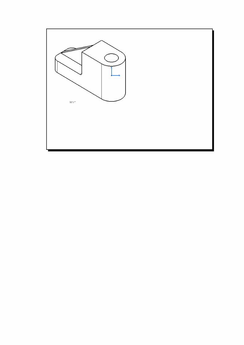
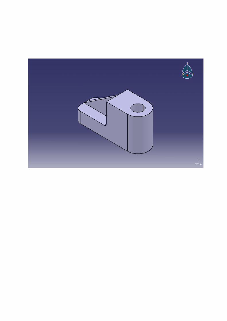
EXPERIMENT N o. 10
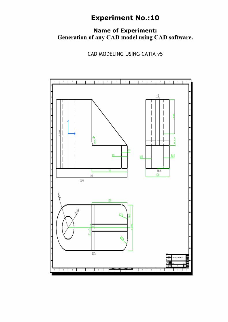
Experiment No.:10
Name of Experiment:Generation of any CAD model using CAD software.
CAD MODELING USING CATIA v5