Embed Size (px)
Citation preview
International Journal on Recent and Innovation Trends in Computing and Communication ISSN: 2321-8169 Volume: 3 Issue: 7 4994 - 5000
_______________________________________________________________________________________________
4994
IJRITCC | July 2015, Available @ http://www.ijritcc.org
_______________________________________________________________________________________
Design And Implementation Of Electrical Transmission Line Monitoring And
Controlling System
Trupti Sudhakar Somkuwar
P.G. Student, Department Of Computer Technology
Priyadarshini College Of Engineering
Nagpur, India
Mr. Mahesh G. Panjwani
Assistant Professor, Department Of Computer Technology
Priyadarshini College Of Engineering
Nagpur, India
Dr. Prakash S. Prasad
Associate Professor, Department Of Computer Technology
Priyadarshni College Of Engineering
Nagpur, India
Mr. N . A. Ghodichor
Assistant Professor, Department Of Computer Technology
Priyadarshini College Of Engineering
Nagpur, India
Abstract— As the electric transmission line is spread widely at long distance location is become difficult to monitor, control the power supply in
the transmission line. Physical inspection at every location and troubleshooting is not feasible. Same problem is still facing at traffic monitor and
control units as every square which are currently controlled manually by operator. Wireless Sensor Network (WSN) provides access over remote
location with centralized monitoring and controlling on different channels so it can be utilized for electric transmission line monitoring. While
the WSNs are capable of cost efficient monitoring over vast geo-locations, several technical challenges exist. To overcome these problems in
regional areas proposed system is designed to monitor and control the electric transmission line using WSN. Here we are building a wireless
node which can centrally monitor and controlled through base station or the wireless cluster head. A centralized server will be responsible to see
the electric poll status and control the poll activities to enable or disable power in particular area. As it is not feasible to monitor the central
server full time, So the proposed system is designed to have emergency alert system for remote user with the help of a GSM modem will be
connected to the central server which will send the emergency alert SMS to administrator and user.
Keywords- overhead transmission line,electric distribution system,smart grid,wireless sensor network
__________________________________________________*****_________________________________________________
I. INTRODUCTION
For our current society electricity is important, and in order to
properly maintain and develop power distribution system, it is
needed to understand and monitor the system behavior. The
system behavior i.e. Power grid constitute the electricity
generation system, electric power transmission system, and
electric distribution system. Transmission line monitoring is
very significant issue to ensure useful and reliable
transmission of electricity.
For transmission of electric power high voltage transmission
line are responsible. Their sag and electric current are
important parameter for transmission line monitoring. Internet
of thing (IOT) used in smart grid is the predictable result of
the growth of information communication technology to a
certain stage. It will be capable of effective integrate of the
infrastructure resources in communications and electrical
control system, create the information and communication
services manage for electrical power system , increase the
level of power system information, and to get better the
utilization efficiency of infrastructure in the existing power
system. since Internet Of Thing technology has been used in
smart grid, the important technical support for the generation,
transmission, substation, distribution, electricity and other
aspects of power grid can be efficiently provided. Smart grid is
totally enclosed with an electrical system. For the developing
countries, smart grid technology has great importance. Smart
grid involves the complete electrical network and regional
electrical network and a sub network like local utility
transmission grid and distribution grid.
Electricity in a remote location is carried by a simple
distribution grid linking a central generator to homes. In India
during the process of electricity transmission and electricity
distribution losses are occurred at very large amount and
change between 30 to 45%. Low metering efficiency, theft and
pilferage this are the main reason for electricity losses in India
.for electricity and security of smart gird, intelligent power line
monitoring is important part. For that large number of
sensors is required to find out the power system fault in a
distributed network. By including the number of sensor nodes,
position of accuracy can be easily found. WSN are generally
used to detect and locate the fault. Our goal and contribute in
this work is to provide an efficient electrical distribution
line. Transmission lines are consistent with each others, It
can be utilized for electric transmission line monitoring,
controlling then it turn into association of transmission
network. Wireless sensor network (WSN) offer access over
International Journal on Recent and Innovation Trends in Computing and Communication ISSN: 2321-8169 Volume: 3 Issue: 7 4994 - 5000
_______________________________________________________________________________________________
4995
IJRITCC | July 2015, Available @ http://www.ijritcc.org
_______________________________________________________________________________________
remote areas with centralized monitoring and controlling on
different channels so real time power flows.
Increase in demand of electricity for entire applications in any
country, need to create exclusive of fail with advanced
monitoring system. Consider a condition when there is power
failure at particular area then anybody from that area has to
inform electric support office and then and then only official
person come to know about the failure of power. On other
hand if due to any reason if officials wants to shut down power
at particular area there is no direct remote control over the
supply hence linemen has to go and manually shutdown the
system.
These both the issues are very critical and it is expected
minimum time support from the support system. Implementing
this will reduce more time and also officials can give better
supports to their customers. Considering all these problem we
are trying to design and developing the remote electric
transmission line monitoring and control system where
autonomous system fixed at every electric pole will look at the
power supply state and control its supply on command. Along
with the pole fixed device there are base stations which will
monitor pole status by communicating with pole device
through wireless medium.
II. RELATED WORK
“Wireless Network Design for Transmission Line
Monitoring in Smart Grid” Benazir Fateh, Student
Member, IEEE, ManimaranGovindarasu, Senior Member,
IEEE, and VenkataramanaAjjarapu, Fellow, IEEE.
In this paper, they develop a real-time situational awareness
framework for the electrical transmission power grid using
Wireless Sensor Network (WSN). While WSNs are capable of
cost efficient monitoring over vast geographical areas, several
technical challenges exist. The low power, low data rate
devices cause bandwidth and latency bottlenecks. In this
paper, their objective is to design a wireless network capable
of real-time delivery of physical measurements for ideal
preventive or corrective control action. For network design,
they formulate an optimization problem with the objective of
minimizing the installation and operational costs while
satisfying the end-to-end latency and bandwidth constraints of
the data flows. They study a hybrid hierarchical network
architecture composed of a combination of wired, wireless and
cellular technologies that can guarantee low cost real-time data
monitoring. They formulate a placement problem to find the
optimal location of cellular enabled transmission towers.
Further, they present evaluation results of the optimization
solution for diverse scenarios. Their formulation is generic and
addresses real world scenarios with asymmetric sensor data
generation, unreliable wireless link behavior, non-uniform
cellular coverage, etc. Their analysis shows that a transmission
line monitoring framework using WSN is indeed feasible
using available technologies. Their results show that wireless
link bandwidth can be a limiting factor for cost optimization .
“An efficient monitoring of substations using
microcontroller based monitoring system” V.
Thiyagarajan& T.G. Palanivel 1Assistant professor,
PeriyarManiammai University 2Principal, Kamban
Engineering College, Thiruvannamalai.
The paper proposes an innovative design to develop a system
based on AVR micro controller that is used for monitoring the
voltage, current and temperature of a distribution transformer
in a substation and to protect the system from the rise in
mentioned parameters. Providing the protection to the
distribution transformer can be accomplished by shutting
down the entire unit with the aid of the Radio frequency
Communication. Moreover the system displays the same on a
PC at the main station which is at a remote place. Furthermore
it is capable of recognizing the break downs caused due to
overload, high temperature and over voltage. The design
generally consists of two units, one in the substation unit,
called as transmitter and display unit, and another in the Main
station called as controlling unit. The transmitter and the
display units in the substation is where the voltage, current and
temperature are monitored continuously by AVR
microcontroller and is displayed through the display unit. The
controlling unit in the main station by means of a PC and a RF
receiver receives the RF signals that are transmitted by the
Transmitter unit and reacts in accordance to the received
signal. In general, the proposed design is developed for the
user to easily recognize the distribution transformer that is
suffered by any open or short circuit and rise in temperatures.
The ultimate objective is to monitor the electrical parameters
continuously and hence to guard the burning of distribution
transformer or power transformer due to the constraints such
as overload, over temperature and input high voltage. If any of
these values increases beyond the limit then the entire unit is
shut down by the designed controlling unit.
“Smart grid (WAMS) for transmission line through
GSM”.Engr. Muhammad Junaid, Engr. Shakeel Ahmad,
and Engr. QaziWaqar Ali, department of electrical
engineering, sarhad university of science & it Peshawar
Pakistan.
Modern grid is the most complex man-made monitoring
system, which is a wide-area monitoring system (WAMS).
Next-generation smart grid will play a crucial role which will
provide time synchronization of the data, the electric power
system status (WAMS), protection and control. WAMS will
provide safe and efficient energy transfers they will as reliable
and optimize the management of the grid. Fuses are used more
in power supply, transmission lines and associated equipment.
As a general rule increased Uses of fuses can be attributed to
the low-cost, simple to maintain and reliable protection.
Application of fuse is one of the main areas in the entire
conservation plan and other significant protection coordination
unit used in smart grids. This paper attempts to review the
current status of the fuse according to its rated voltage and to
improve smart grid dynamic response based on real-time
monitoring system for high voltage fuse blown up Indicators,
second is earthling fault .
International Journal on Recent and Innovation Trends in Computing and Communication ISSN: 2321-8169 Volume: 3 Issue: 7 4994 - 5000
_______________________________________________________________________________________________
4996
IJRITCC | July 2015, Available @ http://www.ijritcc.org
_______________________________________________________________________________________
Indicator and the third is bus bar temperature rise indicator.
Furthermore dynamic protection mode is discussed and to
provide more optional applications in the smart grid to provide
high-voltage fuses blown up indicators, earthlings fault
indicator and bus bar temperature indicator. They use GSM
technology for monitoring indication.
III. PROPOSED SYSTEM
Increase in demand of electricity for entire applications in any
country, need to produce consistently with advanced
monitoring system. Consider a condition when there is power
failure at particular area then anybody from that area has to
inform electric support office and then and then only official
person come to know about the failure of power. On other
hand if due to any reason if officials wants to shut down power
at particular area there is no direct remote control over the
supply hence linemen has to go and manually shutdown the
system.
These both the issues are very critical and it is
expected minimum time support from the support system.
Implementing this will reduce more time and also officials can
give better supports to their customers. Considering all these
problem we are trying to design and developing the remote
electric transmission line monitoring and control system where
autonomous system fixed at every electric pole will look at the
power supply state and control its supply on command. Along
with the pole fixed device there are base stations which will
monitor pole status by communicating with pole device
through wireless medium.
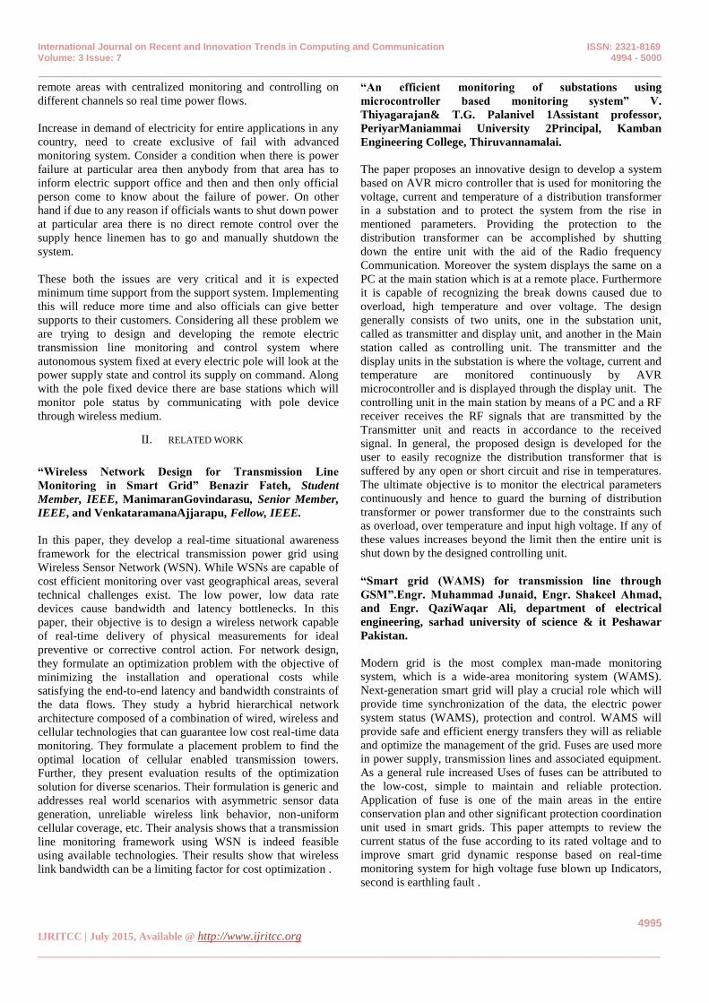
Wireless Communication
Monitoring Room
Transmission Controller
GSM Modem
RF Receiver Module
SMS to technician or Lineman
Fig : Propose system
Above figure shows the detailed working of proposed system
where it shows the proposed wireless autonomous node at
every electric pole and which are directly communicating with
the base station over wireless link. This wireless
communication is bi-directional and on demand data transfer
will be done and not continuous data transmission hence it will
save more energy and increase node life. If any node detected
failure in power supply it will send some pre-defined code
along with pole identity to base station and automatically
software will show the failed pole location on mapand detailed
information about pole. After getting the pole details system
will fetch the contact number of the linemen to whom pole
maintenance of failed node is assigned and then inform
linemen to have look over the problem if possible.
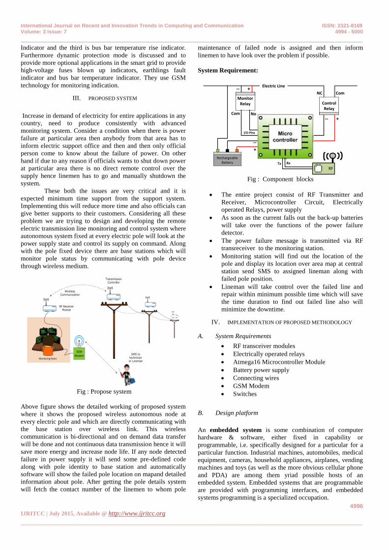
System Requirement:
Control Relay
Monitor Relay
+--
ComNC+--
Com No
I/O Pins
Rechargeable Battery
+
--
RFRxTx
Electric Line
Fig : Component blocks
The entire project consist of RF Transmitter and
Receiver, Microcontroller Circuit, Electrically
operated Relays, power supply
As soon as the current falls out the back-up batteries
will take over the functions of the power failure
detector.
The power failure message is transmitted via RF
transreceiver to the monitoring station.
Monitoring station will find out the location of the
pole and display its location over area map at central
station send SMS to assigned lineman along with
failed pole position.
Lineman will take control over the failed line and
repair within minimum possible time which will save
the time duration to find out failed line also will
minimize the downtime.
IV. IMPLEMENTATION OF PROPOSED METHODOLOGY
A. System Requirements
RF transceiver modules
Electrically operated relays
Atmega16 Microcontroller Module
Battery power supply
Connecting wires
GSM Modem
Switches
B. Design platform
An embedded system is some combination of computer
hardware & software, either fixed in capability or
programmable, i.e. specifically designed for a particular for a
particular function. Industrial machines, automobiles, medical
equipment, cameras, household appliances, airplanes, vending
machines and toys (as well as the more obvious cellular phone
and PDA) are among them yriad possible hosts of an
embedded system. Embedded systems that are programmable
are provided with programming interfaces, and embedded
systems programming is a specialized occupation.

International Journal on Recent and Innovation Trends in Computing and Communication ISSN: 2321-8169 Volume: 3 Issue: 7 4994 - 5000
_______________________________________________________________________________________________
4997
IJRITCC | July 2015, Available @ http://www.ijritcc.org
_______________________________________________________________________________________
Microsoft Visual Studio 2010 is an integrated development
environment (IDE) from Microsoft. It is used to develop
computer programs for Microsoft Windows, as well as web
sites, web applications and web services. Visual Studio uses
Microsoft software development platforms such as Windows
API, Windows Forms, Windows Presentation Foundation,
Windows Store and Microsoft Silver light. It can produce both
native code and managed code.
C. Base station
Fig :base station
USB to TTL module having FT232 IC to convert
microcontroller signals in to serial format. USB connector
provides connection between FT232 serial to USB convertor
board and USB port of computer system
FT232 acts as transition state between USB and
TTL/CMOS voltage levels thus allowing data to be read/write
through USB port. It helps to interface USB or serial port
device with module supporting UART. USB convertor
interface PCs or laptop with UART(TTL/CMOS logic)
supporting module/devices like microcontroller, Wi-Fi
module, GPS(global positioning system) module, GSM(global
system for mobiles)module, RFID(radio frequency
identification)and finger print scanner module. FT232 IC is the
one which convert TTL logic to USB logic so that devices
works on TTL logic can share the data with devices connected
through USB cables.
USB to TTL module driver will let the
application access it data using COM port. As the system is
connected to the USB 2 TTL module this module will then let
the application access its data using COM port. COM port is a
logical hardware access medium. COM (communication port)
is the original, yet still common, name of the serial port
interface on IBM PC-compatible computers. It might refer not
only to physical ports, but also to virtual Ports, such as ports
created by Bluetooth or USB –to-serial adapters.COM ports
are interfaced by an integrated circuit such as 16550 UART.
Programming language provides classes to read
from or write to data on COM port. Proposed system is using
“Serial Port” Class from .Net base classes
D. RF module
This CC2500 RF module is used for communication purpose.
And following are some important features of RF:
This RF CC250 transreceiver module is easy to use.
It Allows configuration of 255 Device IDs.
It Allows configuration of 255 Channel IDs.
It communicates in peer to peer mode.
It supports broadcast mode.
There is No need to configure at restart.
Quick Response Time.
It has Low Power Consumption.
E. Interfacing with microcontroller
It first Wait for some time (say 300 millisecond).
Then Initialize USART of microcontroller. Initial
baud rate should be 9600.
Configure CC module for its own SELF ID &
CHANNEL ID
Also Configure CC module for baud Rate (if
required). Default Baud rate is 9600.
Then Transmit data after RID (receiver id). Here data
can be a single Byte or packet of many bytes (max
packet length is 64).
F. Configuring self ID and channel ID
By sending the string using UART port microcontroller can
communicate with CC2500 module i. e
.„< „Part of protocol (less than) ,
„1‟ Self id,
„2‟ Channel id,
„>‟ Part of protocol.
G. Google map API
Google provide MAP API for developing application
to use Google Earth.
It is a Predefined function
Need to pass parameter to for map view Like,
Longitude, Latitude, Map type, Zoom Level, Label
etc.
To use Google script, we have to need to set the
parameters like longitude ,latitude, zoom level, map
type, map types shows map satellite and hybrid we
have to select the one out of this three parameters.
CC2500
+-
TxRxTx Rx
+-
FT 232
USB 2 TTL
International Journal on Recent and Innovation Trends in Computing and Communication ISSN: 2321-8169 Volume: 3 Issue: 7 4994 - 5000
_______________________________________________________________________________________________
4998
IJRITCC | July 2015, Available @ http://www.ijritcc.org
_______________________________________________________________________________________
Send the request to Google. And after that it shows
map view in the image format.
Thus by doing this we can found out the pole location
on MAP.
V. RESULT ANALYSIS
Overhead transmission lines are vulnerable to weather,
common weather component like smokes, fumes, rainfalls,
snowfalls, winds and heavy storms, humidity, line and air
temperature, all this things affect a lot, therefore, the damages
occurred in power transmission line and due to this type of
obstacle power line failure is occurred at any area. For this
purpose we need an advance monitoring system.
Transmission line is important to measure the use of power
line capacity. Electric current and line position are two
important parameters to measure the transmission line. The
aim of this project is to monitor and control the line position
at any area using the concept of electrical distribution line.
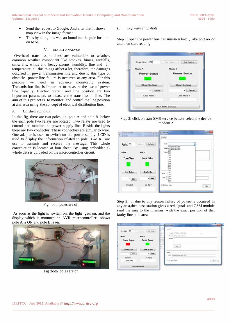
A. Hardware photos
In this fig, there are two poles, i.e. pole A and pole B. below
the each pole two relays are located. Two relays are used to
control and monitor the power supply line. Beside the lights
there are two connector. These connectors are similar to wire.
One adapter is used to switch on the power supply. LCD is
used to display the information related to pole. Two RF are
use to transmit and receive the message. This whole
construction is located at fom sheet. By using embedded C
whole data is uploaded on the microcontroller circuit.
Fig : both poles are off
As soon as the light is switch on, the light gets on, and the
display which is mounted on AVR microcontroller shows
pole A is ON and pole B is on.
Fig :both poles are on
B. Software snapshots
Step 1: open the power line transmission box ,Take port no 22
and then start reading
Step 2: click on start SMS service button select the device
modem 2
Step 3: if due to any reason failure of power is occurred in
any area,then base station gives a red signal and GSM module
send the msg to the lineman with the exact position of that
faulty line pole area
International Journal on Recent and Innovation Trends in Computing and Communication ISSN: 2321-8169 Volume: 3 Issue: 7 4994 - 5000
_______________________________________________________________________________________________
4999
IJRITCC | July 2015, Available @ http://www.ijritcc.org
_______________________________________________________________________________________
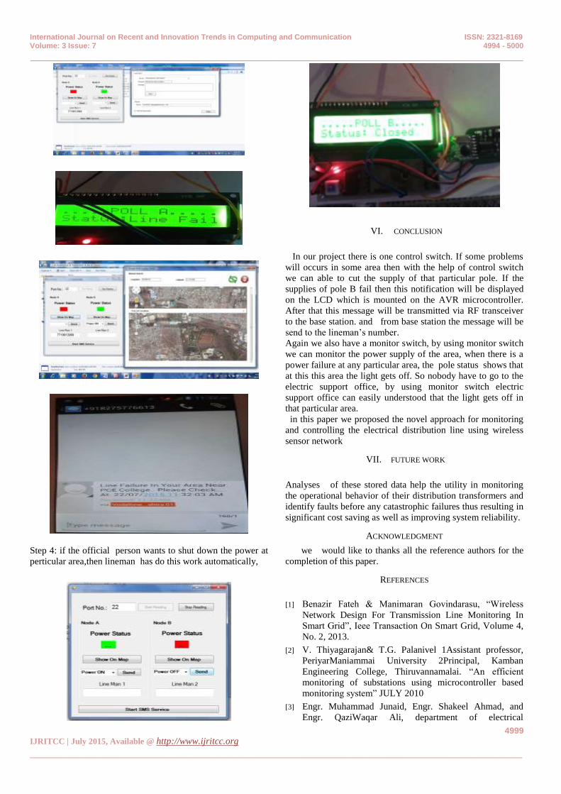
Step 4: if the official person wants to shut down the power at
perticular area,then lineman has do this work automatically,
VI. CONCLUSION
In our project there is one control switch. If some problems
will occurs in some area then with the help of control switch
we can able to cut the supply of that particular pole. If the
supplies of pole B fail then this notification will be displayed
on the LCD which is mounted on the AVR microcontroller.
After that this message will be transmitted via RF transceiver
to the base station. and from base station the message will be
send to the lineman‟s number.
Again we also have a monitor switch, by using monitor switch
we can monitor the power supply of the area, when there is a
power failure at any particular area, the pole status shows that
at this this area the light gets off. So nobody have to go to the
electric support office, by using monitor switch electric
support office can easily understood that the light gets off in
that particular area.
in this paper we proposed the novel approach for monitoring
and controlling the electrical distribution line using wireless
sensor network
VII. FUTURE WORK
Analyses of these stored data help the utility in monitoring
the operational behavior of their distribution transformers and
identify faults before any catastrophic failures thus resulting in
significant cost saving as well as improving system reliability.
ACKNOWLEDGMENT
we would like to thanks all the reference authors for the
completion of this paper.
REFERENCES
[1] Benazir Fateh & Manimaran Govindarasu, “Wireless
Network Design For Transmission Line Monitoring In
Smart Grid”, Ieee Transaction On Smart Grid, Volume 4,
No. 2, 2013.
[2] V. Thiyagarajan& T.G. Palanivel 1Assistant professor,
PeriyarManiammai University 2Principal, Kamban
Engineering College, Thiruvannamalai. “An efficient
monitoring of substations using microcontroller based
monitoring system” JULY 2010
[3] Engr. Muhammad Junaid, Engr. Shakeel Ahmad, and
Engr. QaziWaqar Ali, department of electrical
International Journal on Recent and Innovation Trends in Computing and Communication ISSN: 2321-8169 Volume: 3 Issue: 7 4994 - 5000
_______________________________________________________________________________________________
5000
IJRITCC | July 2015, Available @ http://www.ijritcc.org
_______________________________________________________________________________________
engineering, sarhad university of science & it Peshawar
Pakistan. “Smart grid (WAMS) for transmission line
through GSM”. April 2013.
[4] Ouannes, I. ; Nickel, P. ; Dostert, K. ,"Cell-Wise
Monitoring Of Lithium-Ion Batteries For Automotive
Traction Applications By Using Power Line
Communication: Battery Modeling And Channel
Characterization", 18th Ieee International Symposium On
Power Line Communications And Its Applications (Isplc),
2014.
[5] Patrick R. Casey,& Nabih Jaber “Design And
Implementation Of Cross-Platform Sensor Network For
Smart Grid Transmission Line Monitoring‟‟ieee2011
[6] Yujin Lim, Hak-Man Kim And Sanggil Kang, “A Design
Of Wireless Sensor Networks For A Power Quality
Monitoring System” , Sensors 2010
[7] Sun X. Lui, K.S ,Wong, K.K.Y. Lee W.K., Hou, Y.
Huang, Q. Pong, P.W.T., "Novel Application Of
Magneto Resistive Sensors For High-Voltage
Transmission-Line Monitoring", Ieee Transactions On
Magnetics, 2011.
[8] Iu Hua,Zhang Junguo,Lin Fantao “ Internet Of Things
Technology And Its Applications In Smart Grid‟‟vol
12,No2,2014
[9] Devidas, A.R. Ramesh, M.V. , “Wireless Smart Grid
Design For Monitoring And Optimizing Electric
Transmission In India”, Fourth International Conference
On Sensor Technologies And Applications
(Sensorcomm),Ieee 2010.
[10] Zhai Zi-Nan And Gui Wei-Feng, “Research On
Monitoring Power System Faults By Wireless Sensor
Network”, Research On Monitoring Power System Faults
By Wireless Sensor Network, 2010
[11] Qinghai Ou, Yan Zhen, Xiangzhen Li, Yiying Zhang,
Lingkang Zeng, “Application Of Internet Of Things In
Smart Grid Power Transmission”, International
Conference On Mobile, Ubiquitous, And Intelligent
Computing, 2012
[12] Li Li,Hu Xiaoguang,Chen Ke& He Ketai “ The
Application Of Wi-Fi Based Wireless Sensor Network In
Internet Of Things And Smart Grid‟‟ieee2011
[13] Peter R. Baen “ power line carrier systems for electric
heat tracing control and monitoring” IEEE transaction of
industry applications,Vol 24,No.3,may/june 1998
[14] J.C.B. Mello, D.O. Figueiredo, R. M.
Jacobsen“development of a real-time monitoring system
for controllin tensioning guy wires in transmission
line”2010 IEEE
[15] Vehbi C. Gungor, Bin Lu,“opportunities and challenges of
wireless sensor networks in smart grid” IEEE transaction
on industrial electronics,vol 57,no 10,october 2010
BIBLIOGRAPHY
Trupti S. Somkuwar received undergraduate degree
in electronics & telecommunication engineering in 2013. She is
currently student of M.E. in wireless communication and computing
branch at priyadarshini college of engineering.
Mr. M. G. Panjwani He has obtained B.TECH in Computer Science Engineering in the
year of 2006 from ACET, Nagpur and M.TECH in Embedded
System Computing in the year 2010 from GHRCE, Nagpur. He is
currently working as Asst. Prof. at P.C.E. Computer Technology
Dept. PCE, Nagpur.
Dr. Prakash S. Prasad obtained PH.D degree in
computer science & engineering. He has published more than 16
papers in a national international conferences. He is member of IEEE,
ISTE and IACSIT. He has completed his bachelor‟s degree in 1997
and master degree in 2007. He is currently working as associate
professor at priyadarshini college of engineering Nagpur and head of
the department of computer technology. He is having 16 years of
teaching experience and his interests include network security,
operating system and system software.
Mr. N. A. Ghodichor
He has obtained M.TECH degree in Computer Science Engineering,
He is currently working as Asst. Prof. Of department of computer
technology at Priyadarshini College of engineering, Nagpur. He is
specialize in computer organizations, computer network and system
programming.