Embed Size (px)
Citation preview
HIGH-SPEED LOW HARDWARE MEDIAN FILTER
ABHISHEK BANSAL(2016VLSI-03)S.BALAMURUGAN (2016VLSI-08)
PRASHANT GAJBHIYE(2016VLSI-12)SHRADHESHWAR VERMA (2016VLSI-26)
ABV-Indian Institute of Information Technology and Management Gwalior,Morena Link Road, Gwalior, Madhya Pradesh, INDIA - 474015.
November 22, 2016
ABHISHEK BANSAL(2016VLSI-03)S.BALAMURUGAN (2016VLSI-08)PRASHANT GAJBHIYE(2016VLSI-12)SHRADHESHWAR VERMA (2016VLSI-26) (emailID.com)November 22, 2016 1 / 17
Contents
1 Introduction
2 Motivation
3 Architecture
4 Circuit Behaviour
5 Circuit implementation
6 Conclusion
ABHISHEK BANSAL(2016VLSI-03)S.BALAMURUGAN (2016VLSI-08)PRASHANT GAJBHIYE(2016VLSI-12)SHRADHESHWAR VERMA (2016VLSI-26) (emailID.com)November 22, 2016 2 / 17

Introduction
In the analysis of speech, linear filters have been used to enhance the data bysmoothing the signal and removing noise. However, they have their disadvantages,such as complicating the detection of edges.
Median filter is a non-linear digital filter widely used in signal and image processingfor smoothing of signals, suppression of impulse noise and edge preservation.
In a real-time video application, the hardware implementation of a median filter isusually necessary for denoising.
The median filter replaces a sample with the median among all the samples in thesampling window.
The median of a set of samples is often computed by sorting the samples and thenselecting the middle value.
ABHISHEK BANSAL(2016VLSI-03)S.BALAMURUGAN (2016VLSI-08)PRASHANT GAJBHIYE(2016VLSI-12)SHRADHESHWAR VERMA (2016VLSI-26) (emailID.com)November 22, 2016 3 / 17

Introduction
eg.
Figure 1: Unfiltered values
in order 0 2 3 3 4 6 10 19 97
Figure 2: Median filter
Center value (previously 97) is replaced by the median of all nine values .
ABHISHEK BANSAL(2016VLSI-03)S.BALAMURUGAN (2016VLSI-08)PRASHANT GAJBHIYE(2016VLSI-12)SHRADHESHWAR VERMA (2016VLSI-26) (emailID.com)November 22, 2016 4 / 17
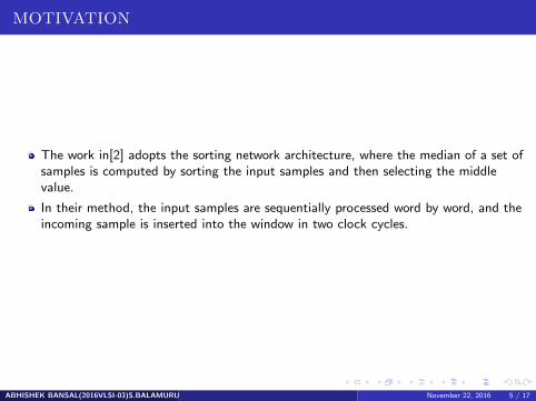
MOTIVATION
The work in[2] adopts the sorting network architecture, where the median of a set ofsamples is computed by sorting the input samples and then selecting the middlevalue.
In their method, the input samples are sequentially processed word by word, and theincoming sample is inserted into the window in two clock cycles.
ABHISHEK BANSAL(2016VLSI-03)S.BALAMURUGAN (2016VLSI-08)PRASHANT GAJBHIYE(2016VLSI-12)SHRADHESHWAR VERMA (2016VLSI-26) (emailID.com)November 22, 2016 5 / 17

MOTIVATION
In the first cycle, the oldest sample is removed from the window by moving some ofthe stored samples to the left.
In the second cycle, the incoming sample is compared with all the samples in thewindow and then inserted in the right place by moving some of them to the right.
This architecture has a latency of two clock cycles, and it generates only one medianoutput for every two cycles.
ABHISHEK BANSAL(2016VLSI-03)S.BALAMURUGAN (2016VLSI-08)PRASHANT GAJBHIYE(2016VLSI-12)SHRADHESHWAR VERMA (2016VLSI-26) (emailID.com)November 22, 2016 6 / 17

HOW TO ACHIEVE?
The improvement is achieved by performing the deletion and insertion of samples inone clock cycle, and a new control circuit is proposed to govern these two operations.
The hardware complexity is still proportional to the number of samples in the window
ABHISHEK BANSAL(2016VLSI-03)S.BALAMURUGAN (2016VLSI-08)PRASHANT GAJBHIYE(2016VLSI-12)SHRADHESHWAR VERMA (2016VLSI-26) (emailID.com)November 22, 2016 7 / 17
Architecture
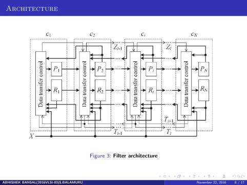
Figure 3: Filter architecture
ABHISHEK BANSAL(2016VLSI-03)S.BALAMURUGAN (2016VLSI-08)PRASHANT GAJBHIYE(2016VLSI-12)SHRADHESHWAR VERMA (2016VLSI-26) (emailID.com)November 22, 2016 8 / 17
Architecture
It consists of N cascaded blocks, one for each window rank.
Each cell block ci is composed of a data register (Ri ), an m-bit age register(Pi ), anda control unit for data transfer Register Ri stores the value of the sample in cellci .Register Pi keeps the age of this sample, i.e., the number of clock cycles thesample has experienced in the window.All cells are connected to a global input X,through which they receive the new input sample.
ABHISHEK BANSAL(2016VLSI-03)S.BALAMURUGAN (2016VLSI-08)PRASHANT GAJBHIYE(2016VLSI-12)SHRADHESHWAR VERMA (2016VLSI-26) (emailID.com)November 22, 2016 9 / 17
Architecture
At each machine cycle, depending on the value of the input sample, the datatransfer control unit determines if each cell will keep its original sample, receive theinput sample from the outside, or receive the sample from its adjoining cell on theleft or right.
The window samples are stored in descending order from left to right, so that at anytime, the maximum sample is at the leftmost register (R1)
The minimum sample is at the rightmost register (RN). The median value of thewindow will be at the center cell (RN+1/2), assuming N is an odd number.
ABHISHEK BANSAL(2016VLSI-03)S.BALAMURUGAN (2016VLSI-08)PRASHANT GAJBHIYE(2016VLSI-12)SHRADHESHWAR VERMA (2016VLSI-26) (emailID.com)November 22, 2016 10 / 17

Circuit Behaviour
At each machine cycle, the architecture performs the following operations: find thecell with the oldest sample (called the oldest cell), find the cell for the input sampleto insert into the window (called the insertion cell), and update the sample in eachcell.
When the input sample is inserted in the insertion cell cj , the original cj and those inthe cells between cj and the oldest cell ck will all be shifted toward ck for one cell.
If the oldest cell ck is on the left (right) of the LI (RI) cell cj , the input sample isinserted in cj , and the original sample in cj and those in the cells between cj and ckwill all be shifted one cell-space left (right).
ABHISHEK BANSAL(2016VLSI-03)S.BALAMURUGAN (2016VLSI-08)PRASHANT GAJBHIYE(2016VLSI-12)SHRADHESHWAR VERMA (2016VLSI-26) (emailID.com)November 22, 2016 11 / 17

Circuit Behaviour
Figure 4: Work table
ABHISHEK BANSAL(2016VLSI-03)S.BALAMURUGAN (2016VLSI-08)PRASHANT GAJBHIYE(2016VLSI-12)SHRADHESHWAR VERMA (2016VLSI-26) (emailID.com)November 22, 2016 12 / 17
Circuit implementation
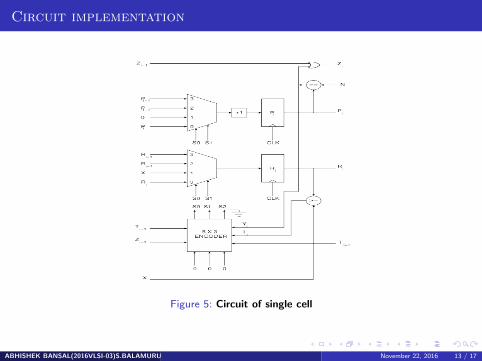
Figure 5: Circuit of single cell
ABHISHEK BANSAL(2016VLSI-03)S.BALAMURUGAN (2016VLSI-08)PRASHANT GAJBHIYE(2016VLSI-12)SHRADHESHWAR VERMA (2016VLSI-26) (emailID.com)November 22, 2016 13 / 17
Circuit implementation
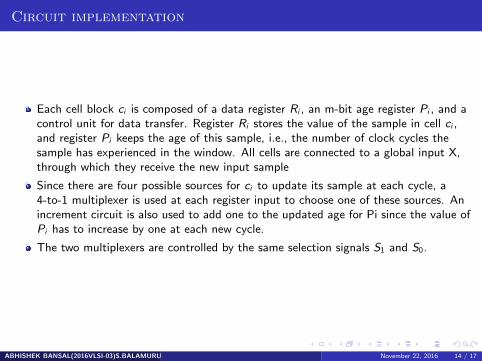
Each cell block ci is composed of a data register Ri , an m-bit age register Pi , and acontrol unit for data transfer. Register Ri stores the value of the sample in cell ci ,and register Pi keeps the age of this sample, i.e., the number of clock cycles thesample has experienced in the window. All cells are connected to a global input X,through which they receive the new input sample
Since there are four possible sources for ci to update its sample at each cycle, a4-to-1 multiplexer is used at each register input to choose one of these sources. Anincrement circuit is also used to add one to the updated age for Pi since the value ofPi has to increase by one at each new cycle.
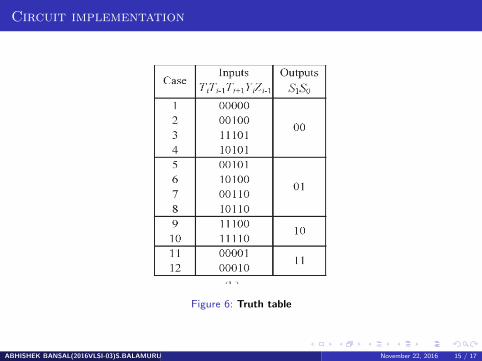
The two multiplexers are controlled by the same selection signals S1 and S0.
ABHISHEK BANSAL(2016VLSI-03)S.BALAMURUGAN (2016VLSI-08)PRASHANT GAJBHIYE(2016VLSI-12)SHRADHESHWAR VERMA (2016VLSI-26) (emailID.com)November 22, 2016 14 / 17
Circuit implementation
Figure 6: Truth table
ABHISHEK BANSAL(2016VLSI-03)S.BALAMURUGAN (2016VLSI-08)PRASHANT GAJBHIYE(2016VLSI-12)SHRADHESHWAR VERMA (2016VLSI-26) (emailID.com)November 22, 2016 15 / 17
Conclusion
The architecture of our 1-D median filter was implemented by the Verilog HDL
It is a word-level filter, receiving an input sample at each clock cycle and generatinga median output at the same cycle.
When an input sample enters the window, the sorting of existing samples is reusedin generating the new median output.
ABHISHEK BANSAL(2016VLSI-03)S.BALAMURUGAN (2016VLSI-08)PRASHANT GAJBHIYE(2016VLSI-12)SHRADHESHWAR VERMA (2016VLSI-26) (emailID.com)November 22, 2016 16 / 17
References
[1] Design of an Area-Efficient One-Dimensional Median Filter Ren-Der Chen, Pei-YinChen, Member, IEEE, and Chun-Hsien Yeh
[2] . V. G. Moshnyaga and K. Hashimoto, An efficient implementation of 1-D medianfilter,
[3] C.-T. Chen, L.-G. Chen, and J.-H. Hsiao, VLSI implementation of a selective medianfilter, IEEE Trans. Consum. Electron., vol. 42, no. 1, pp. 3342, Feb. 1996
[4] V. V. R. Teja, K. C. Ray, I. Chakrabarti, and A. S. Dhar, High throughput VLSIarchitecture for one dimensional median filter, in Proc. ICSCN, 2008, pp. 339344
ABHISHEK BANSAL(2016VLSI-03)S.BALAMURUGAN (2016VLSI-08)PRASHANT GAJBHIYE(2016VLSI-12)SHRADHESHWAR VERMA (2016VLSI-26) (emailID.com)November 22, 2016 17 / 17
![Hierarchical Histogram-based Median Filter for GPUsuni-obuda.hu/journal/Szanto_Feher_81.pdf · The generalization of the median filter is the rank order filter [3], where the output](https://img.pdfslide.net/doc/110x75/5e4b6ea61618287113519871/hierarchical-histogram-based-median-filter-for-gpusuni-obudahujournalszantofeher81pdf.jpg)


![TEAM2014-Template - Hrvatska znanstvena bibliografija Web view · 2015-10-26Standard median filter removes impulse noise and preserve image edges [2]. However, median filter has detail](https://img.pdfslide.net/doc/110x75/5aa901fa7f8b9a90188c436d/team2014-template-hrvatska-znanstvena-bibliografija-web-view2015-10-26standard.jpg)