Embed Size (px)
Citation preview
Chapter 2 Solutions
Page 1 of 19
Download Full Solutions manual for Design of Wood Structures-ASD/LRFD 6th Edition, at
http://testbankcollection.com/download/solutions-manual-for-design-of-wood-structures-
asdlrfd-6th-edition
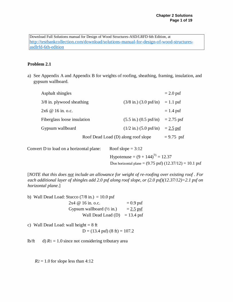
Problem 2.1
a) See Appendix A and Appendix B for weights of roofing, sheathing, framing, insulation, and
gypsum wallboard.
Asphalt shingles = 2.0 psf
3/8 in. plywood sheathing (3/8 in.) (3.0 psf/in) = 1.1 psf
2x6 @ 16 in. o.c. = 1.4 psf
Fiberglass loose insulation (5.5 in.) (0.5 psf/in) = 2.75 psf
Gypsum wallboard (1/2 in.) (5.0 psf/in) = 2.5 psf
Roof Dead Load (D) along roof slope = 9.75 psf
Convert D to load on a horizontal plane: Roof slope = 3:12
Hypotenuse = (9 + 144)½
= 12.37
Don horizontal plane = (9.75 psf) (12.37/12) = 10.1 psf
[NOTE that this does not include an allowance for weight of re-roofing over existing roof . For
each additional layer of shingles add 2.0 psf along roof slope, or (2.0 psf)(12.37/12)=2.1 psf on
horizontal plane.]
b) Wall Dead Load: Stucco (7/8 in.) = 10.0 psf
2x4 @ 16 in. o.c. = 0.9 psf
Gypsum wallboard (½ in.) = 2.5 psf
Wall Dead Load (D) = 13.4 psf
c) Wall Dead Load: wall height = 8 ft
D = (13.4 psf) (8 ft) = 107.2
lb/ft d) R1 = 1.0 since not considering tributary area
R2 = 1.0 for slope less than 4:12
Chapter 2 Solutions
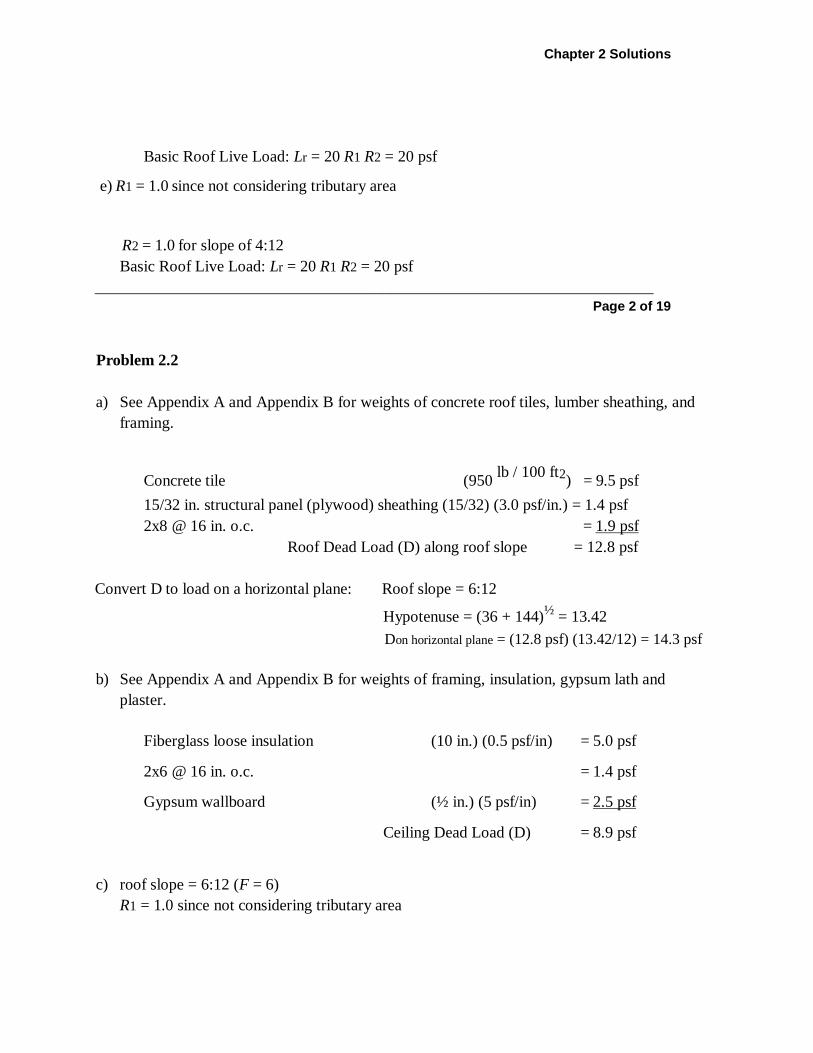
Basic Roof Live Load: Lr = 20 R1 R2 = 20 psf
e) R1 = 1.0 since not considering tributary area
R2 = 1.0 for slope of 4:12
Basic Roof Live Load: Lr = 20 R1 R2 = 20 psf
______________________________________________________________________
Page 2 of 19
Problem 2.2
a) See Appendix A and Appendix B for weights of concrete roof tiles, lumber sheathing, and
framing.
Concrete tile (950 lb / 100 ft2
) = 9.5 psf
15/32 in. structural panel (plywood) sheathing (15/32) (3.0 psf/in.) = 1.4 psf
2x8 @ 16 in. o.c. = 1.9 psf
Roof Dead Load (D) along roof slope = 12.8 psf
Convert D to load on a horizontal plane: Roof slope = 6:12
Hypotenuse = (36 + 144)½
= 13.42
Don horizontal plane = (12.8 psf) (13.42/12) = 14.3 psf
b) See Appendix A and Appendix B for weights of framing, insulation, gypsum lath and
plaster.
Fiberglass loose insulation (10 in.) (0.5 psf/in) = 5.0 psf
2x6 @ 16 in. o.c. = 1.4 psf
Gypsum wallboard (½ in.) (5 psf/in) = 2.5 psf
Ceiling Dead Load (D) = 8.9 psf
c) roof slope = 6:12 (F = 6)
R1 = 1.0 since not considering tributary area
Chapter 2 Solutions Page 3 of 19
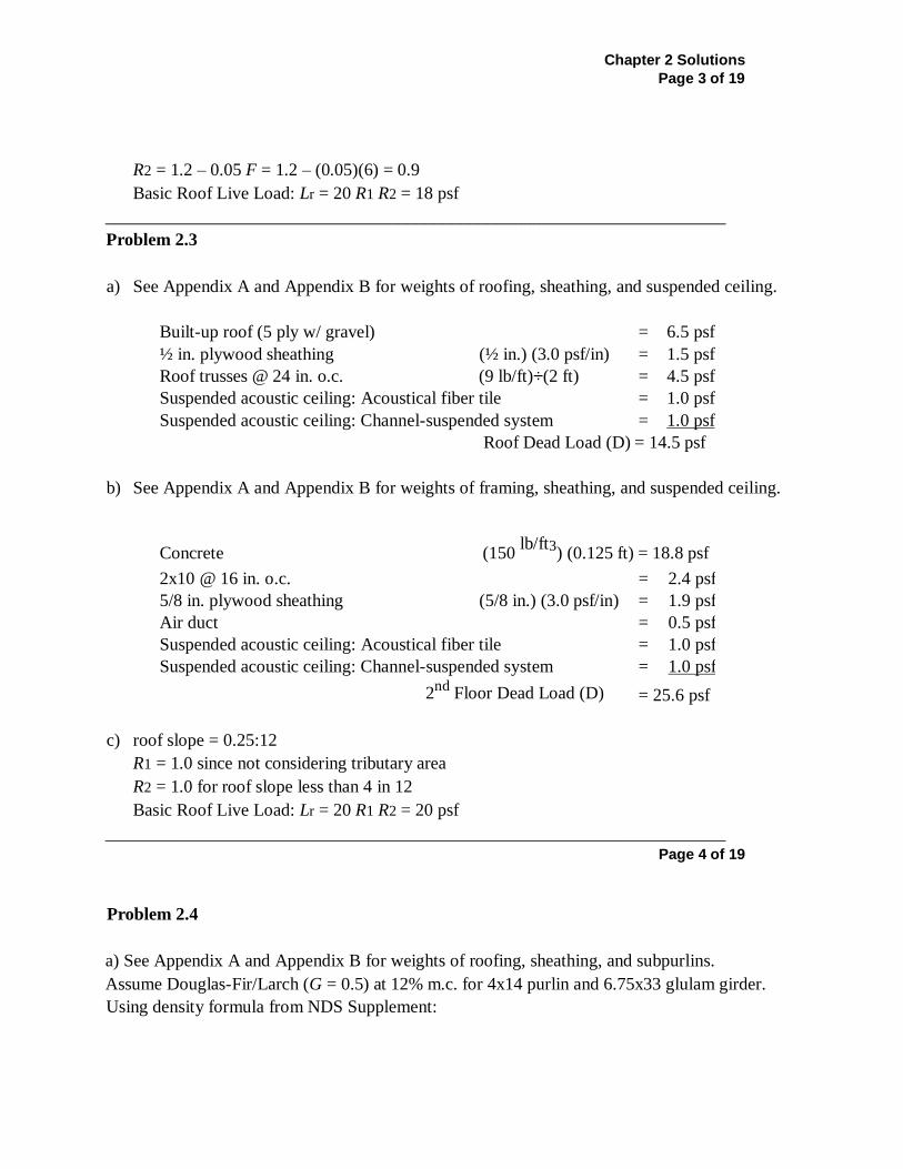
R2 = 1.2 – 0.05 F = 1.2 – (0.05)(6) = 0.9
Basic Roof Live Load: Lr = 20 R1 R2 = 18 psf
______________________________________________________________________
Problem 2.3
a) See Appendix A and Appendix B for weights of roofing, sheathing, and suspended ceiling.
Built-up roof (5 ply w/ gravel) = 6.5 psf
½ in. plywood sheathing (½ in.) (3.0 psf/in) = 1.5 psf
Roof trusses @ 24 in. o.c. (9 lb/ft)÷(2 ft) = 4.5 psf
Suspended acoustic ceiling: Acoustical fiber tile = 1.0 psf
Suspended acoustic ceiling: Channel-suspended system = 1.0 psf
Roof Dead Load (D) = 14.5 psf
b) See Appendix A and Appendix B for weights of framing, sheathing, and suspended ceiling.
Concrete (150 lb/ft3
) (0.125 ft) = 18.8 psf
2x10 @ 16 in. o.c. = 2.4 psf
5/8 in. plywood sheathing (5/8 in.) (3.0 psf/in) = 1.9 psf
Air duct = 0.5 psf
Suspended acoustic ceiling: Acoustical fiber tile = 1.0 psf
Suspended acoustic ceiling: Channel-suspended system = 1.0 psf
2nd
Floor Dead Load (D) = 25.6 psf
c) roof slope = 0.25:12
R1 = 1.0 since not considering tributary area
R2 = 1.0 for roof slope less than 4 in 12
Basic Roof Live Load: Lr = 20 R1 R2 = 20 psf
______________________________________________________________________
Page 4 of 19
Problem 2.4
a) See Appendix A and Appendix B for weights of roofing, sheathing, and subpurlins.
Assume Douglas-Fir/Larch (G = 0.5) at 12% m.c. for 4x14 purlin and 6.75x33 glulam girder.
Using density formula from NDS Supplement:
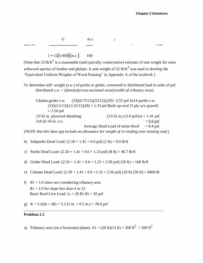
Chapter 2 Solutions
G m.c. 3
density = 62.4
1 + = 33 lb/ft
1 + G(0.009)(m.c.) 100
[Note that 33 lb/ft3 is a reasonable (and typically conservative) estimate of unit weight for most
softwood species of lumber and glulam. A unit weight of 33 lb/ft3 was used to develop the
“Equivalent Uniform Weights of Wood Framing” in Appendix A of the textbook.]
To determine self- weight (s.w.) of purlin or girder, converted to distributed load in units of psf:
distributed s.w. = (density)(cross-sectional area)/(width of tributary area)
Glulam girder s.w. (33)(6.75/12)(33/12)/(20)= 2.55 psf 4x14 purlin s.w.
(33)(3.5/12)(13.25/12)/(8) = 1.33 psf Built-up roof (5 ply w/o gravel)
= 2.50 psf
15/32 in. plywood sheathing (15/32 in.) (3.0 psf/in) = 1.41 psf
2x4 @ 24 in. o.c. = 0.6 psf
Average Dead Load of entire Roof = 8.4 psf
(NOTE that this does not include an allowance for weight of re-roofing over existing roof.)
b) Subpurlin Dead Load: (2.50 + 1.41 + 0.6 psf) (2 ft) = 9.0 lb/ft
c) Purlin Dead Load: (2.50 + 1.41 + 0.6 + 1.33 psf) (8 ft) = 46.7 lb/ft
d) Girder Dead Load: (2.50 + 1.41 + 0.6 + 1.33 + 2.56 psf) (20 ft) = 168 lb/ft
e) Column Dead Load: (2.50 + 1.41 + 0.6 +1.33 + 2.56 psf) (20 ft) (50 ft) = 8400 lb
f) R1 = 1.0 since not considering tributary area
R2 = 1.0 for slope less than 4 in 12
Basic Roof Live Load: Lr = 20 R1 R2 = 20 psf
g) R = 5.2(ds + dh) = 5.2 (5 in. + 0.5 in.) = 28.6 psf
______________________________________________________________________
Problem 2.5
a) Tributary area (on a horizontal plane): AT = (20 ft)(13 ft) = 260 ft2 > 200 ft
2
Chapter 2 Solutions Page 5 of 19
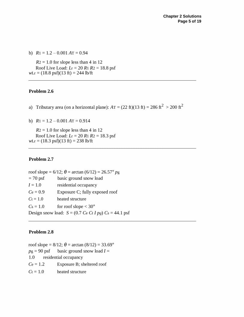
b) R1 = 1.2 – 0.001 AT = 0.94
R2 = 1.0 for slope less than 4 in 12
Roof Live Load: Lr = 20 R1 R2 = 18.8 psf wLr = (18.8 psf)(13 ft) = 244 lb/ft
______________________________________________________________________
Problem 2.6
a) Tributary area (on a horizontal plane): AT = (22 ft)(13 ft) = 286 ft2 > 200 ft
2
b) R1 = 1.2 – 0.001 AT = 0.914
R2 = 1.0 for slope less than 4 in 12
Roof Live Load: Lr = 20 R1 R2 = 18.3 psf wLr = (18.3 psf)(13 ft) = 238 lb/ft
______________________________________________________________________
Problem 2.7
roof slope = 6/12; θ = arctan (6/12) = 26.57° pg
= 70 psf basic ground snow load
I = 1.0 residential occupancy
Ce = 0.9 Exposure C; fully exposed roof
Ct = 1.0 heated structure
Cs = 1.0 for roof slope < 30°
Design snow load: S = (0.7 Ce Ct I pg) Cs = 44.1 psf
______________________________________________________________________
Problem 2.8
roof slope = 8/12; θ = arctan (8/12) = 33.69°
pg = 90 psf basic ground snow load I =
1.0 residential occupancy
Ce = 1.2 Exposure B; sheltered roof
Ct = 1.0 heated structure
Chapter 2 Solutions
Cs = 0.908 for roof slope of 33.69°
(linear interpolation between Cs = 1 for θ = 30° and Cs = 0 for θ =
70 °) Design snow load: S = (0.7 Ce Ct I pg) Cs = 68.6 psf
______________________________________________________________________
Chapter 2 Solutions Page 7 of 19
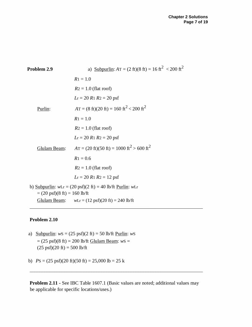
Problem 2.9 a) Subpurlin: AT = (2 ft)(8 ft) = 16 ft2 < 200 ft
2
R1 = 1.0
R2 = 1.0 (flat roof)
Lr = 20 R1 R2 = 20 psf
Purlin: AT = (8 ft)(20 ft) = 160 ft2 < 200 ft
2
R1 = 1.0
R2 = 1.0 (flat roof)
Lr = 20 R1 R2 = 20 psf
Glulam Beam: AT = (20 ft)(50 ft) = 1000 ft2
> 600 ft2
R1 = 0.6
R2 = 1.0 (flat roof)
Lr = 20 R1 R2 = 12 psf
b) Subpurlin: wLr = (20 psf)(2 ft) = 40 lb/ft Purlin: wLr
= (20 psf)(8 ft) = 160 lb/ft
Glulam Beam: wLr = (12 psf)(20 ft) = 240 lb/ft
______________________________________________________________________
Problem 2.10
a) Subpurlin: wS = (25 psf)(2 ft) = 50 lb/ft Purlin: wS
= (25 psf)(8 ft) = 200 lb/ft Glulam Beam: wS =
(25 psf)(20 ft) = 500 lb/ft
b) PS = (25 psf)(20 ft)(50 ft) = 25,000 lb = 25 k
______________________________________________________________________
Problem 2.11 - See IBC Table 1607.1 (Basic values are noted; additional values may
be applicable for specific locations/uses.)
Chapter 2 Solutions Page 8 of 19
nd
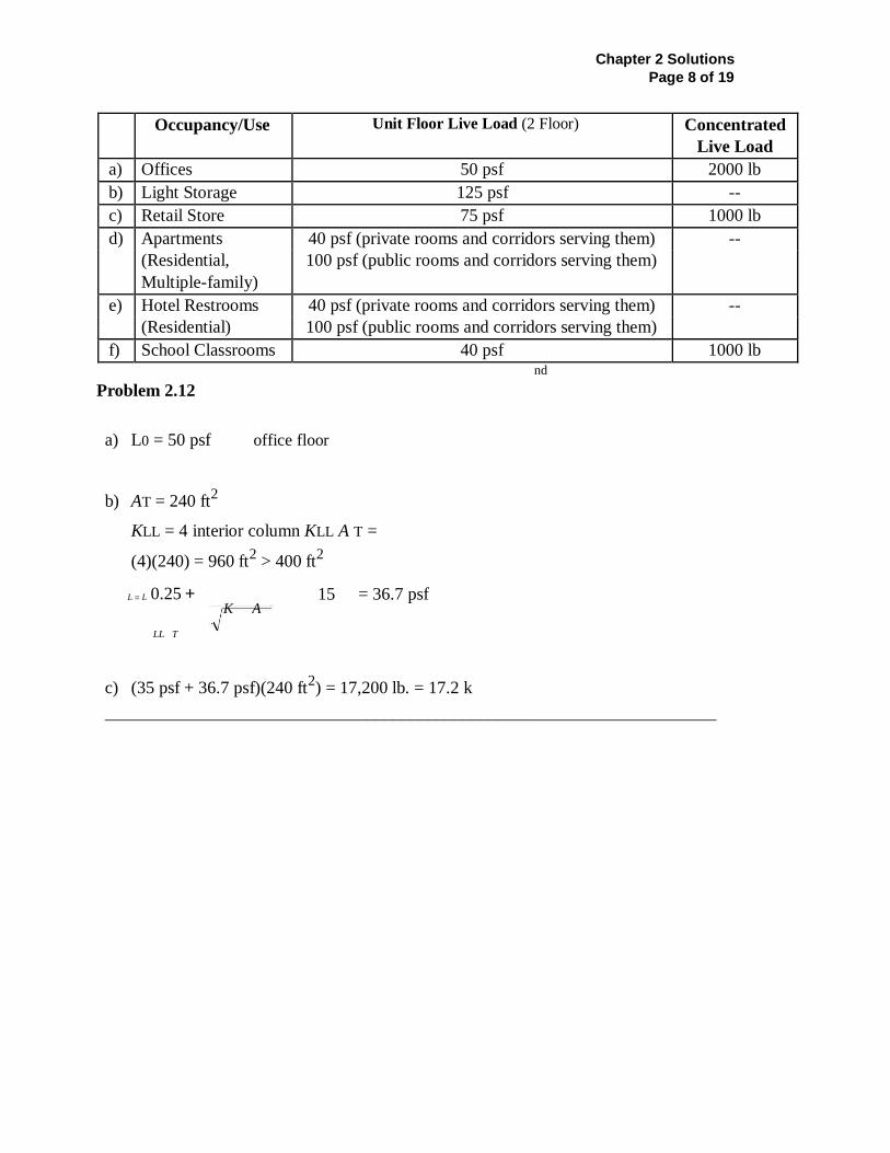
Problem 2.12
a) L0 = 50 psf office floor
b) AT = 240 ft2
KLL = 4 interior column KLL A T =
(4)(240) = 960 ft2 > 400 ft
2
L = L 0.25 + 15
= 36.7 psf
LL T
c) (35 psf + 36.7 psf)(240 ft2) = 17,200 lb. = 17.2 k
______________________________________________________________________
Occupancy/Use
Unit Floor Live Load (2 Floor) Concentrated
Live Load
a) Offices 50 psf 2000 lb
b) Light Storage 125 psf --
c) Retail Store 75 psf 1000 lb
d) Apartments 40 psf (private rooms and corridors serving them) --
(Residential,
Multiple-family)
100 psf (public rooms and corridors serving them)
e) Hotel Restrooms 40 psf (private rooms and corridors serving them) --
(Residential) 100 psf (public rooms and corridors serving them)
f) School Classrooms 40 psf 1000 lb
K A
Chapter 2 Solutions Page 9 of 19
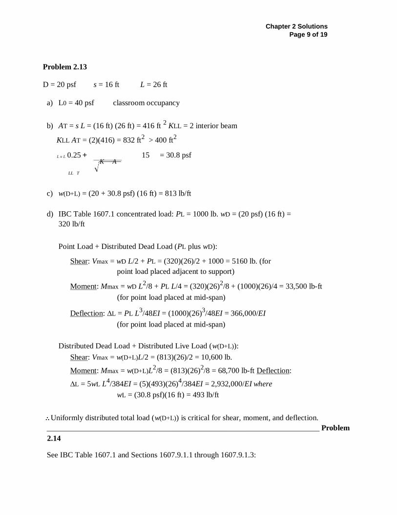
Problem 2.13
D = 20 psf s = 16 ft L = 26 ft
a) L0 = 40 psf classroom occupancy
b) AT = s L = (16 ft) (26 ft) = 416 ft 2 KLL = 2 interior beam
KLL AT = (2)(416) = 832 ft2 > 400 ft
2
L = L 0.25 + 15
= 30.8 psf
LL T
c) w(D+L) = (20 + 30.8 psf) (16 ft) = 813 lb/ft
d) IBC Table 1607.1 concentrated load: PL = 1000 lb. wD = (20 psf) (16 ft) =
320 lb/ft
Point Load + Distributed Dead Load (PL plus wD):
Shear: Vmax = wD L/2 + PL = (320)(26)/2 + 1000 = 5160 lb. (for
point load placed adjacent to support)
Moment: Mmax = wD L2/8 + PL L/4 = (320)(26)
2/8 + (1000)(26)/4 = 33,500 lb-ft
(for point load placed at mid-span)
Deflection: ∆L = PL L3/48EI = (1000)(26)
3/48EI = 366,000/EI
(for point load placed at mid-span)
Distributed Dead Load + Distributed Live Load (w(D+L)):
Shear: Vmax = w(D+L)L/2 = (813)(26)/2 = 10,600 lb.
Moment: Mmax = w(D+L)L2/8 = (813)(26)
2/8 = 68,700 lb-ft Deflection:
∆L = 5wL L4/384EI = (5)(493)(26)
4/384EI = 2,932,000/EI where
wL = (30.8 psf)(16 ft) = 493 lb/ft
Uniformly distributed total load (w(D+L)) is critical for shear, moment, and deflection.
______________________________________________________________________ Problem
2.14
See IBC Table 1607.1 and Sections 1607.9.1.1 through 1607.9.1.3:
K A
Chapter 2 Solutions Page 10 of 19
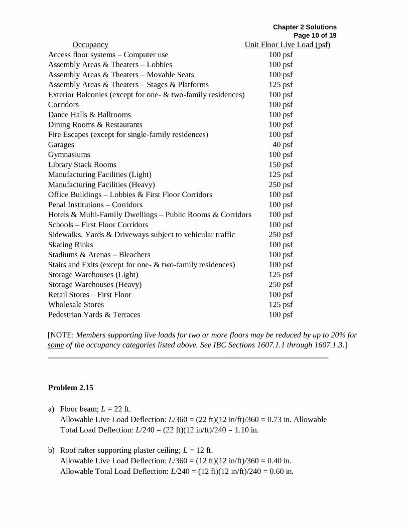
Occupancy Unit Floor Live Load (psf)
Access floor systems – Computer use 100 psf
Assembly Areas & Theaters – Lobbies 100 psf
Assembly Areas & Theaters – Movable Seats 100 psf
Assembly Areas & Theaters – Stages & Platforms 125 psf
Exterior Balconies (except for one- & two-family residences) 100 psf
Corridors 100 psf
Dance Halls & Ballrooms 100 psf
Dining Rooms & Restaurants 100 psf
Fire Escapes (except for single-family residences) 100 psf
Garages 40 psf
Gymnasiums 100 psf
Library Stack Rooms 150 psf
Manufacturing Facilities (Light) 125 psf
Manufacturing Facilities (Heavy) 250 psf
Office Buildings – Lobbies & First Floor Corridors 100 psf
Penal Institutions – Corridors 100 psf
Hotels & Multi-Family Dwellings – Public Rooms & Corridors 100 psf
Schools – First Floor Corridors 100 psf
Sidewalks, Yards & Driveways subject to vehicular traffic 250 psf
Skating Rinks 100 psf
Stadiums & Arenas – Bleachers 100 psf
Stairs and Exits (except for one- & two-family residences) 100 psf
Storage Warehouses (Light) 125 psf
Storage Warehouses (Heavy) 250 psf
Retail Stores – First Floor 100 psf
Wholesale Stores 125 psf
Pedestrian Yards & Terraces 100 psf
[NOTE: Members supporting live loads for two or more floors may be reduced by up to 20% for
some of the occupancy categories listed above. See IBC Sections 1607.1.1 through 1607.1.3.]
______________________________________________________________________
Problem 2.15
a) Floor beam; L = 22 ft.
Allowable Live Load Deflection: L/360 = (22 ft)(12 in/ft)/360 = 0.73 in. Allowable
Total Load Deflection: L/240 = (22 ft)(12 in/ft)/240 = 1.10 in.
b) Roof rafter supporting plaster ceiling; L = 12 ft.
Allowable Live Load Deflection: L/360 = (12 ft)(12 in/ft)/360 = 0.40 in.
Allowable Total Load Deflection: L/240 = (12 ft)(12 in/ft)/240 = 0.60 in.

Chapter 2 Solutions Page 11 of 19
______________________________________________________________________
Chapter 2 Solutions Page 12 of 19
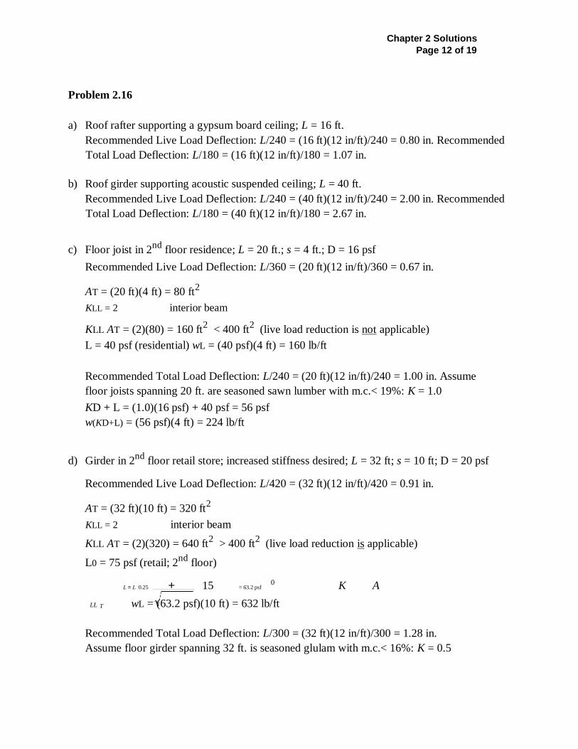
Problem 2.16
a) Roof rafter supporting a gypsum board ceiling; L = 16 ft.
Recommended Live Load Deflection: L/240 = (16 ft)(12 in/ft)/240 = 0.80 in. Recommended
Total Load Deflection: L/180 = (16 ft)(12 in/ft)/180 = 1.07 in.
b) Roof girder supporting acoustic suspended ceiling; L = 40 ft.
Recommended Live Load Deflection: L/240 = (40 ft)(12 in/ft)/240 = 2.00 in. Recommended
Total Load Deflection: L/180 = (40 ft)(12 in/ft)/180 = 2.67 in.
c) Floor joist in 2nd
floor residence; L = 20 ft.; s = 4 ft.; D = 16 psf
Recommended Live Load Deflection: L/360 = (20 ft)(12 in/ft)/360 = 0.67 in.
AT = (20 ft)(4 ft) = 80 ft2
KLL = 2 interior beam
KLL AT = (2)(80) = 160 ft2 < 400 ft
2 (live load reduction is not applicable)
L = 40 psf (residential) wL = (40 psf)(4 ft) = 160 lb/ft
Recommended Total Load Deflection: L/240 = (20 ft)(12 in/ft)/240 = 1.00 in. Assume
floor joists spanning 20 ft. are seasoned sawn lumber with m.c.< 19%: K = 1.0
KD + L = (1.0)(16 psf) + 40 psf = 56 psf
w(KD+L) = (56 psf)(4 ft) = 224 lb/ft
d) Girder in 2nd
floor retail store; increased stiffness desired; L = 32 ft; s = 10 ft; D = 20 psf
Recommended Live Load Deflection: L/420 = (32 ft)(12 in/ft)/420 = 0.91 in.
AT = (32 ft)(10 ft) = 320 ft2
KLL = 2 interior beam
KLL AT = (2)(320) = 640 ft2 > 400 ft
2 (live load reduction is applicable)
L0 = 75 psf (retail; 2nd
floor)
L = L 0.25 + 15 = 63.2 psf
0 K A
LL T wL = (63.2 psf)(10 ft) = 632 lb/ft
Recommended Total Load Deflection: L/300 = (32 ft)(12 in/ft)/300 = 1.28 in.
Assume floor girder spanning 32 ft. is seasoned glulam with m.c.< 16%: K = 0.5
Chapter 2 Solutions Page 13 of 19
KD + L = (0.5)(20 psf) + 63.2 psf = 73.2 psf w(KD+L) = (73.2 psf)(10 ft) = 732 lb/ft
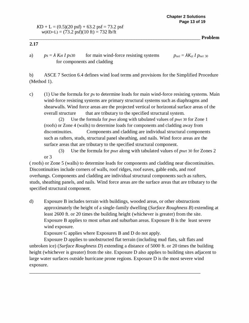
______________________________________________________________________ Problem
2.17
a) ps = λ Kzt I ps30 for main wind-force resisting systems pnet = λKzt I pnet 30
for components and cladding
b) ASCE 7 Section 6.4 defines wind load terms and provisions for the Simplified Procedure
(Method 1).
c) (1) Use the formula for ps to determine loads for main wind-force resisting systems. Main
wind-force resisting systems are primary structural systems such as diaphragms and
shearwalls. Wind force areas are the projected vertical or horizontal surface areas of the
overall structure that are tributary to the specified structural system.
(2) Use the formula for pnet along with tabulated values of pnet 30 for Zone 1
(roofs) or Zone 4 (walls) to determine loads for components and cladding away from
discontinuities. Components and cladding are individual structural components
such as rafters, studs, structural panel sheathing, and nails. Wind force areas are the
surface areas that are tributary to the specified structural component.
(3) Use the formula for pnet along with tabulated values of pnet 30 for Zones 2
or 3
( roofs) or Zone 5 (walls) to determine loads for components and cladding near discontinuities.
Discontinuities include corners of walls, roof ridges, roof eaves, gable ends, and roof
overhangs. Components and cladding are individual structural components such as rafters,
studs, sheathing panels, and nails. Wind force areas are the surface areas that are tributary to the
specified structural component.
d) Exposure B includes terrain with buildings, wooded areas, or other obstructions
approximately the height of a single-family dwelling (Surface Roughness B) extending at
least 2600 ft. or 20 times the building height (whichever is greater) from the site.
Exposure B applies to most urban and suburban areas. Exposure B is the least severe
wind exposure.
Exposure C applies where Exposures B and D do not apply.
Exposure D applies to unobstructed flat terrain (including mud flats, salt flats and
unbroken ice) (Surface Roughness D) extending a distance of 5000 ft. or 20 times the building
height (whichever is greater) from the site. Exposure D also applies to building sites adjacent to
large water surfaces outside hurricane prone regions. Exposure D is the most severe wind
exposure.
______________________________________________________________________
Chapter 2 Solutions Page 14 of 19
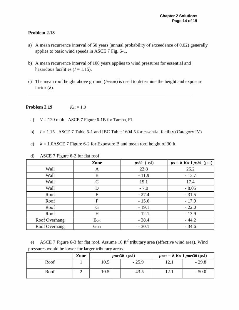
Problem 2.18
a) A mean recurrence interval of 50 years (annual probability of exceedence of 0.02) generally
applies to basic wind speeds in ASCE 7 Fig. 6-1.
b) A mean recurrence interval of 100 years applies to wind pressures for essential and
hazardous facilities (I = 1.15).
c) The mean roof height above ground (hmean) is used to determine the height and exposure
factor (λ).
______________________________________________________________________
Problem 2.19 Kzt = 1.0
a) V = 120 mph ASCE 7 Figure 6-1B for Tampa, FL
b) I = 1.15 ASCE 7 Table 6-1 and IBC Table 1604.5 for essential facility (Category IV)
c) λ = 1.0ASCE 7 Figure 6-2 for Exposure B and mean roof height of 30 ft.
d) ASCE 7 Figure 6-2 for flat roof
Zone ps30 (psf) ps = λ Kzt I ps30 (psf)
Wall A 22.8 26.2
Wall B - 11.9 - 13.7
Wall C 15.1 17.4
Wall D - 7.0 - 8.05
Roof E - 27.4 - 31.5
Roof F - 15.6 - 17.9
Roof G - 19.1 - 22.0
Roof H - 12.1 - 13.9
Roof Overhang EOH - 38.4 - 44.2
Roof Overhang GOH - 30.1 - 34.6
e) ASCE 7 Figure 6-3 for flat roof. Assume 10 ft2 tributary area (effective wind area). Wind
pressures would be lower for larger tributary areas.
Zone pnet30 (psf) pnet = λ Kzt I pnet30 (psf)
Roof 1 10.5 - 25.9 12.1 - 29.8
Roof 2 10.5 - 43.5 12.1 - 50.0
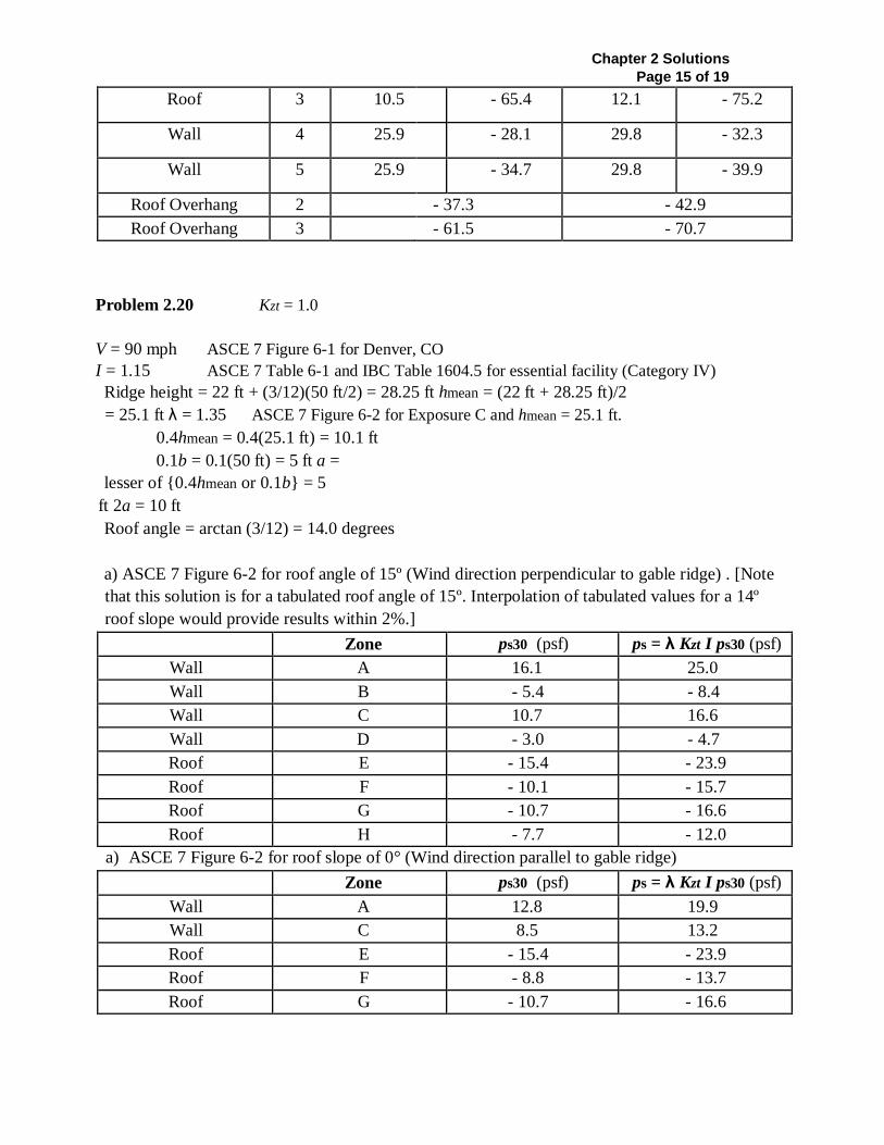
Chapter 2 Solutions Page 15 of 19
Roof 3 10.5 - 65.4 12.1 - 75.2
Wall 4 25.9 - 28.1 29.8 - 32.3
Wall 5 25.9 - 34.7 29.8 - 39.9
Roof Overhang 2 - 37.3 - 42.9
Roof Overhang 3 - 61.5 - 70.7
Problem 2.20 Kzt = 1.0
V = 90 mph ASCE 7 Figure 6-1 for Denver, CO
I = 1.15 ASCE 7 Table 6-1 and IBC Table 1604.5 for essential facility (Category IV)
Ridge height = 22 ft + (3/12)(50 ft/2) = 28.25 ft hmean = (22 ft + 28.25 ft)/2
= 25.1 ft λ = 1.35 ASCE 7 Figure 6-2 for Exposure C and hmean = 25.1 ft.
0.4hmean = 0.4(25.1 ft) = 10.1 ft
0.1b = 0.1(50 ft) = 5 ft a =
lesser of {0.4hmean or 0.1b} = 5
ft 2a = 10 ft
Roof angle = arctan (3/12) = 14.0 degrees
a) ASCE 7 Figure 6-2 for roof angle of 15º (Wind direction perpendicular to gable ridge) . [Note
that this solution is for a tabulated roof angle of 15º. Interpolation of tabulated values for a 14º
roof slope would provide results within 2%.]
Zone ps30 (psf) ps = λ Kzt I ps30 (psf)
Wall A 16.1 25.0
Wall B - 5.4 - 8.4
Wall C 10.7 16.6
Wall D - 3.0 - 4.7
Roof E - 15.4 - 23.9
Roof F - 10.1 - 15.7
Roof G - 10.7 - 16.6
Roof H - 7.7 - 12.0
a) ASCE 7 Figure 6-2 for roof slope of 0° (Wind direction parallel to gable ridge)
Zone ps30 (psf) ps = λ Kzt I ps30 (psf)
Wall A 12.8 19.9
Wall C 8.5 13.2
Roof E - 15.4 - 23.9
Roof F - 8.8 - 13.7
Roof G - 10.7 - 16.6
Chapter 2 Solutions Page 16 of 19
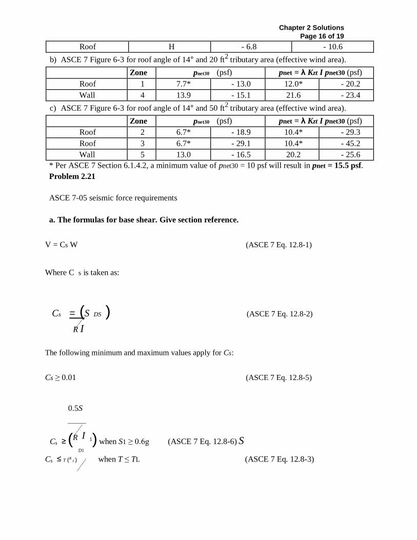
Roof H - 6.8 - 10.6
b) ASCE 7 Figure 6-3 for roof angle of 14° and 20 ft2 tributary area (effective wind area).
Zone pnet30 (psf) pnet = λ Kzt I pnet30 (psf)
Roof 1 7.7* - 13.0 12.0* - 20.2
Wall 4 13.9 - 15.1 21.6 - 23.4
c) ASCE 7 Figure 6-3 for roof angle of 14° and 50 ft2 tributary area (effective wind area).
Zone pnet30 (psf) pnet = λ Kzt I pnet30 (psf)
Roof 2 6.7* - 18.9 10.4* - 29.3
Roof 3 6.7* - 29.1 10.4* - 45.2
Wall 5 13.0 - 16.5 20.2 - 25.6
* Per ASCE 7 Section 6.1.4.2, a minimum value of pnet30 = 10 psf will result in pnet = 15.5 psf.
Problem 2.21
ASCE 7-05 seismic force requirements
a. The formulas for base shear. Give section reference.
V = Cs W (ASCE 7 Eq. 12.8-1)
Where C s is taken as:
Cs = (S DS ) (ASCE 7 Eq. 12.8-2)
R I
The following minimum and maximum values apply for Cs:
Cs ≥ 0.01 (ASCE 7 Eq. 12.8-5)
0.5S
Cs ≥ (R I 1) when S1 ≥ 0.6g (ASCE 7 Eq. 12.8-6) S D1
Cs ≤ T (R I ) when T ≤ TL (ASCE 7 Eq. 12.8-3)
Chapter 2 Solutions Page 17 of 19
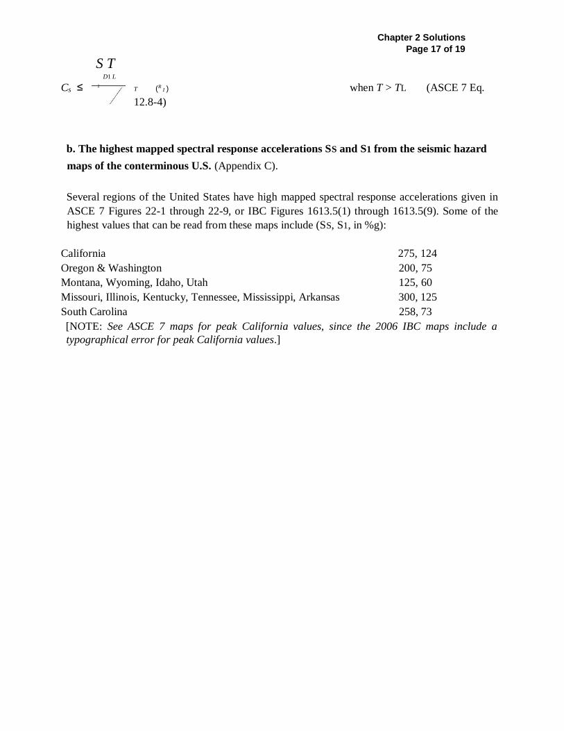
S T D1 L
Cs ≤ T (R I ) when T > TL (ASCE 7 Eq.
12.8-4)
b. The highest mapped spectral response accelerations SS and S1 from the seismic hazard
maps of the conterminous U.S. (Appendix C).
Several regions of the United States have high mapped spectral response accelerations given in
ASCE 7 Figures 22-1 through 22-9, or IBC Figures 1613.5(1) through 1613.5(9). Some of the
highest values that can be read from these maps include (SS, S1, in %g):
California 275, 124
Oregon & Washington 200, 75
Montana, Wyoming, Idaho, Utah 125, 60
Missouri, Illinois, Kentucky, Tennessee, Mississippi, Arkansas 300, 125
South Carolina 258, 73
[NOTE: See ASCE 7 maps for peak California values, since the 2006 IBC maps include a
typographical error for peak California values.]
2

The significance of SS and S1 is that they describe the anticipated seismic ground shaking hazard
that can be expected, based on available ground motion data, for structures with short and long
Chapter 2 Solutions Page 16 of 19
periods (0.2 and 1.0 seconds), respectively, based on Site Class B. These parameters serve as the
basis for the design response spectrum, from which seismic design forces are determined.
c. The maximum tabulated Site Coefficients Fa and Fv.
From ASCE 7 Table 11.4-1, the maximum value of Fa is 2.5 for Site Class E and SS ≤ 0.25.
From ASCE 7 Table 11.4-2, the maximum value of Fv is 3.5, for Site Class E and S1 ≤ 0.1.
The site coefficients modify the mapped spectral response accelerations for the soil profile at a
particular building location.
d. The maximum values of SMS, SM1, SDS and SD1 based on previous values.
Using the maximum mapped value of SS=300% or 3.0g, and multiplying by the highest Fa value
of 1.0 for SS>1.25g, the maximum value for SMS is 3.0g. Multiplying by 2/3, SDS is 2.0g.
The other possible combinations of SS and Fa from ASCE 7 Table 11.4-1 can be quickly checked
and found to be smaller: 0.25g(2.5)=0.625g, 0.5g(1.7)=0.85g, 0.75g(1.2)=0.90g,
1.00g(0.9)=0.90g.
Using the maximum mapped value of S1=125% or 1.25g, and multiplying by the highest Fv
value of 2.4 for S1>0.5g, the maximum value for SM1 is 3.0g. Multiplying by 2/3. SD1 is 2.0g.
The other possible combinations of S1 and Fv from ASCE 7 Table 11.4-2 can be quickly checked and
found to be smaller: 0.1g(3.5)=0.35g, 0.2g(3.2)=0.64g, 0.3g(2.8)=0.84g, 0.4g(2.4)=0.99g.
Problem 2.22
e. Briefly discuss the purpose of the R-factor. What value of R is used for a building with
wood-frame bearing walls that are sheathed with wood structural panel sheathing?
The R- factor is used to reduce seismic forces from the design response spectrum to design level
forces. The reduction is based on expected over strength (both in the system and individual
elements) and the expectation that elements can perform beyond the elastic stress range.
A building with light -frame bearing walls and sheathed with wood structural panel sheathing is
assigned an R-factor of 6.5. The R-factors are given in ASCE 7 Table 12.2-1.
Chapter 2 Solutions Page 17 of 19
ASCE 7-05 seismic force requirements
a. The definition of period of vibration and the methods for estimating the fundamental
period.
The period of vibration is the length of time that it takes for a structure to complete one cycle of
free vibration, and is a characteristic of the structure mass and stiffness. While other methods
involving building modeling may be used, the primary method is an approximate formula:
Ta = Ct hnx (ASCE 7 Eq. 12.8-7)
b. How does the period of vibration affect seismic forces?
Based on structural dynamics principles, buildings with the same fundamental period and same
damping have essentially the same response to an earthquake ground motion record. In general,
the anticipated seismic forces decrease for longer period buildings. For design purposes, wood
buildings generally have periods too short to suggest any decrease in force.
c. Describe the effects of the interaction of the soil and structure on seismic forces.
Local soil conditions, and particularly soft soils can significantly amplify earthquake ground
motions.
d. What is damping and how does it affect seismic forces? Do the ASCE 7 criteria take
damping into account?
Damping is resistance to motion provided by the building materials through mechanisms such as
friction, metal yielding and wood crushing. A low level of damping is assumed in the ASCE 7
design response spectrum. Additional damping is also considered in determining R-factors.
Problem 2.24
Chapter 2 Solutions
Page 18 of 19
ASCE 7 seismic force requirements
a. Briefly describe the general distribution of seismic forces over the height of a multi-story
building.
For all seismic design categories, for buildings with periods of 0.5 seconds or less, the Fx story
forces to the vertical resisting elements (such as shearwalls) will have a roughly triangular force
distribution, as per ASCE 7 Equations 12.8-11 and 12.8-12, and Example 2.14 of this text.
Fpx forces are described in Item b, below.
b. Describe differences in vertical distribution for vertical element and diaphragm forces
between Seismic Design Categories B and D.
Fpx story forces for design of diaphragms exhibit a vertical distribution similar to the distribution
of Fx forces for design of shearwalls in all Seismic Design Categories. The formula for Fpx is found
in ASCE 7 Equation 12.10-1, and Example 2.14 of this text.
c. Describe forces for out-of-plane design of wall components. Cite ASCE 7 provisions.
The formula for out-of-plane design of structural walls is Fp = 0.4SDS I Wp (see ASCE 7 Sec.
12.11).
For non-structural wall components with discrete attachments to the structure, and for structural
parapets, the design formula comes from ASCE 7 Sec. 13.3 (Eqs. 13.3-1 through 13.3-3):
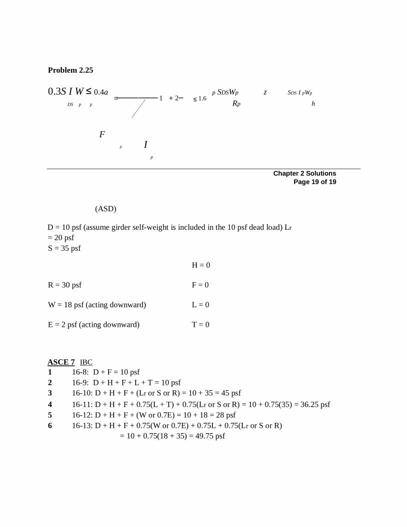
Problem 2.25
0.3S I W ≤ 0.4a p SDSWp z SDS I pWp
Rp h DS p p
F
p I
p
Chapter 2 Solutions
Page 19 of 19
(ASD)
D = 10 psf (assume girder self-weight is included in the 10 psf dead load) Lr
= 20 psf
S = 35 psf
H = 0
R = 30 psf F = 0
W = 18 psf (acting downward) L = 0
E = 2 psf (acting downward) T = 0
ASCE 7 IBC
1 16-8: D + F = 10 psf
2 16-9: D + H + F + L + T = 10 psf
3 16-10: D + H + F + (Lr or S or R) = 10 + 35 = 45 psf
4 16-11: D + H + F + 0.75(L + T) + 0.75(Lr or S or R) = 10 + 0.75(35) = 36.25 psf
5 16-12: D + H + F + (W or 0.7E) = 10 + 18 = 28 psf
6 16-13: D + H + F + 0.75(W or 0.7E) + 0.75L + 0.75(Lr or S or R)
= 10 + 0.75(18 + 35) = 49.75 psf
= 1 + 2
≤ 1.6
Problem 2.26
7 & 8 16-14 & 16-15: not applicable since W and E act in same direction as D
Maximum service load (for ASD) on the glulam girder is 49.75 psf based on ASCE 7 load combination 6 (IBC load combination 16 -13).
[Note that one of the other service load combinations may be critical for design, depending on
the applicable load duration factor, CD. See discussion of CD in Chapter 4 of the textbook.]
Problem 2.25 (LRFD)
Assume girder self-weight is included in the 10 psf dead load.
ASCE 7 IBC
1 16-1: 1.4(D + F) = 1.4(10) = 14 psf
2 16-2: 1.2(D + F + T) + 1.6(L + H) + 0.5(Lr or S or R) = 1.2(10) + 0.5(35) = 29.5 psf
3 16-3: 1.2D + 1.6(Lr or S or R) + (L or 0.8W) = 1.2(10) + 1.6(35) + 0.8(18) = 82.4 psf
4 16-4: 1.2D + 1.6W + L + 0.5(Lr or S or R) = 1.2(10) + 1.6(18) + 0.5(35) = 58.3 psf
5 16-5: 1.2D + E + L + 0.2S = 1.2(10) + 2 + 0.2(35) = 21 psf
6 & 7 16-6 & 16-7: not applicable since W and E act in same direction as D
Maximum factored load (for LRFD) on the glulam girder is 82.4 psf based on ASCE 7 load combination 3 (IBC load combination 16 -3).
[Note that one of the other factored load combinations may be critical for design, depending on
the applicable time effect factor, λ. See discussion of CD and λ in Chapter 4 of the textbook.]