Embed Size (px)
Citation preview
IOSR Journal of Mechanical and Civil Engineering (IOSR-JMCE)
e-ISSN: 2278-1684,p-ISSN: 2320-334X, Volume 8, Issue 5 (Sep. - Oct. 2013), PP 56-61 www.iosrjournals.org
www.iosrjournals.org 56 | Page
Experimental Test on Carbon Fiber/Epoxy and Glass Fiber
/Epoxy Pultruded Rods for Mechanical Properties
P. Krishna Vagdevi 1, B.Mahasenadhipathi Rao
2 & O.Vasudeva Reddy
3
1 (M.Tech (CAD/CAM) Student, Department of Mechanical engineering, Sreenidhi Institute of Science and
Technology, Hyderabad, (AP) India.) 2 (Supervisor, Assistant Professor, Department of Mechanical engineering, Sreenidhi Institute of Science and
Technology, Hyderabad, (AP) India )
3 (Managing Director, Advanced Millennium Materials, IDA, Cherlapally, phase-I, Hyderabad, (AP) India)
Abstract: In this work, composite rods of glass fiber/epoxy and carbon fiber/epoxy with 80% of fiber loading
and 20% of matrix are produced by using pultrusion technique. Pultrusion is a continuous process for
manufacture of composite materials with constant cross-section. Reinforced fibers are pulled through a resin,
possibly followed by a separate performing system, and into a heated die, where the resin
undergoes polymerization. Many resin types may be used in pultrusion
including polyester, polyurethane, vinylester and epoxy. These two types of rods are subjected to tensile test, chemical absorption and impact tests at various temperatures like room temperature and at below room
temperatures.
Keywords: composite rods, pultrusion, mechanical properties, chemical resistance
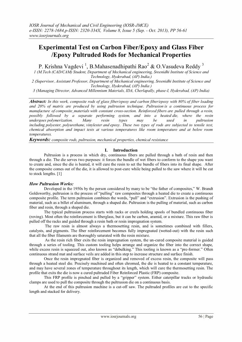
I. Introduction Pultrusion is a process in which dry, continuous fibers are pulled through a bath of resin and then
through a die. The die serves two purposes: it forces the bundle of wet fibers to conform to the shape you want to create and, since the die is heated, it will cure the resin to set the bundle of fibers into its final shape. After
the composite comes out of the die, it is allowed to post-cure while being pulled to the saw where it will be cut
to stock lengths. [1]
How Pultrusion Works: Developed in the 1950s by the person considered by many to be “the father of composites,” W. Brandt
Goldsworthy, pultrusion is the process of “pulling” raw composites through a heated die to create a continuous composite profile. The term pultrusion combines the words, “pull” and “extrusion”. Extrusion is the pushing of
material, such as a billet of aluminum, through a shaped die. Pultrusion is the pulling of material, such as carbon
fiber and resin, through a shaped die.
The typical pultrusion process starts with racks or creels holding spools of bundled continuous fiber
(roving). Most often the reinforcement is fiberglass, but it can be carbon, aramid, or a mixture. This raw fiber is
pulled off the racks and guided through a resin bath or resin impregnation system.
The raw resin is almost always a thermosetting resin, and is sometimes combined with fillers,
catalysts, and pigments. The fiber reinforcement becomes fully impregnated (wetted-out) with the resin such
that all the fiber filaments are thoroughly saturated with the resin mixture.
As the resin rich fiber exits the resin impregnation system, the un-cured composite material is guided
through a series of tooling. This custom tooling helps arrange and organize the fiber into the correct shape, while excess resin is squeezed out, also known as “debulking.” This tooling is known as a “pre-former.” Often
continuous strand mat and surface veils are added in this step to increase structure and surface finish.
Once the resin impregnated fiber is organized and removed of excess resin, the composite will pass
through a heated steel die. Precisely machined and often chromed, the die is heated to a constant temperature,
and may have several zones of temperature throughout its length, which will cure the thermosetting resin. The
profile that exits the die is now a cured pultruded Fiber Reinforced Plastic (FRP) composite.
This FRP profile is pinched and pulled by a “gripper” system. Either caterpillar tracks or hydraulic
clamps are used to pull the composite through the pultrusion die on a continuous basis.
At the end of this pultrusion machine is a cut-off saw. The pultruded profiles are cut to the specific
length and stacked for delivery.
Experimental Test On Carbon Fiber/Epoxy And Glass Fiber /Epoxy Pultruded Rods For Mechanical
www.iosrjournals.org 57 | Page
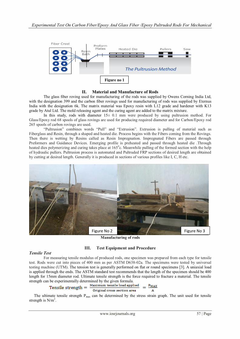
II. Material and Manufacture of Rods The glass fiber roving used for manufacturing of the rods was supplied by Owens Corning India Ltd,
with the designation 399 and the carbon fiber rovings used for manufacturing of rods was supplied by Eternus
India with the designation 6k. The matrix material was Epoxy resin with L12 grade and hardener with K13
grade by Atul Ltd. The mold releasing agent and the curing agent are added to the matrix mixture.
In this study, rods with diameter 15± 0.1 mm were produced by using pultrusion method. For
Glass/Epoxy rod 68 spools of glass rovings are used for producing required diameter and for Carbon/Epoxy rod
265 spools of carbon rovings are used.
“Pultrusion” combines words “Pull” and “Extrusion”. Extrusion is pulling of material such as Fiberglass and Resin, through a shaped and heated die. Process begins with the Fibers coming from the Rovings.
Then there is wetting by Resins called as Resin Impregnation. Impregnated Fibers are passed through
Preformers and Guidance Devices. Emerging profile is preheated and passed through heated die .Through
heated dies polymerizing and curing takes place at 1650c. Meanwhile pulling of the formed section with the help
of hydraulic pullers. Pultrusion process is automated and Pultruded FRP sections of desired length are obtained
by cutting at desired length. Generally it is produced in sections of various profiles like I, C, H etc.
Manufacturing of rods
III. Test Equipment and Procedure
Tensile Test For measuring tensile modulus of produced rods, one specimen was prepared from each type for tensile
test. Rods were cut into pieces of 400 mm as per ASTM D638-02a. The specimens were tested by universal
testing machine (UTM). The tension test is generally performed on flat or round specimens [3]. A uniaxial load
is applied through the ends. The ASTM standard test recommends that the length of the specimen should be 400
length for 15mm diameter rod. Ultimate tensile strength is the force required to fracture a material. The tensile
strength can be experimentally determined by the given formula.
The ultimate tensile strength Pmax can be determined by the stress strain graph. The unit used for tensile
strength is N/m2.
Figure no 1
Figure No 2 Figure No 3
Experimental Test On Carbon Fiber/Epoxy And Glass Fiber /Epoxy Pultruded Rods For Mechanical
www.iosrjournals.org 58 | Page
Chemical Resistance Testing ASTM D543 - 95, Standard Test Methods for Evaluating Resistance of Plastics to Chemical Reagents,
outlines test procedures for determining resistance of the rods to various chemical reagents by means of
reporting weight, dimensions, appearance, and strength properties, after a set duration period of immersion.
ASTM D543 does not specify the types or concentrations of reagents, duration of the test, or properties to be
reported. [5]
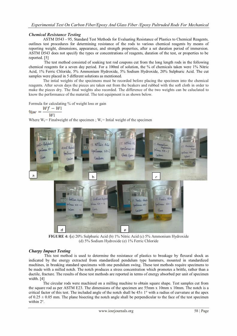
The test method consisted of soaking test rod coupons cut from the long length rods in the following
chemical reagents for a seven day period. For a 100ml of solution, the % of chemicals taken were 1% Nitric
Acid, 1% Ferric Chloride, 5% Ammonium Hydroxide, 5% Sodium Hydroxide, 20% Sulphuric Acid. The cut
samples were placed in 5 different solutions as mentioned.
The intial weights of the specimens must be recorded before placing the specimen into the chemical
reagents. After seven days the pieces are taken out from the beakers and rubbed with the soft cloth in order to make the pieces dry. The final weights also recorded. The difference of the two weights can be caluclated to
know the performance of the material. The test equipment is as shown below.
Formula for calculating % of weight loss or gain
Where Wf = Finalweight of the specimen ; Wi = Intial weight of the specimen
FIGURE 4: (a) 20% Sulphuric Acid (b) 1% Nitric Acid (c) 5% Ammonium Hydroxide
(d) 5% Sodium Hydroxide (e) 1% Ferric Chloride
Charpy Impact Testing This test method is used to determine the resistance of plastics to breakage by flexural shock as
indicated by the energy extracted from standardized pendulum type hammers, mounted in standardized
machines, in breaking standard specimens with one pendulum swing. These test methods require specimens to
be made with a milled notch. The notch produces a stress concentration which promotes a brittle, rather than a
ductile, fracture. The results of these test methods are reported in terms of energy absorbed per unit of specimen
width. [4]
The circular rods were machined on a milling machine to obtain square shape. Test samples cut from
the square rod as per ASTM E23. The dimensions of the specimen are 55mm x 10mm x 10mm. The notch is a
critical factor of this test. The included angle of the notch shall be 45± 1° with a radius of curvature at the apex
of 0.25 ± 0.05 mm. The plane bisecting the notch angle shall be perpendicular to the face of the test specimen
within 2°.
a b c
d e
Experimental Test On Carbon Fiber/Epoxy And Glass Fiber /Epoxy Pultruded Rods For Mechanical
www.iosrjournals.org 59 | Page
Charpy- V notch test is performed under room temperature and at three below temperatures like -150,-300,
and – 450. In order to achieve below room temperatures dry ice and acetone solvent were used.
IV. Results and Discussions
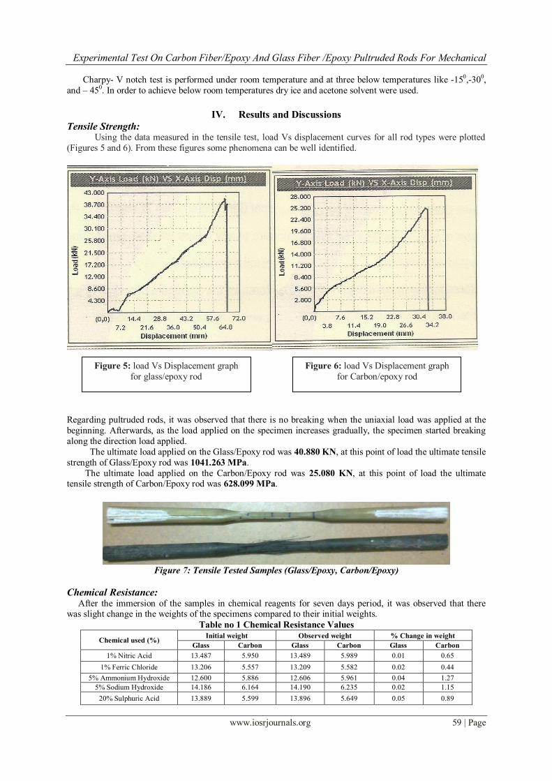
Tensile Strength: Using the data measured in the tensile test, load Vs displacement curves for all rod types were plotted
(Figures 5 and 6). From these figures some phenomena can be well identified.
Regarding pultruded rods, it was observed that there is no breaking when the uniaxial load was applied at the
beginning. Afterwards, as the load applied on the specimen increases gradually, the specimen started breaking
along the direction load applied.
The ultimate load applied on the Glass/Epoxy rod was 40.880 KN, at this point of load the ultimate tensile
strength of Glass/Epoxy rod was 1041.263 MPa.
The ultimate load applied on the Carbon/Epoxy rod was 25.080 KN, at this point of load the ultimate tensile strength of Carbon/Epoxy rod was 628.099 MPa.
Figure 7: Tensile Tested Samples (Glass/Epoxy, Carbon/Epoxy)
Chemical Resistance: After the immersion of the samples in chemical reagents for seven days period, it was observed that there was slight change in the weights of the specimens compared to their initial weights.
Table no 1 Chemical Resistance Values
Chemical used (%) Initial weight Observed weight % Change in weight
Glass Carbon Glass Carbon Glass Carbon
1% Nitric Acid 13.487 5.950 13.489 5.989 0.01 0.65
1% Ferric Chloride 13.206 5.557 13.209 5.582 0.02 0.44
5% Ammonium Hydroxide 12.600 5.886 12.606 5.961 0.04 1.27
5% Sodium Hydroxide 14.186 6.164 14.190 6.235 0.02 1.15
20% Sulphuric Acid 13.889 5.599 13.896 5.649 0.05 0.89
Figure 5: load Vs Displacement graph
for glass/epoxy rod
Figure 6: load Vs Displacement graph
for Carbon/epoxy rod
Experimental Test On Carbon Fiber/Epoxy And Glass Fiber /Epoxy Pultruded Rods For Mechanical
www.iosrjournals.org 60 | Page
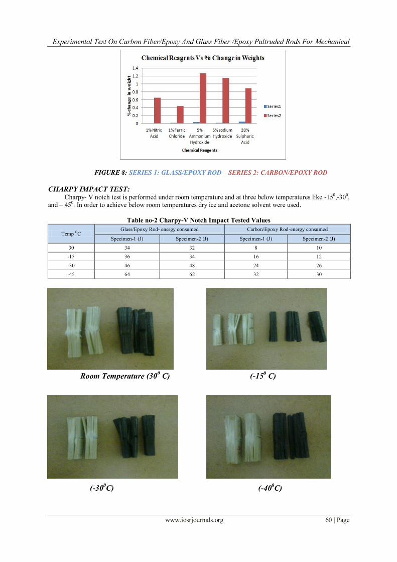
FIGURE 8: SERIES 1: GLASS/EPOXY ROD SERIES 2: CARBON/EPOXY ROD
CHARPY IMPACT TEST: Charpy- V notch test is performed under room temperature and at three below temperatures like -150,-300,
and – 450. In order to achieve below room temperatures dry ice and acetone solvent were used.
Table no-2 Charpy-V Notch Impact Tested Values
Temp OC
Glass/Epoxy Rod- energy consumed Carbon/Epoxy Rod-energy consumed
Specimen-1 (J) Specimen-2 (J) Specimen-1 (J) Specimen-2 (J)
30 34 32 8 10
-15 36 34 16 12
-30 46 48 24 26
-45 64 62 32 30
Room Temperature (300 C) (-15
0 C)
(-300C) (-40
0C)
Experimental Test On Carbon Fiber/Epoxy And Glass Fiber /Epoxy Pultruded Rods For Mechanical
www.iosrjournals.org 61 | Page
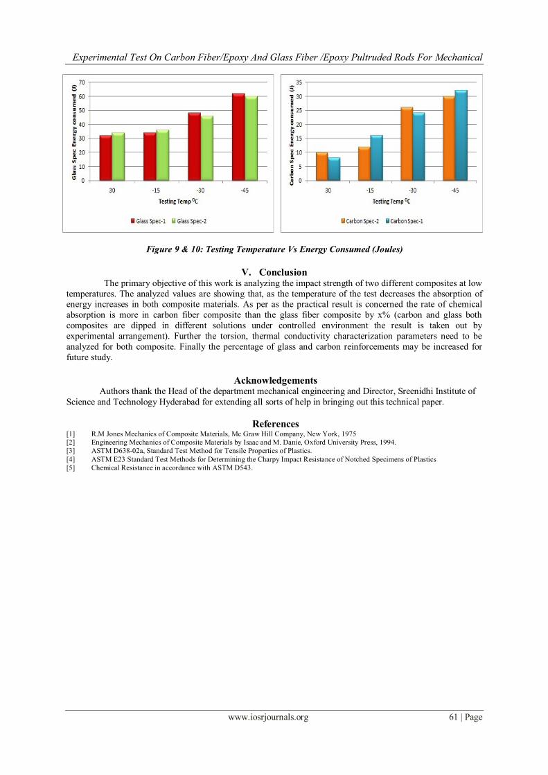
Figure 9 & 10: Testing Temperature Vs Energy Consumed (Joules)
V. Conclusion The primary objective of this work is analyzing the impact strength of two different composites at low
temperatures. The analyzed values are showing that, as the temperature of the test decreases the absorption of energy increases in both composite materials. As per as the practical result is concerned the rate of chemical
absorption is more in carbon fiber composite than the glass fiber composite by x% (carbon and glass both
composites are dipped in different solutions under controlled environment the result is taken out by
experimental arrangement). Further the torsion, thermal conductivity characterization parameters need to be
analyzed for both composite. Finally the percentage of glass and carbon reinforcements may be increased for
future study.
Acknowledgements Authors thank the Head of the department mechanical engineering and Director, Sreenidhi Institute of
Science and Technology Hyderabad for extending all sorts of help in bringing out this technical paper.
References [1] R.M Jones Mechanics of Composite Materials, Mc Graw Hill Company, New York, 1975
[2] Engineering Mechanics of Composite Materials by Isaac and M. Danie, Oxford University Press, 1994.
[3] ASTM D638-02a, Standard Test Method for Tensile Properties of Plastics.
[4] ASTM E23 Standard Test Methods for Determining the Charpy Impact Resistance of Notched Specimens of Plastics
[5] Chemical Resistance in accordance with ASTM D543.