Embed Size (px)
Citation preview
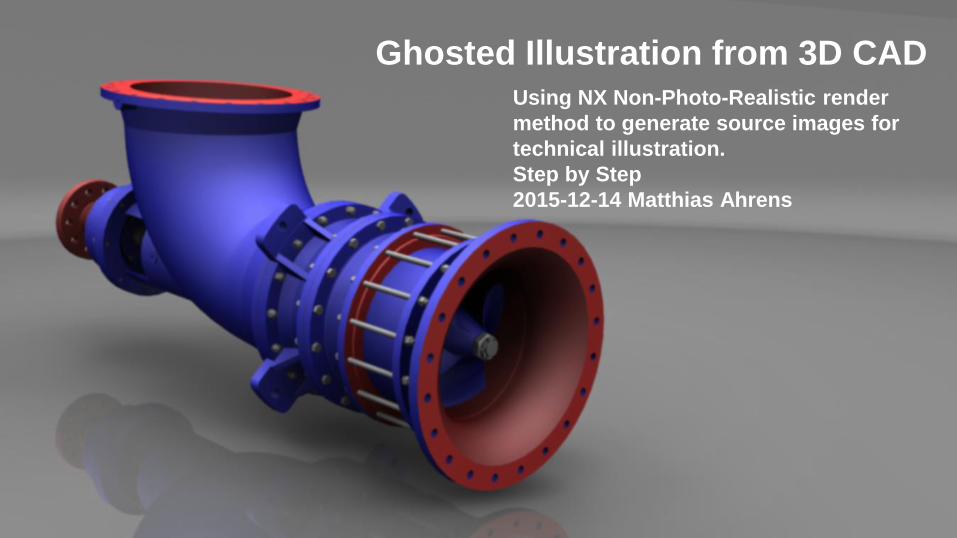
Using NX Non-Photo-Realistic render
method to generate source images for
technical illustration.
Step by Step
2015-12-14 Matthias Ahrens
Ghosted Illustration from 3D CAD
2 2015-12-14 / Ghosted Illustration from 3D CAD / M. Ahrens
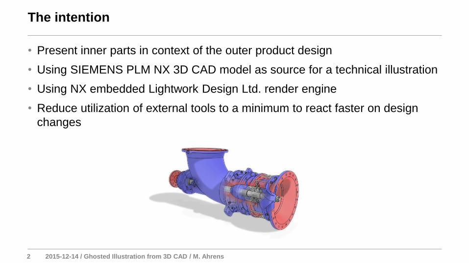
• Present inner parts in context of the outer product design
• Using SIEMENS PLM NX 3D CAD model as source for a technical illustration
• Using NX embedded Lightwork Design Ltd. render engine
• Reduce utilization of external tools to a minimum to react faster on design
changes
The intention
3 2015-12-14 / Ghosted Illustration from 3D CAD / M. Ahrens
• Identify components of interest
• Define a accurate camera for reuse
• Define (Section) views for the different levels of depth
• Set background
• Set lights
• Set floor
• Define Visualization Scene for synchronizing multiple Model Views
• Set resolution, size and quality for rendering process
• Render multiple passes of artistic images
• Compose final image in graphic tools (e.g. GIMP)
The process
4 2015-12-14 / Ghosted Illustration from 3D CAD / M. Ahrens
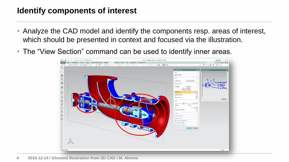
• Analyze the CAD model and identify the components resp. areas of interest,
which should be presented in context and focused via the illustration.
• The “View Section” command can be used to identify inner areas.
Identify components of interest
5 2015-12-14 / Ghosted Illustration from 3D CAD / M. Ahrens
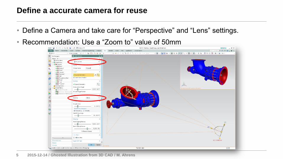
• Define a Camera and take care for “Perspective” and “Lens” settings.
• Recommendation: Use a “Zoom to” value of 50mm
Define a accurate camera for reuse
6 2015-12-14 / Ghosted Illustration from 3D CAD / M. Ahrens
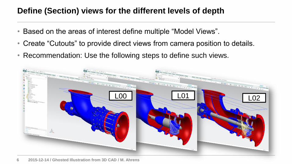
• Based on the areas of interest define multiple “Model Views”.
• Create “Cutouts” to provide direct views from camera position to details.
• Recommendation: Use the following steps to define such views.
Define (Section) views for the different levels of depth
L00 L01 L02
7 2015-12-14 / Ghosted Illustration from 3D CAD / M. Ahrens
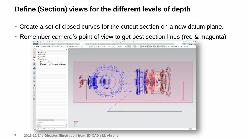
• Create a set of closed curves for the cutout section on a new datum plane.
• Remember camera’s point of view to get best section lines (red & magenta)
Define (Section) views for the different levels of depth
L00 L01 L02
8 2015-12-14 / Ghosted Illustration from 3D CAD / M. Ahrens
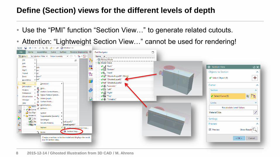
• Use the “PMI” function “Section View…” to generate related cutouts.
• Attention: “Lightweight Section View…” cannot be used for rendering!
Define (Section) views for the different levels of depth
9 2015-12-14 / Ghosted Illustration from 3D CAD / M. Ahrens
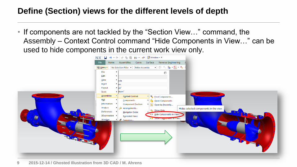
• If components are not tackled by the “Section View…” command, the
Assembly – Context Control command “Hide Components in View…” can be
used to hide components in the current work view only.
Define (Section) views for the different levels of depth
10 2015-12-14 / Ghosted Illustration from 3D CAD / M. Ahrens
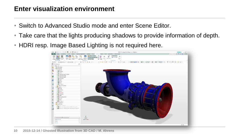
• Switch to Advanced Studio mode and enter Scene Editor.
• Take care that the lights producing shadows to provide information of depth.
• HDRI resp. Image Based Lighting is not required here.
Enter visualization environment
11 2015-12-14 / Ghosted Illustration from 3D CAD / M. Ahrens
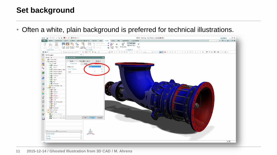
• Often a white, plain background is preferred for technical illustrations.
Set background
12 2015-12-14 / Ghosted Illustration from 3D CAD / M. Ahrens
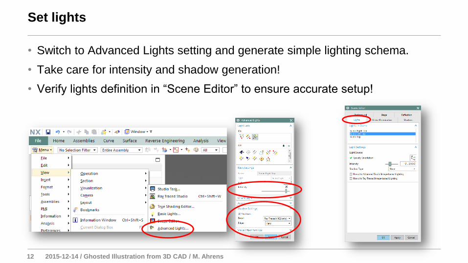
• Switch to Advanced Lights setting and generate simple lighting schema.
• Take care for intensity and shadow generation!
• Verify lights definition in “Scene Editor” to ensure accurate setup!
Set lights
13 2015-12-14 / Ghosted Illustration from 3D CAD / M. Ahrens
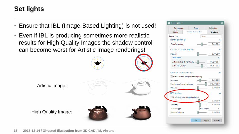
• Ensure that IBL (Image-Based Lighting) is not used!
• Even if IBL is producing sometimes more realistic
results for High Quality Images the shadow control
can become worst for Artistic Image renderings!
Set lights
Artistic Image:
High Quality Image:
14 2015-12-14 / Ghosted Illustration from 3D CAD / M. Ahrens
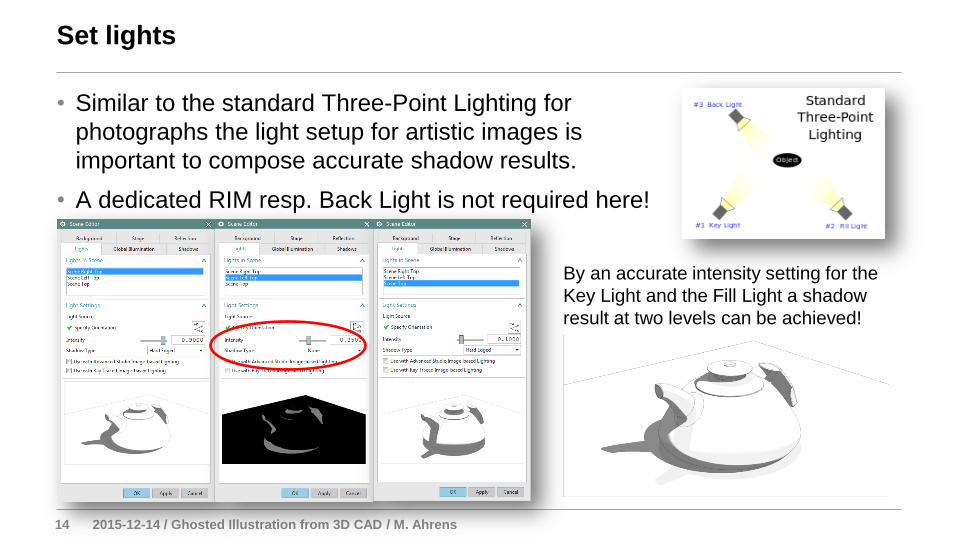
• Similar to the standard Three-Point Lighting for
photographs the light setup for artistic images is
important to compose accurate shadow results.
• A dedicated RIM resp. Back Light is not required here!
Set lights
By an accurate intensity setting for the
Key Light and the Fill Light a shadow
result at two levels can be achieved!
15 2015-12-14 / Ghosted Illustration from 3D CAD / M. Ahrens
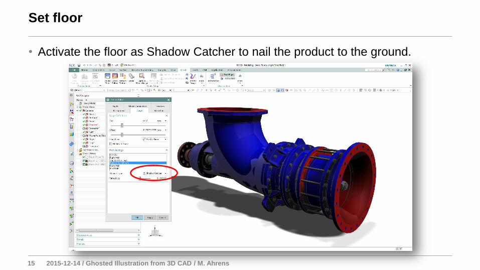
• Activate the floor as Shadow Catcher to nail the product to the ground.
Set floor
16 2015-12-14 / Ghosted Illustration from 3D CAD / M. Ahrens
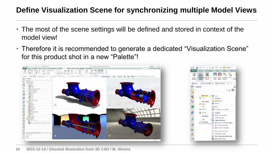
• The most of the scene settings will be defined and stored in context of the
model view!
• Therefore it is recommended to generate a dedicated “Visualization Scene”
for this product shot in a new “Palette”!
Define Visualization Scene for synchronizing multiple Model Views
17 2015-12-14 / Ghosted Illustration from 3D CAD / M. Ahrens
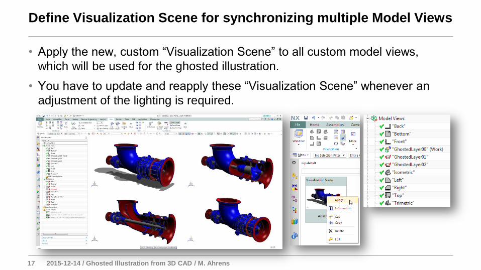
• Apply the new, custom “Visualization Scene” to all custom model views,
which will be used for the ghosted illustration.
• You have to update and reapply these “Visualization Scene” whenever an
adjustment of the lighting is required.
Define Visualization Scene for synchronizing multiple Model Views
18 2015-12-14 / Ghosted Illustration from 3D CAD / M. Ahrens
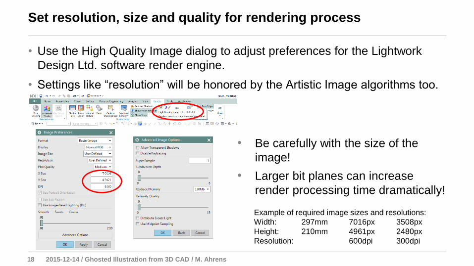
• Use the High Quality Image dialog to adjust preferences for the Lightwork
Design Ltd. software render engine.
• Settings like “resolution” will be honored by the Artistic Image algorithms too.
Set resolution, size and quality for rendering process
Example of required image sizes and resolutions:
Width: 297mm 7016px 3508px
Height: 210mm 4961px 2480px
Resolution: 600dpi 300dpi
• Be carefully with the size of the
image!
• Larger bit planes can increase
render processing time dramatically!
19 2015-12-14 / Ghosted Illustration from 3D CAD / M. Ahrens
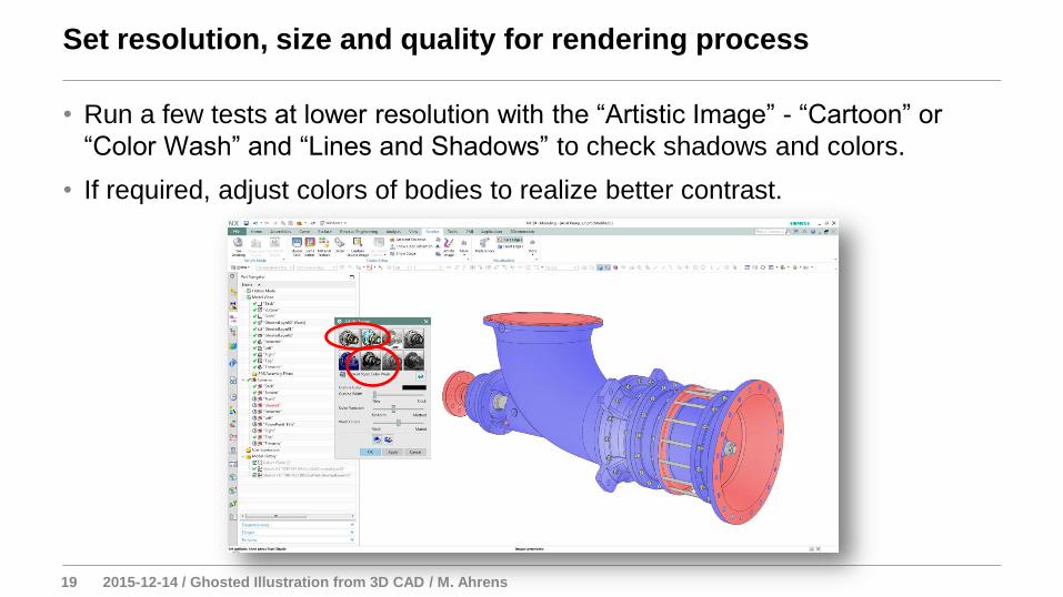
• Run a few tests at lower resolution with the “Artistic Image” - “Cartoon” or
“Color Wash” and “Lines and Shadows” to check shadows and colors.
• If required, adjust colors of bodies to realize better contrast.
Set resolution, size and quality for rendering process
20 2015-12-14 / Ghosted Illustration from 3D CAD / M. Ahrens
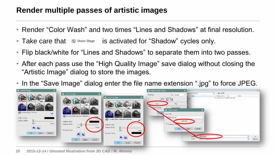
• Render “Color Wash” and two times “Lines and Shadows” at final resolution.
• Take care that is activated for “Shadow” cycles only.
• Flip black/white for “Lines and Shadows” to separate them into two passes.
• After each pass use the “High Quality Image” save dialog without closing the
“Artistic Image” dialog to store the images.
• In the “Save Image” dialog enter the file name extension “.jpg” to force JPEG.
Render multiple passes of artistic images
21 2015-12-14 / Ghosted Illustration from 3D CAD / M. Ahrens
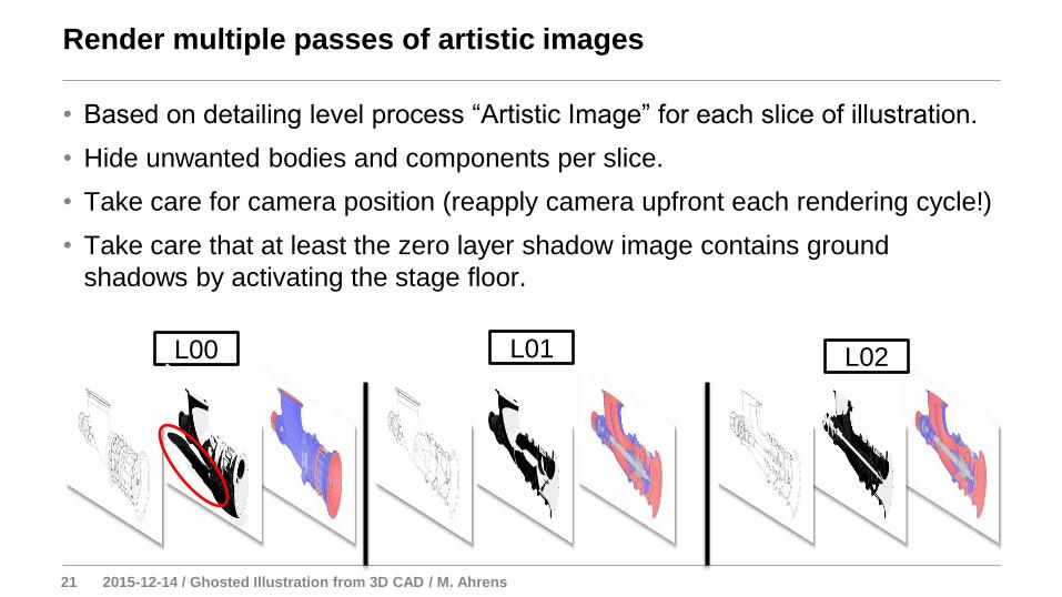
• Based on detailing level process “Artistic Image” for each slice of illustration.
• Hide unwanted bodies and components per slice.
• Take care for camera position (reapply camera upfront each rendering cycle!)
• Take care that at least the zero layer shadow image contains ground
shadows by activating the stage floor.
Render multiple passes of artistic images
L00 L01 L02
22 2015-12-14 / Ghosted Illustration from 3D CAD / M. Ahrens
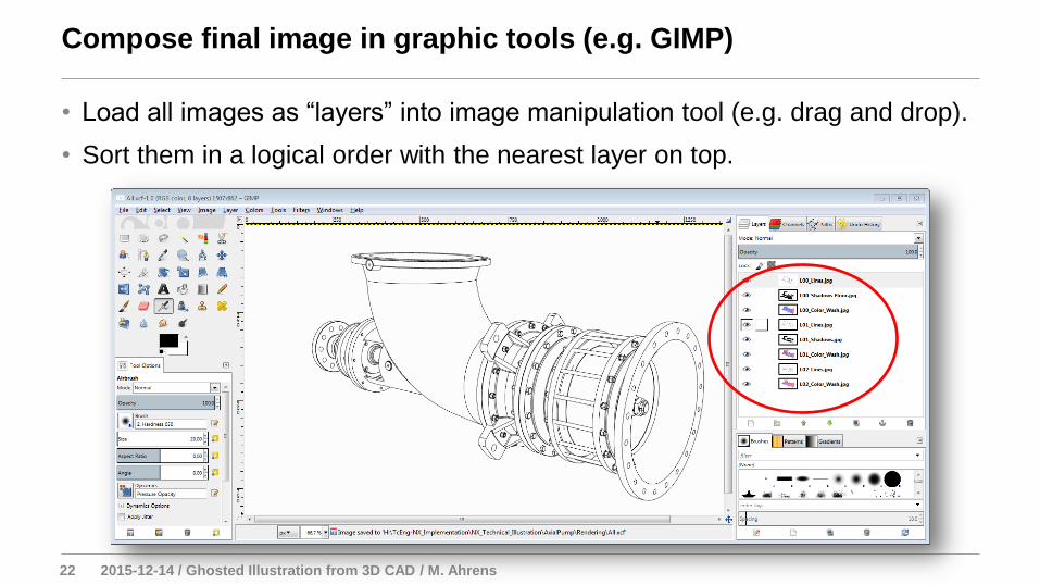
• Load all images as “layers” into image manipulation tool (e.g. drag and drop).
• Sort them in a logical order with the nearest layer on top.
Compose final image in graphic tools (e.g. GIMP)
23 2015-12-14 / Ghosted Illustration from 3D CAD / M. Ahrens
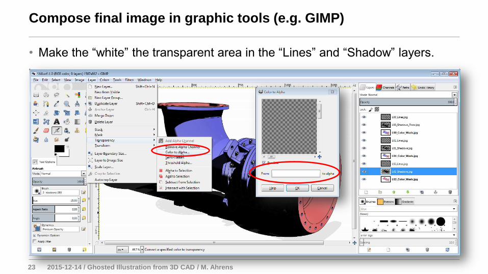
• Make the “white” the transparent area in the “Lines” and “Shadow” layers.
Compose final image in graphic tools (e.g. GIMP)
24 2015-12-14 / Ghosted Illustration from 3D CAD / M. Ahrens
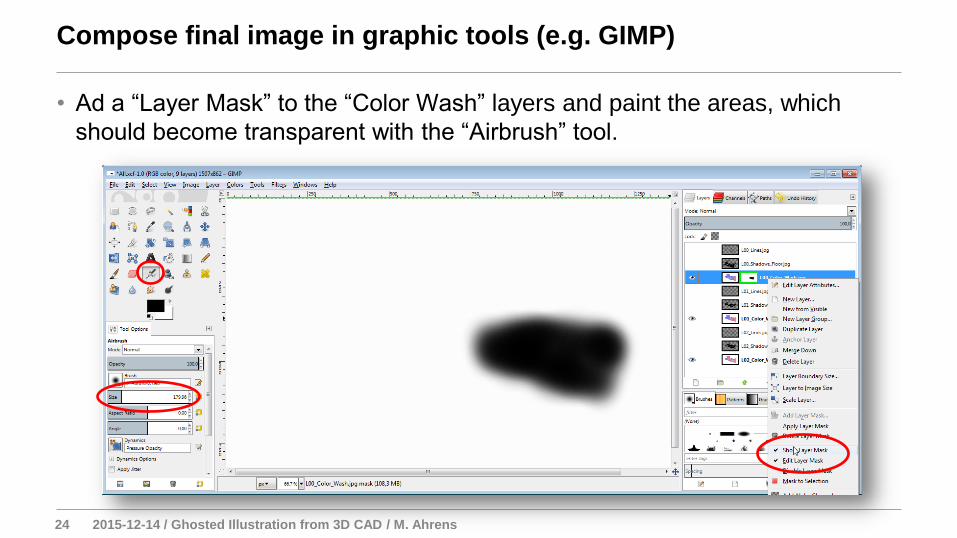
• Ad a “Layer Mask” to the “Color Wash” layers and paint the areas, which
should become transparent with the “Airbrush” tool.
Compose final image in graphic tools (e.g. GIMP)
25 2015-12-14 / Ghosted Illustration from 3D CAD / M. Ahrens
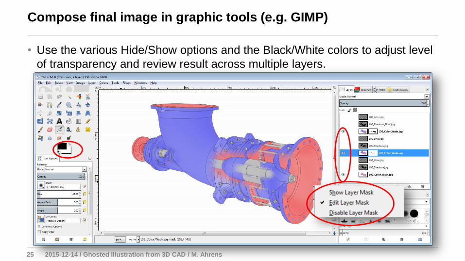
• Use the various Hide/Show options and the Black/White colors to adjust level
of transparency and review result across multiple layers.
Compose final image in graphic tools (e.g. GIMP)
26 2015-12-14 / Ghosted Illustration from 3D CAD / M. Ahrens
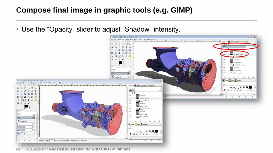
• Use the “Opacity” slider to adjust “Shadow” intensity.
Compose final image in graphic tools (e.g. GIMP)
27 2015-12-14 / Ghosted Illustration from 3D CAD / M. Ahrens
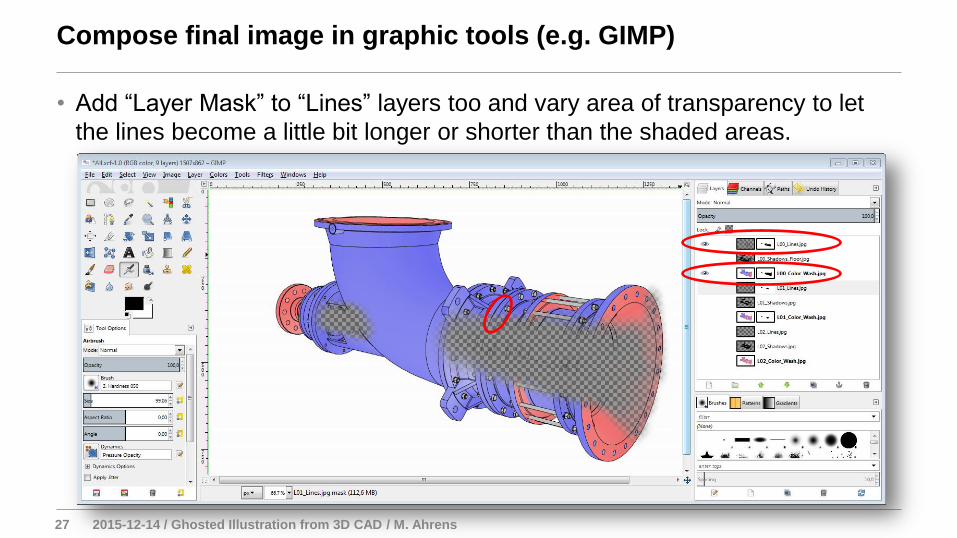
• Add “Layer Mask” to “Lines” layers too and vary area of transparency to let
the lines become a little bit longer or shorter than the shaded areas.
Compose final image in graphic tools (e.g. GIMP)
28 2015-12-14 / Ghosted Illustration from 3D CAD / M. Ahrens
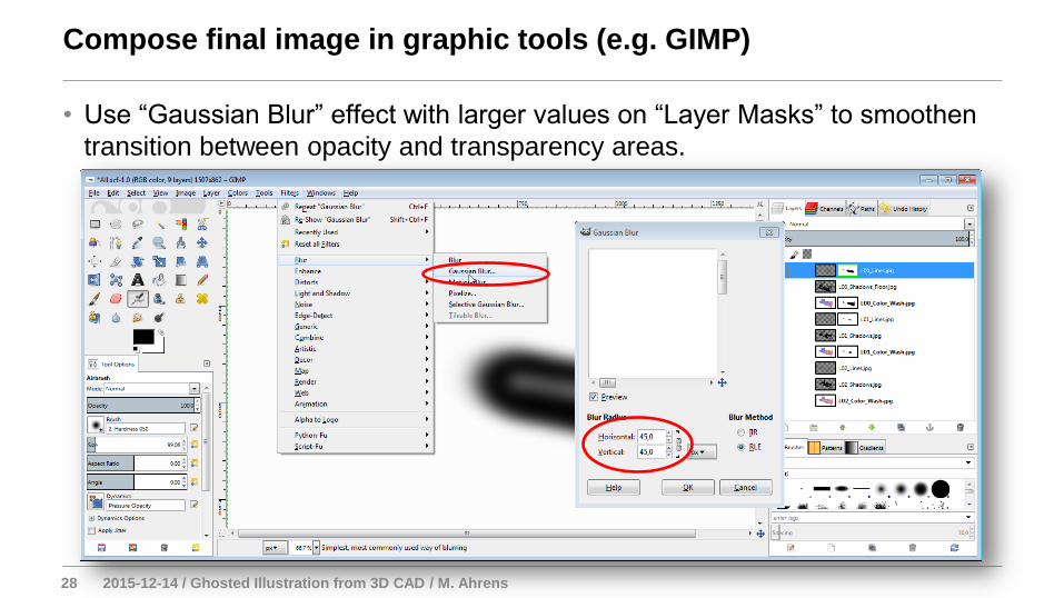
• Use “Gaussian Blur” effect with larger values on “Layer Masks” to smoothen
transition between opacity and transparency areas.
Compose final image in graphic tools (e.g. GIMP)
29 2015-12-14 / Ghosted Illustration from 3D CAD / M. Ahrens
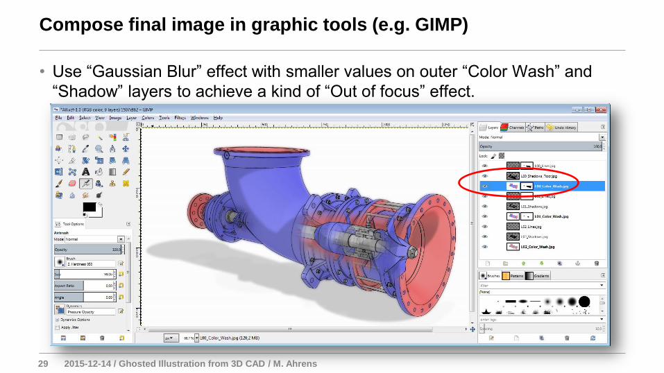
• Use “Gaussian Blur” effect with smaller values on outer “Color Wash” and
“Shadow” layers to achieve a kind of “Out of focus” effect.
Compose final image in graphic tools (e.g. GIMP)
30 2015-12-14 / Ghosted Illustration from 3D CAD / M. Ahrens
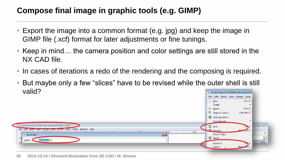
• Export the image into a common format (e.g. jpg) and keep the image in
GIMP file (.xcf) format for later adjustments or fine tunings.
• Keep in mind… the camera position and color settings are still stored in the
NX CAD file.
• In cases of iterations a redo of the rendering and the composing is required.
• But maybe only a few “slices” have to be revised while the outer shell is still
valid?
Compose final image in graphic tools (e.g. GIMP)
31 2015-12-14 / Ghosted Illustration from 3D CAD / M. Ahrens
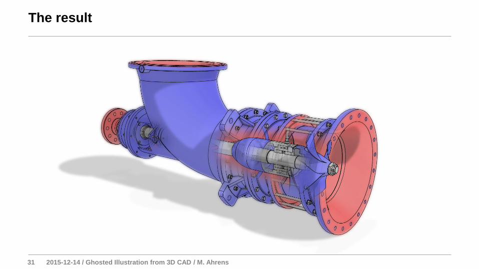
The result
32 2015-12-14 / Ghosted Illustration from 3D CAD / M. Ahrens
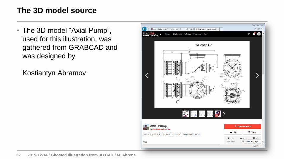
• The 3D model “Axial Pump”,
used for this illustration, was
gathered from GRABCAD and
was designed by
Kostiantyn Abramov
The 3D model source