Embed Size (px)
Citation preview
Page ii
Tabel Of Contents
TABEL OF CONTENTS ................................ ................................ .................... II
HYDRAULIC PUMPS ................................ ................................ ...................... 1
1-1 Introduction : .....................................................................................................................................................1
1-2 What are Pumps? ..............................................................................................................................................7
1-3 The main components of a pumping system are: ......................................................................................8
1-4 TYPE OF PUMPS: ..........................................................................................................................................8 1-4.1 Positive displacement pumps :........................................................................................................... 11 1-4.1.1 Rotary pumps :...................................................................................................................................... 11 1-4.1.2 Dynamic pumps: ................................................................................................................................... 13 1-4.2 Centrifugal Pumps: ............................................................................................................................... 14 1-4.3.1 Working Mechanism of the c entrifugal pump:............................................................................... 14 1-4.3.2 Centrifugal Pump Components ......................................................................................................... 14 1-4.3.3 Centrifugal Pump Classification:........................................................................................................ 25
1-5 PERFORMANCE CURV .................................................................................................................................... 26 1-5.1 Pumps in Series and Parallel: .............................................................................................................. 27
1-6 PUMP SEL ECTION: .......................................................................................................................................... 28
1-7 CAVITATION: ................................................................................................................................................... 30 1-7.1 Consideration of Cavitation ................................................................................................................ 30 1-7.2 Steps in Cavitation: ............................................................................................................................... 31 1-7.3 Net Positive Suction Head (NPSH) ..................................................................................................... 31 1-7.4 Methods to avoid Cavitaion:............................................................................................................... 32
1-8 Conclusions :.................................................................................................................................................... 33
Page iii
Tabel Of figers
FIGURE 1.1 PUMP IN SYSTEM................................ ................................ .......... 8
FIGURE 1.2 PUMP CLASSIFICATION................................ ................................ ..10
FIGURE 1.3 (PISTON PUMP) ................................ ................................ ...........12
FIGURE 1.4 (EXTERNAL GEAR PUMP ) ..................... ERROR! BOOKMARK NOT DEFINED.
FIGURE 1.5 (INTERNAL GEAR PUMP) ................................ ................................13
FIGURE1.6 (LOBE PUMP) ................................ .... ERROR! BOOKMARK NOT DEFINED.
FIGURE 1.7 (CENTRIFUGAL PUMP)......................... ERROR! BOOKMARK NOT DEFINED.
FIGURE 1.8 (CENTRIFUGAL PUMP COMPONENTS) ..... ERROR! BOOKMARK NOT DEFINED.
FIGURE 1.9 (ROTATING COMPONENTS )................................ ............................16
FIGURE 1.10 (OPEN IMPELLER) ................................ ................................ .......17
FIGURE 1.11(SEMI-OPEN IMPELLER) ................................ ................................17
FIGURE1.12 (ENCLOSED IMPELLER) ................................ ................................ .18
FIGURE1.13 ( SHAFT ) ................................ ................................ ..................18
FIGURE 1.14 (CUT-AWAY OF A PUMP SHOWING VOLUTE CASING) ...........................19
FIGURE 1.15 (CIRCULAR CASING) ................................ ................................ ....20
FIGURE 1.16 (WEARING RINGS )................................ ................................ ..21
FIGURE 1.17 (MECHANICAL SEAL) ......................... ERROR! BOOKMARK NOT DEFINED.
FIGURE 1.18 (SHAFT COUPLING) ........................... ERROR! BOOKMARK NOT DEFINED.
Page iv
FIGURE 1.19 (AXIAL FLOW CENTRIFUGAL PUMP) ................................ .................25
FIGURE 1.20 (RADIAL FLOW CENTRIFUGAL PUMP) ................................ ...............26
FIGURE 1.21 (MIXED FLOW CENTRIFUGAL PUMP) ................................ ...............26
FIGURE 1.21 (PUMP CURVE) ................................ ERROR! BOOKMARK NOT DEFINED.
FIGURE 1.22 (TWO PUMPS IN SERIES) .................... ERROR! BOOKMARK NOT DEFINED.
FIGURE 1.23 (TWO PUMPS IN PARALLEL) ................ ERROR! BOOKMARK NOT DEFINED.
FIGURE 1.24 (PUMP CAVITATION) ......................... ERROR! BOOKMARK NOT DEFINED.
FIGURE 1.25 (PUMP CAVITATION) ......................... ERROR! BOOKMARK NOT DEFINED.
Page 1
Hydraulic pumps
1-1 Introduction :
Page 2
Head lines
Why we choose this project ?
Important of Pumps in our life
Definition of pumps
Types of pumps
Working Principle of Pumps
Components of pumps
selection of pumpsMajor aspects in the
Performance curves
Pump Power and Efficiency
Centrifugal pumps design and dimensions standards
Pumps in our life
Page 3
Why we choose this project?
Every one know the important of pumps and how we use it in any place for many applications .
The transfer of liquids against gravity existed from time immemorial a few thousand yearsَوجدَ منذ األزل. A
pump is one such device that expends energy to raise,
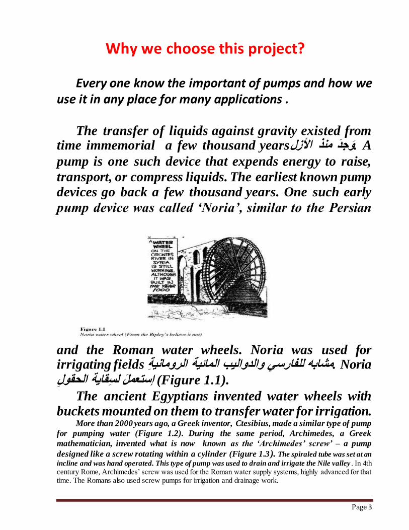
transport, or compress liquids. The earliest known pump devices go back a few thousand years. One such early
pump device was called ‘Noria’, similar to the Persian
and the Roman water wheels. Noria was used for irrigating fields مشابه للفارسي والدواليب المائية الرومانية. Noria
قاية الحقول .(Figure 1.1) إستعمَل لس
The ancient Egyptians invented water wheels with buckets mounted on them to transfer water for irrigation.
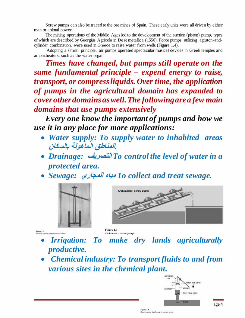
More than 2000 years ago, a Greek inventor, Ctesibius, made a similar type of pump
for pumping water (Figure 1.2). During the same period, Archimedes, a Greek
mathematician, invented what is now known as the ‘Archimedes’ screw’ – a pump
designed like a screw rotating within a cylinder (Figure 1.3). The spiraled tube was set at an
incline and was hand operated. This type of pump was used to drain and irrigate the Nile valley . In 4th century Rome, Archimedes’ screw was used for the Roman water supply systems, highly advanced for that time. The Romans also used screw pumps for irrigation and drainage work.
Page 4
Screw pumps can also be traced to the ore mines of Spain. These early units were all driven by either man or animal power.
The mining operations of the Middle Ages led to the development of the suction (piston) pump, types of which are described by Georgius Agricola in De re metallica (1556). Force pumps, utilizing a piston-and-cylinder combination, were used in Greece to raise water from wells (Figure 1.4).
Adopting a similar principle, air pumps operated spectacular musical devices in Greek temples and amphitheaters, such as the water organ.
Times have changed, but pumps still operate on the same fundamental principle – expend energy to raise,
transport, or compress liquids. Over time, the application
of pumps in the agricultural domain has expanded to cover other domains as well. The following are a few main
domains that use pumps extensively
Every one know the important of pumps and how we use it in any place for more applications:
Water supply: To supply water to inhabited areas .المناطق الماهولة بالسكان
Drainage: التصريف To control the level of water in a
protected area.
Sewage: مياه المجاري To collect and treat sewage.
Irrigation: To make dry lands agriculturally
productive.
Chemical industry: To transport fluids to and from
various sites in the chemical plant.
Page 5
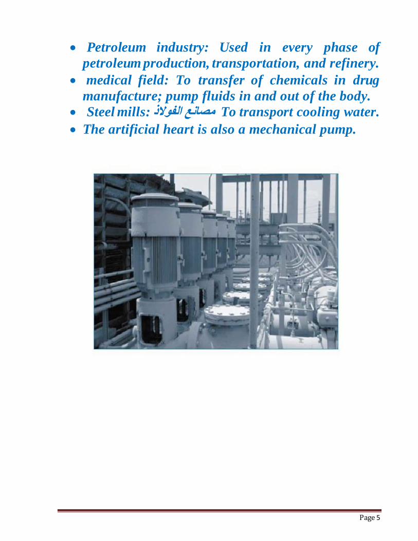
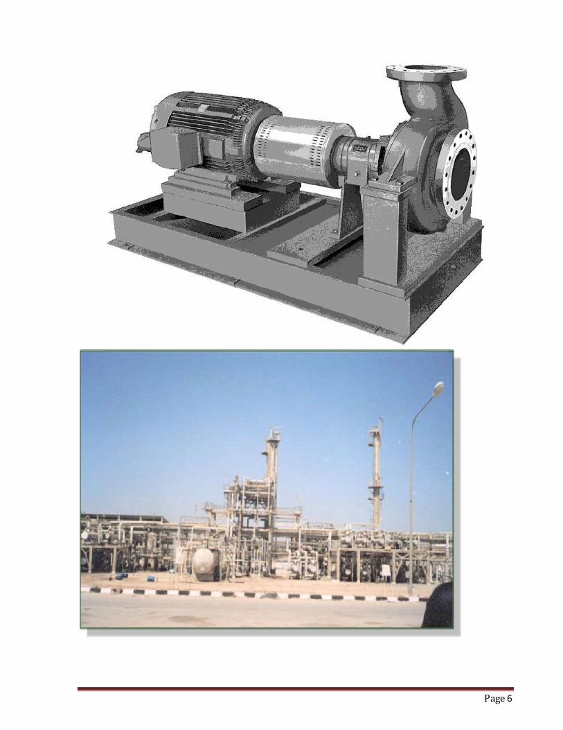
Petroleum industry: Used in every phase of
petroleum production, transportation, and refinery.
medical field: To transfer of chemicals in drug
manufacture; pump fluids in and out of the body.
Steel mills: مصانع الفوالذ To transport cooling water.
The artificial heart is also a mechanical pump.
Page 6
Page 7
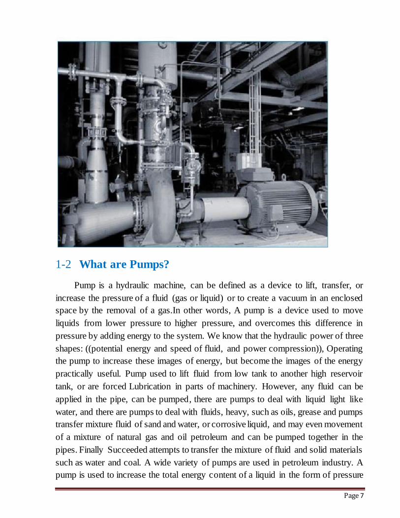
1-2 What are Pumps?
Pump is a hydraulic machine, can be defined as a device to lift, transfer, or
increase the pressure of a fluid (gas or liquid) or to create a vacuum in an enclosed
space by the removal of a gas.In other words, A pump is a device used to move
liquids from lower pressure to higher pressure, and overcomes this difference in
pressure by adding energy to the system. We know that the hydraulic power of three
shapes: ((potential energy and speed of fluid, and power compression)), Operating
the pump to increase these images of energy, but become the images of the energy
practically useful. Pump used to lift fluid from low tank to another high reservoir
tank, or are forced Lubrication in parts of machinery. However, any fluid can be
applied in the pipe, can be pumped, there are pumps to deal with liquid light like
water, and there are pumps to deal with fluids, heavy, such as oils, grease and pumps
transfer mixture fluid of sand and water, or corrosive liquid, and may even movement
of a mixture of natural gas and oil petroleum and can be pumped together in the
pipes. Finally Succeeded attempts to transfer the mixture of fluid and solid materials
such as water and coal. A wide variety of pumps are used in petroleum industry. A
pump is used to increase the total energy content of a liquid in the form of pressure
Page 8
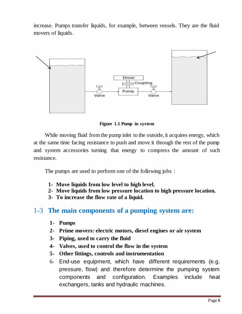
increase. Pumps transfer liquids, for example, between vessels. They are the fluid
movers of liquids.
Figure 1.1 Pump in system
While moving fluid from the pump inlet to the outside, it acquires energy, which
at the same time facing resistance to push and move it through the rest of the pump
and system accessories turning that energy to compress the amount of such
resistance.
The pumps are used to perform one of the following jobs :
1- Move liquids from low level to high level. 2- Move liquids from low pressure location to high pressure location.
3- To increase the flow rate of a liquid.
1-3 The main components of a pumping system are:
1- Pumps
2- Prime movers: electric motors, diesel engines or air system
3- Piping, used to carry the fluid
4- Valves, used to control the flow in the system
5- Other fittings, controls and instrumentation
6- End-use equipment, which have different requirements (e.g.
pressure, flow) and therefore determine the pumping system
components and configuration. Examples include heat
exchangers, tanks and hydraulic machines.
Page 9
1-4 TYPE OF PUMPS:
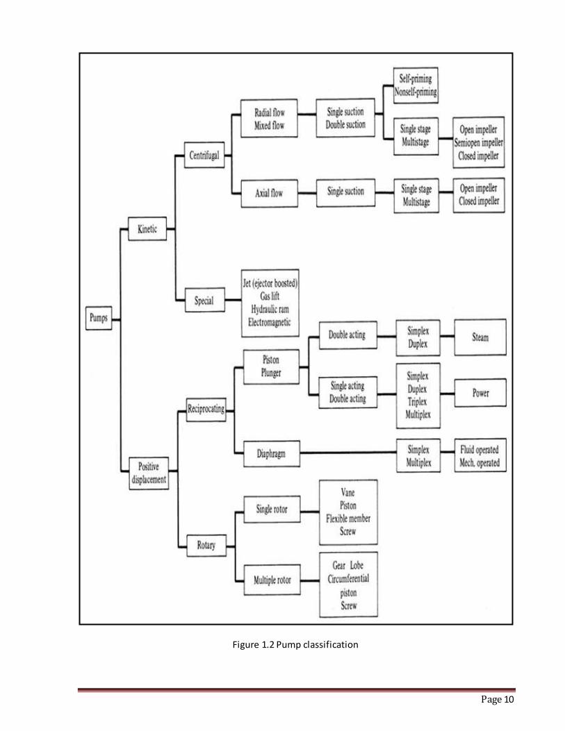
Pumps can be classified on various bases. Pumps are divided on the method to
add energy to the fluid. Pumps must have a mechanism which operates them, and
consume energy to perform mechanical work by moving the fluid. The activating
mechanism is often reciprocating or rotary. Pumps may be operated in many ways,
including manual operation, electricity, an engine of some type, or wind action.
Page 10
Figure 1.2 Pump classification
Page 11
1-4.1 Positive displacement pumps :
Liquid is taken from one end and positively discharged at the other end for every
revolution. Positive displacement pumps are widely used for pumping fluids other
than water, mostly viscous fluids.
Positive displacement pumps are further classified based upon the mode of
displacement :
1- Reciprocating pump if the displacement is by reciprocation of a
piston plunger. Reciprocating pumps are used only for pumping
viscous liquids and oil wells.
2- The liquid is being pumped is drawn into the cylinder through one
or more suction valves and then forced out through one or more
discharge valves by direct contact with the piston or plunger 3- The plunger reciprocates inside the stationary packing gland , the
packing gland prevents leakage from cylinder.
4- Reciprocating pumps have overall efficiency ranges from 50% for
the small capacity pumps to 90% for the larger capacity sizes.
1-4.1.1 Rotary pumps :
If the displacement is by rotary action of a gear, cam or vanes in a chamber of
diaphragm in a fixed casing. Rotary pumps are further classified such as gear, lobe
and slide vane etc. These pumps are used for special services with particular
conditions existing in industrial sites.
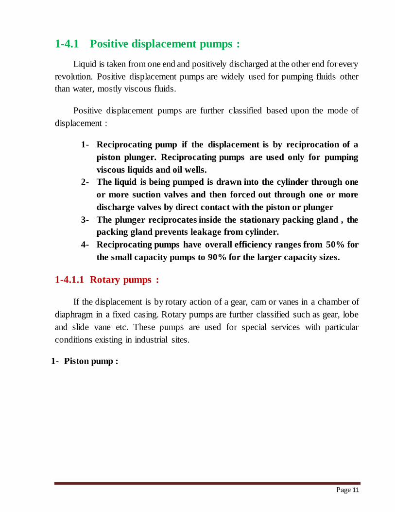
1- Piston pump :
Page 12
Figure 1.3 (Piston pump)
2- Rotary pump (Gear Pump) :
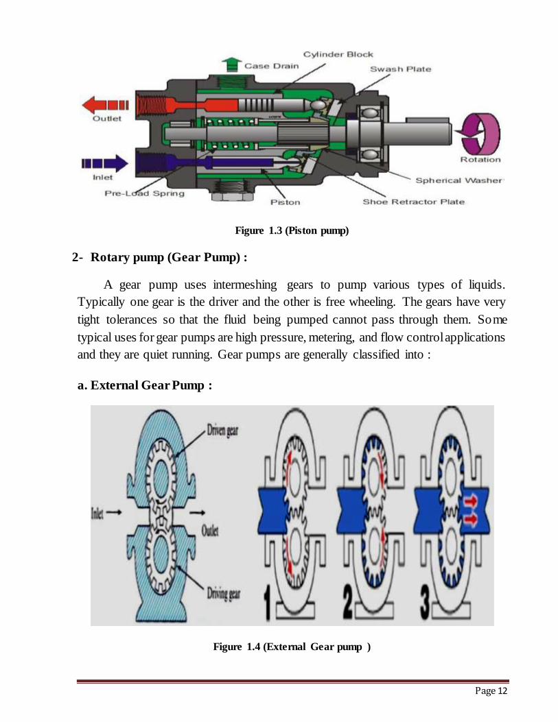
A gear pump uses intermeshing gears to pump various types of liquids.
Typically one gear is the driver and the other is free wheeling. The gears have very
tight tolerances so that the fluid being pumped cannot pass through them. Some
typical uses for gear pumps are high pressure, metering, and flow control applications
and they are quiet running. Gear pumps are generally classified into :
a. External Gear Pump :
Figure 1.4 (External Gear pump )
Page 13
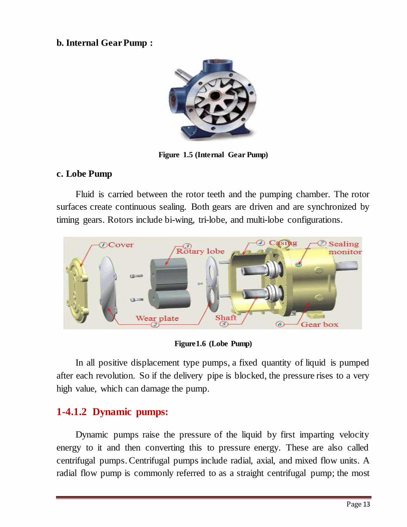
b. Internal Gear Pump :
Figure 1.5 (Internal Gear Pump)
c. Lobe Pump
Fluid is carried between the rotor teeth and the pumping chamber. The rotor
surfaces create continuous sealing. Both gears are driven and are synchronized by
timing gears. Rotors include bi-wing, tri-lobe, and multi-lobe configurations.
Figure1.6 (Lobe Pump)
In all positive displacement type pumps, a fixed quantity of liquid is pumped
after each revolution. So if the delivery pipe is blocked, the pressure rises to a very
high value, which can damage the pump.
1-4.1.2 Dynamic pumps:
Dynamic pumps raise the pressure of the liquid by first imparting velocity
energy to it and then converting this to pressure energy. These are also called
centrifugal pumps. Centrifugal pumps include radial, axial, and mixed flow units. A
radial flow pump is commonly referred to as a straight centrifugal pump; the most
Page 14
common type is the volute pump. Fluid enters the pump through the eye of impeller,
which rotates at high speed. The fluid is accelerated radically outward from the pump
casing. A partial vacuum is created that continuously draws more fluid into the pump
if properly primed. In the axial flow centrifugal pumps, the rotor is a propeller. Fluid
flows parallel to the axis of the shaft .The mixed flow-the direction of liquid from
the impeller acts as an in-between that of the radial and axial flow pumps.
1-4.2 Centrifugal Pumps:
The centrifugal pump is the most used pump type in the world, A centrifugal
pump is one of the simplest pieces of equipment in any process Plant ,Typically,
more than 15% of the pumps installed in an industry are centrifugal pumps. . Its
purpose is to convert energy of a prime mover (a electric motor or turbine) first into
velocity or kinetic energy and then into pressure energy of a fluid that is being
pumped.
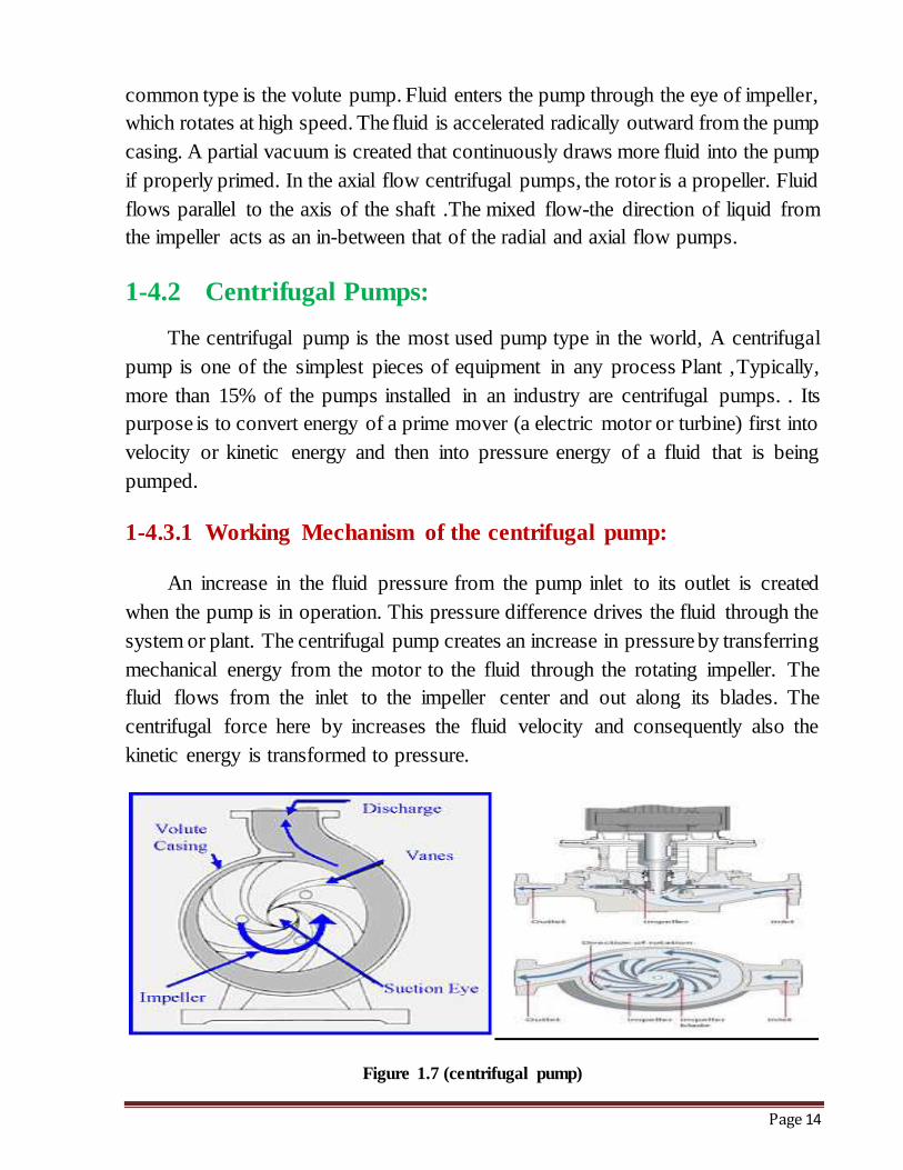
1-4.3.1 Working Mechanism of the centrifugal pump:
An increase in the fluid pressure from the pump inlet to its outlet is created
when the pump is in operation. This pressure difference drives the fluid through the
system or plant. The centrifugal pump creates an increase in pressure by transferring
mechanical energy from the motor to the fluid through the rotating impeller. The
fluid flows from the inlet to the impeller center and out along its blades. The
centrifugal force here by increases the fluid velocity and consequently also the
kinetic energy is transformed to pressure.
Figure 1.7 (centrifugal pump)
Page 15
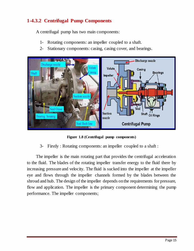
1-4.3.2 Centrifugal Pump Components
A centrifugal pump has two main components:
1- Rotating components: an impeller coupled to a shaft.
2- Stationary components: casing, casing cover, and bearings.
Figure 1.8 (Centrifugal pump components)
3- Firstly : Rotating components: an impeller coupled to a shaft :
The impeller is the main rotating part that provides the centrifugal acceleration
to the fluid. The blades of the rotating impeller transfer energy to the fluid there by
increasing pressure and velocity. The fluid is sucked into the impeller at the impeller
eye and flows through the impeller channels formed by the blades between the
shroud and hub. The design of the impeller depends on the requirements for pressure,
flow and application. The impeller is the primary component determining the pump
performance. The impeller components;
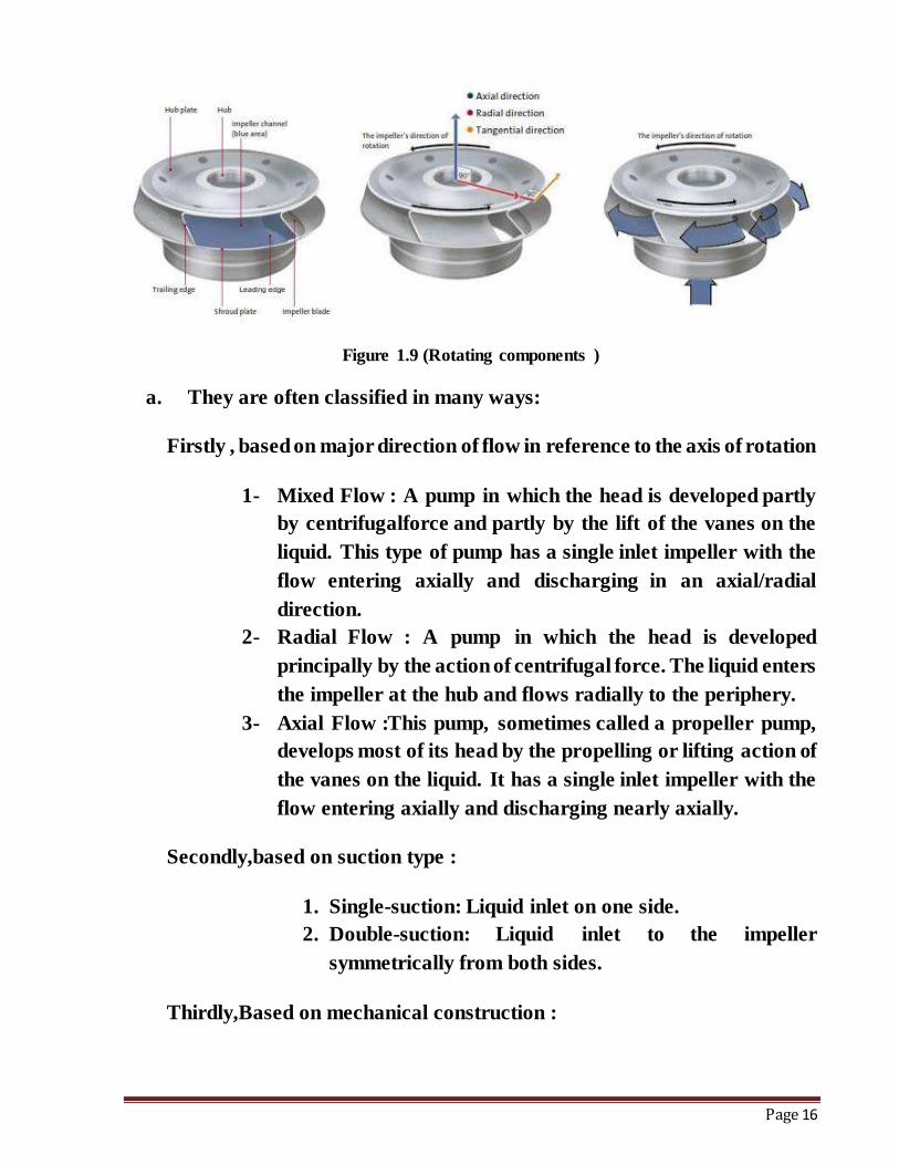
Page 16
Figure 1.9 (Rotating components )
a. They are often classified in many ways:
Firstly , based on major direction of flow in reference to the axis of rotation
1- Mixed Flow : A pump in which the head is developed partly
by centrifugalforce and partly by the lift of the vanes on the
liquid. This type of pump has a single inlet impeller with the
flow entering axially and discharging in an axial/radial
direction.
2- Radial Flow : A pump in which the head is developed
principally by the action of centrifugal force. The liquid enters
the impeller at the hub and flows radially to the periphery.
3- Axial Flow :This pump, sometimes called a propeller pump,
develops most of its head by the propelling or lifting action of
the vanes on the liquid. It has a single inlet impeller with the
flow entering axially and discharging nearly axially.
Secondly,based on suction type :
1. Single-suction: Liquid inlet on one side.
2. Double-suction: Liquid inlet to the impeller
symmetrically from both sides.
Thirdly,Based on mechanical construction :
Page 17
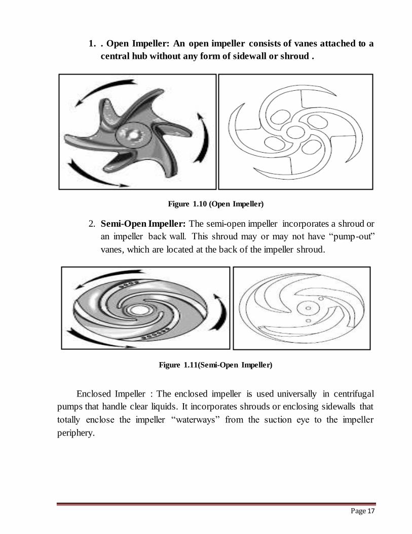
1. . Open Impeller: An open impeller consists of vanes attached to a
central hub without any form of sidewall or shroud .
Figure 1.10 (Open Impeller)
2. Semi-Open Impeller: The semi-open impeller incorporates a shroud or
an impeller back wall. This shroud may or may not have “pump-out”
vanes, which are located at the back of the impeller shroud.
Figure 1.11(Semi-Open Impeller)
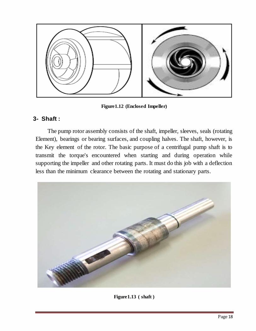
Enclosed Impeller : The enclosed impeller is used universally in centrifugal
pumps that handle clear liquids. It incorporates shrouds or enclosing sidewalls that
totally enclose the impeller “waterways” from the suction eye to the impeller
periphery.
Page 18
Figure1.12 (Enclosed Impeller)
3- Shaft :
The pump rotor assembly consists of the shaft, impeller, sleeves, seals (rotating
Element), bearings or bearing surfaces, and coupling halves. The shaft, however, is
the Key element of the rotor. The basic purpose of a centrifugal pump shaft is to
transmit the torque's encountered when starting and during operation while
supporting the impeller and other rotating parts. It must do this job with a deflection
less than the minimum clearance between the rotating and stationary parts.
Figure1.13 ( shaft )
Page 19
4- Casing:
Casings are generally of two types are volute and circular. The impellers are
fitted inside the casings.
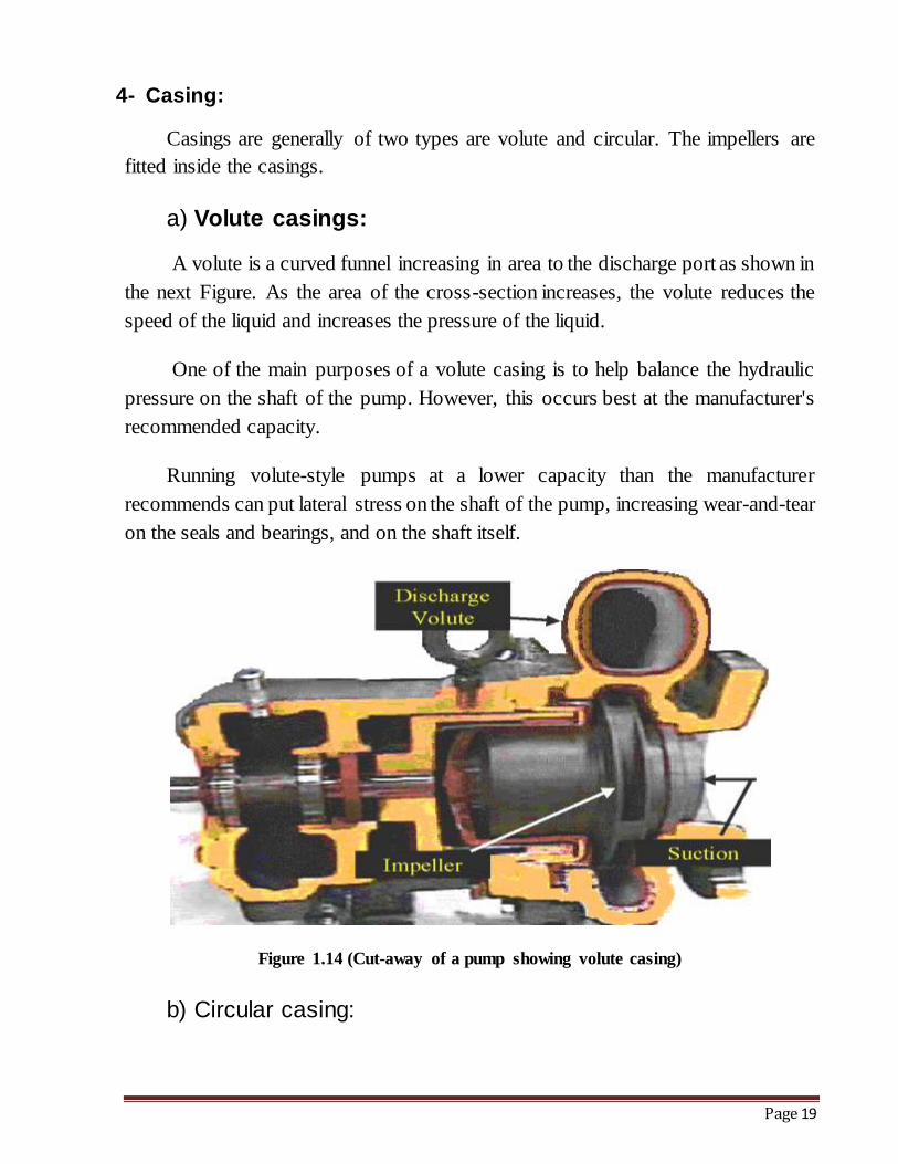
a) Volute casings:
A volute is a curved funnel increasing in area to the discharge port as shown in
the next Figure. As the area of the cross-section increases, the volute reduces the
speed of the liquid and increases the pressure of the liquid.
One of the main purposes of a volute casing is to help balance the hydraulic
pressure on the shaft of the pump. However, this occurs best at the manufacturer's
recommended capacity.
Running volute-style pumps at a lower capacity than the manufacturer
recommends can put lateral stress on the shaft of the pump, increasing wear-and-tear
on the seals and bearings, and on the shaft itself.
Figure 1.14 (Cut-away of a pump showing volute casing)
b) Circular casing:
Page 20
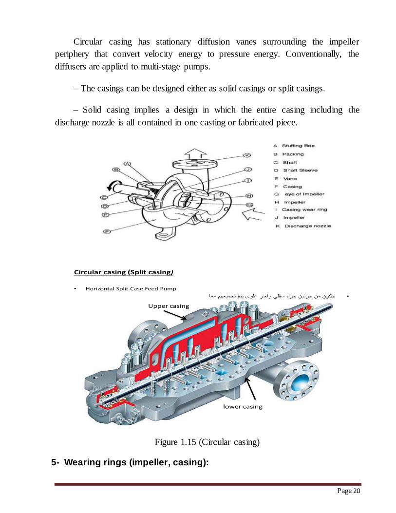
Circular casing has stationary diffusion vanes surrounding the impeller
periphery that convert velocity energy to pressure energy. Conventionally, the
diffusers are applied to multi-stage pumps.
– The casings can be designed either as solid casings or split casings.
– Solid casing implies a design in which the entire casing including the
discharge nozzle is all contained in one casting or fabricated piece.
)casing (Split casingCircular
• Horizontal Split Case Feed Pump
•
Upper casing
lower casing
Figure 1.15 (Circular casing)
5- Wearing rings (impeller, casing):
Page 21
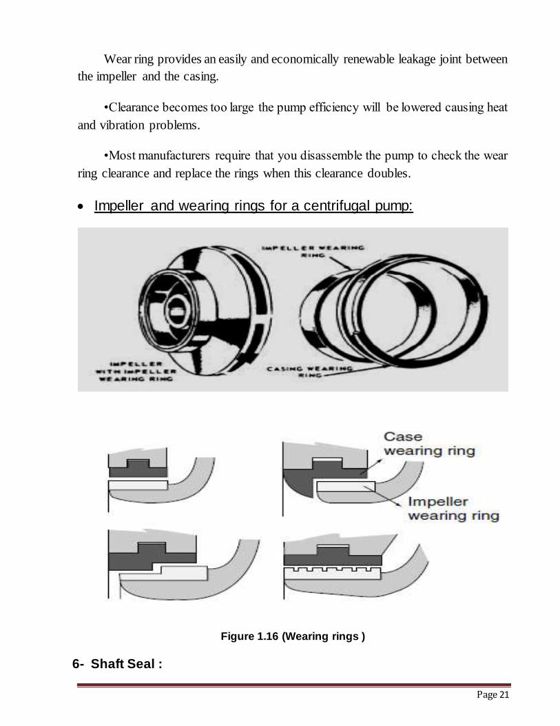
Wear ring provides an easily and economically renewable leakage joint between
the impeller and the casing.
•Clearance becomes too large the pump efficiency will be lowered causing heat
and vibration problems.
•Most manufacturers require that you disassemble the pump to check the wear
ring clearance and replace the rings when this clearance doubles.
Impeller and wearing rings for a centrifugal pump:
Figure 1.16 (Wearing rings )
6- Shaft Seal :
Page 22
a. Description:-
Centrifugal and rotary positive displacement pumps require controlling of the
pumped fluids desire to exit through the stuffing box, the area where the pump shaft
enters the pump fluid end. When operating the pumped fluid within The stuffing box
sees a pressure higher than the surrounding atmospheric pressure, the fluid coming
from this side (stuffing box ), So we need shaft seal to prevent the leakage or reduce
it .
b. Purpose of use shaft seals
1- To prevent leakage
2- To reduce vibration
3- To reduce rotating friction and corrosion of the pump shaft
c. Type of shaft seals
1- Packing ring.
2- Mechanical Seal.
Firstly-Packing ring (for Centrifugal pump)
1.1)-Stuffing box.
The stuffing box is a chamber or a housing that serves to seal the shaft where it
passes through the pump casing.
1.B) -Packed Plunger Pumps and Piston Pumps
In these pumps, a reciprocating piston (plunger) moves fluid through a chamber
by creating alternate suction and pressure conditions. One-way check valves on the
inlet and outlet ports of the pump operate 180° out of phase in order to control filling
of the displacement chamber during suction and to prevent backflow during the
discharge stroke, we used packing to prevent leakage from high pressure side to
atmosphere.
secondly : Mechanical Seal :
Page 23
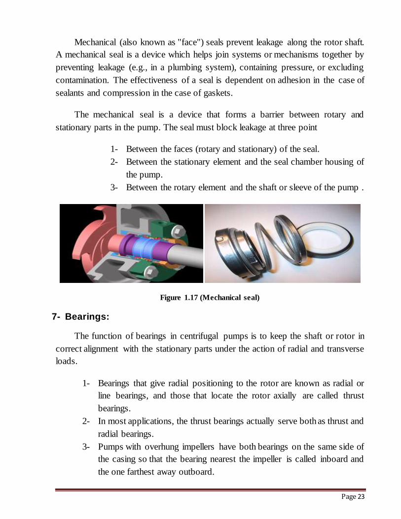
Mechanical (also known as "face") seals prevent leakage along the rotor shaft.
A mechanical seal is a device which helps join systems or mechanisms together by
preventing leakage (e.g., in a plumbing system), containing pressure, or excluding
contamination. The effectiveness of a seal is dependent on adhesion in the case of
sealants and compression in the case of gaskets.
The mechanical seal is a device that forms a barrier between rotary and
stationary parts in the pump. The seal must block leakage at three point
1- Between the faces (rotary and stationary) of the seal.
2- Between the stationary element and the seal chamber housing of
the pump.
3- Between the rotary element and the shaft or sleeve of the pump .
Figure 1.17 (Mechanical seal)
7- Bearings:
The function of bearings in centrifugal pumps is to keep the shaft or rotor in
correct alignment with the stationary parts under the action of radial and transverse
loads.
1- Bearings that give radial positioning to the rotor are known as radial or
line bearings, and those that locate the rotor axially are called thrust
bearings.
2- In most applications, the thrust bearings actually serve both as thrust and
radial bearings.
3- Pumps with overhung impellers have both bearings on the same side of
the casing so that the bearing nearest the impeller is called inboard and
the one farthest away outboard.
Page 24
4- By The bearings are mounted in a housing that is usually supported
brackets attached or integral to the pump casing.
Bearing housing:
1. The bearing housing encloses the bearings mounted on the shaft. The bearings keep the shaft or rotor in correct alignment with the stationary
parts under the action of radial and transverse loads. The bearing house also includes an oil reservoir for lubrication, constant level oiler, jacket for cooling by circulating cooling water.
2. The housing also serves the function of containing the lubricant necessary for proper operation of the bearing.
1- Coupling:
Couplings can compensate for axial growth of the shaft and transmit torque to
the impeller. Shaft couplings can be broadly classified into two groups: (rigid and
flexible).
Rigid couplings are used in applications where there is absolutely no possibility
or room for any misalignment.
Flexible shaft couplings are more prone to selection, installation and
maintenance errors. Flexible shaft couplings can be divided into two basic groups:
(elastomeric and non-elastomeric).
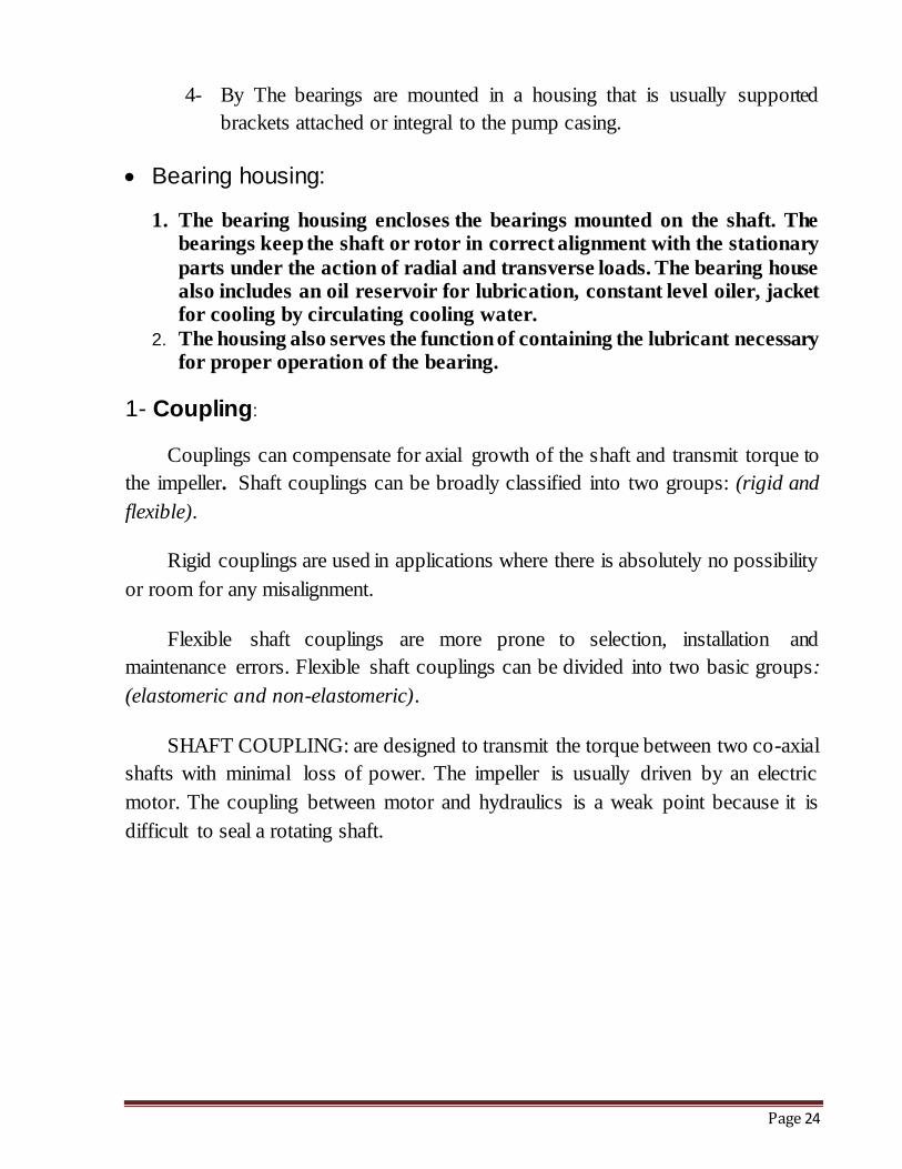
SHAFT COUPLING: are designed to transmit the torque between two co-axial
shafts with minimal loss of power. The impeller is usually driven by an electric
motor. The coupling between motor and hydraulics is a weak point because it is
difficult to seal a rotating shaft.
Page 25
Figure 1.18 (SHAFT COUPLING)
1-4.3.3 Centrifugal Pump Classification:
1- Centrifugal pumps can be classified based on the manner in which fluid
flows through the pump.
2- The manner in which fluid flows through the pump is determined by the
design of the pump casing and the impeller.
3- The three types of flow through a centrifugal pump are:
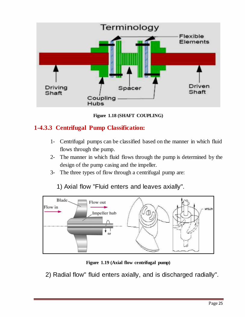
1) Axial flow "Fluid enters and leaves axially".
Figure 1.19 (Axial flow centrifugal pump)
2) Radial flow" fluid enters axially, and is discharged radially".
Page 26
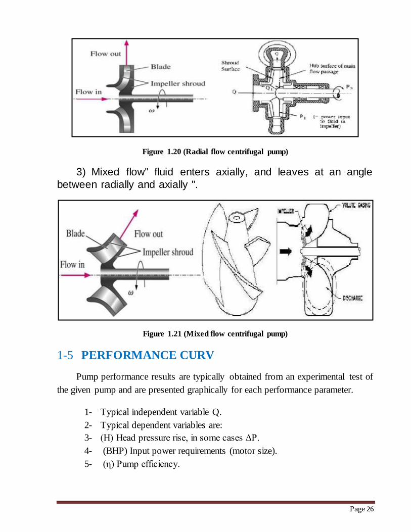
Figure 1.20 (Radial flow centrifugal pump)
3) Mixed flow" fluid enters axially, and leaves at an angle
between radially and axially ".
Figure 1.21 (Mixed flow centrifugal pump)
1-5 PERFORMANCE CURV
Pump performance results are typically obtained from an experimental test of
the given pump and are presented graphically for each performance parameter.
1- Typical independent variable Q.
2- Typical dependent variables are:
3- (H) Head pressure rise, in some cases ΔP.
4- (BHP) Input power requirements (motor size).
5- (η) Pump efficiency.
Page 27
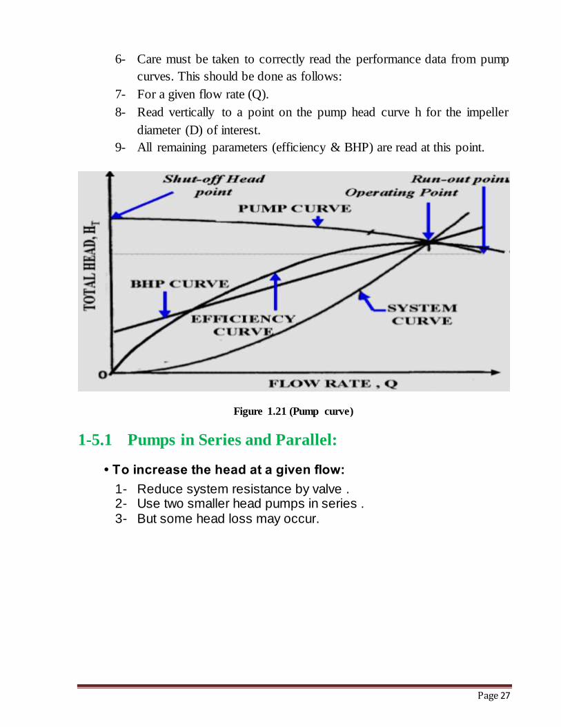
6- Care must be taken to correctly read the performance data from pump
curves. This should be done as follows:
7- For a given flow rate (Q).
8- Read vertically to a point on the pump head curve h for the impeller
diameter (D) of interest.
9- All remaining parameters (efficiency & BHP) are read at this point.
Figure 1.21 (Pump curve)
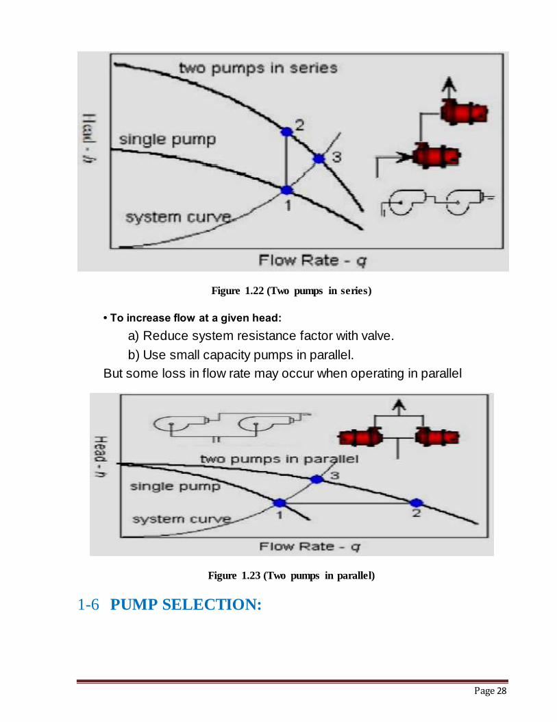
1-5.1 Pumps in Series and Parallel:
• To increase the head at a given flow:
1- Reduce system resistance by valve . 2- Use two smaller head pumps in series . 3- But some head loss may occur.
Page 28
Figure 1.22 (Two pumps in series)
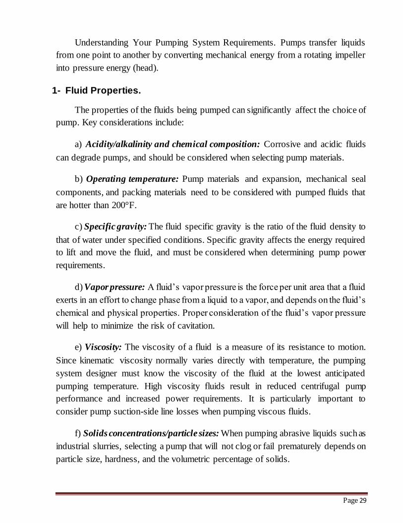
• To increase flow at a given head:
a) Reduce system resistance factor with valve.
b) Use small capacity pumps in parallel.
But some loss in flow rate may occur when operating in parallel
Figure 1.23 (Two pumps in parallel)
1-6 PUMP SELECTION:
Page 29
Understanding Your Pumping System Requirements. Pumps transfer liquids
from one point to another by converting mechanical energy from a rotating impeller
into pressure energy (head).
1- Fluid Properties.
The properties of the fluids being pumped can significantly affect the choice of
pump. Key considerations include:
a) Acidity/alkalinity and chemical composition: Corrosive and acidic fluids
can degrade pumps, and should be considered when selecting pump materials.
b) Operating temperature: Pump materials and expansion, mechanical seal
components, and packing materials need to be considered with pumped fluids that
are hotter than 200°F.
c) Specific gravity: The fluid specific gravity is the ratio of the fluid density to
that of water under specified conditions. Specific gravity affects the energy required
to lift and move the fluid, and must be considered when determining pump power
requirements.
d) Vapor pressure: A fluid’s vapor pressure is the force per unit area that a fluid
exerts in an effort to change phase from a liquid to a vapor, and depends on the fluid’s
chemical and physical properties. Proper consideration of the fluid’s vapor pressure
will help to minimize the risk of cavitation.
e) Viscosity: The viscosity of a fluid is a measure of its resistance to motion.
Since kinematic viscosity normally varies directly with temperature, the pumping
system designer must know the viscosity of the fluid at the lowest anticipated
pumping temperature. High viscosity fluids result in reduced centrifugal pump
performance and increased power requirements. It is particularly important to
consider pump suction-side line losses when pumping viscous fluids.
f) Solids concentrations/particle sizes: When pumping abrasive liquids such as
industrial slurries, selecting a pump that will not clog or fail prematurely depends on
particle size, hardness, and the volumetric percentage of solids.
Page 30
2- Environmental Considerations :
Important environmental considerations include ambient temperature and
humidity, elevation above sea level, and whether the pump is to be installed indoors
or outdoors.
3- Software Tools :
Most pump manufacturers have developed software or Web-based tools to
assist in the pump selection process. Pump purchasers enter their fluid properties and
system requirements to obtain a listing of suitable pumps. Software tools that allow
you to evaluate and compare operating costs are available from private vendors.
4- The Cost.
1-7 CAVITATION:
CAVITATION : Knocking due to formation and subsequent collapse of vapor
bubbles. (Indication: Noise), and caused by the formation of vapor bubbles in a high-
velocity, low-pressure region and by the subsequent collapse when the bubbles move
to a higher pressure region. Cavitation can cause excessive erosion and vibration.
Pump cavitation is a potential danger when pumps operate at high speeds and
at a capacity greater than the best efficiency point. Cavitation reduces pump capacity
and efficiency and can damage the pump. It occurs in the pump when the absolute
pressure of the inlet drops below the vapor pressure of the fluid being pumped. Under
this condition, vapor bubbles form at the inlet and, when the vapor bubbles are
carried into a high pressure zone, they collapse abruptly. The surrounding fluid
rushes to fill the void with such force that a hammering action occurs. The high
localized stresses that result from the hammering action can pit the pump impeller.
The blades have been pitted and scarred as a result of cavitation.
1-7.1 Consideration of Cavitation
Cavitation occurs when NPSHr is larger than NPSHa. Cavitation reduces the
performance of pump, causes vibration or noise and corrodes the materials. High
pump-suction velocities and long piping increase pressure fluctuations in the pump.
Page 31
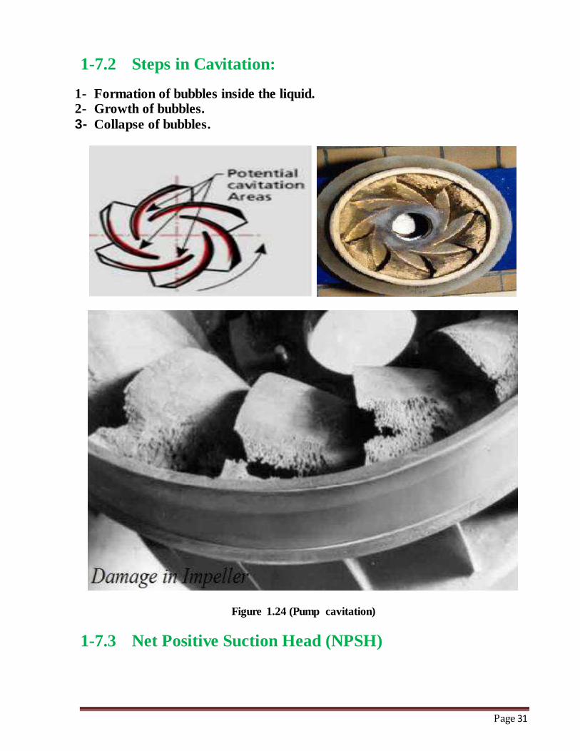
1-7.2 Steps in Cavitation:
1- Formation of bubbles inside the liquid. 2- Growth of bubbles.
3- Collapse of bubbles.
Figure 1.24 (Pump cavitation)
1-7.3 Net Positive Suction Head (NPSH)
Page 32
The net positive suction head (NPSH) is the absolute pressure in excess of the
liquid vapor pressure that is available at the pump suction nozzle to move the liquid
into the eye of the impeller.
The difference between NPSHa and NPSHr is less than 0.3 ∼ 1.0m at the time
of checking vendor data sheet [ that is, NPSHa¬ NPSHr〈 (0.3 ∼ 1m)], decision
on NPSH test shall be made according to Engineering Specification SES-GA-201E
and API 610.
Pumps where difference between NPSHA and NPSHR is less than 0.6 meter
are not acceptable.
The diameter of the pump suction port is usually bigger than the discharge or
exit diameter in order to minimize the kinetic energy head entering the pump,
because this kinetic energy decreases the maximum suction lift and enhances
cavitation
NPSH can be defined as two parts:
1- NPSH Available (NPSHA): The absolute pressure at the suction port of the pump.
2- NPSH Required (NPSHR): The minimum pressure required at the suction port of the pump to keep the pump from cavitation.
NPSHA is a function of your system and must be calculated, whereas NPSHR
is a function of the pump and must be provided by the pump manufacturer. NPSHA
must be greater than NPSHR for the pump system to operate without cavitation. Put
another way, you must have more suction side pressure available than the pump
requires.
1-7.4 Methods to avoid Cavitaion:
NPSHa (P(suction) - P(saturation) >= NPSHr Increase NPSHa by
1- Increase pressure at suction of pump
2- Decrease liquid temperature
3- Reduce head losses
Page 33
4- Reduce NPSHr (Depends on Impeller inlet, Impeller design, Pump
flow rate, impeller speed, type of liquid).
1-8 Conclusions :
1- Pumps are basic element in any system.
2- There are many types of Pumps but the main type is centrifugal pump, where it is widely used for lift water from low level to high level.
3- Centrifugal Pumps in steam power plant used as for lift water from low level
to high level (Boiler) and Positive displacement pumps for turbine shaft cooling and moving fluid to combustion chambers.
4- We must be attention to the pressure inlet pump to avoid cavitation. 5- We must be carefully when choosing or make selection on the pump.
6- Maintenance must be done periodically at the pumps to make sure work correctly.
7- We must put Pump as stand by if there is a sudden failure of any pump station so as not to stop.