Embed Size (px)
Citation preview
International Journal on Recent and Innovation Trends in Computing and Communication ISSN: 2321-8169
Volume: 4 Issue: 5 105 - 111
____________________________________________________________________________________________________________________
105
IJRITCC | May 2016, Available @ http://www.ijritcc.org
_______________________________________________________________________________________________________
Image Compression Using Hybrid(DCT+DWT) Technique- A Comparative
Study
Asjah Ul Ain1 and Supriya Khaitan
2
Sharda School of Engineering and Technology
Sharda University Uttar Pradesh ,Greater Noida U.P
Email: [email protected] , [email protected]
Abstract— When the data is in uncompressed state it becomes difficult to store and transmit it. This problem can be addressed by image
compression. Image compression reduces the number of bits per pixel of the image so that its storage and transmission becomes easy. Basic goal
of image compression is to increase visual quality of image with less noise. The proposed methodology satisfies this aim. Hybrid of DCT
(Discrete Cosine Transformation) and DWT (Discrete Wavelet Transformation) are combined to achieve this goal. Combined advantages of
DCT and DWT are used as proposed methodology. DCT has high energy compaction and less number of computational resources are required
while DWT has multi resolution transformation. Hybrid DCT-DWT is proposed to compress and reconstruct images. Also colorization of the
reconstructed images is proposed. Reconstructed images are stored in gray format and to visualize it colorization is done on that gray scale
image. Results show that this method of compression and colorization helps in compressing and retaining color of images.
Keywords— Compression, DCT, DWT, hybrid wavelet transformation (DCT+DWT), clustering, Mean Square Error (MSE), PSNR
__________________________________________________*****_________________________________________________
1. Introduction Uncompressed images occupy more space in system
memory and uses more bandwidth while transmission. So, compression of images has become need as it takes less space and requires less bandwidth. Compression of images means to hide the detailed part of images and show only the approximation part of images or represent images in their compact form. Compression helps in managing and transmitting images files easily. Image compression is divided into two basic categories lossy and lossless compression. In lossy image compression some data is lost while compressing an image while as in lossless image compression reconstructed image is same as that of original image. Here no data is lost. Lossy image compression has higher compression ratio than lossless image compression. Image compression of JPEG using DCT has been widely used. Although this method is simple, but at higher compression rate the “blocking effects” are noticed across the boundaries of the block. Also there is degradation in the quality of reconstructed image. The DWT on the other hand has become another efficient compression technique because of its ability that it displays at different resolutions and thus achieving higher compression ratio. In DCT the reconstructed image is degraded compared to original image so this is lossy compression scheme while DWT is lossless and reconstructed image is almost similar to the original image. Lossy image compression provides higher compression ratio than lossless image compression.
The reconstructed image obtained is in gray format.
Information of images can be enhanced with color information. Colorization process involves adding RGB i.e. three dimensional pixel values to gray images i.e. one dimension (intensity or luminance). Colorization can be broadly classified in three categories. Hand coloring the first type includes image editor software like adobe Photoshop. Photoshop can be used to colorize grayscale images. Next is semiautomatic coloring in which luminance values are mapped to the color values. Last is automatic coloring which colorizes the gray image by image matching technique. For each gray pixel Ig(x1, y1) in target image Is(x2, y2) color pixels exists in colored image or reference image. The pixel exists in such a
way that some similarity values (say distance E) between them have got some minimum value. The color properties of Is are shifted to Ig and rest of the properties without color properties of Ig are retained. The whole work has been done in MATLAB 2013.
2. Related work Performance analysis of image compression using wavelets by Sonja Grgic, Mislav Grgic and Branka Zovko-Cihlar [1] examined set of wavelet functions. Compression of still images was implemented. Also it discusses upto which limit image is degraded after compression and decompression of still images. A DCT based compression is given. A comparison of Haar and Kekre‟s wavelets for storing color information in grayscale image by Sandeep. D. Thepade , Adib Parker , Dr. H. B. Kekre [2] described techniques within a grayscale image that are used to store the color information. Here another wavelet transform known as Kekre‟s wavelet transforms (KWT) is used. The slightly distorted grayscale images called as matted grayscale images are formed by embedding color information in grayscale images. Color images are reconstructed by this matted grayscale image. Image compression using DCT and wavelet transformations by V.Jagan Naveen, A.Lakshmi Prasanthi, G. Vijaya Santhi, Prabhakar. Telagarapu [3] described image compression as a widely research area. JPEG standard uses Discrete Cosine Transformation (DCT) to compress image. Wavelet introduction has given a different dimension to compress images. It aims the analysis of compression by the use of DCT and Wavelet transform. Image compression using DCT and DWT technique proposed by Ms. Deepti Mehta and Ms Kavita Chauhan [4] provides comparison between DCT and DWT. It is concluded that DWT gives better results than DCT. Image compression using wavelet transforms of DCT, DST, Hartley and real DFT with variation in size of component transforms by H.B.Kekre, Tanuja Sarode, Prachi Natu [5] described that orthogonal component transform generates wavelet transform and gives an image compression method that is based on simple wavelet transform. DCT, DST, DHT and Real-DFT wavelets are generated. Each wavelet that is generated, wavelet transform is applied individually on Red, Green and
International Journal on Recent and Innovation Trends in Computing and Communication ISSN: 2321-8169
Volume: 4 Issue: 5 105 - 111
____________________________________________________________________________________________________________________
106
IJRITCC | May 2016, Available @ http://www.ijritcc.org
_______________________________________________________________________________________________________
Blue plane of color images. Two parameters performances of these wavelet transform are evaluated. One RDG (Rate Distortion Graph) and another is compression ratio. An approach for color image compression of BMP and TIFF images using DCT and DWT by A.H.M. Jaffar Iqbal Barbhuiyal, Tahera Akhtar Laskar, K.Hemachandran [6] proposed a comparison of image of DWT (Discrete Wavelet Transform) and DCT (Discrete Cosine Transform) using Bitmap Image (BMP) and Tag Index File Format (TIFF). Image compression using hybrid of DWT, DCT and Huffman coding by Sandhya Sharma and Sarabjeet Kaur [7] uses hybrid compression (DCT+DWT) and Huffman coding to compress medical images. A hybrid JPEG and JPEG 2000 image compression scheme for gray images by Amita Rakshit and Tapaswini Pattnaik [8] uses hybrid DCT and DWT algorithm technique to compress images. DWT-DCT technique and Arithmetic-Huffman coding based image compression by Gaurav Kumar, Er. Sukhreet Singh Brar, Rajeev Kumar, Ashok Kumar [9] gives the comparison between DCT and DWT compression techniques concluding that DWT image compression technique gives better results than DCT. Image compression using hybrid wavelet transform and their performance comparison by Deepa T and Girisha H [10] proposed image compression using hybrid transform by using two orthogonal transform.By using DCT, DWT, DKT and DHT hybrid wavelet transforms are generated and results are compared. Image compression using approximate matching and run length proposed by Samir Kumar Bandyopadhyay, Tuhin Utsab Paul and Avishek Raychoudhury [11] proposed a method to study lossless compression of images that used approximate matching technique and run length coding.
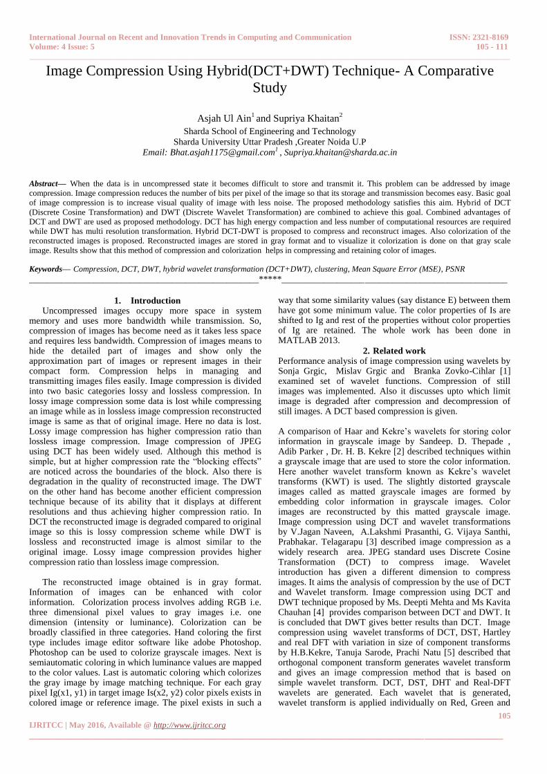
3. Methodology The Hybrid transform (combination of DCT and DWT) works on the advantages of both DCT and DWT in such a way that size of the image gets reduced to a large extent with higher compression ratio. Three-level decomposition is applied on the image by DWT and we get approximation images that are of size 8x8 and the remaining detailed coefficient images are made equal to zeroes. On the approximation image 2D DCT is applied. Then quantization is done and then run length coding is applied. The compressed image that is obtained will be in the form of gray image and to visualize that image it will be converted into colored image by process of colorization, hence saving the image storage capacity. This will help to compress the image as well as colorize that compressed images. This will help to visualize the additional information present in the gray image. Step 1: The first step involved in hybrid image compression is wavelet transform. Multi-resolution image analysis is performed by wavelet transform. In multi-resolution, image is simultaneously represented on different resolution levels. In 2-D images are considered as matrices of N rows and M columns while in wavelet transform image is decomposed in two parts; approximation part of an image which is low frequency part and another is detailed part of an image which is higher frequency part. Four sub-images are obtained at each level of the decomposition of the image: approximation image (LL), vertical detailed image (LH), horizontal detailed image (HL) and diagonal detailed image (HH). Then all the image coefficients are dropped except approximation image (LL) which is sent for second level decomposition
Figure 1: Three Level Decomposition of the wavelet. Step 2: The second step includes application of 2D DCT on approximation image. Approximation image is divided into 8x8 blocks. Image compression using DCT process includes:
1. The image is broken into 8x8 blocks of pixels. 2. Working from left to right, top to bottom, the DCT is
applied to each block. 3. Each block is compressed through quantization. 4. The array of compressed blocks that constitute the
image is stored in a drastically reduced amount of space.
5. The image is reconstructed through decompression, a process that uses the Inverse Discrete Cosine Transform (IDCT).
Step 2.1 DCT on an 8X8 block
Read the original image and get the values of the pixels from
the image in the blocks. Since DCT is designed to work on
pixel values ranging from -127 to 128 the original block is
levelled off by subtracting 128 from each entry. The discrete
cosine transform is accomplished by
D = TMT‟
Where T is the DCT matrix and M is the original image matrix
which is leveled off by subtracting 128.
Step 2.2 Quantization[17]
Our 8x8 block of DCT coefficients is now ready for
compression. This enables the user to decide on quality levels
ranging from 1 to 100, where 1 gives the poorest image quality
and highest compression, while 100 gives the best quality and
lower rate of compression. As a result, the compression ratio
can be tailored to suit different needs. DCT has predefined
quantization matrix and is used to quantize the 8x8 blocks.
International Journal on Recent and Innovation Trends in Computing and Communication ISSN: 2321-8169
Volume: 4 Issue: 5 105 - 111
____________________________________________________________________________________________________________________
107
IJRITCC | May 2016, Available @ http://www.ijritcc.org
_______________________________________________________________________________________________________
For a quality level greater than 50 (less compression, higher
image quality), the standard quantization matrix is multiplied
by (100-quality level)/50. For a quality level less than 50
(more compression, lower image quality), the standard
quantization matrix is multiplied by 50/quality level. The
scaled quantization matrix is then rounded and clipped to have
positive integer values ranging from 1 to 255.Quantization is
achieved by dividing each element in the transformed image
matrix D by corresponding element in the quantization matrix,
and then rounding to the nearest integer value.
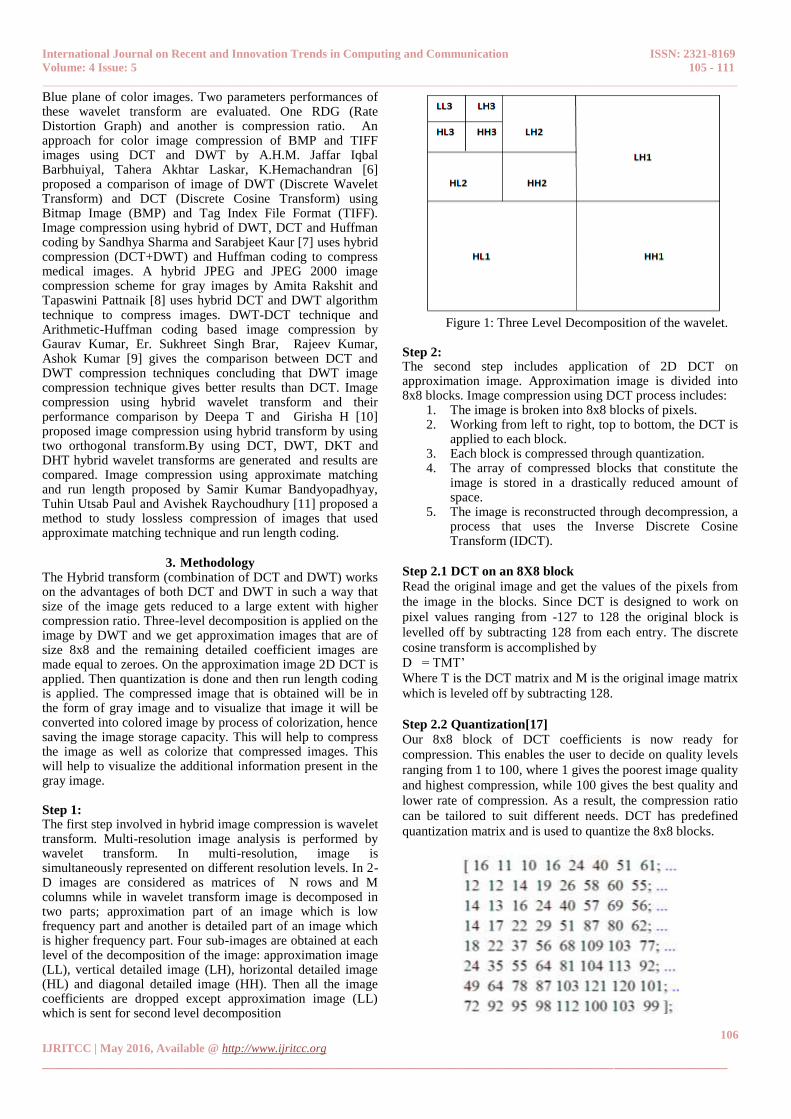
Step 2.3 Coding
Before storage, all coefficients of C are converted by an
encoder to a stream of binary data (01101011...). Run-length
encoding technique is used to encode the data. Run-length
encoding is a data compression algorithm that helps us encode
large runs of repeating items by only sending one item from
the run and a counter showing how many times this item is
repeated .
Figure 2: Compression of image
Step 3:
The image is then reconstructed through decompression.
Decompression process uses the Inverse Discrete Cosine
Transform (IDCT) and Inverse Discrete Wavelet Transform
(IDWT).
Figure 3: Decompression of the image
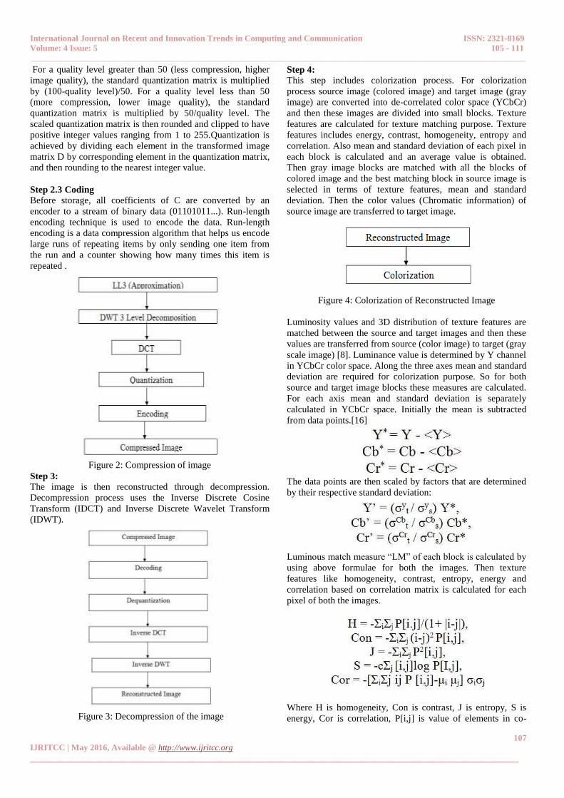
Step 4:
This step includes colorization process. For colorization
process source image (colored image) and target image (gray
image) are converted into de-correlated color space (YCbCr)
and then these images are divided into small blocks. Texture
features are calculated for texture matching purpose. Texture
features includes energy, contrast, homogeneity, entropy and
correlation. Also mean and standard deviation of each pixel in
each block is calculated and an average value is obtained.
Then gray image blocks are matched with all the blocks of
colored image and the best matching block in source image is
selected in terms of texture features, mean and standard
deviation. Then the color values (Chromatic information) of
source image are transferred to target image.
Figure 4: Colorization of Reconstructed Image
Luminosity values and 3D distribution of texture features are
matched between the source and target images and then these
values are transferred from source (color image) to target (gray
scale image) [8]. Luminance value is determined by Y channel
in YCbCr color space. Along the three axes mean and standard
deviation are required for colorization purpose. So for both
source and target image blocks these measures are calculated.
For each axis mean and standard deviation is separately
calculated in YCbCr space. Initially the mean is subtracted
from data points.[16]
The data points are then scaled by factors that are determined
by their respective standard deviation:
Luminous match measure “LM” of each block is calculated by
using above formulae for both the images. Then texture
features like homogeneity, contrast, entropy, energy and
correlation based on correlation matrix is calculated for each
pixel of both the images.
Where H is homogeneity, Con is contrast, J is entropy, S is
energy, Cor is correlation, P[i,j] is value of elements in co-
International Journal on Recent and Innovation Trends in Computing and Communication ISSN: 2321-8169
Volume: 4 Issue: 5 105 - 111
____________________________________________________________________________________________________________________
108
IJRITCC | May 2016, Available @ http://www.ijritcc.org
_______________________________________________________________________________________________________
occurrence matrix and i,j are the coordinates, μi μj are mean of
pi and pj respectively.
Now these texture features are weighed appropriately, weights
are calculated for each of these features based on formula
Where ω is the parameter under consideration
„TM‟ that is texture based measure is calculated for each
block in both the source and target images. ‟TM‟ is based on
Euclidean distance. After this „E‟ that is a similarity measure
for both the windows is calculated. „E‟ gives equal weight to
TM and LM. Based on this similarity measure „E‟ each block
in target image (gray scale) is compared with each block in
source image (Color) and the best matching block is selected.
After this the chromatic (Color) values of pixels in source
image are transferred to the pixels in target image giving
colorization to gray image. But luminosity properties of the
pixels are retained.
Performance parameters
a. Mean Square Error (MSE)
Mean Square Error (or Mean Square Deviation) which gives
the average of the deviations (or average of the errors) is
mathematically represented as
b. Peak Signal to Noise Ratio (PSNR):
It is that quality factor which gives the measure of the peak
error that is the ratio between the maximum possible power of
a signal and power of the corrupting noise. PSNR gives the
quality measure between the original and reconstructed image.
It is calculated as follows
IV. Experimental Results
To do the compression process along with the colouration, a
MATLAB code is devised and is run on certain images. The
test results are viewed as follows.
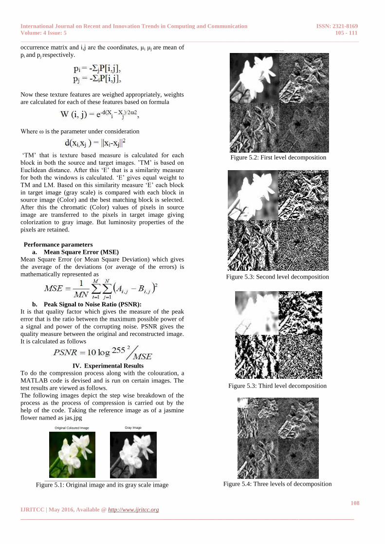
The following images depict the step wise breakdown of the
process as the process of compression is carried out by the
help of the code. Taking the reference image as of a jasmine
flower named as jas.jpg
Original Coloured Image Gray Image
Figure 5.1: Original image and its gray scale image
first level
Figure 5.2: First level decomposition
Second level
Figure 5.3: Second level decomposition
Third level
Figure 5.3: Third level decomposition
Three level decomposition
Figure 5.4: Three levels of decomposition

International Journal on Recent and Innovation Trends in Computing and Communication ISSN: 2321-8169
Volume: 4 Issue: 5 105 - 111
____________________________________________________________________________________________________________________
109
IJRITCC | May 2016, Available @ http://www.ijritcc.org
_______________________________________________________________________________________________________
Third level Image
Compressed DCT Image
Reconstructed Image after Compression
Figure 5.5: Image after compression
Gray Image Compressed Image
Figure 5.6: Gray image and compressed image
Here we take a pre-determined colored picture(set as source
image for the coloration), use the same as reference for the
coloration process of the grey image that is obtained from the
within the process.
Source Colour Image Compressed Hybrid Image
Figure 5.7: Source colour image and compressed hybrid image
source image clusters target image clusters
Figure 5.8: Source and Target image clusters
Figure 5.9: Original image and reconstructed
Colorized image
Figure 5: Image compression carried out in MATLAB using
the proposed Hybrid Technique
As is shown in the above figures the coloration process is quite
well dependent on the choice of the colour tone in the source
image. The quality of the final image may be more and more
efficient if the source image for coloration is similar to that of
the original image in terms of its color. Hence we may set the
colour of the final image as we like depending upon the
source.
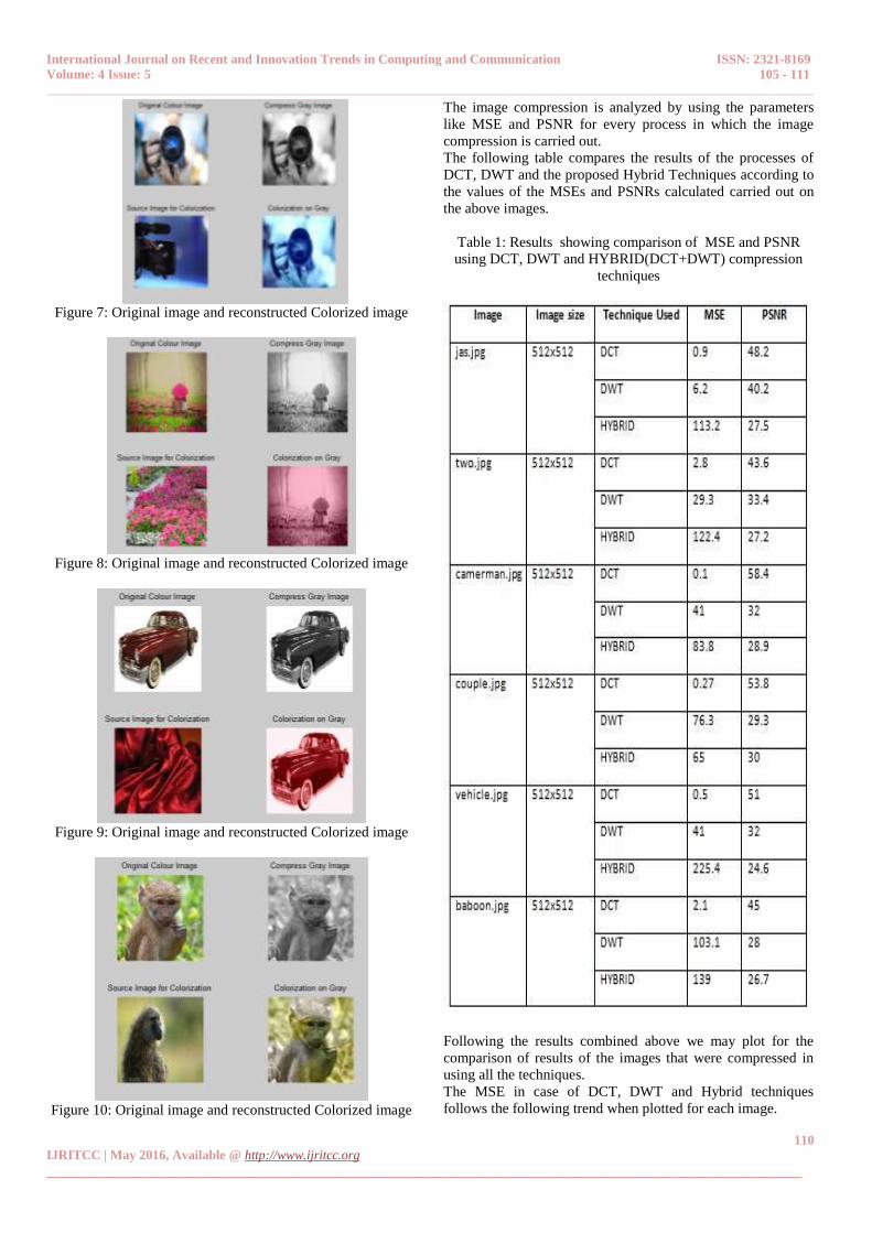
The following images depict the final stage images of the rest
of the images that were color compressed using the proposed
technique, Hybrid Technique (DCT+ DWT).
Figure 6: Original image and reconstructed Colorized image
International Journal on Recent and Innovation Trends in Computing and Communication ISSN: 2321-8169
Volume: 4 Issue: 5 105 - 111
____________________________________________________________________________________________________________________
110
IJRITCC | May 2016, Available @ http://www.ijritcc.org
_______________________________________________________________________________________________________
Figure 7: Original image and reconstructed Colorized image
Figure 8: Original image and reconstructed Colorized image
Figure 9: Original image and reconstructed Colorized image
Figure 10: Original image and reconstructed Colorized image
The image compression is analyzed by using the parameters
like MSE and PSNR for every process in which the image
compression is carried out.
The following table compares the results of the processes of
DCT, DWT and the proposed Hybrid Techniques according to
the values of the MSEs and PSNRs calculated carried out on
the above images.
Table 1: Results showing comparison of MSE and PSNR
using DCT, DWT and HYBRID(DCT+DWT) compression
techniques
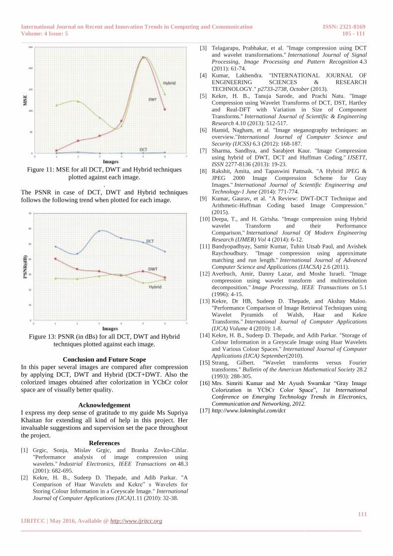
Following the results combined above we may plot for the
comparison of results of the images that were compressed in
using all the techniques.
The MSE in case of DCT, DWT and Hybrid techniques
follows the following trend when plotted for each image.
International Journal on Recent and Innovation Trends in Computing and Communication ISSN: 2321-8169
Volume: 4 Issue: 5 105 - 111
____________________________________________________________________________________________________________________
111
IJRITCC | May 2016, Available @ http://www.ijritcc.org
_______________________________________________________________________________________________________
Figure 11: MSE for all DCT, DWT and Hybrid techniques
plotted against each image.
.
The PSNR in case of DCT, DWT and Hybrid techniques
follows the following trend when plotted for each image.
Figure 13: PSNR (in dBs) for all DCT, DWT and Hybrid
techniques plotted against each image.
Conclusion and Future Scope
In this paper several images are compared after compression
by applying DCT, DWT and Hybrid (DCT+DWT. Also the
colorized images obtained after colorization in YCbCr color
space are of visually better quality.
Acknowledgement
I express my deep sense of gratitude to my guide Ms Supriya
Khaitan for extending all kind of help in this project. Her
invaluable suggestions and supervision set the pace throughout
the project.
References [1] Grgic, Sonja, Mislav Grgic, and Branka Zovko-Cihlar.
"Performance analysis of image compression using
wavelets." Industrial Electronics, IEEE Transactions on 48.3
(2001): 682-695.
[2] Kekre, H. B., Sudeep D. Thepade, and Adib Parkar. "A
Comparison of Haar Wavelets and Kekre‟ s Wavelets for
Storing Colour Information in a Greyscale Image." International
Journal of Computer Applications (IJCA)1.11 (2010): 32-38.
[3] Telagarapu, Prabhakar, et al. "Image compression using DCT
and wavelet transformations." International Journal of Signal
Processing, Image Processing and Pattern Recognition 4.3
(2011): 61-74.
[4] Kumar, Lakhendra. "INTERNATIONAL JOURNAL OF
ENGINEERING SCIENCES & RESEARCH
TECHNOLOGY." p2733-2738, October (2013).
[5] Kekre, H. B., Tanuja Sarode, and Prachi Natu. "Image
Compression using Wavelet Transforms of DCT, DST, Hartley
and Real-DFT with Variation in Size of Component
Transforms." International Journal of Scientific & Engineering
Research 4.10 (2013): 512-517.
[6] Hamid, Nagham, et al. "Image steganography techniques: an
overview."International Journal of Computer Science and
Security (IJCSS) 6.3 (2012): 168-187.
[7] Sharma, Sandhya, and Sarabjeet Kaur. "Image Compression
using hybrid of DWT, DCT and Huffman Coding." IJSETT,
ISSN 2277-8136 (2013): 19-23.
[8] Rakshit, Amita, and Tapaswini Pattnaik. "A Hybrid JPEG &
JPEG 2000 Image Compression Scheme for Gray
Images." International Journal of Scientific Engineering and
Technology-1 June (2014): 771-774.
[9] Kumar, Gaurav, et al. "A Review: DWT-DCT Technique and
Arithmetic-Huffman Coding based Image Compression."
(2015).
[10] Deepa, T., and H. Girisha. "Image compression using Hybrid
wavelet Transform and their Performance
Comparison." International Journal Of Modern Engineering
Research (IJMER) Vol 4 (2014): 6-12.
[11] Bandyopadhyay, Samir Kumar, Tuhin Utsab Paul, and Avishek
Raychoudhury. "Image compression using approximate
matching and run length." International Journal of Advanced
Computer Science and Applications (IJACSA) 2.6 (2011).
[12] Averbuch, Amir, Danny Lazar, and Moshe Israeli. "Image
compression using wavelet transform and multiresolution
decomposition." Image Processing, IEEE Transactions on 5.1
(1996): 4-15.
[13] Kekre, Dr HB, Sudeep D. Thepade, and Akshay Maloo.
"Performance Comparison of Image Retrieval Techniques using
Wavelet Pyramids of Walsh, Haar and Kekre
Transforms." International Journal of Computer Applications
(IJCA) Volume 4 (2010): 1-8.
[14] Kekre, H. B., Sudeep D. Thepade, and Adib Parkar. "Storage of
Colour Information in a Greyscale Image using Haar Wavelets
and Various Colour Spaces." International Journal of Computer
Applications (IJCA) September(2010).
[15] Strang, Gilbert. "Wavelet transforms versus Fourier
transforms." Bulletin of the American Mathematical Society 28.2
(1993): 288-305.
[16] Mrs. Simriti Kumar and Mr Ayush Swarnkar “Gray Image
Colorization in YCbCr Color Space”, 1st International
Conference on Emerging Technology Trends in Electronics,
Communication and Networking, 2012.
[17] http://www.lokminglui.com/dct


![Audio Signal Compression using DCT and LPC … to DCT. PSNR and MSE are almost same for both the techniques. REFERENCES [1] Audio and Speech Compression Using DCT and DWT Techniques](https://img.pdfslide.net/doc/110x75/5aa23b2a7f8b9ab4208cc445/audio-signal-compression-using-dct-and-lpc-to-dct-psnr-and-mse-are-almost-same.jpg)
![A Comparative study of Digital Watermarking algorithms DWT ... · (DCT), Discrete Wavelet Transform (DWT) and Singular Value Decomposition (SVD)[2]. The rest of the paper is organized](https://img.pdfslide.net/doc/110x75/5faec4be5f2aff6d172d895a/a-comparative-study-of-digital-watermarking-algorithms-dwt-dct-discrete-wavelet.jpg)