Embed Size (px)
DESCRIPTION
For fiber reinforced parts the consideration of anisotropic material behavior is required to receive reliable results. In the scope of this fact a procedure is described how to consider these effects in terms of process-structure interaction and how to achieve possible benefits such as weight reduction and shorter development cycles shown for examples of the industry . The developed procedures show how to consider the anisotropic mechanical behavior of injection molded short-fiber-reinforced plastics parts in FE analysis. It is shown how the existing information, which is provided by injection molding simulation software, can be processed and transferred into mechanical simulation models. The procedure is outlined with practical applications.
Citation preview

Improved Quality Prediction of Injection Molded Fiber Reinforced
Components by Considering Fiber Orientations
Sascha Pazour
Wolfgang Korte
PART Engineering GmbH
0049 2204 30677 26
© PART Engineering GmbH, www.part-gmbh.de

Plastics
CAE Services & Software
Technical Simulation Contract Simulation Services
in FEA
CAE Staffing Resident Engineers at
customers‘ sites
CAE Software - Process-Structure-Interaction
- Strength & Fatigue Assessment
Metals
S-Life
Elastomers

Material:
PA6+GF30
perpendicular
parallel
Influence of Fiber Orientation onto Material Properties
Fig. 2

Fiber Orientations in Short-Fiber-Reinforced Plastics
S1 Shear layer: Fibers oriented parallel to flow direction
S2 Mid layer: Fibers oriented perpendicular to flow direction
Fig. 3
Flow Direction X
X
Cut View X
Flow Direction
S1
S2
S1
Example
Micrograph
Pictures:
Thick
Mid Layer Thin
Mid Layer

Isotropic and Orthotropic Material Models
Isotropic Material Model
Orthotropic Material Model
Fig. 4
needs 2 material properties: Tensile Modulus E and Poisson ratio
needs 9 material properties:
Tensile modulii the 3 orthotropic axes E1, E2, E3
Shear modulii the 3 orthotropic planes G12, G13, G23
Poisson ratios 12, 13, 23
Further the position of the orthotropic axes (local element coordinate sytem)
with reference to the global coordinate system is needed

Degree of Orientation
Fig. 5
33
2322
131211
..
.
a
aa
aaa
000
000
001
33.000
033.00
0033.0
2
3 1
general case unidirectional quasi-isotropic
-90° +90° -45° +45° 0° -90° +90° -45° +45° 0° -90° +90° -45° +45° 0°
Schmelzeflussrichtung
Schmelzeflussrichtung
2
1

Example: Weld Lines
Isotropic Approach Fig. 6
Common Approach:
Isotropic
Schmelzeflussrichtung
Schmelzeflussrichtung

Example: Weld Lines
Anisotropic Approach Fig. 7
CONVERSE Approach:
Anisotropic
Schmelzeflussrichtung
Schmelzeflussrichtung

Fig. 8
Orientation and Degree of Orientation
from Injection Molding Simulation
shear layer
mid layer
[Part: Mann & Hummel]
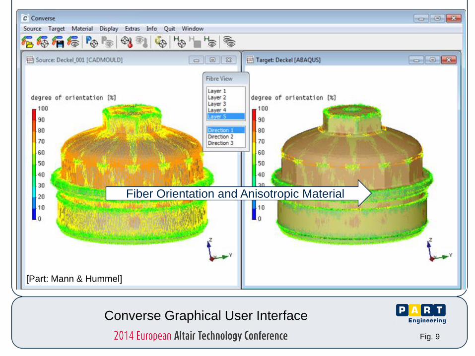
Fiber Orientation and Anisotropic Material
Fig. 9
Converse Graphical User Interface
[Part: Mann & Hummel]

Mesh Topology
Fig. 10
Converse IM solver mechanical solver
shell (mid-plane/surface) => shell (tria, quad)
shell (mid-plane/surface) => solid (tet, hex)
solid => solid (tet, hex)
unequal meshes
possible

Material Dialog
Fig.11

Mechanical Solver Injection Moulding Solver
- Moldflow
- Cadmould
- Sigma
- Moldex
- Fluent
- Simpoe
- 3D Timon
- Ansys
- Abaqus
- Optistruct
- Nastran
- Marc
- Samcef
- FEMFat
- Ncode
- Virtual.Lab
Orientations
Pressures
Temperatures
Wall Thicknesses
Residual Stresses
Shrinkage & Warpage
Weld Lines
Fig. 12
Converse Features and Interfaces

0
200
400
600
800
1000
1200
1400
0 1 2 3 4 5 6
Kra
ft [N
]
Verschiebung [mm]
Messung 1
Messung 2
isotrop
orthotrop
Example: Rotary Valve
Material: Grivory HTV 3H1
forc
e [N
]
displacement [mm]
test 1
test 2
FEA isotropic
FEA anisotropic
Fig. 13
[Part: Mann & Hummel]

Example: Air Intake Manifold
Material: Ultramid A3WG6
Fig. 14
[Part: Mann & Hummel]

Eigenfrequencies and Eigenmodes
0
100
200
300
400
500
600
700
800
900
1000
250,00 270,00 290,00 310,00 330,00 350,00 370,00 390,00
eff
ektive M
asse
[g]
Frequenz [Hz]
x-Richtung - isotrop y-Richtung - isotrop z-Richtung - isotrop
x-Richtung - orthotrop y-Richtung - orthotrop z-Richtung - orthotrop
x-direction-isotropic
x-direction-anisotropic
y-direction-isotropic
y-direction-anisotropic
z-direction-isotropic
z-direction-anisotropic
frequency [Hz]
effe
ctive
ma
ss [kg
]
Fig. 15
[Part: Mann & Hummel]

Example: Burst Pressure
Material: PP + GF20
Fig. 16

Cyclic Utilization Ratio for N=80000
A cycl,max (N) = 91%
Fatigue strength
assessment satisfied!
A cycl(N)
X(N)=63 MPa
Y(N)=42 MPa
S(S)=24 MPa
Fig.17
[Part: Mann & Hummel]

Failure Assessment
Fig. 18
[Part: Mann & Hummel]

Lens Bracket Example
Fig. 19
Part Geometry Fiber Orientation in Converse
[Valeo Lighting Systems]

Lens Bracket Example
Fig. 20
Frequency correlation – simulation to Xp. modal analysis
+5Hz
+30Hz
Converse
Isotropic
Average error – 4 Modes
Mode Experimental (Hz) Isotropic (Hz) Converse (Hz)
1 44 76 60
2 56 77 62
3 91 114 94
4 224 270 218 [Valeo Lighting Systems]
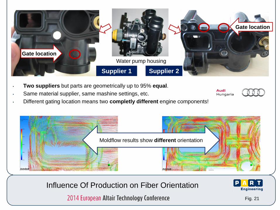
Influence Of Production on Fiber Orientation
Fig. 21
Supplier 2 Supplier 1
• Two suppliers but parts are geometrically up to 95% equal.
• Same material supplier, same mashine settings, etc.
• Different gating location means two completly different engine components!
Water pump housing
Gate location
Gate location
Moldflow results show different orientation

Influence Of Production on Anisotropic Part Stiffness
Fig. 22
Blue – Supplier 1
Red – Supplier 2
Dotted – Isotropic material
fiber orientation and material model by
4. isotropic vs. anisotropic results
∆ - 62%
Untolerable error if homogeneous
isotropic material is used!
3. displacements
1. distributed pressure on sealing contact surface
2. results evaluated on a path
Dis
pla
cem
ent
True distance along path

Fig. 23
www.part-gmbh.de What´s New?
Converse Installation

consider the real part properties
get better predictions of
strength & deformation
by using data already
available
integrates smoothly into
your day-to-day CAE routines
straigthforward easy-to-use
Fig. 24
Add Value to Your Mechanical Simulation

Fig. 25
Thank you for your Attention!
Questions?