Embed Size (px)
Citation preview
1
Software Engineering
By
Mobeen Mustafa
2
Course outline
• Unit 1: Software Engineering Basics Unit 2: Process Models and Software Life Cycles• Unit 3: Software Requirements • Unit 4: Unified Modeling Language (UML)• Unit 5: Design Basics and Software Architecture• Unit 6: OO Analysis and Design • Unit 7: Design Patterns• Unit 8: Testing and Reliability • Unit 9: Software Engineering Management and Economics

3
Reference
• These slides are based on:– Lecture slides by Ian Summerville, see
http://www.comp.lancs.ac.uk/computing/resources/ser/
4
Overview
• Build-and-fix model• Waterfall model• Rapid prototyping model• Incremental model• Evolutionary• Synchronize-and-stabilize model• Spiral model
5
Software Life-Cycle Models
• Life-cycle model (also, process model)• The software development and operation
activities and their ordering– Requirements elicitation– Specification– Design– Implementation– Integration– Maintenance phase– Retirement– …
6
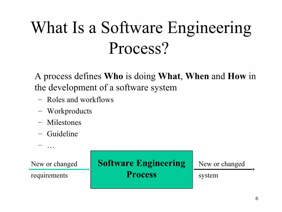
New or changed
requirements
New or changed
system
Software EngineeringProcess
What Is a Software Engineering Process?
A process defines Who is doing What, When and How in the development of a software system– Roles and workflows
– Workproducts
– Milestones
– Guideline
– …
7
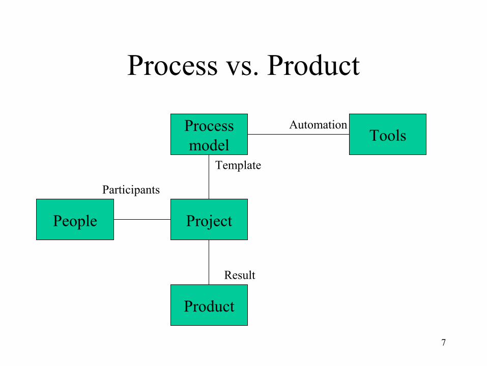
Process vs. Product
Processmodel
Project
Product
People
Tools
Template
Participants
Result
Automation
8
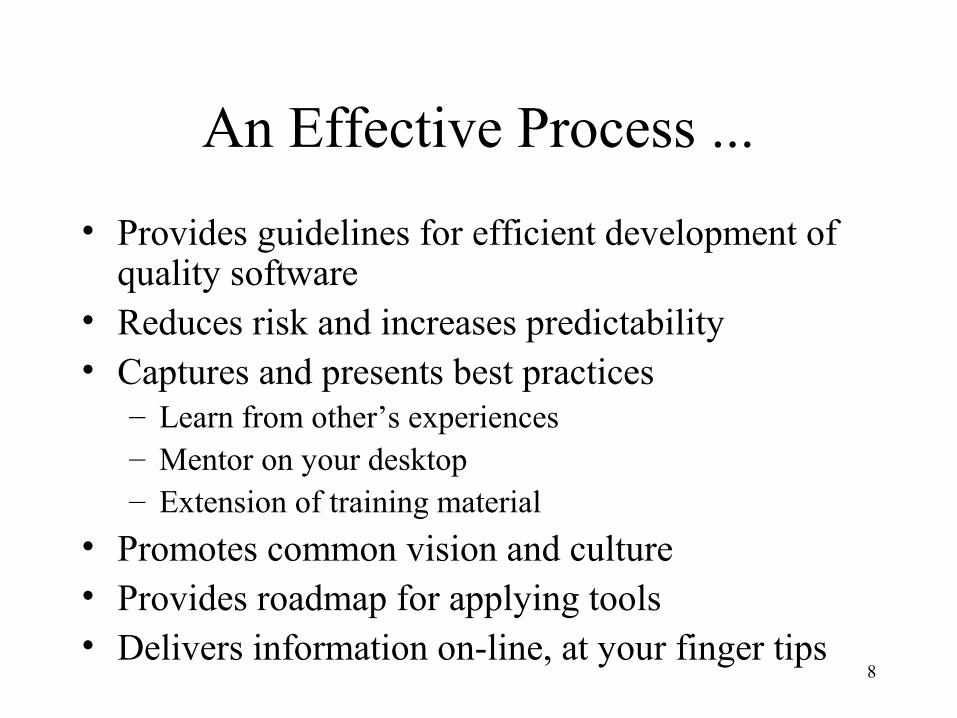
An Effective Process ...
• Provides guidelines for efficient development of quality software
• Reduces risk and increases predictability • Captures and presents best practices
– Learn from other’s experiences– Mentor on your desktop– Extension of training material
• Promotes common vision and culture• Provides roadmap for applying tools• Delivers information on-line, at your finger tips
9
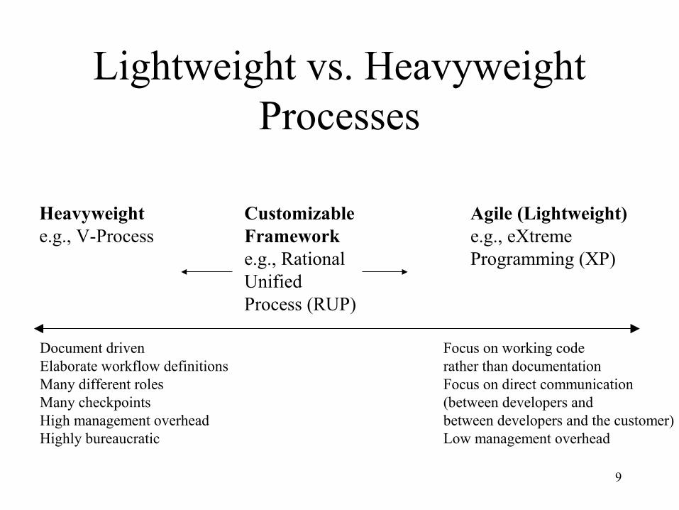
Lightweight vs. Heavyweight Processes
Document drivenElaborate workflow definitionsMany different rolesMany checkpointsHigh management overheadHighly bureaucratic
Focus on working coderather than documentationFocus on direct communication(between developers andbetween developers and the customer)Low management overhead
Heavyweighte.g., V-Process
CustomizableFrameworke.g., RationalUnifiedProcess (RUP)
Agile (Lightweight)e.g., eXtremeProgramming (XP)
10
• Process used should depend on type of product which is being developed– For large systems, management is usually the
principal problem so you need a strictly managed process. For smaller systems, more informality is possible.
• High costs may be incurred if you force an inappropriate process on a development team
Process choice
©Ian Sommerville 1995 [modified]
11
Build and Fix Model
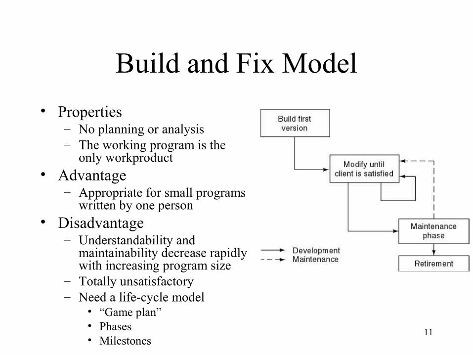
• Properties– No planning or analysis– The working program is the
only workproduct• Advantage
– Appropriate for small programs written by one person
• Disadvantage– Understandability and
maintainability decrease rapidly with increasing program size
– Totally unsatisfactory– Need a life-cycle model
• “Game plan” • Phases• Milestones
12
Waterfall Model
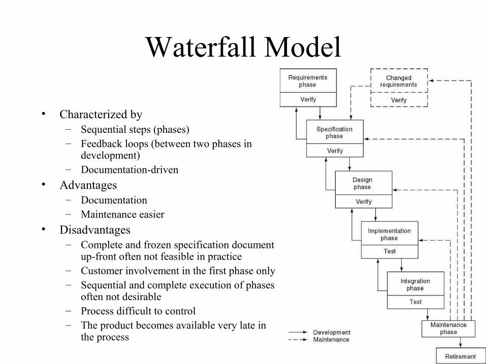
• Characterized by– Sequential steps (phases)– Feedback loops (between two phases in
development)– Documentation-driven
• Advantages – Documentation– Maintenance easier
• Disadvantages– Complete and frozen specification document
up-front often not feasible in practice– Customer involvement in the first phase only– Sequential and complete execution of phases
often not desirable– Process difficult to control– The product becomes available very late in
the process
13
Rapid Prototyping Model
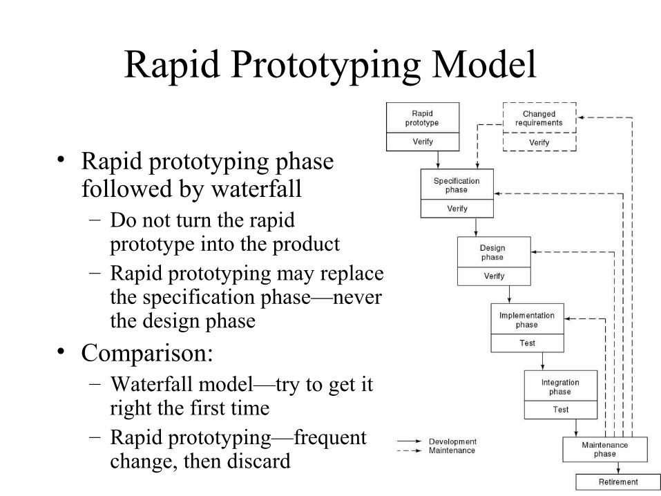
• Rapid prototyping phase followed by waterfall– Do not turn the rapid
prototype into the product– Rapid prototyping may replace
the specification phase—never the design phase
• Comparison:– Waterfall model—try to get it
right the first time– Rapid prototyping—frequent
change, then discard
14
Advantages and Disadvantages
• Advantages– Requirements better specified and validated– Early feasibility analysis– Strong involvement of the customer in the
prototyping phase
• Disadvantage– Higher development effort– Danger that due to schedule slip, the prototype
becomes part of the product
15
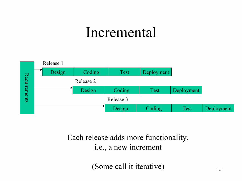
Incremental
Design Coding Test Deployment
Design Coding Test Deployment
Design Coding Test Deployment
Requirem
ents
Release 1
Release 2
Release 3
Each release adds more functionality, i.e., a new increment
(Some call it iterative)
16
Incremental Model (contd)
• Waterfall, rapid prototyping models– Operational quality complete product at end
• Incremental model– Operational quality portion of product within weeks
• Less traumatic• Smaller capital outlay, rapid return on investment
17
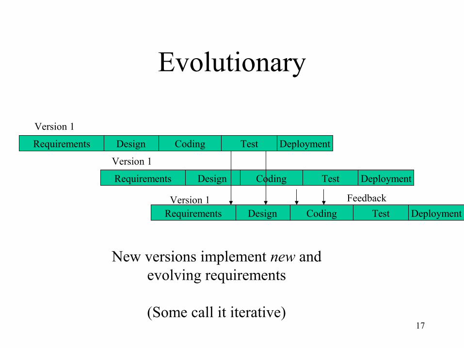
Evolutionary
Design Coding Test DeploymentRequirements
Design Coding Test DeploymentRequirements
Design Coding Test DeploymentRequirements
Feedback
Version 1
Version 1
Version 1
New versions implement new and evolving requirements
(Some call it iterative)
18
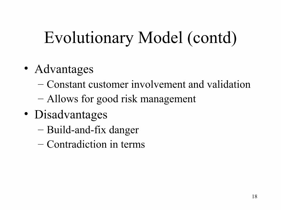
Evolutionary Model (contd)
• Advantages– Constant customer involvement and validation– Allows for good risk management
• Disadvantages– Build-and-fix danger– Contradiction in terms
19
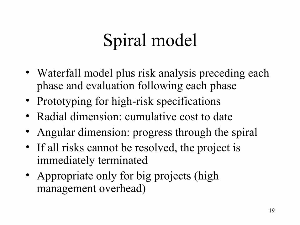
Spiral model
• Waterfall model plus risk analysis preceding each phase and evaluation following each phase
• Prototyping for high-risk specifications• Radial dimension: cumulative cost to date• Angular dimension: progress through the spiral• If all risks cannot be resolved, the project is
immediately terminated• Appropriate only for big projects (high
management overhead)
20
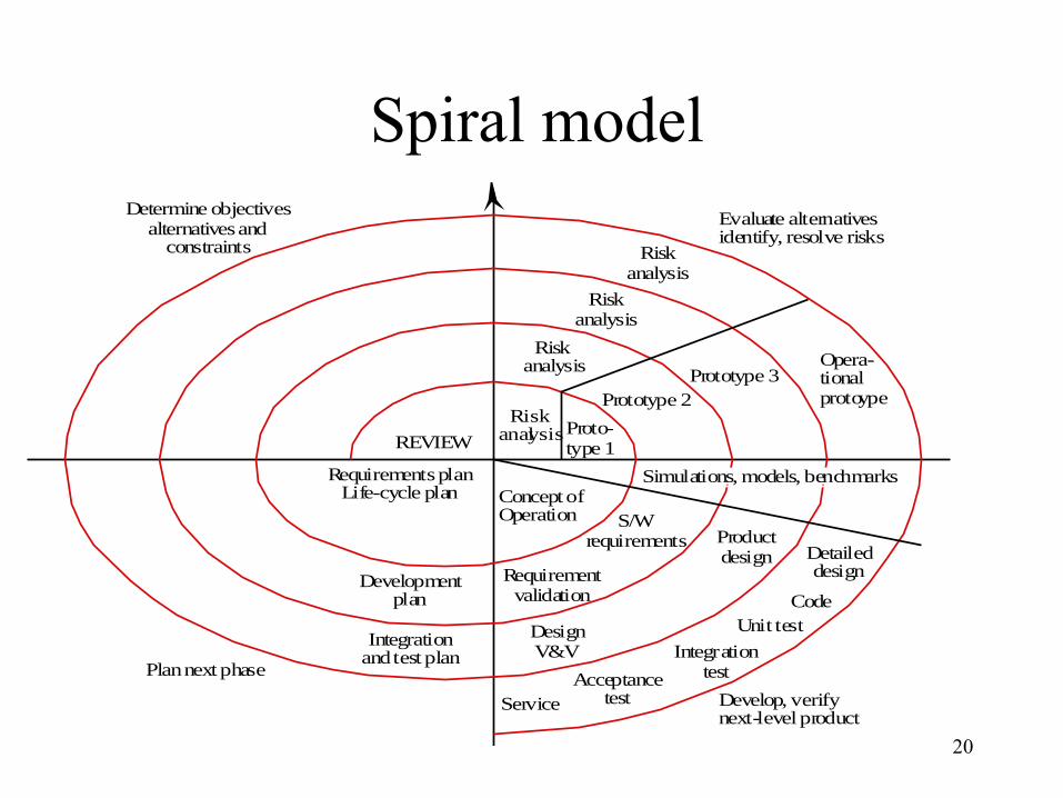
Spiral model
Riskanalysis
Riskanalysis
Riskanalysis
RiskanalysisProto-
type 1
Prototype 2Prototype 3
Opera-tionalprotoype
Concept ofOperation
Simulations, models, benchmarks
S/Wrequirements
Requirementvalidation
DesignV&V
Productdesign Detailed
design
CodeUnit test
IntegrationtestAcceptance
testService Develop, verifynext-level product
Evaluate alternativesidentify, resolve risks
Determine objectivesalternatives and
constraints
Plan next phase
Integrationand test plan
Developmentplan
Requirements planLife-cycle plan
REVIEW
21
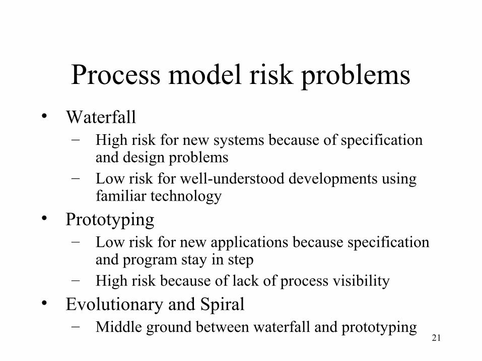
Process model risk problems• Waterfall
– High risk for new systems because of specification and design problems
– Low risk for well-understood developments using familiar technology
• Prototyping– Low risk for new applications because specification
and program stay in step– High risk because of lack of process visibility
• Evolutionary and Spiral– Middle ground between waterfall and prototyping
22
Hybrid process models• Large systems are usually made up of several
sub-systems• The same process model need not be used for
all subsystems• Prototyping for high-risk specifications• Waterfall model for well-understood
developments• Taylor the process to a problem
23
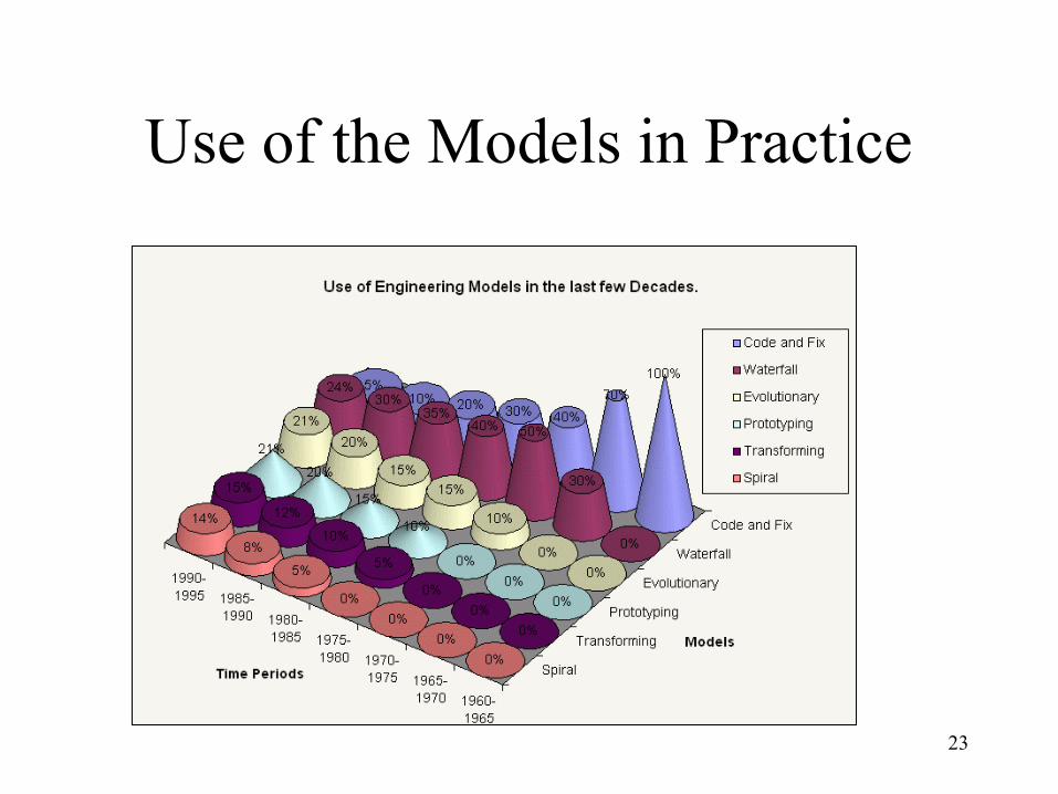
Use of the Models in Practice
24
• The fundamental problem with software– The software process is badly managed
• Understanding existing processes
• Introducing process changes to achieve organisational objectives which are usually focused on quality improvement, cost reduction and schedule acceleration
Process improvement
©Ian Sommerville 1995 [modified]
25
Reference
• These slides are based on:– Lecture slides by Ian Summerville, see
http://www.comp.lancs.ac.uk/computing/resources/ser/
26
Rational Unified Process – Main Characteristics
• Iterative and incremental• Use-case-driven• Architecture-centric• Uses UML as its modeling notation• Process framework
– Comprehensive set of document templates, process workflow templates, and process guidelines
– Distributed by IBM/Rational on a CD
27
Rational Unified Process Is Use-Case-Driven
• Use cases are concise, simple, and understandable by a wide range of stakeholders– End users, developers and acquirers understand functional
requirements of the system
• Use cases drive numerous activities in the process:– Creation and validation of the design model– Definition of test cases and procedures of the test model– Planning of iterations– Creation of user documentation– System deployment
• Use cases help synchronize the content of different models
28
Rational Unified Process Is Architecture-Centric
• Architecture is the focus of the elaboration phase– Building, validating, and baselining the architecture constitute the
primary objective of elaboration
• The Architectural Prototype validates the architecture and serves as the baseline for the rest of development
• The Software Architecture Description is the primary artifact that documents the architecture chosen
• Other artifacts derive from architecture:– Design guidelines including use of patterns and idioms– Product structure– Team structure
29
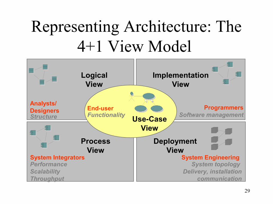
Representing Architecture: The 4+1 View Model
Process View
Deployment View
Logical View
Implementation View
Programmers Software management
PerformanceScalabilityThroughput
System IntegratorsSystem topology
Delivery, installationcommunication
System Engineering
Use-Case View
Structure
Analysts/Designers End-user
Functionality
30
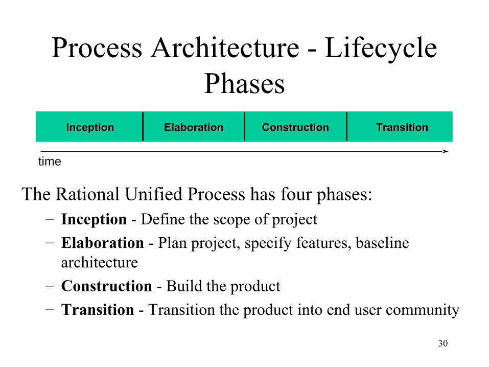
InceptionInception ElaborationElaboration ConstructionConstruction TransitionTransition
Process Architecture - Lifecycle Phases
The Rational Unified Process has four phases:– Inception - Define the scope of project
– Elaboration - Plan project, specify features, baseline architecture
– Construction - Build the product– Transition - Transition the product into end user community
time
31
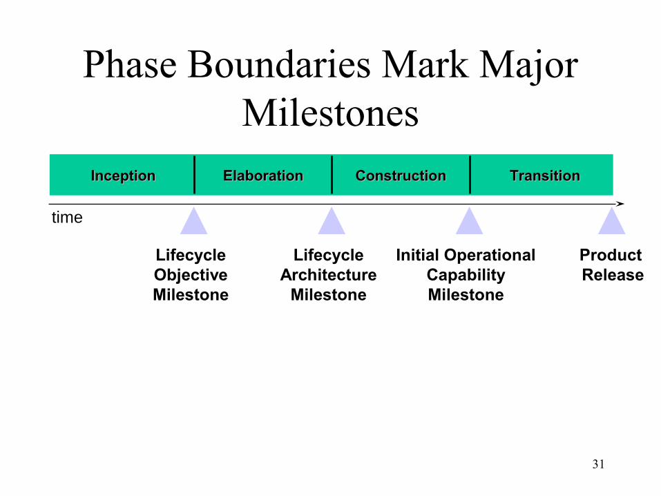
InceptionInception ElaborationElaboration ConstructionConstruction TransitionTransition
Phase Boundaries Mark Major Milestones
Lifecycle Objective Milestone
Lifecycle Architecture
Milestone
Initial Operational Capability Milestone
Product Release
time
32
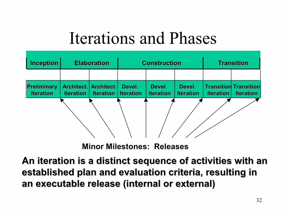
Iterations and Phases
An An iterationiteration is a distinct sequence of activities with an is a distinct sequence of activities with an established plan and evaluation criteria, resulting in established plan and evaluation criteria, resulting in an executable release (internal or external)an executable release (internal or external)
PreliminaryPreliminaryIterationIteration
Architect.Architect.IterationIteration
Architect.Architect.IterationIteration
Devel. Devel. IterationIteration
Devel. Devel. IterationIteration
Devel. Devel. IterationIteration
TransitionTransitionIterationIteration
TransitionTransitionIterationIteration
InceptionInception ElaborationElaboration ConstructionConstruction TransitionTransition
Minor Milestones: Releases
33
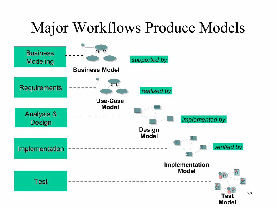
Major Workflows Produce Models
Analysis & Analysis & DesignDesign
DesignModel
ImplementationModel
TestModel
realized by
implemented by
verified by
RequirementsRequirements
ImplementationImplementation
TestTest
Use-CaseModel
BusinessBusinessModelingModeling
Business Model
supported by
34
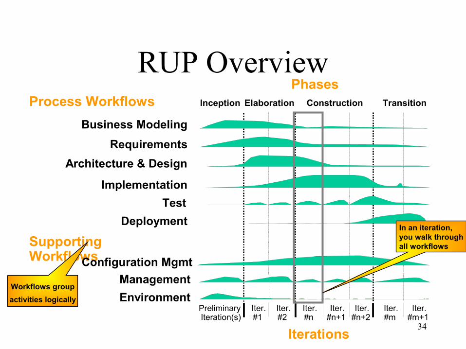
RUP Overview
Management
Environment
Business Modeling
Implementation
Test
Architecture & Design
Preliminary Iteration(s)
Iter.#1
PhasesProcess Workflows
Iterations
Supporting Workflows
Iter.#2
Iter.#n
Iter.#n+1
Iter.#n+2
Iter.#m
Iter.#m+1
Deployment
Configuration Mgmt
Requirements
Elaboration TransitionInception Construction
Workflows group
activities logically
In an iteration,you walk throughall workflows
35
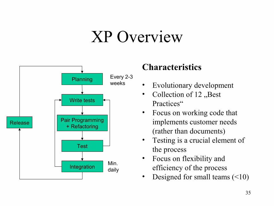
XP Overview
Characteristics
• Evolutionary development• Collection of 12 „Best
Practices“• Focus on working code that
implements customer needs (rather than documents)
• Testing is a crucial element of the process
• Focus on flexibility and efficiency of the process
• Designed for small teams (<10)
Write tests
Planning
Test
Pair Programming+ Refactoring
IntegrationMin.daily
Every 2-3weeks
Release
36
XP Practices (I)
• The planning game– Stakeholder meeting to plan the next iteration
– Business people decide on business value of features
– Developers on the technical risk of features and predicted effort per feature
• Small releases– Start with the smallest useful feature set; release early and often,
adding a few features each time
• Metaphor– Each project has an organizing metaphor, a providing easy to
remember naming conventions
37
XP Practices (II)
• Simple Design– Always use the simplest possible design that gets the job done
(runs the tests and states intentions of the programmer)
– No speculative genericity
• Testing– Test-first: write test, then implement it
– Programmers write unit tests and customers write acceptance tests
• Refactoring– Refactoring is done continuously; the code is always kept clean
38
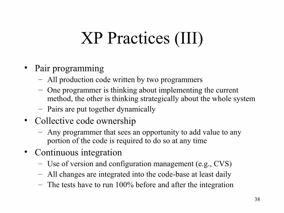
XP Practices (III)
• Pair programming– All production code written by two programmers– One programmer is thinking about implementing the current
method, the other is thinking strategically about the whole system– Pairs are put together dynamically
• Collective code ownership– Any programmer that sees an opportunity to add value to any
portion of the code is required to do so at any time
• Continuous integration– Use of version and configuration management (e.g., CVS)– All changes are integrated into the code-base at least daily– The tests have to run 100% before and after the integration
39
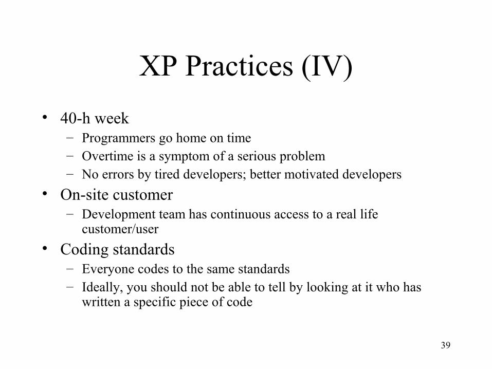
XP Practices (IV)
• 40-h week– Programmers go home on time– Overtime is a symptom of a serious problem– No errors by tired developers; better motivated developers
• On-site customer– Development team has continuous access to a real life
customer/user
• Coding standards– Everyone codes to the same standards– Ideally, you should not be able to tell by looking at it who has
written a specific piece of code
40
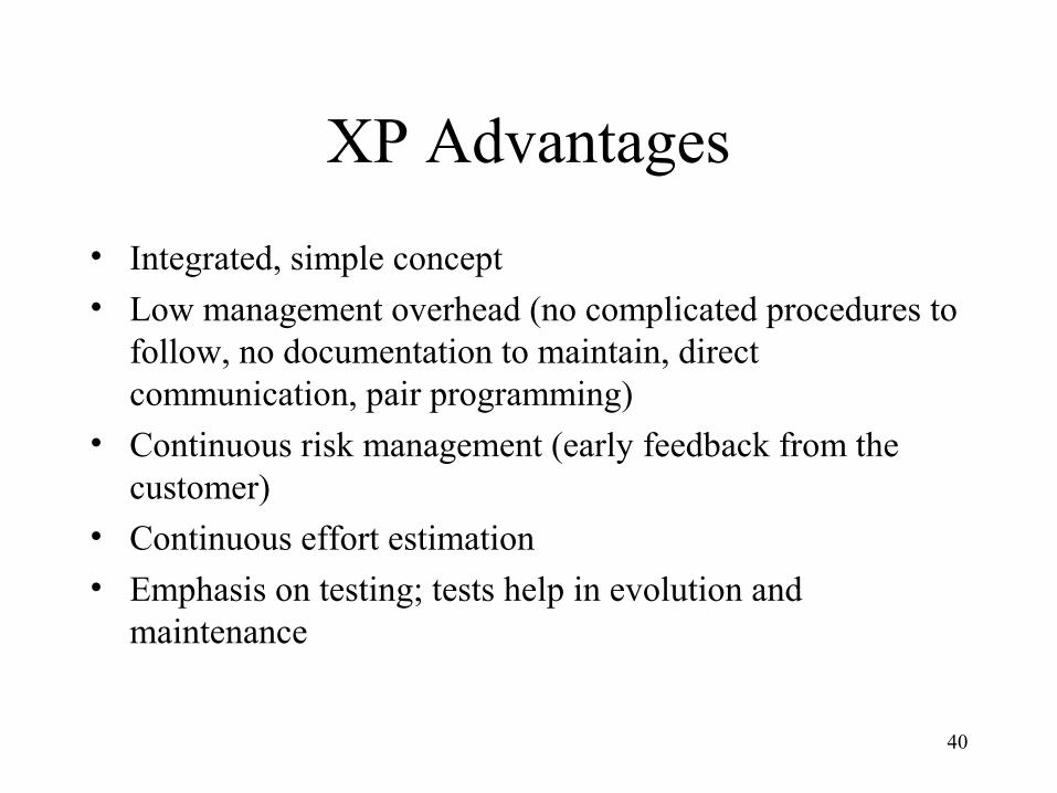
XP Advantages
• Integrated, simple concept• Low management overhead (no complicated procedures to
follow, no documentation to maintain, direct communication, pair programming)
• Continuous risk management (early feedback from the customer)
• Continuous effort estimation
• Emphasis on testing; tests help in evolution and maintenance
41
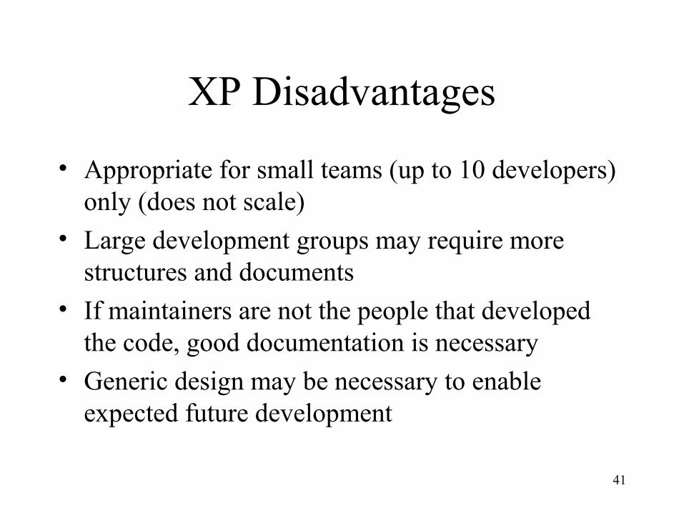
XP Disadvantages
• Appropriate for small teams (up to 10 developers) only (does not scale)
• Large development groups may require more structures and documents
• If maintainers are not the people that developed the code, good documentation is necessary
• Generic design may be necessary to enable expected future development
42
Reading
• RUP– Craig Larman, Applying UML and Patterns: An Introduction to Object-
Oriented Analysis and Design and the Unified Process, Prentice-Hall, 2002 (2nd edition)
– Kendall Scott. The Unified Process Explained. Addison Wesley, 2001• Agile development
– Kent Beck, Extreme Programming: Explained, Addison-Wesley, 1999– R. Jeffries, C. Hendrikson, A. Anderson, Extreme Programming Installed,
Addison-Wesley, 2001• http://member.netease.com/~wooce/tip/se/
– Alistair Cockburn, Agile Software Development, Addison-Wesley 2002
• Online-Ressourcen– http://www.xprogramming.com– http://www.xprogramming.org– http://groups.yahoo.com/group/extremeprogramming– http://c2.com
43
Process improvement stages
• Process analysis– Model and analyse (quantitatively if possible) existing
processes
• Improvement identification– Identify quality, cost or schedule bottlenecks
• Process change introduction– Modify the process to remove identified bottlenecks
• Process change training– Train staff involved in new process proposals
• Change tuning– Evolve and improve process improvements
©Ian Sommerville 1995
44
Software process improvement initiatives
• Capability maturity model (CMM)– http://www.sei.cmu.edu/cmm/cmms/cmms.html
• ISO 9000-series
• ISO/IEC 15504 – Standard for Software Process Assessment (SPICE)– http://www-sqi.cit.gu.edu.au/spice/
©Steven Schach 2002 [modified]
45
Capability Maturity Model
• A set of strategies for improving the software process– SW–CMM for software– P–CMM for human resources (“people”)– SE–CMM for systems engineering– IPD–CMM for integrated product development– SA–CMM for software acquisition
• These strategies are being unified into CMMI (capability maturity model integration)
• Developed by Software Engineering Institute (SEI)
©Steven Schach 2002 [modified]
46
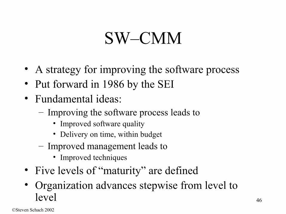
SW–CMM
• A strategy for improving the software process• Put forward in 1986 by the SEI • Fundamental ideas:
– Improving the software process leads to• Improved software quality• Delivery on time, within budget
– Improved management leads to• Improved techniques
• Five levels of “maturity” are defined• Organization advances stepwise from level to
level©Steven Schach 2002
47
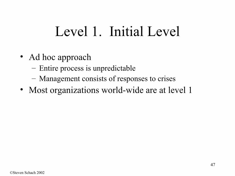
Level 1. Initial Level
• Ad hoc approach– Entire process is unpredictable– Management consists of responses to crises
• Most organizations world-wide are at level 1
©Steven Schach 2002
48
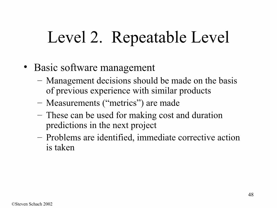
Level 2. Repeatable Level
• Basic software management– Management decisions should be made on the basis
of previous experience with similar products– Measurements (“metrics”) are made– These can be used for making cost and duration
predictions in the next project– Problems are identified, immediate corrective action
is taken
©Steven Schach 2002
49
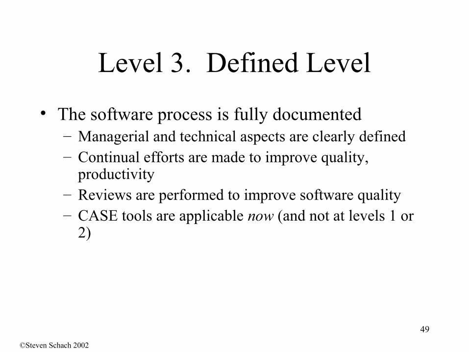
Level 3. Defined Level
• The software process is fully documented– Managerial and technical aspects are clearly defined– Continual efforts are made to improve quality,
productivity– Reviews are performed to improve software quality– CASE tools are applicable now (and not at levels 1 or
2)
©Steven Schach 2002
50
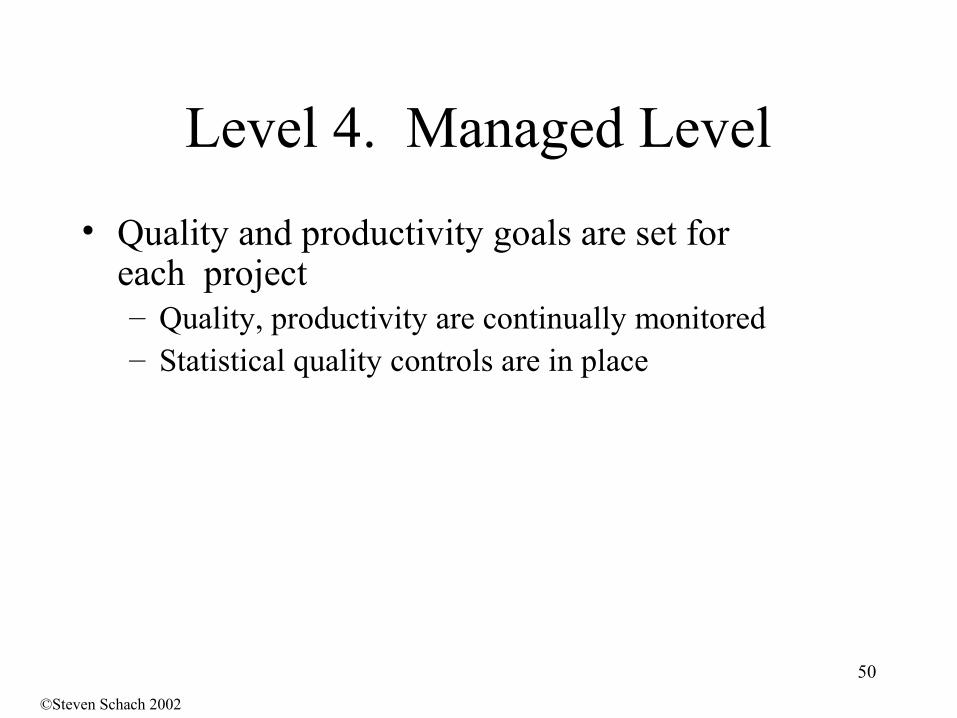
Level 4. Managed Level
• Quality and productivity goals are set for each project– Quality, productivity are continually monitored– Statistical quality controls are in place
©Steven Schach 2002
51
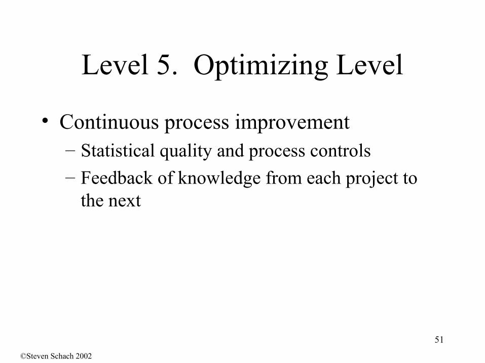
Level 5. Optimizing Level
• Continuous process improvement– Statistical quality and process controls– Feedback of knowledge from each project to
the next
©Steven Schach 2002
52
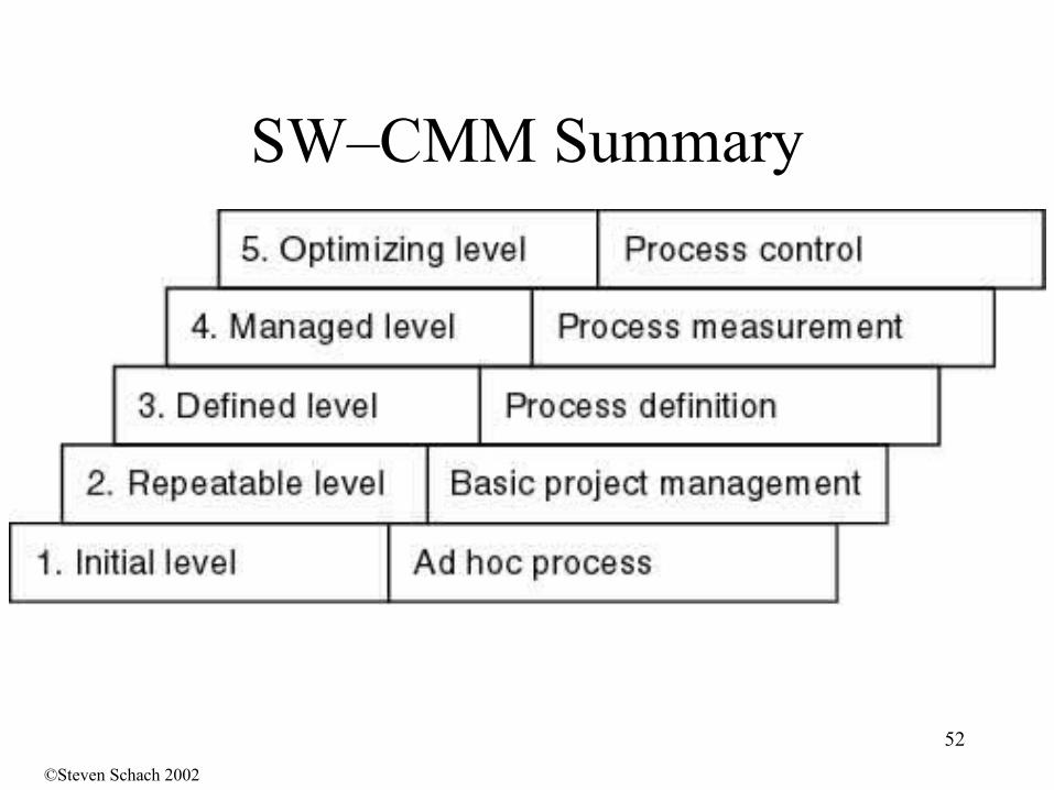
SW–CMM Summary
©Steven Schach 2002
53
• Any type of measurement which relates to a software system, process or related documentation– Lines of code in a program, number of person-days
required to develop a component
• Allow the software and the software process to be quantified
• Should be captured automatically and monitored if possible
Software metrics
©Ian Sommerville 1995 [modified]
54
• A quality metric should be a predictor of product quality
• Most quality metrics are design quality metrics and are concerned with measuring the coupling or the complexity of a design
• The relationship between these metrics and quality has to be judged by a human (no automatic connection to quality possible)
• Outliers may point to problems• There are no “magic thresholds,” rather the trend
of metrics over time needs to be monitored
Product quality metrics
©Ian Sommerville 1995 [modified]
55
Traditional Software Metics
• Coupling metrics (associated with a structure chart in Yourdon's Structured Design)– High number of calling functions or called functions suggests high
coupling• Cyclomatic complexity is a measure of control structure complexity
– Metric has two drawbacks• It is inaccurate for data-driven programs as it is only
concerned with control constructs.• It places the same weight on nested and non-nested loops.
Deeply nested structures, however, are usually harder to understand.
• Oviedo's metric modifies this to take data references into account– C = aE +bN
(with N external data entities, E edges to the data entities and constants a,b)
©Ian Sommerville 1995 [modified]
56
Metrics for Object-Oriented Software
• Traditional (still usable)– Cyclomatic complexity (CC)
• New OO metrics– Coupling
• Coupling between objects (CBO)• Depth of inheritance tree (DIT)• …
– Cohesion• Lack of cohesion of methods (LCOM)• …
– Complexity• Weighted methods per class (WMC)• …
57
• Time taken for process activities to be completed– E.g. Calendar time or effort to complete an activity
or process
• Resources required for processes or activities– E.g. Total effort in person-days
• Number of occurrences of a particular event– E.g. Number of defects discovered
• Process improvement requires process measurement!
Classes of process measurement (Process Metrics)
©Ian Sommerville 1995 [modified]
58
• Goals– What is the organisation trying to achieve? The
objective of process improvement is to satisfy these goals
• Questions– Questions about areas of uncertainty related to the
goals. You need process knowledge to derive these
• Metrics– Measurements to be collected to answer the
questions
Goal-Question-Metric Paradigm
©Ian Sommerville 1995 [modified]