Embed Size (px)
Citation preview

www.oilregeneration.globecore.com
GlobeCore High Vacuum Degasifier CMM (UVM) 4/7
GlobeCore Mobile High Vacuum Degasifier CMM (UVM) 4/7
Globecore GmbH
Edewechter Landstraße 173,
Oldenburg-Eversten,
Deutschland, 26131
Tel: +49 4484 202 35 91
Email: [email protected]
Skype: mg2globecore_de

CMM (UVM) 4/7 - will be supplied:
mounted on a roadworthy trailer with torsion suspension, appropriate reflectors
and tail lights and capable of being towed at speeds of up to 80km/h. It will be enclosed with water proof metal covers (protection class IP45) and have a
mechanism to secure plant in stationary position while in operation. Maximum noise level emitted by the unit will be below 80 db.
Production capacity of the unit will be between 1000 L/H and 4000 L/H and
provide:
• Removal of Water from 100 ppm down to 10 ppm and from 50 ppm
to 5 ppm in a single pass and down to 3 ppm after 3 passes (ASTM method
D-1533).
• Reduction of Gas content from fully saturated with air (10 to 12% by
volume) to less than 0.1 % (ASTM D-2945).
• Removal of Particulate Matter to 5 micron
• Improvement in dielectric strength up to 70 kV
COMPONENTS DESCRIPTION:
I. VACUUM SYSTEM
CMM (UVM) 4 will have the following vacuum facilities:
1. “GlobeCore” Rotary Vane Positive Displacement Pump
Pumping Speed 120 m3/h
Ultimate Pressure 0.5 mbar
2. “Globe Core” Vacuum Booster
Pumping Speed 334 m3/h
Ultimate Pressure 0.01 mbar
Vacuum Booster

II. VACUUM CHAMBER
This Oil Purification plant will have horizontal Vacuum Column with
Coalescers.
Vacuum Chamber Vessels and all internal parts are made of carbon steel and
feature Coalescers, Sight Glass, Oil Level Controller and Vacuum Gauge.
Vacuum Chamber’s rigid design makes it suitable for stationary and mobile
installation. Appropriate flexible connections are provided to the outlet
pump and inlet pump to minimize negative effect of vibration during plant
operation and transportation.
Vacuum Chamber
1–Oil Inlet
2–Vacuum Pump Connection
3–Coalescers
4–Oil Outlet
5–Level Sensor
6–Sight Glass
Coalescers - four built-in coalescers are provided for the maximum
exposure of oil to the effect of vacuum. Due to reduced pressure dissolved
water and gases are vaporised through secondary chamber and filter into
atmosphere.
Secondary Chamber (Oil Trap) - serves as safety feature to ensure that
no oil is pulled into the vacuum pump. It is equipped with oil level sensor
which will activate the alarm in case of oil presence.
Oil Level Controller - consists of three capacitive probes provided to
maintain required level of oil in the Vacuum Chamber.
Vacuum Gauge - is provided to monitor Vacuum level in the Vacuum
Chamber. Vacuum gauge will be absolute type with display in mbar.
Vacuum ports – vacuum connection is provided to pull vacuum on
transformer.
Sampling Ports – inlet and outlet oil ports are provided for incoming and
processed oil.
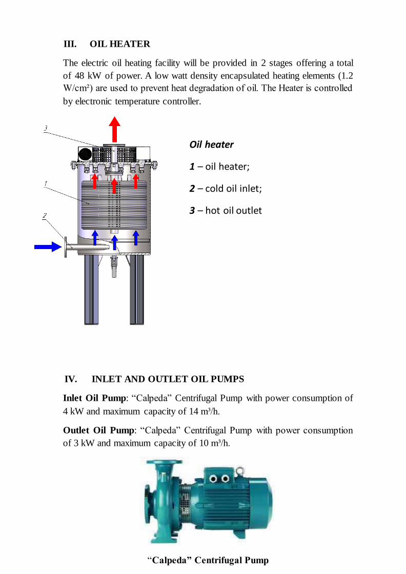
III. OIL HEATER
The electric oil heating facility will be provided in 2 stages offering a total
of 48 kW of power. A low watt density encapsulated heating elements (1.2
W/cm²) are used to prevent heat degradation of oil. The Heater is controlled
by electronic temperature controller.
IV. INLET AND OUTLET OIL PUMPS
Inlet Oil Pump: “Calpeda” Centrifugal Pump with power consumption of
4 kW and maximum capacity of 14 m³/h.
Outlet Oil Pump: “Calpeda” Centrifugal Pump with power consumption
of 3 kW and maximum capacity of 10 m³/h.
“Calpeda” Centrifugal Pump
Oil heater
1 – oil heater;
2 – cold oil inlet;
3 – hot oil outlet

V. FILTERS
A 90 micron Mesh Strainer is provided to remove large particles that could
cause damage to the Inlet Pump. 5 microns Coarse Filter is installed on
entry to the Vacuum Chamber. Oil receives its final treatment by passing
through the 1 micron Fine Filter designed to remove 99.9% of particles
larger than 1 micron.
VI. ALARMS AND INTERLOCKS
GlobeCore’s CMM plants feature the following safety devises which ensure
simple and reliable operation and will safely shut down the system in case of
any alarm situation:
High Level Alarm - will alert plant’s operator by activating sound and light
alarms and shut down the system safely should high level of oil persist.
Low Level Alarm – interlocked with the inlet pump low level alarm will
safely shut down the plant in case of insufficient oil level.
Flow Sensor - only activates the Heater when oil flow is detected.
Overloads – all motors are protected by overloads.
Alarms – sound and light alarm with silence button will alert plant’s
operator of any emergency situations.
Foam Sensor - prevents excessive foaming.
Coarse and fine Filters
1–Oil Inlet
2–Oil Outlet;
3–Drain Valve
4–Air Valve
5–Manual Air Discharge
6–Magnets
7–Clamp
8–Filter Cartridge

VII. INSTRUMENTATION AND CONTROLS
Control panel is a dust proof enclosure (protection class IP 54) featuring the
following elements:
Control cabinet general view
Control and measurement instruments.
Column’s residual pressure is controlled by electronic vacuum controller Autonics. Oil heater is controlled by following: - thermostat for oil heater disconnection if oil temperature is above 90 ºC;
- flow relay for oil heater disconnection when no oil flow is supplied through oil heater;
- temperature controller for oil temperature at heater outlet; - manometers indicate contamination of fine filters and pressure at unit outlet;
- level sensors control oil level in vacuum column. - foaming sensor controls foaming level in the vacuum column.

I. FLOW DIAGRAM
Typical Flow Diagram CMM (UVM) 4
СV – vacuum column; P1 – P2 – oil pumps; K1 – K5 , К7– K16 – ball
valves; K6 – vacuum valve, MN – oil heater; ВV– return valve; F1, F2 – fine
filters; М1, М2 , М3– manometer; ТP – temperature controller sensor; ТS –
thermostat; FS – flow switch; SV1- SV2 – electromagnetic valves; VG –
vacuum meter;
L1 – L4 – level sensors; VP1, VP2 – vacuum pumps; OS – foam sensor;
РF1 – mesh filter; R – trap; CL1, CL2 – camlock connections
OPERATIONAL PRINCIPLE
The unit can be operated in the following modes:
- oil heating and filtration
- filtration, heating and thermo-vacuum oil purification
- vacuummising of a transformer tank
Heating and filtration mode: oil goes through the unit via valve K1, mesh filter РF,
valve K10 pumped by oil pump P1 through the oil heater MN, cartridge filter F1, ball
valve K2, K5 to the unit output.

Filtration, heating and thermo-vacuum oil purification: transformer oil is fed
through valve K1, mesh filter РF, valve K10, oil pump P1 through oil heater MN,
cartridge filter F1. Heated to temperature (50…60ºС) and purified from mechanical
impurities oil is fed through ball valve K3, comes into vacuum column CV, passes
through coalescers. Vacuum in the chamber is created by vacuum pump VP. Vacuum
value in the chamber is maintained by means of the valve К11 and controlled by
vacuum gage VM. Air is supplied into chamber through moisture eliminator FV,
ascending air carries out gases and water vapour from the oil surface and in this way
the oil is dried. Wet air is subsequently removed into atmosphere via vacuum pump.
Oil from the column is fed to the transformer by oil pump P2 through valves K8, K9,
cartridge filter F2, return valve SV and ball valve K5 into the tank for clean oil. The K3
valve establishes necessary flow rate. The vacuum in the column is created by vacuum
pump VP1 and maintained at 0,8 bar during operation.
Vacuumizing of transformer: is carried out by pump VP through valve for
vacuumizing of the external equipment.
SPECIFICATIONS
Parameter Value
1. Capacity, m3/h, minimum
- in degassing, drying and filtration mode 4
- in heating and filtration mode 7
2. Capacity adjustment range, m3/h 0-4,0
3.* Processed oil parameters :
maximum gas content, %, max. 0,1
- maximum moisture content, g/t, max. 10
- ISO 4406 industrial purity class 9
- mechanical impurities content, g/t, max 8
- filtration rating, micron 5
-break through voltage, kV, minimum 70
4. Maximum oil outlet temperature in heating mode , ºС 90
5. filtration coefficient ≥50
6. Outlet pressure, MPa 0,35
7. Oil rise height support relative to outlet, m 35,0
8.Oil heater power, kW 50
9. Oil heater mean power, W/cm2, max
1,15
10. Maximum power consumption, kW, max. 60
11. Electric current parameters
- voltage, V 400
- AC frequency, Hz 50
12. Dimensions, mm, maximum
- length 3250
- height 1940
- width 1800
13. Weight, kg, max 1270

3D DIAGRAM and PICTURES
1 – Vacuum Chamber; 2 – Inlet Oil Pump ; 3 – Outlet Oil Pump; 4 – Pipes and Connections;
5 – Oil Heater; 6 – Fine Filter; 7 – Vacuum Pump; 8 – Vacuum Booster
GlobeCore High Vacuum Degasifier CMM (UVM) 4/7

GlobeCore Mobile High Vacuum Degasifier CMM (UVM) 4/7
Vacuum Column Vacuum Pumps
This plant comes complete with the set of spare parts sufficient for trouble free operation
during 1 years period.
WARRANTY: GlobeCore warrants the machinery supplied under this specification against defects in material and workmanship under normal use and
service for a period of 12 months from date of shipment.