Embed Size (px)
Citation preview
American Transactions on Engineering & Applied Sciences
http://TuEngr.com/ATEAS
Motion Analysis of Pitch Rotation Mechanism for Posture Control of Butterfly-style Flapping Robot Taro Fujikawa a*, Masahiro Shindo b, and Koki Kikuchi b
a Department of Robotics and Mechatronics, Tokyo Denki University, JAPAN b Department of Advanced Robotics, Chiba Institute of Technology, JAPAN A R T I C L E I N F O
A B S T RA C T
Article history: Received July 24, 2014 Accepted August 04, 2014 Available online August 08, 2014 Keywords: Flapping robot; Butterfly; Pitch rotation mechanism; Posture control; Pitch angle; Flapping angle.
We developed a small flapping robot on the basis of movements made by a butterfly with a low flapping frequency of approximately 10 Hz, a few degrees of freedom of the wings, and a large flapping angle. In this study, we clarify the pitch rotation mechanism that is used to control its posture during takeoff for different initial pitch and flapping angles by the experiments of both manufactured robots and simulation models. The results indicate that the pitch angle can be controlled by altering the initial pitch angle at takeoff and the flapping angles. Furthermore, it is suggested that the initial pitch angle generates a proportional increase in the pitch angle during takeoff, and that certain flapping angles are conducive to increasing the tendency for pitch angle transition. Thus, it is shown that the direction of the flight led by periodic changing in the pitch angle can be controlled by optimizing control parameters such as initial pitch and flapping angles.
2014 Am. Trans. Eng. Appl. Sci.
1. Introduction Flying robots with various methods of lift and propulsion, such as unmanned air vehicles,
airships, and multi-rotor helicopters, have been developed as observation systems because they
are unaffected by ground conditions and have high versatility (Green 2006, Fukao 2003, and
Holfman 2007). Although these robots exist in several sizes, smaller robots are effective for
2014 American Transactions on Engineering & Applied Sciences.
*Corresponding author (T.Fujikawa). Tel: +81-3-5284-5613 Fax: +81-3-5284-5698. E-mail addresses: [email protected]. 2014. American Transactions on Engineering & Applied Sciences. Volume 3 No. 4 ISSN 2229-1652 eISSN 2229-1660 Online Available at http://TUENGR.COM/ATEAS/V03/0251.pdf.
251
passing through narrow spaces. Here, flying creatures whose wings have high flight capabilities
such as ability to turn at right angles and to accelerate at more than 10 G from takeoff. The
flapping mechanism of small flying insects is particularly useful for maneuvering through narrow
spaces, such as gaps between debris. Although many insect-scale flapping robots have been
developed thus far, they have not achieved practical flight (Deng 2006, Fearing 2000, Sitti 2001,
and Wood 2008) because it is difficult to implement a heavy driving system such as a
conventional actuator consisting of a motor, gears, and a battery in such a small body. In
addition, the complexity of the link mechanism deteriorates the transmission efficiency because
the viscosity factors such as friction are more dominant than inertia at this scale. To overcome
such challenges, we developed a flapping robot modeled after a butterfly having a low flapping
frequency of approximately 10 Hz and a few degrees of freedom (DOF) of the wings. This robot
is equipped with a rubber motor as a lightweight actuator, which does not require converting
electrical energy into mechanical energy. Furthermore, it contains a simple slider-crank
mechanism with elastic links to enable a wide flapping angle. In our previous research (Udagawa
2007 and Fujikawa 2008, 2010), a manufactured flapping robot took off from an airspeed of 0
m/s and flew upward during the downstroke and then forward during the upstroke in a staircase
pattern to mimic the flight trajectory of a butterfly. However, posture control was not realized.
Here, one of the characteristics of the butterfly-style flight is a posture control mechanism that
raises the body pitch angle during the downstroke and lowers it during the upstroke, thereby
synchronizing with flapping motion. Although, a butterfly has a few DOF of the wings—control
of its wings is complicated—this insect flies skillfully.
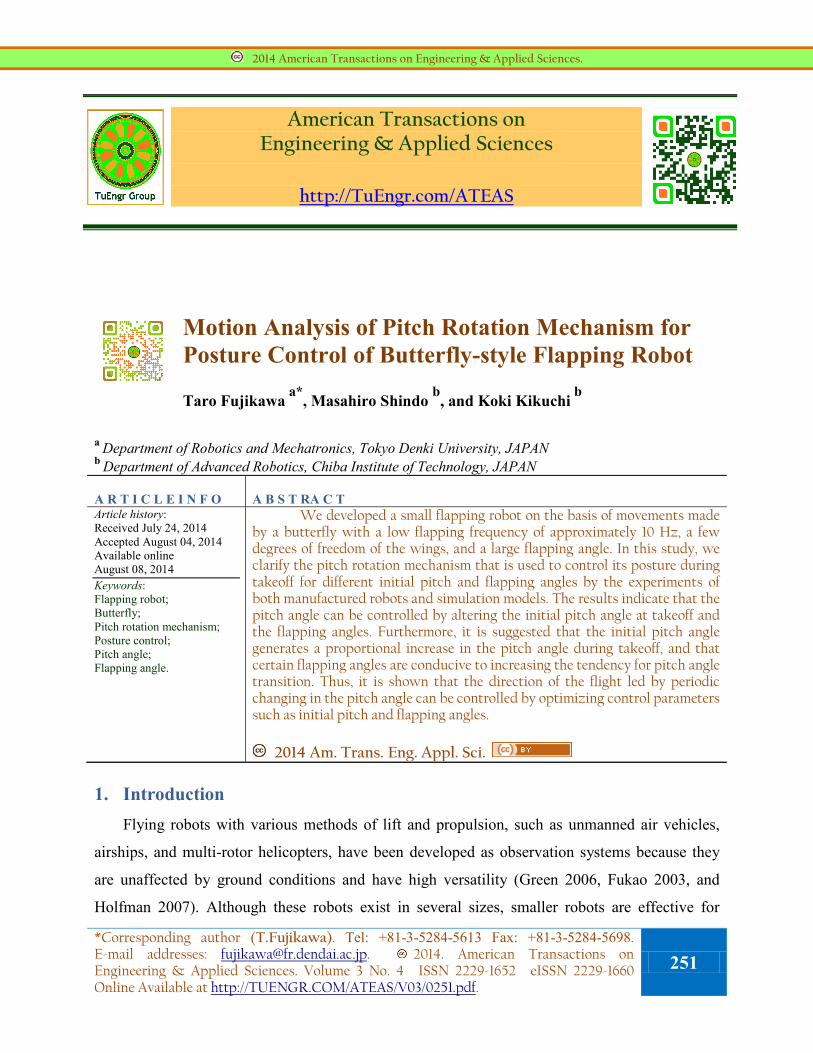
Figure 1: Definitions of parameters used in motion analysis.
252 Taro Fujikawa, Masahiro Shindo, and Koki Kikuchi
In this study, we analyze the periodical pitch rotation mechanism that affects the posture of a
butterfly during the takeoff by using a manufactured flapping robot and numerical simulation.
Furthermore, we clarify the posture control mechanism to realize autonomous flight of the
flapping robot.
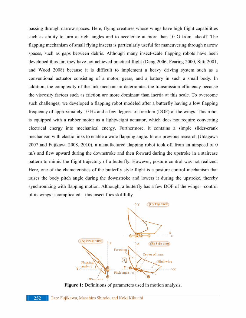
Figure 2: Stroboscopic photographs of a butterfly captured during takeoff
This paper is organized as follows: In section 2, we analyze the flight characteristics of a
butterfly. In section 3, we describe the butterfly-style flapping robot and numerical simulation
*Corresponding author (T.Fujikawa). Tel: +81-3-5284-5613 Fax: +81-3-5284-5698. E-mail addresses: [email protected]. 2014. American Transactions on Engineering & Applied Sciences. Volume 3 No. 4 ISSN 2229-1652 eISSN 2229-1660 Online Available at http://TUENGR.COM/ATEAS/V03/0251.pdf.
253
model. In section 4, we analyze and discuss the pitch rotation mechanism of both robots and the
simulation models. Finally, in section 5, we conclude the paper and outline future works.
2. Flight Characteristics of a Butterfly We analyzed the flight characteristics of a swallowtail butterfly (Papilio xuthus) during
takeoff by using a 3-D high-speed camera system with a resolution of 640 × 480 pixels and 200
fps (Fujikawa, 2010). Figure 1 shows the definitions of parameters used in the motion analysis,
and Figure 2 displays stroboscopic images of a butterfly captured during takeoff. The red line in
Figure 2 denotes the trajectory of the center of the thorax.
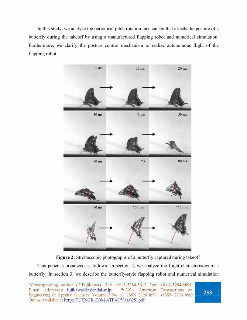
Figure 3 shows a typical example of the relationship between flapping and pitch angles. As
shown in the figure, the downstroke of the flapping begins at approximately 80 deg and the
upstroke begins at approximately −60 deg; that is, a butterfly flaps its wings in asymmetric
up-and-down motion. In addition, the pitch angle begins at approximately 20 deg and
periodically changes with a phase difference of approximately 90 deg between the flapping and
pitch angles. These results show that the asymmetric flapping angle and takeoff upon ascension
affect the pitch rotation. It is thought that a butterfly controls its posture through effective
management of these mechanisms.
Figure 3: Relationship between flapping and pitch angles during takeoff.
3. Butterfly-style flapping robot and numerical simulation model We manufactured a butterfly-style flapping robot and developed a numerical simulation
model. The robot as shown in Figure 4, which was constructed in bamboo to be lightweight, is
equipped with a rubber motor as an actuator for a high power–mass ratio. The wing membranes
are thin films made of polyethylene. The slider-crank mechanism mounted on its rear translates
the rotation of the actuator into the flapping motion of the wings. By bending the elastic links, a
254 Taro Fujikawa, Masahiro Shindo, and Koki Kikuchi
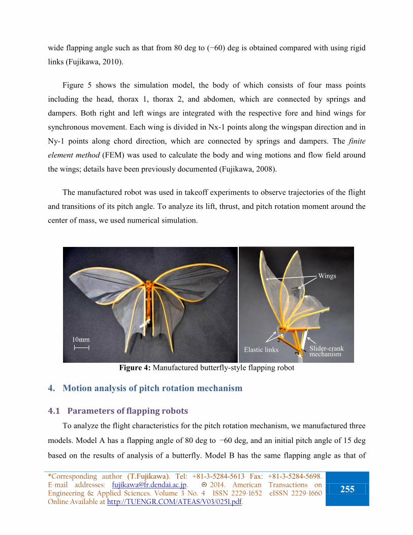
wide flapping angle such as that from 80 deg to (−60) deg is obtained compared with using rigid
links (Fujikawa, 2010).
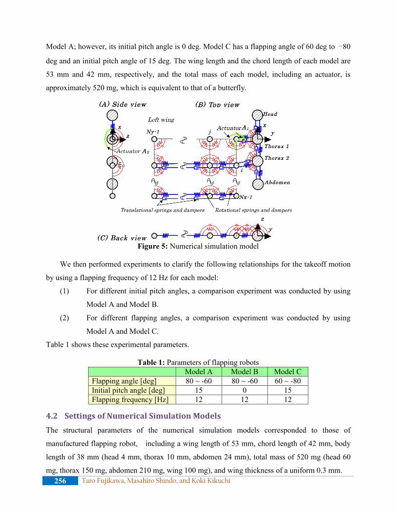
Figure 5 shows the simulation model, the body of which consists of four mass points
including the head, thorax 1, thorax 2, and abdomen, which are connected by springs and
dampers. Both right and left wings are integrated with the respective fore and hind wings for
synchronous movement. Each wing is divided in Nx-1 points along the wingspan direction and in
Ny-1 points along chord direction, which are connected by springs and dampers. The finite
element method (FEM) was used to calculate the body and wing motions and flow field around
the wings; details have been previously documented (Fujikawa, 2008).
The manufactured robot was used in takeoff experiments to observe trajectories of the flight
and transitions of its pitch angle. To analyze its lift, thrust, and pitch rotation moment around the
center of mass, we used numerical simulation.
Elastic links
Wings
Slider-crank mechanism
Figure 4: Manufactured butterfly-style flapping robot
4. Motion analysis of pitch rotation mechanism
4.1 Parameters of flapping robots To analyze the flight characteristics for the pitch rotation mechanism, we manufactured three
models. Model A has a flapping angle of 80 deg to −60 deg, and an initial pitch angle of 15 deg
based on the results of analysis of a butterfly. Model B has the same flapping angle as that of
*Corresponding author (T.Fujikawa). Tel: +81-3-5284-5613 Fax: +81-3-5284-5698. E-mail addresses: [email protected]. 2014. American Transactions on Engineering & Applied Sciences. Volume 3 No. 4 ISSN 2229-1652 eISSN 2229-1660 Online Available at http://TUENGR.COM/ATEAS/V03/0251.pdf.
255
Model A; however, its initial pitch angle is 0 deg. Model C has a flapping angle of 60 deg to −80
deg and an initial pitch angle of 15 deg. The wing length and the chord length of each model are
53 mm and 42 mm, respectively, and the total mass of each model, including an actuator, is
approximately 520 mg, which is equivalent to that of a butterfly.
Figure 5: Numerical simulation model
We then performed experiments to clarify the following relationships for the takeoff motion
by using a flapping frequency of 12 Hz for each model:
(1) For different initial pitch angles, a comparison experiment was conducted by using
Model A and Model B.
(2) For different flapping angles, a comparison experiment was conducted by using
Model A and Model C.
Table 1 shows these experimental parameters.
Table 1: Parameters of flapping robots Model A Model B Model C Flapping angle [deg] 80 ~ -60 80 ~ -60 60 ~ -80 Initial pitch angle [deg] 15 0 15 Flapping frequency [Hz] 12 12 12
4.2 Settings of Numerical Simulation Models The structural parameters of the numerical simulation models corresponded to those of
manufactured flapping robot, including a wing length of 53 mm, chord length of 42 mm, body
length of 38 mm (head 4 mm, thorax 10 mm, abdomen 24 mm), total mass of 520 mg (head 60
mg, thorax 150 mg, abdomen 210 mg, wing 100 mg), and wing thickness of a uniform 0.3 mm. 256 Taro Fujikawa, Masahiro Shindo, and Koki Kikuchi
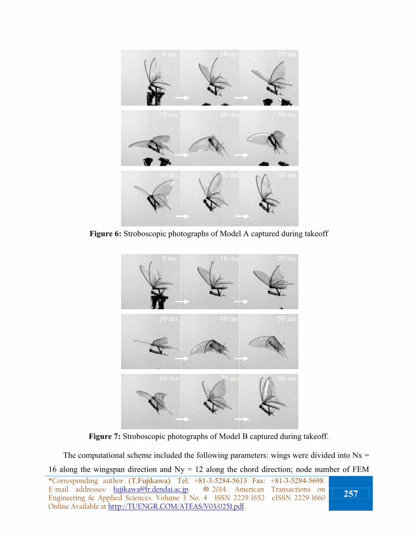
Figure 6: Stroboscopic photographs of Model A captured during takeoff
Figure 7: Stroboscopic photographs of Model B captured during takeoff.
The computational scheme included the following parameters: wings were divided into Nx =
16 along the wingspan direction and Ny = 12 along the chord direction; node number of FEM *Corresponding author (T.Fujikawa). Tel: +81-3-5284-5613 Fax: +81-3-5284-5698. E-mail addresses: [email protected]. 2014. American Transactions on Engineering & Applied Sciences. Volume 3 No. 4 ISSN 2229-1652 eISSN 2229-1660 Online Available at http://TUENGR.COM/ATEAS/V03/0251.pdf.
257
was approximately 700,000. The computational space was set to be approximately 1,300 ×
1,000 × 1,000 mm.
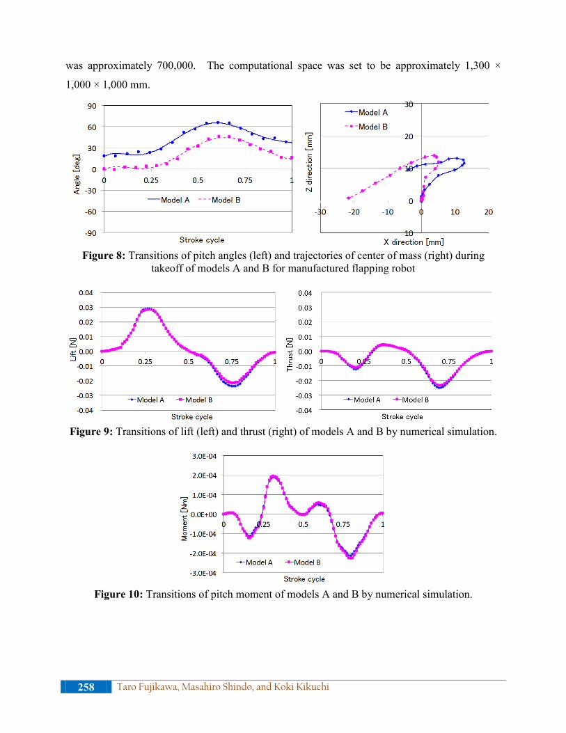
Figure 8: Transitions of pitch angles (left) and trajectories of center of mass (right) during
takeoff of models A and B for manufactured flapping robot
Figure 9: Transitions of lift (left) and thrust (right) of models A and B by numerical simulation.
Figure 10: Transitions of pitch moment of models A and B by numerical simulation.
258 Taro Fujikawa, Masahiro Shindo, and Koki Kikuchi
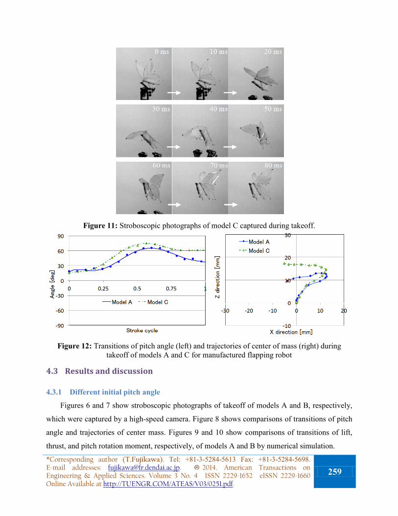
Figure 11: Stroboscopic photographs of model C captured during takeoff.
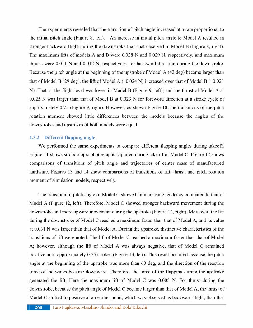
Figure 12: Transitions of pitch angle (left) and trajectories of center of mass (right) during
takeoff of models A and C for manufactured flapping robot
4.3 Results and discussion
4.3.1 Different initial pitch angle
Figures 6 and 7 show stroboscopic photographs of takeoff of models A and B, respectively,
which were captured by a high-speed camera. Figure 8 shows comparisons of transitions of pitch
angle and trajectories of center mass. Figures 9 and 10 show comparisons of transitions of lift,
thrust, and pitch rotation moment, respectively, of models A and B by numerical simulation.
*Corresponding author (T.Fujikawa). Tel: +81-3-5284-5613 Fax: +81-3-5284-5698. E-mail addresses: [email protected]. 2014. American Transactions on Engineering & Applied Sciences. Volume 3 No. 4 ISSN 2229-1652 eISSN 2229-1660 Online Available at http://TUENGR.COM/ATEAS/V03/0251.pdf.
259
The experiments revealed that the transition of pitch angle increased at a rate proportional to
the initial pitch angle (Figure 8, left). An increase in initial pitch angle to Model A resulted in
stronger backward flight during the downstroke than that observed in Model B (Figure 8, right).
The maximum lifts of models A and B were 0.028 N and 0.029 N, respectively, and maximum
thrusts were 0.011 N and 0.012 N, respectively, for backward direction during the downstroke.
Because the pitch angle at the beginning of the upstroke of Model A (42 deg) became larger than
that of Model B (29 deg), the lift of Model A (−0.024 N) increased over that of Model B (−0.021
N). That is, the flight level was lower in Model B (Figure 9, left), and the thrust of Model A at
0.025 N was larger than that of Model B at 0.023 N for foreword direction at a stroke cycle of
approximately 0.75 (Figure 9, right). However, as shown Figure 10, the transitions of the pitch
rotation moment showed little differences between the models because the angles of the
downstrokes and upstrokes of both models were equal.
4.3.2 Different flapping angle
We performed the same experiments to compare different flapping angles during takeoff.
Figure 11 shows stroboscopic photographs captured during takeoff of Model C. Figure 12 shows
comparisons of transitions of pitch angle and trajectories of center mass of manufactured
hardware. Figures 13 and 14 show comparisons of transitions of lift, thrust, and pitch rotation
moment of simulation models, respectively.
The transition of pitch angle of Model C showed an increasing tendency compared to that of
Model A (Figure 12, left). Therefore, Model C showed stronger backward movement during the
downstroke and more upward movement during the upstroke (Figure 12, right). Moreover, the lift
during the downstroke of Model C reached a maximum faster than that of Model A, and its value
at 0.031 N was larger than that of Model A. During the upstroke, distinctive characteristics of the
transitions of lift were noted. The lift of Model C reached a maximum faster than that of Model
A; however, although the lift of Model A was always negative, that of Model C remained
positive until approximately 0.75 strokes (Figure 13, left). This result occurred because the pitch
angle at the beginning of the upstroke was more than 60 deg, and the direction of the reaction
force of the wings became downward. Therefore, the force of the flapping during the upstroke
generated the lift. Here the maximum lift of Model C was 0.005 N. For thrust during the
downstroke, because the pitch angle of Model C became larger than that of Model A, the thrust of
Model C shifted to positive at an earlier point, which was observed as backward flight, than that
260 Taro Fujikawa, Masahiro Shindo, and Koki Kikuchi
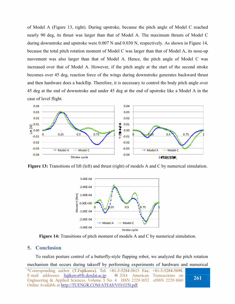
of Model A (Figure 13, right). During upstroke, because the pitch angle of Model C reached
nearly 90 deg, its thrust was larger than that of Model A. The maximum thrusts of Model C
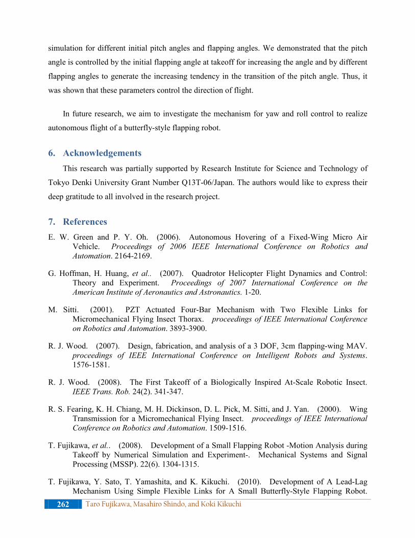
during downstroke and upstroke were 0.007 N and 0.030 N, respectively. As shown in Figure 14,
because the total pitch rotation moment of Model C was larger than that of Model A, its nose-up
movement was also larger than that of Model A. Hence, the pitch angle of Model C was
increased over that of Model A. However, if the pitch angle at the start of the second stroke
becomes over 45 deg, reaction force of the wings during downstroke generates backward thrust
and then hardware does a backflip. Therefore, it is necessary to control the body pitch angle over
45 deg at the end of downstroke and under 45 deg at the end of upstroke like a Model A in the
case of level flight.
Figure 13: Transitions of lift (left) and thrust (right) of models A and C by numerical simulation.
Figure 14: Transitions of pitch moment of models A and C by numerical simulation.
5. Conclusion To realize posture control of a butterfly-style flapping robot, we analyzed the pitch rotation
mechanism that occurs during takeoff by performing experiments of hardware and numerical *Corresponding author (T.Fujikawa). Tel: +81-3-5284-5613 Fax: +81-3-5284-5698. E-mail addresses: [email protected]. 2014. American Transactions on Engineering & Applied Sciences. Volume 3 No. 4 ISSN 2229-1652 eISSN 2229-1660 Online Available at http://TUENGR.COM/ATEAS/V03/0251.pdf.
261
simulation for different initial pitch angles and flapping angles. We demonstrated that the pitch
angle is controlled by the initial flapping angle at takeoff for increasing the angle and by different
flapping angles to generate the increasing tendency in the transition of the pitch angle. Thus, it
was shown that these parameters control the direction of flight.
In future research, we aim to investigate the mechanism for yaw and roll control to realize
autonomous flight of a butterfly-style flapping robot.
6. Acknowledgements This research was partially supported by Research Institute for Science and Technology of
Tokyo Denki University Grant Number Q13T-06/Japan. The authors would like to express their
deep gratitude to all involved in the research project.
7. References E. W. Green and P. Y. Oh. (2006). Autonomous Hovering of a Fixed-Wing Micro Air
Vehicle. Proceedings of 2006 IEEE International Conference on Robotics and Automation. 2164-2169.
G. Hoffman, H. Huang, et al.. (2007). Quadrotor Helicopter Flight Dynamics and Control: Theory and Experiment. Proceedings of 2007 International Conference on the American Institute of Aeronautics and Astronautics. 1-20.
M. Sitti. (2001). PZT Actuated Four-Bar Mechanism with Two Flexible Links for Micromechanical Flying Insect Thorax. proceedings of IEEE International Conference on Robotics and Automation. 3893-3900.
R. J. Wood. (2007). Design, fabrication, and analysis of a 3 DOF, 3cm flapping-wing MAV. proceedings of IEEE International Conference on Intelligent Robots and Systems. 1576-1581.
R. J. Wood. (2008). The First Takeoff of a Biologically Inspired At-Scale Robotic Insect. IEEE Trans. Rob. 24(2). 341-347.
R. S. Fearing, K. H. Chiang, M. H. Dickinson, D. L. Pick, M. Sitti, and J. Yan. (2000). Wing Transmission for a Micromechanical Flying Insect. proceedings of IEEE International Conference on Robotics and Automation. 1509-1516.
T. Fujikawa, et al.. (2008). Development of a Small Flapping Robot -Motion Analysis during Takeoff by Numerical Simulation and Experiment-. Mechanical Systems and Signal Processing (MSSP). 22(6). 1304-1315.
T. Fujikawa, Y. Sato, T. Yamashita, and K. Kikuchi. (2010). Development of A Lead-Lag Mechanism Using Simple Flexible Links for A Small Butterfly-Style Flapping Robot.
262 Taro Fujikawa, Masahiro Shindo, and Koki Kikuchi
ISIAC2010.
T. Fukao, K. Fujitani, T. Kanade. (2003). An autonomous blimp for a surveillance system. Proceedings of 2003 IEEE/RSJ International Conference on Intelligent Robots and Systems. 1829-1825.
T. Udagawa, T. Fujikawa, X. GAO, and K. Kikuchi. (2005). Development of a Small-Sized Flapping Robot. JSDE The 1st International Conference on Design Engineering and Science. 283-288.
X. Deng, L. Schenato, W. Chung Wu, and S. S. Sastry. (2006). Flapping Flight for Biomimetic Robotic Insects: Part I – System Modeling. IEEE Trans. Rob.. 22(4). 776-788.
Dr. Taro Fujikawa is an Assistant Professor of Department of Robotics and Mechatronics at Tokyo Denki University, Japan. He received his Ph.D. in Engineering from Chiba Institute of Technology, Japan, in 2011. From 2011 to 2012, he was a Postdoctoral Researcher at Research Institute of Chiba Institute of Technology. He was a recipient of the Miura Award, the Japan Society of Mechanical Engineers in 2007, and the Best Paper Award of the 1st International Conference of Design Engineering and Science (ICDES2005). His research interests include biomimetic robots, mobility vehicles, and mechanical engineering design.
Masahiro Shindo is a graduate student of Department of Advanced Robotics, Chiba Institute of Technology, Japan. He received his degree in Engineering from Chiba Institute of Technology in 2013. He also received the Hatakeyama Award, the Japan Society of Mechanical Engineers in 2013. He investigates the flight mechanism of a butterfly using a three-dimensional computational fluid analysis and an insect-scale flapping robot.
Dr.Koki Kikuchi is a professor of Department of Advanced Robotics, Chiba Institute of Technology, Japan. He received his Ph.D. in Engineering from Tokyo University of Science in 1999. He also received the best paper award of the International Conference of Design Engineering and Science (ICDES2005) from Japan Society of Design Engineering, JSDE, and the best paper award of journal of JSDE. He investigates mechanisms creating insect abilities and develops small robots such as a butterfly-style flapping robot, vertical wall climbing robot, on-water running robot, etc. based on insect scale physics.
Peer Review: The original of this article has been submitted to The 3rd International Conference on Design Engineering and Science (ICDES 2014), held at Pilsen, Czech Republic. The Paper Award Committee of ICDES 2014 has reviewed and selected this paper for journal publication.
*Corresponding author (T.Fujikawa). Tel: +81-3-5284-5613 Fax: +81-3-5284-5698. E-mail addresses: [email protected]. 2014. American Transactions on Engineering & Applied Sciences. Volume 3 No. 4 ISSN 2229-1652 eISSN 2229-1660 Online Available at http://TUENGR.COM/ATEAS/V03/0251.pdf.
263

![Dynamics and flight control of a flapping- wing robotic ... · aerodynamics of flapping-wing flight [8,13–15]. Despite having achieved stable flight, the flapping-wing robot in](https://img.pdfslide.net/doc/110x75/5e232a06436fd7265e4f446b/dynamics-and-flight-control-of-a-flapping-wing-robotic-aerodynamics-of-flapping-wing.jpg)